VLF LF 10KHz - 500KHz Up Converter. Brochure. HEROS technology Limited All rights reserved
|
|
|
- Cassandra Randall
- 6 years ago
- Views:
Transcription
1 Brochure
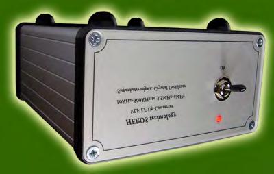
2 Since many countries are allocating the old 500KHz (600m) maritime radio distress band for experimental use by Radio Amateurs, a growing number of them as well as listeners have become interested on VLF and LF bands. The fact that few radios are available on the market covering frequencies from below 10KHz to 500KHz, convinced us to provide radio amateurs with the high-performance receiving VLF-LF Converter that we introduce here. The VLF-LF Converter extents the range of any shortwave receiver to below 10 KHz to 500 KHz. It connects between the antenna and the HF radio. When turned ON the <10KHz to 500 KHz band translates to HF receive tuning, 3.500MHz MHz, Model-350 or 4.000MHz MHz, Model 400, allowing enjoy the world of VLF and LF bands, including the 500KHZ band. For example, if a conversion frequency of 4.000MHz MHz, Model 400, is used, and the receiver tuned on MHz, you are receiving on KHz, just ignoring the digit 4 on the dial. The VLF LF Converter permits the reception of navigational beacons (NDB), standard frequency broadcasts, NAVTEX, weather broadcasts, LORAN, the 137KHz and 500KHz Amateur bands, European LW broadcast stations, monitoring the sounds of nature created by planet Earth (Natural Radio) such as sferics, hiss, tweeks, whistlers, Dawn Chorus, other not well know VLF radio atmospherics sounds, and many more. Technical Specifications: - Type: Superheterodyne converter. Double balanced mixer; Quartz crystal oscillator. - Frequency range: <10KHz to 500KHz. including 600m band. - IF output: 3.5MHz-4MHz, model 350; 4MHz-4.5MHz; model Input/Output impedance: 50 Ω - Gain: 5 db - IF rejection: 110dB typical. - MW band rejection: 80dB - Crystal oscillator: Low phase noise; quartz crystal ±10ppm; 3.5MHz or 4MHz, fundamental. - Power: 12volts/40mA - Enclosure: Aluminium - Size: 125mmx105mx55mm ( 4.921x4.133x2.165in)
3 Earth RF Output Antenna RX antenna input DC 12V/40mA + VLF LF Up Converter Inter connection diagram
 Earth RX antenna")

4 Earth Antenna RF Output PTT or Keying line control (13mA loop) Earth RX antenna input DC 12V/40mA + VLF LF Up Converter interconnection with Dual By-Pass relay. Diagram
5 B A 500KHz 7 poles Elliptic LPF -110dB IF trap Double Balanced Mixer Mini-Circuits SRA-8 BPF Diplexer Post-Mixer LNA amplifier IF RF J1 D 1 1 Antenna Input (50Ω) 10KHz 500KHz C LNA LO +7dBm Input Filters Conversor Output (50Ω) Output 3.5MHz - 4MHz or 4MHz - 4,5MHz Gas Discharge Tube 2 2 Power Reg Buffer Amplifier 4MHz 7 poles Elliptic LPF 3 3 Crystal Oscillator 3,5MHz or 4MHz Local Oscillator 4 4 Drawing Approvals A B C VLF LF Converter Diagram Size DWG No Sheet 1/1 REV A4 Issued Scale FCSM No Checked Drawn JJ de Oñate Date XV II MMX HEROS technology Limited All rights reserved D


6 Input Filters Referring to the above functional blocks diagram, the 50 Ω antenna is connected to J1,BNC type connector; a Gas Discharge Tube protects the converter from transients that may come from the antenna. Next the input filters section is a combination of a 110dB IF trap and a 7th order, 0.3dB insertion loss, Elliptic Low Pass Filter with a cut-off frequency of 500 khz. This section provides good performance right up to the start of the AM broadcast band with a sharp roll-off, giving a good rejection to MW broadcast signals avoiding introducing overload or intermodulation products in the receiver. Local Oscillator Low phase noise, crystal controlled oscillator provides +7dBm signal level to the mixer. A good quality quartz crystal of 3.5MHz or 4MHz, according to the model of converter, is used. A trimmer capacitor is accessible by the user if fine adjust of frequency is required in times. A linear fixed voltage IC regulates the voltage applied to the oscillator to enhance stability and avoid drift. The oscillator is followed by a buffer stage to improve its stability. Next, an amplifier accommodates the signal to the required level. It connects to a 4 MHz, 7th order, Elliptic Low Pass Filter which cleans up any harmonics and assures that a pure signal applies to the mixer to minimize spurious responses. Mixer The mixer stage is designed around a Mini-Circuits SRA-8+ double balanced mixer. It is rated to operate from 500Hz, giving and excellent frequency coverage. Designed for +7 dbm of LO power, it have a conversion loss of less than 5 db at VLF LF bands, which is compensate by the post-mixer amplifier. A double balanced mixer has the advantage of high port-to-port isolation, which keeps the strong LO signal from degrading the dynamic range of the IF receiver. Every effort has been made to terminate the ports of the mixer in a proper 50 Ω impedance to maximize its performance. The mixer IF port is most critical in terms of proper termination, for so, a diplexer circuit provides a 50 Ω resistive load to the mixer while passing the desired signal to the IF amplifier, with minimum loss. Next, a Band Pass filter at IF frequency connects to a Low Noise Amplifier to compensate losses, delivering around 5dB of gain to the output, necessary to overcome losses from external cable tails, relays and connectors.


7 Design A carefully PCB and shielding design keep feed through signals of the HF receiving frequency down to a very low l evel; therefore, weak LF signals will not be interfered by strong HF signals on the same frequency. The HF receiver used should have strong rejection of HF signals through paths other than the antenna connector. Most HF transceivers and receivers have good performance in this respect, but some SWL receivers do not and may be used with the addition of filters and shielding. Operating The VLF LF Converter is suitable for use with active antennas, loops and preamplifiers that provide a 50 Ω output. Beverage antennas may need a matching network device or Magnetic loop for best performance. Using an active antenna, be sure the power coupler does not introduces a DC voltage across the antenna input that may destroy the converter mixer. IMPORTANT: When using a HF transceiver as IF receiver, take precautions to prevent transmitting any signal into the converter. Oscillator calibration The VLF-LF Up-converter comes calibrated from factory after a burn test of 24 hours. If for any reason you need to recalibrate the local oscillator proceed as follows: Remove the four front panel screws and slide gently the lid. You may untie the two upper screws on rear panel.


8 Remove the lid from the local oscillator section. Switch ON the converter. Allow at least 30 minutes of warming time before adjusting at room temperature. Measuremet point Adjust trimmer
9 NOTES: Heros technology Limited disclaims all liability arising from this information and its use. It is your responsibility to ensure that your application meets with your specifications. Information contained in this publication regarding device applications and the like is provided only for your convenience and may be superseded by updates. Heros technology Limited makes no representations or warranties of any kind whether express or implied, written or oral, statutory or otherwise, related to the information, including but not limited to its condition, quality, performance, merchantability or fitness for purpose.
VLF-LF Up Converter 5KHz - 500KHz. User manual. Rev HEROS technology Limited All rights reserved
 VLF-LF Up Converter 5KHz - 500KHz User manual. Rev 2016-02 Since many countries are allocating the 472 khz to 479kHZ band for experimental use by Radio Amateurs, a growing number of them as well as listeners
VLF-LF-MF Up Converter
 VLF-LF-MF Up Converter 5kHz-500kHz 3.5MHz-4MHz model 350 4MHz-4.5MHz model 400 User manual. Rev 2018-01 Since many countries are allocating the 472 khz to 479kHZ band for experimental use by Radio Amateurs,
HF Receivers, Part 2
 HF Receivers, Part 2 Superhet building blocks: AM, SSB/CW, FM receivers Adam Farson VA7OJ View an excellent tutorial on receivers NSARC HF Operators HF Receivers 2 1 The RF Amplifier (Preamp)! Typical
The 144MHz Anglian 3 transverter
 The 144MHz Anglian 3 transverter A high performance 144/28MHz transverter G4DDK document issue 1 12/9/16 Introduction Anglian 3 is an update to the 144MHz Anglian 2 transverter. The Anglian 2 is no longer
RADIO RECEIVERS ECE 3103 WIRELESS COMMUNICATION SYSTEMS
 RADIO RECEIVERS ECE 3103 WIRELESS COMMUNICATION SYSTEMS FUNCTIONS OF A RADIO RECEIVER The main functions of a radio receiver are: 1. To intercept the RF signal by using the receiver antenna 2. Select the
Construction Manual 4m-Linear-Transverter XV4-15
 Construction Manual 4m-Linear-Transverter XV4-15 Holger Eckardt DF2FQ Kirchstockacherstr. 33 D-85662 Hohenbrunn 3207 Technical data exciter frequency: 21.0... 21.5 MHz RF frequency: 70.0.. 70.5 MHz supply
Construction Manual 6m-Linear-Transverter XV6/10
 Construction Manual 6m-Linear-Transverter XV6/10 Holger Eckardt DF2FQ Kirchstockacherstr. 33 D-85662 Hohenbrunn 2606 Technical data exciter frequency: 28... 30 MHz RF frequency: 50... 52 MHz supply voltage:
Radio Receivers. Al Penney VO1NO
 Radio Receivers Role of the Receiver The Antenna must capture the radio wave. The desired frequency must be selected from all the EM waves captured by the antenna. The selected signal is usually very weak
Introduction to Receivers
 Introduction to Receivers Purpose: translate RF signals to baseband Shift frequency Amplify Filter Demodulate Why is this a challenge? Interference Large dynamic range required Many receivers must be capable
Stereo Clipper 15KHz LPF. Stereo audio clipper with active 15KHz filters
 Stereo Clipper 15KHz LPF Stereo audio clipper with active 15KHz filters Dimension (L x W x H): 62mm x 50mm x 15mm FMB stereo audio clipper with active 15KHz filters, is an audio board with professional
Module 8 Theory. dbs AM Detector Ring Modulator Receiver Chain. Functional Blocks Parameters. IRTS Region 4
 Module 8 Theory dbs AM Detector Ring Modulator Receiver Chain Functional Blocks Parameters Decibel (db) The term db or decibel is a relative unit of measurement used frequently in electronic communications
Interference & Suppression Page 59
 INTERFERENCE Interference & Suppression Page 59 Front-End Overload, Cross-Modulation What is meant by receiver overload? Interference caused by strong signals from a nearby transmitter What is one way
BGU8309 GNSS LNA evaluation board
 BGU8309 GNSS LNA evaluation board Rev. 2 12 August 2016 Application note Document information Info Content Keywords BGU8309, GNSS, LNA Abstract This document explains the BGU8309 GNSS LNA evaluation board
Data Sheet SC5317 & SC5318A. 6 GHz to 26.5 GHz RF Downconverter SignalCore, Inc. All Rights Reserved
 Data Sheet SC5317 & SC5318A 6 GHz to 26.5 GHz RF Downconverter www.signalcore.com 2018 SignalCore, Inc. All Rights Reserved Definition of Terms 1 Table of Contents 1. Definition of Terms... 2 2. Description...
TS-930: Installing the Inrad Roofing Filter Mod
 TS-930: Installing the Inrad Roofing Filter Mod The TS-930 roofing filter mod consists of a 6 pole, 4 to 5 khz wide filter followed by a high dynamic range, feedback amplifier. The amplifier provides enough
Frequency range: BAND RANGE MHz MHz
 INSTRUCTION SHEET NO. 20 POWER-MITE PM3 and PM3A DESCRIPTION The Power-Mite 3 and 3A are self-contained CW transceivers covering 40 and 20 meters. The receiver is compromised of a variable oscillator operating
Radio Receivers. Al Penney VO1NO
 Radio Receivers Al Penney VO1NO Role of the Receiver The Antenna must capture the radio wave. The desired frequency must be selected from all the EM waves captured by the antenna. The selected signal is
Modifying the RX320 Receiver for LF/VLF Operation
 Modifying the RX320 Receiver for LF/VLF Operation BACKGROUND The RX320 has gotten a lot of enthusiasm from users and reviewers for its cost vs. performance on the HF bands. It is rated down to 100 khz
SC5307A/SC5308A 100 khz to 6 GHz RF Downconverter. Datasheet SignalCore, Inc.
 SC5307A/SC5308A 100 khz to 6 GHz RF Downconverter Datasheet 2017 SignalCore, Inc. support@signalcore.com P RODUCT S PECIFICATIONS Definition of Terms The following terms are used throughout this datasheet
VLF & ULF Signals, Receivers & Antennas - Listening to the sounds of the atmosphere
 VLF & ULF Signals, Receivers & Antennas - Listening to the sounds of the atmosphere A presentation to Manly-Warringah Radio Society from Geoff Osborne VK2TGO VLF & ULF Signals, Receivers and Antennas 1.
Dual Band Filter Assembly Manual
 Dual Band Filter Assembly Manual 12 January 2018 Rev D Version Theory of Operation: The purpose of a Bandpass Filter is to filter out or reject all unwanted signals. The original KN-Q7A Receive Filter
User Manual. User Manual. Tri-Band Repeater February. -- Tri-Band Repeater (Model: RP33EDW) (900/1800/2100)
 (900/1800/2100)") Tri-Band Repeater (900/1800/2100) User Manual 2015 February Information in this manual is subject to change without notice http:www.redutelco.com 2009 Redutelco All rights reserved 1 Table of Contents
Tri-Band Repeater (900/1800/2100) User Manual 2015 February Information in this manual is subject to change without notice http:www.redutelco.com 2009 Redutelco All rights reserved 1 Table of Contents
SA620 Low voltage LNA, mixer and VCO 1GHz
 INTEGRATED CIRCUITS Low voltage LNA, mixer and VCO 1GHz Supersedes data of 1993 Dec 15 2004 Dec 14 DESCRIPTION The is a combined RF amplifier, VCO with tracking bandpass filter and mixer designed for high-performance
Receiver Design. Prof. Tzong-Lin Wu EMC Laboratory Department of Electrical Engineering National Taiwan University 2011/2/21
 Receiver Design Prof. Tzong-Lin Wu EMC Laboratory Department of Electrical Engineering National Taiwan University 2011/2/21 MW & RF Design / Prof. T. -L. Wu 1 The receiver mush be very sensitive to -110dBm
Isolated Linearized 4-Wire RTD Input 5B35 FEATURES APPLICATIONS PRODUCT OVERVIEW FUNCTIONAL BLOCK DIAGRAM
 Isolated Linearized 4-Wire RTD Input 5B35 FEATURES Single-channel signal conditioning module that Amplifies, Protects, Filters, and Isolates Analog Input. Isolates and protects a wide variety of four-wire
SDI SPECTRADYNAMICS, INC. LOW NOISE FREQUENCY REFERENCE OPERATING MANUAL
 SPECTRADYNAMICS, INC. LOW NOISE FREQUENCY REFERENCE LNFR-100E OPERATING MANUAL SPECTRADYNAMICS, INC 1849 Cherry St. Unit 2. Louisville, CO 80027 Phone: (303) 665-1852 Fax: (303) 604-6088 www.spectradynamics.com
FREQUENCY AGILE FM MODULATOR INSTRUCTION BOOK IB
 FMT615C FREQUENCY AGILE FM MODULATOR INSTRUCTION BOOK IB1215-02 TABLE OF CONTENTS SECTION SUBJECT 1.0 Introduction 2.0 Installation & Operating Instructions 3.0 Specification 4.0 Functional Description
Analysis of RF transceivers used in automotive
 Scientific Bulletin of Politehnica University Timisoara TRANSACTIONS on ELECTRONICS and COMMUNICATIONS Volume 60(74), Issue, 0 Analysis of RF transceivers used in automotive Camelia Loredana Ţeicu Abstract
1:1 AND 1:2 REDUNDANT LOW-NOISE AMPLIFIER SYSTEMS
 FEATURES Low amplifier noise temperature Fully redundant power supplies Remote control via RS485 matic/manual control from both local and remote mode Remote status Off-line input/output access Amplifier
Today s communication
 From October 2009 High Frequency Electronics Copyright 2009 Summit Technical Media, LLC Selecting High-Linearity Mixers for Wireless Base Stations By Stephanie Overhoff Maxim Integrated Products, Inc.
HF Amateur SSB Receiver
 HF Amateur SSB Receiver PCB Set for radio club project http://rhelectronics.net PCB for DIY HF Amateur SSB Receiver 20M The receiver is a simple syperheterodyne type with quartz crystal filter. The circuit
Isolated High Level Voltage Output 7B22 FEATURES APPLICATIONS PRODUCT OVERVIEW FUNCTIONAL BLOCK DIAGRAM
 Isolated High Level Voltage Output 7B22 FEATURES Unity gain single-channel signal conditioning output module. Interfaces and filters a +10 V input signal and provides an isolated precision output of +10V.
Model AAA-1C. Addendum to AAA-1B documentation
 Model AAA-1C. Addendum to AAA-1B documentation 1. Specifications for Model AAA-1C (11) General Output impedance Power supply (1) Maximal output voltage (10) Physical size 50 Ohms, BNC connector on control
SA601 Low voltage LNA and mixer 1 GHz
 INTEGRATED CIRCUITS Low voltage LNA and mixer 1 GHz Supersedes data of 1994 Dec 15 2004 Dec 14 DESCRIPTION The is a combined RF amplifier and mixer designed for high-performance low-power communication
Updating KK7B, SHF,DEM or DEMI 900 and 1296 MHz. transverters
 Updating KK7B, SHF,DEM or DEMI 900 and 1296 MHz. transverters By Steve Kostro, N2CEI PREFACE: Yes, It may be hard to believe, but the original 900 and 1296 No-Tune transverter concepts have been around
Model 1791 VHF Radio User's Manual
 Model 79 VHF Radio User's Manual ALL WEATHER INC 65 NATIONAL DRIVE SACRAMENTO, CA 95834 WWW.ALWEATHERINC.COM 79 VHF RADIO USER'S MANUAL CONTENTS INTRODUCTION... Description... Transmitter Module... Power
Preliminary Information (There will be updates)
") This Manual is provided by CBTricks.com Someone who wanted to help you repair your equipment put together this information. Cobra150GTL DX If you would like to help us put more manuals online support us.
This Manual is provided by CBTricks.com Someone who wanted to help you repair your equipment put together this information. Cobra150GTL DX If you would like to help us put more manuals online support us.
KWM-2/2A Transceiver THE COLLINS KWM-2/2A TRANSCEIVER
 KWM-2/2A Transceiver Click the photo to see a larger photo Click "Back" button on browser to return Courtesy of Norm - WA3KEY THE COLLINS KWM-2/2A TRANSCEIVER Unmatched for versatility, dependability and
PLL Synchronizer User s Manual / Version 1.0.6
 PLL Synchronizer User s Manual / Version 1.0.6 AccTec B.V. Den Dolech 2 5612 AZ Eindhoven The Netherlands phone +31 (0) 40-2474321 / 4048 e-mail AccTecBV@tue.nl Contents 1 Introduction... 3 2 Technical
MAINTENANCE MANUAL RF BOARD 19D901835G1 ( MHz) 19D901835G2 ( MHz) FOR MVS
 19D901835G2 ( MHz) FOR MVS") D MAINTENANCE MANUAL F BOAD 19D901835G1 (136-153 MHz) 19D901835G2 (150-174 MHz) FO MVS TABLE OF CONTENTS DESCIPTION............................................... Front Cover CICUIT ANALYSIS..............................................
D MAINTENANCE MANUAL F BOAD 19D901835G1 (136-153 MHz) 19D901835G2 (150-174 MHz) FO MVS TABLE OF CONTENTS DESCIPTION............................................... Front Cover CICUIT ANALYSIS..............................................
INSTALLATION AND OPERATING MANUAL
 INSTALLATION AND OPERATING MANUAL FOR RBDA-PCS-1/25W-90-A INDOOR REPEATER TABLE OF CONTENTS PARAGRAPH PAGE NO BDA OVERVIEW 3 BDA BLOCK DIAGRAM DESCRIPTION 3 FCC INFORMATION FOR USER 3 BDA BLOCK DIAGRAM
NEW DESIGN***DEM Part Number FRS***NEW DESIGN Low power 144 MHz Transverter for the Flex Radio System SDR-1000 Operating Specifications:
 NEW DESIGN***DEM Part Number 144-28FRS***NEW DESIGN Low power 144 MHz Transverter for the Flex Radio System SDR-1000 Operating Specifications: Operating Voltage: 12.0-15.5 VDC, 13.8 nominal Current Drain:
Pure Signal Digital. Vector network analyzer. and many more unmatched features
 HF+6M Multimode SDR Transceiver LunarisSDR 610 + VNA Pure Signal Digital PreDistortion Compatible Vector network analyzer and many more unmatched features PRESENTS Lunaris-SDR is a single board Digital
The New England Radio Discussion Society electronics course (Phase 4, cont d) Introduction to receivers
 Introduction to receivers") The New England Radio Discussion Society electronics course (Phase 4, cont d) Introduction to receivers AI2Q April 2017 REVIEW: a VFO, phase-locked loop (PLL), or direct digital synthesizer (DDS), can
The New England Radio Discussion Society electronics course (Phase 4, cont d) Introduction to receivers AI2Q April 2017 REVIEW: a VFO, phase-locked loop (PLL), or direct digital synthesizer (DDS), can
Instruction Manual OM3500 HF SHORTWAVE POWER AMPLIFIER. OM POWER, s. r. o Bác 126 SLOVAKIA
 Instruction Manual OM3500 HF SHORTWAVE POWER AMPLIFIER OM POWER, s. r. o. 930 30 Bác 126 SLOVAKIA Important safety instructions: The amplifier contains high voltage circuits. Never turn the amplifier on
Isolated, Frequency Input 5B45 / 5B46 FEATURES APPLICATIONS PRODUCT OVERVIEW FUNCTIONAL BLOCK DIAGRAM
 Isolated, Frequency Input 5B45 / 5B46 FEATURES Isolated Frequency Input. Amplifies, Protects, Filters, and Isolates Analog Input. Generates an output of 0 to +5V proportional to input frequency. Model
Maintenance Manual. MTD SERIES 900 MHz, 10-WATT, DATA ONLY MOBILE RADIO. Mobile Communications LBI TABLE OF CONTENTS
 Mobile Communications MTD SERIES 900 MHz, 10-WATT, DATA ONLY MOBILE RADIO TABLE OF CONTENTS RF BOARD............................... LBI-38545 AUDIO BOARD............................ LBI-38546 LOGIC BOARD............................
SC5407A/SC5408A 100 khz to 6 GHz RF Upconverter. Datasheet. Rev SignalCore, Inc.
 SC5407A/SC5408A 100 khz to 6 GHz RF Upconverter Datasheet Rev 1.2 2017 SignalCore, Inc. support@signalcore.com P R O D U C T S P E C I F I C A T I O N S Definition of Terms The following terms are used
Introduction Introduction to radio frequencies p. 3 What are the 'radio frequencies'? p. 3 Why are radio frequencies different? p.
 Foreword p. xi Preface p. xiii Introduction Introduction to radio frequencies p. 3 What are the 'radio frequencies'? p. 3 Why are radio frequencies different? p. 3 What this book covers p. 3 Signals and
IC-765: Installing the Inrad Roofing Filter Mod
 IC-765: Installing the Inrad Roofing Filter Mod The Icom IC-765 roofing filter mod consists of a 6-pole, 4 khz wide filter followed by a high dynamic range, feedback amplifier. The amplifier provides enough
TS-850: Installing the Inrad Roofing Filter Mod
 TS-850: Installing the Inrad Roofing Filter Mod The TS-850 Roofing Filter Mod consists of a 6 pole, 4 to 5 khz wide filter followed by a high dynamic range feedback amplifier. The amplifier provides enough
Receiver Architecture
 Receiver Architecture Receiver basics Channel selection why not at RF? BPF first or LNA first? Direct digitization of RF signal Receiver architectures Sub-sampling receiver noise problem Heterodyne receiver
INSTRUCTIONS FOR INSTALLATION AND OPERATION OF THE MEISSNER SIGNAL SHIFTER MODEL EX
 INSTRUCTIONS FOR INSTALLATION AND OPERATION OF THE MEISSNER SIGNAL SHIFTER MODEL EX I. INTRODUCTION A. The MEISSNER SIGNAL SHIFTER is a variable frequency exciter, with output over the entire ranges of
Application Note SAW-Components
 RF360 Europe GmbH A Qualcomm TDK Joint Venture Application Note SAW-Components App. Note #18 Abstract: Surface Acoustic Wave filters are crucial to improve the performance of Remote Keyless Entry (RKE)
Isolated, Linearized Thermocouple Input 7B47 FEATURES APPLICATIONS PRODUCT OVERVIEW FUNCTIONAL BLOCK DIAGRAM
 Isolated, Linearized Thermocouple Input 7B47 FEATURES Interfaces, amplifies and filters input voltages from a J, K, T, E, R, S, B or N-type thermocouple. Module provides a precision output of either +1
Isolated, Thermocouple Input 7B37 FEATURES APPLICATIONS PRODUCT OVERVIEW FUNCTIONAL BLOCK DIAGRAM
 Isolated, Thermocouple Input 7B37 FEATURES Interfaces, amplifies, and filters input voltages from a J, K, T, E, R, S, or B-type thermocouple. Module provides a precision output of either +1 V to +5 V or
Preliminary features of the SDR-X receiver SDR-X , PowerSDR Winrad Winrad DDS SFDR SFDR AD995 AD99 1
 Preliminary features of the SDR-X receiver The SDR-X receiver, in its full version is capable of continuously tuning the entire HF spectrum, 6m ( 50-52 MHz) band included. SSB, AM etc. demodulation, bandpass
WHITE PAPER WP003. Optimising. operation. architecture Figure to either a. process. Prior to also a. com. Rev 1803.
 WHITE PAPER WP003 Optimising the performance of the RSP1A at LF/ /MW/HF Introduction This white paper gives an overview of the operation of the RSP1A at frequencies below 60 MHz. It gives a guide to obtaining
Isolated, Linearized Thermocouple Input 5B47 FEATURES APPLICATIONS PRODUCT OVERVIEW
 Isolated, Linearized Thermocouple Input 5B47 FEATURES Isolated Thermocouple Input. Amplifies, Protects, Filters, and Isolates Thermocouple Input Works with J, K, T, E, R, S, and B-type thermocouple. Generates
TRXQ1 RXQ1 FM NARROW BAND TRANSCEIVERS. RXQ1 Version. Applications. TRXQ1 Version
 RF Transceiver or Intelligent Modem Versions Host Data Rate upto 19,200 Baud Data Rates to 20 K baud. 2 Selectable RF Channels Narrowband Crystal Controlled Optimal Range 200m Supply Voltage 3-5V Very
Model LIA100. Lock-in Amplifier
 Model LIA100 Lock-in Amplifier Operations Manual Thorlabs, Inc 435 Route 206 Newton, NJ 07860 P-(973) 579-7227 F-(973) 300-3600 www.thorlabs.com Doc. Page 1 of 10 Table of Contents Chapter Description
Varactor-Tuned Oscillators. Technical Data. VTO-8000 Series
 Varactor-Tuned Oscillators Technical Data VTO-8000 Series Features 600 MHz to 10.5 GHz Coverage Fast Tuning +7 to +13 dbm Output Power ± 1.5 db Output Flatness Hermetic Thin-film Construction Description
18-CHANNEL MOBILE CB TRANSCEIVER MODEL CB-845
 18-CHANNEL MOBILE CB TRANSCEIVER MODEL CB-845 INSTRUCTION HANDBOOK RAll JEFFERSOn CITIZEN BAND RADIO MESSAGE TO THE OWNER CONGRATULATIONS! As the new owner of Ray Jefferson Model CB-845 CB Mobile Transceiver,
TK-931 Receiver Modifications
 TK-931 Receiver Modifications This page identifies all the hardware modifications necessary to adapt a Kenwood TK-931 transceiver for 902 MHz repeater receive operation. Not shown here is the effort required
INSTRUCTION MANUAL MODEL 2779 SUBCARRIER MODULATOR
 INSTRUCTION MANUAL MODEL 2779 SUBCARRIER MODULATOR Data, drawings, and other material contained herein are proprietary to Cross Technologies, Inc., and may not be reproduced or duplicated in any form without
Isolated, Linearized RTD Input 7B34 FEATURES APPLICATIONS PRODUCT OVERVIEW FUNCTIONAL BLOCK DIAGRAM
 Isolated, Linearized RTD Input 7B34 FEATURES Amplifies, Protects, Filters, and interfaces input voltages from a wide variety of two and three-wire platinum, copper and nickel Resistor Temperature Detectors
SC5306B 1 MHz to 3.9 GHz RF Downconverter Core Module. Datasheet SignalCore, Inc.
 SC5306B 1 MHz to 3.9 GHz RF Downconverter Core Module Datasheet 2015 SignalCore, Inc. support@signalcore.com SC5306B S PECIFICATIONS Definition of Terms The following terms are used throughout this datasheet
MAINTENANCE MANUAL TRANSMITTER/RECEIVER BOARD CMN-234A/B FOR MLSU141 & MLSU241 UHF MOBILE RADIO TABLE OF CONTENTS
 MAINTENANCE MANUAL TRANSMITTER/RECEIVER BOARD CMN-234A/B FOR MLSU141 & MLSU241 UHF MOBILE RADIO TABLE OF CONTENTS DESCRIPTION... 2 CIRCUIT ANALYSIS... 2 TRANSMITTER... 2 9-Voft Regulator... 2 Exciter...
14 MHz Single Side Band Receiver
 EPFL - LEG Laboratoires à options 8 ème semestre MHz Single Side Band Receiver. Objectives. The objective of this work is to calculate and adjust the key elements of an Upper Side Band Receiver in the
FCC ID: AXI IC: 10239A Alignment
 Introduction The VX-261 is carefully aligned at the factory for the specified performance across the frequency range specified for each version. Realignment should therefore not be necessary except in
DEM Part Number L144-28INTCK 144 MHz Transverter Kit and complete kit
 DEM Part Number L144-28INTCK 144 MHz Transverter Kit and complete kit Power Out: Noise Figure and Gain: DC Power Requirement: 50 mw linear minimum 3.5 db NF nominal, 5 dbg maximum 12-15.5 VDC, 13.8 nominal
IC-781: Installing the Inrad Roofing Filter Mod
 IC-781: Installing the Inrad Roofing Filter Mod The Icom IC-781 roofing filter mod consists of a 6-pole, 4 to 5 khz wide filter followed by a high dynamic range, feedback amplifier. The amplifier provides
DEM TC DEM TRANSVERTER CONTROL
 DEM TC DEM TRANSVERTER CONTROL The DEM Transverter Control (DEM TC) is the circuit board that controls all transverter functions in the DEMI 2.3 GHz. -10 GHz. transverters. It was designed with many options
LPF-100 Composite Low Pass Filter
 Broadcast Devices, Inc. LPF-00 Composite Low Pass Filter TECHNICAL REFERENCE MANUAL Broadcast Devices, Inc. 0 E. Main Street Cortlandt Manor, NY 07 Tel. (94) 77-0 Fax. (94) 7-9 REV: A 0/09 Table of Contents
THE AMAZING BARLOW WADLEY XCR-30 CRYSTAL CONTROLLED 30 BAND TRANSISTOR RADIO. (A method to set the AGC) H. Holden, 2018.
 H. Holden, 2018.") THE AMAZING BARLOW WADLEY XCR-30 CRYSTAL CONTROLLED 30 BAND TRANSISTOR RADIO. (A method to set the AGC) H. Holden, 2018. Introduction: The Barlow Wadley XCR-30 radio is well known to amateur radio enthusiasts
THE AMAZING BARLOW WADLEY XCR-30 CRYSTAL CONTROLLED 30 BAND TRANSISTOR RADIO. (A method to set the AGC) H. Holden, 2018. Introduction: The Barlow Wadley XCR-30 radio is well known to amateur radio enthusiasts
Small RF Budget SRB MX145
 Small RF Budget SRB MX145 V 1.0.0 Thank you for choosing the SRB Module Transmitter as an addition to your ham radio equipment! We hope it will turn into an important tool for you in the years to come.
FMC664CC FM BAND CONVERTER
 FMC664CC FM BAND CONVERTER INSTRUCTION BOOK IB6225/6226-01 COPYRIGHT 1995 ALL RIGHTS RESERVED NO PART OF THIS BOOK MAY BE REPRODUCED OR UTILIZED IN ANY FORM OR BY ANY MEANS, ELECTRONIC OR MECHANICAL, INCLUDING
5/1.0 kw AM Transmitter
 5/1.0 kw AM Transmitter Collins' 820E /F -1 series of broadcast transmitters is one of the most extensively transistorized series of transmitters available in the 5 -kw to 10 -kw power range. The series
BGU8007/BGU7005 Matching Options for Improved LTE Jammer Immunity
 BGU87/BGU75 Matching Options for Improved LTE Jammer Immunity Rev. 2 3 May 212 Application Note Document information Info Keywords Abstract Content LNA, GNSS, GPS, BGU87, BGU75 This document describes
Yaesu FT-8800R Alignment
 DUAL BAND FM TRANSCEIVER Introduction and Precautions The FT-8800R has been carefully aligned at the factory for the specified performance across the 144 MHz and 430 MHz amateur bands. Realignment should
Leijenaar Electronics
 - Linear Transponder (CW, AM, SSB, FM) - Mode-UV (70cm receive, 2m transmit) - TXCO stable Uplink and downlink Frequencies - All frequencies software programmable - 23dBm PEP Typical Output Power - Linearity
User Manual CXE Rev (12) CXX Series. User Manual. Teleste Corporation. CXE880 Fibre node
 CXX Series. User Manual. Teleste Corporation. CXE880 Fibre node") 17.12.2012 1(12) CXX Series User Manual Teleste Corporation CXE880 Fibre node 17.12.2012 2(12) Contents Introduction... 3 Installation... 3 Housing... 3 Powering... 3 Status monitoring card (optional)...
17.12.2012 1(12) CXX Series User Manual Teleste Corporation CXE880 Fibre node 17.12.2012 2(12) Contents Introduction... 3 Installation... 3 Housing... 3 Powering... 3 Status monitoring card (optional)...
TS-870: Installing the Inrad Roofing Filter Mod
 TS-870: Installing the Inrad Roofing Filter Mod The TS-870 roofing filter mod consists of a 6 pole, 4 to 5 khz wide filter followed by a high dynamic range feedback amplifier. The amplifier provides enough
A GOOD REGENERATIVE RECEIVER WITH SIMPLE FINE TUNING (2008)
") A GOOD REGENERATIVE RECEIVER WITH SIMPLE FINE TUNING (2008) A good SSB-CW-AM regenerative receiver with a fine tuning by moving the wooden stick with a grounded piece of PCB towards the coil. A good regenerative
A GOOD REGENERATIVE RECEIVER WITH SIMPLE FINE TUNING (2008) A good SSB-CW-AM regenerative receiver with a fine tuning by moving the wooden stick with a grounded piece of PCB towards the coil. A good regenerative
ELEN 701 RF & Microwave Systems Engineering. Lecture 2 September 27, 2006 Dr. Michael Thorburn Santa Clara University
 ELEN 701 RF & Microwave Systems Engineering Lecture 2 September 27, 2006 Dr. Michael Thorburn Santa Clara University Lecture 2 Radio Architecture and Design Considerations, Part I Architecture Superheterodyne
MAINTENANCE MANUAL MHz OSCILLATOR/MULTIPLIER BOARD 19D423078G1-G8
 MAINTENANCE MANUAL 25-50 MHz OSCILLATOR/MULTIPLIER BOARD 19D423078G1-G8 G (DF1106) (DF1119 IMTS) TABLE OF CONTENTS Page DESCRIPTION.............................................. Front Cover CIRCUIT ANALYSIS...........................................
User Manual. User Manual. Wide Band Booster (30dBm) 2012 February. Information in this manual is subject to change without notice
 2012 February. Information in this manual is subject to change without notice") User Manual Wide Band Booster (30dBm) 2012 February Information in this manual is subject to change without notice 1 Table of Contents 1 Overview... 3 2 System Diagram... 4 3 Technical Specification...
User Manual Wide Band Booster (30dBm) 2012 February Information in this manual is subject to change without notice 1 Table of Contents 1 Overview... 3 2 System Diagram... 4 3 Technical Specification...
Users Manual. 28 MHz < - > 144 MHz Transverter LT 200
 Users Manual 28 MHz < - > 144 MHz Transverter LT 200 Inhaltsverzeichnis 1. PREFACE...3 2. SAFETY INSTRUCTIONS...3 3. ANSCHLUSS...5 4. FUNCTIONAL DESCRIPTION...6 5. INITIAL OPERATION...8 6. BLOCK PICTURE...10
Becker Nachrichtentechnik GmbH Kapellenweg Asbach - Germany
 High Dynamic 8 Way Multicoupler 100 khz 4000 MHz, 50 Ω Features - wideband - high dynamic - lossless signal distribution - auxiliary input / output - optional input high pass - compact 19, 1 U design Applications
M2 Antenna Systems, Inc. Model No: S3 Sequencer. Operating Instructions
 WARRANTY ADDENDUM TROUBLESHOOTING INSTALLATION OVERVIEW M2 Antenna Systems, Inc. Model No: S3 Sequencer Operating Instructions PLEASE READ BEFORE USE AND SAVE M2 Antenna Systems, Inc. 4402 N. Selland Ave.
Varactor-Tuned Oscillators. Technical Data. VTO-8000 Series. Pin Configuration TO-8V
 H Varactor-Tuned Oscillators Technical Data VTO-8 Series Features 6 MHz to.5 Coverage Fast Tuning +7 to + dbm Output Power ±1.5 db Output Flatness Hermetic Thin-film Construction Description HP VTO-8 Series
Keywords: GPS, receiver, GPS receiver, MAX2769, 2769, 1575MHz, Integrated GPS Receiver, Global Positioning System
 Maxim > Design Support > Technical Documents > User Guides > APP 3910 Keywords: GPS, receiver, GPS receiver, MAX2769, 2769, 1575MHz, Integrated GPS Receiver, Global Positioning System USER GUIDE 3910 User's
AN Ohm FM LNA for embedded Antenna in Portable applications with BGU7003W. Document information. Keywords Abstract
 for embedded Antenna in Portable applications with BGU7003W Rev. 1.0 15 July 2011 Application note Document information Info Keywords Abstract Content BGU7003W, LNA, FM, embedded Antenna The document provides
Test Equipment. PHYS 401 Physics of Ham Radio
 Test Equipment Voltmeter - an instrument that is used to measure voltage. It is used in parallel with a circuit to be measured. a series resistor extends the range of the meter. Ammeter - an instrument
UM User manual for the BGU7008 GPS LNA evaluation board. Document information. Keywords LNA, GPS, BGU7008. Abstract
 User manual for the BGU7008 GPS LNA evaluation board Rev. 1.0 9 June 2011 User manual Document information Info Keywords Abstract Content LNA, GPS, BGU7008 This document explains the BGU7008 AEC-Q100 qualified
SIGNAL GENERATORS. MG3633A 10 khz to 2700 MHz SYNTHESIZED SIGNAL GENERATOR GPIB
 SYNTHESIZED SIGNAL GENERATOR MG3633A GPIB For Evaluating of Quasi-Microwaves and Measuring High-Performance Receivers The MG3633A has excellent resolution, switching speed, signal purity, and a high output
Millimeter Wave Product Catalogue VivaTech Consulting S.A.R.L.
 VivaTech Consulting S.A.R.L. sales@vivatech.biz Telephone: +33 04 89 01 14 61 Fax: +33 04 93 87 08 66 Table of Contents Millimeter Wave Low Noise Amplifiers VTLNA Series...3 Millimeter Wave Power Amplifiers
LBI-30398N. MAINTENANCE MANUAL MHz PHASE LOCK LOOP EXCITER 19D423249G1 & G2 DESCRIPTION TABLE OF CONTENTS. Page. DESCRIPTION...
 MAINTENANCE MANUAL 138-174 MHz PHASE LOCK LOOP EXCITER 19D423249G1 & G2 LBI-30398N TABLE OF CONTENTS DESCRIPTION...Front Cover CIRCUIT ANALYSIS... 1 MODIFICATION INSTRUCTIONS... 4 PARTS LIST AND PRODUCTION
SKY LF: 300 khz 3 GHz Medium Power GaAs SPDT Switch
 DATA SHEET SKY13268-344LF: 3 khz 3 GHz Medium Power GaAs SPDT Switch Applications Transceiver transmit-receive switching in GSM, CDMA, WCDMA, WLAN, Bluetooth, Zigbee, land mobile radio base stations or
Keysight 2-Port and 4-Port PNA-X Network Analyzer
 Keysight 2-Port and 4-Port PNA-X Network Analyzer N5249A - 0 MHz to 8.5 GHz N524A - 0 MHz to 3.5 GHz N5242A - 0 MHz to 26.5 GHz Data Sheet and Technical Specifications Documentation Warranty THE MATERIAL