MX-64T / MX-64R / MX-64AT / MX-64AR
|
|
|
- Clyde Bond
- 5 years ago
- Views:
Transcription

1 Show Home > Product Information > Actuator > Dynamixel > MX Series > MX-64T / MX64-R / MX-64AT / MX-64AR ROBOTIS e-manual v MX-64T / MX-64R / MX-64AT / MX-64AR Parts Photo [MX-64AT] [MX-64AR] Control Table s Compliance replaced by PID. The control table s order for PID has changed to DIP from this version onwards. Please make reference of this change. Although the MX-64AT (TTL) and MX-64AR (RS-485) differ in communications protocols both have the same features and perform equally. (TTL uses 3-pin connectors while RS-485 uses 4) Note : For MX-64 (2.0) Firmware, please refer to the MX-64 (2.0) Control table as they are different. H/W Specification MCU : ST CORTEX-M3 ( 72MHZ,32BIT) POSITION SENSOR : Contactless absolute encoder (12BIT,360 DEGREE) Maker : ams ( Part No : AS5045 MOTOR : Maxon BAUD RATE : 8000 bps ~ 4.5 Mbps CONTROL ALGORITHM : PID CONTROL Resolution : Running Degree 0 ~ 360 Endless Turn Weight : 135g Dimension : 40.2mm x 61.1mm x 41mm Gear Reduction Ratio : 200 : 1 Stall Torque 5.5N.m (at 11.1V, 3.9A), 6.0N.m (at 12V, 4.1A) 7.3N.m (at 14.8V, 5.2A)
 Command Signal : Digital Packet Protocol Type MX-64T / MX-64AT (Half duplex Asynchronous Serial Communication (8bit,1stop, No Parity)) MX-64R / MX-64AR (RS485")
2 No load speed 58rpm (at 11.1V) 63rpm (at 12V) 78rpm (at 14.8V) Running Temperature : -5 ~ +80 Voltage : 10 ~ 14.8V (Recommended Voltage 12V) Command Signal : Digital Packet Protocol Type MX-64T / MX-64AT (Half duplex Asynchronous Serial Communication (8bit,1stop, No Parity)) MX-64R / MX-64AR (RS485 Asynchronous Serial Communication (8bit,1stop, No Parity)) Link (Physical) MX-64T / MX-64AT (TTL Level Multi Drop Bus) MX-64R / MX-64AR (RS485 Multi Drop Bus) ID : 254 ID (0~253) Feedback : Position, Temperature, Load, Input Voltage, etc. Material : Full Metal Gear MX-64AR / MX-64AT (Metal Body(Front), Engineering Plastic Body(Middle, Back)) MX-64R / MX-64T (Engineering Plastic Body(Front, Middle, Back)) Standby current : 100 ma Stall torque : Peak stall torque read from transient state Performance graph (N-T Curve) : A graph shows torque measured in stable condition while increasing load *Normally, stall torque is bigger than maximum torque on performance graph. Precautions when connecting to power supply! - For the stable power supply, we recommend using ROBOTIS controller or SMPS2Dynamixel. - Connect your DYNAMIXEL to power supply while it s off and turn on/off with the power switch.
3 Control Table Area Address (Hexadecimal) Name Description Access Initial Value (Hexadecimal) 0 (0X00) Model Number(L) Lowest byte of model number R 54 (0X36) 1 (0X01) Model Number(H) Highest byte of model number R 1 (0X01) 2 (0X02) Version of Firmware Information on the version of firmware R - 3 (0X03) ID ID of Dynamixel RW 1 (0X01) 4 (0X04) Baud Rate Baud Rate of Dynamixel RW 34 (0X22) 5 (0X05) Return Delay Time Return Delay Time RW 250 (0XFA) 6 (0X06) CW Angle Limit(L) Lowest byte of clockwise Angle Limit RW 0 (0X00) 7 (0X07) CW Angle Limit(H) Highest byte of clockwise Angle Limit RW 0 (0X00) E E P R O M 8 (0X08) CCW Angle Limit(L) Lowest byte of counterclockwise Angle Limit RW 255 (0XFF) 9 (0X09) CCW Angle Limit(H) Highest byte of counterclockwise Angle Limit RW 15 (0X0F) 11 (0X0B) the Highest Limit Temperature Internal Limit Temperature RW 80 (0X50) 12 (0X0C) the Lowest Limit Voltage Lowest Limit Voltage RW 60 (0X3C) 13 (0X0D) the Highest Limit Voltage Highest Limit Voltage RW 160 (0XA0) 14 (0X0E) Max Torque(L) Lowest byte of Max. Torque RW 255 (0XFF) 15 (0X0F) Max Torque(H) Highest byte of Max. Torque RW 3 (0X03) 16 (0X10) Status Return Level Status Return Level RW 2 (0X02) 17 (0X11) Alarm LED LED for Alarm RW 36 (0X24) 18 (0X12) Alarm Shutdown Shutdown for Alarm RW 36 (0X24) 20 (0X14) Multi Turn Offset(L) multi-turn offset least significant byte (LSB) RW 0 (0X00) 21 (0X15) Multi Turn Offset(H) multi-turn offset most significant byte (MSB) RW 0 (0X00) 22 (0X16) Resolution Divider Resolution divider RW 1 (0X01) R A M 24 (0X18) Torque Enable Torque On/Off RW 0 (0X00) 25 (0X19) LED LED On/Off RW 0 (0X00) 26 (0X1A) D Gain Derivative Gain RW 0 (0X00) 27 (0X1B) I Gain Integral Gain RW 0 (0X00) 28 (0X1C) P Gain Proportional Gain RW 32 (0X20) 30 (0X1E) Goal Position(L) Lowest byte of Goal Position RW - 31 (0X1F) Goal Position(H) Highest byte of Goal Position RW - 32 (0X20) Moving Speed(L) Lowest byte of Moving Speed (Moving Velocity) RW - 33 (0X21) Moving Speed(H) Highest byte of Moving Speed (Moving Velocity) RW - 34 (0X22) Torque Limit(L) Lowest byte of Torque Limit (Goal Torque) RW ADD14 35 (0X23) Torque Limit(H) Highest byte of Torque Limit (Goal Torque) RW ADD15 36 (0X24) Present Position(L) Lowest byte of Current Position (Present Velocity) R - 37 (0X25) Present Position(H) Highest byte of Current Position (Present Velocity) R - 38 (0X26) Present Speed(L) Lowest byte of Current Speed R - 39 (0X27) Present Speed(H) Highest byte of Current Speed R - 40 (0X28) Present Load(L) Lowest byte of Current Load R - 41 (0X29) Present Load(H) Highest byte of Current Load R - 42 (0X2A) Present Voltage Current Voltage R -
4 43 (0X2B) Present Temperature Current Temperature R - 44 (0X2C) Registered Means if Instruction is registered R 0 (0X00) 46 (0X2E) Moving Means if there is any movement R 0 (0X00) 47 (0X2F) Lock Locking EEPROM RW 0 (0X00) 48 (0X30) Punch(L) Lowest byte of Punch RW 0 (0X00) 49 (0X31) Punch(H) Highest byte of Punch RW 0 (0X00) 68 (0X44) Current(L) Lowest byte of Consuming Current RW 0 (0X00) 69 (0X45) Current(H) Highest byte of Consuming Current RW 0 (0X00) 70 (0X46) Torque Control Mode Enable Torque control mode on/off RW 0 (0X00) 71 (0X47) Goal Torque(L) Lowest byte of goal torque value RW 0 (0X00) 72 (0X48) Goal Torque(H) Highest byte of goal torque value RW 0 (0X00) 73 (0X49) Goal Acceleration Goal Acceleration RW 0 (0X00) Address Function Help EEPROM Area Model Number It represents the Model Number. Firmware Version It represents the firmware version. ID It is a unique number to identify Dynamixel. The range from 0 to 252 (0xFC) can be used, and, especially, 254(0xFE) is used as the Broadcast ID. If the Broadcast ID is used to transmit Instruction Packet, we can command to all Dynamixels. Please be cautious not to have the same IDs for the connected dynamixels. You may face communication issues or may not be able to search when IDs overlap. Baud Rate It is the baud rate to communicate with controller. It is available in between 0~254(0XFE). If the data value is in between 0~249 : Baudrate(BPS) = / (Data + 1) Data Set BPS Target BPS Tolerance % % % % % % % % %
5 If the date value is over the 250 : Data Set BPS Target BPS Tolerance % % % Note : Maximum Baud Rate error of 3% is within the tolerance of UART communication. Return Delay Time It is the delay time per data value that takes from the transmission of Instruction Packet until the return of Status Packet. 0 to 254 (0xFE) can be used, and the delay time per data value is 2 usec. That is to say, if the data value is 10, 20 usec is delayed. The initial value is 250 (0xFA) (i.e., 0.5 msec). CW/CCW Angle Limit The angle limit allows the motion to be restrained. The range and the unit of the value is the same as Goal Position(Address 30, 31). CW Angle Limit: the minimum value of Goal Position(Address 30, 31) CCW Angle Limit: the maximum value of Goal Position(Address 30, 31) The following two modes can be set pursuant to the value of CW and CCW. Operation Type CW / CCW Wheel Mode both are 0 Joint Mode neither at 0 Multi-turn Mode both are 4095 The wheel mode can be used to wheel-type operation robots since motors of the robots spin infinitely. The joint mode can be used to multi-joints robot since the robots can be controlled with specific angles. Multi-turn mode allows joints have range of controllable position values from to Multi Turn Offset Adjusts position (zeroing). This value gets included in Present Position (36). Present position + multi-turn offset. Initial value is 0 and range is from to A Dynamixel with a position of 2048 with an applied offset of 1024 outputs a Present position of Note: This feature is only applied in multi-turn mode and ignored in other modes. Resolution Divider It allows the user to change Dynamixel s resolution. The default Resolution Divider Value is set as 1. (1 ~ 4 available) When resolution is lowered, revolutions (in both directions) can be increased (up to 28 turns in each direction). Present Position = Real Position / Resolution Divider
6 For example, a Real Position of 2048 with a Resolution Divider set as 2 will yield a Present Position value of 1024 (2048/2 = 1024). A Dynamixel with Resolution Divider set as 2 will have a resolution 2048 for a single revolution. The Present Position can be obtained while Multi-turn Offset and Resolution Divider are taken into account. Present position = (Real Position / Resolution Divider) + Multi-turn Offset For example, a Dynamixel with a Real Position of 2048 with a Resolution Divider set as 4 and Multi-turn Offset as 1024 will yield a Present Position of 1535 ((2048/4) = 1535). Note: This feature is only applied in multi-turn mode and ignored in other modes. The Highest Limit Temperature Caution : Do not set the temperature lower/higher than the default value. When the temperature alarm shutdown occurs, wait 20 minutes to cool the temperature before reuse. Using the product when the temperature is high may and can cause damage. The Lowest (Highest) Limit Voltage It is the operation range of voltage. 50 to 160 (0x32 ~ 0xA0) can be used. The unit is 0.1V. For example, if the value is 80, it is 8V. If Present Voltage (Address42) is out of the range, Voltage Range Error Bit (Bit0) of Status Packet is returned as 1 and Alarm is triggered as set in the addresses 17 and 18. Max Torque It is the torque value of maximum output. 0 to 1023 (0x3FF) can be used, and the unit is about 0.1%. For example, Data 1023 (0x3FF) means that Dynamixel will use 100% of the maximum torque it can produce while Data 512 (0x200) means that Dynamixel will use 50% of the maximum torque. When the power is turned on, Torque Limit (Addresses 34 and 35) uses the value as the initial value. Status Return Level It decides how to return Status Packet. There are three ways like the below table. Value Return of Status Packet 0 No return against all commands (Except PING Command) 1 Return only for the READ command 2 Return for all commands When Instruction Packet is Broadcast ID, Status Packet is not returned regardless of Status Return Level. Alarm LED Alarm Shutdown Dynamixel can protect itself by detecting errors occur during the operation. The errors can be set are as the table below.
7 Bit Name Contents Bit Bit 6 Instruction Error When undefined Instruction is transmitted or the Action command is delivered without the reg_write command Bit 5 Overload Error When the current load cannot be controlled with the set maximum torque Bit 4 CheckSum Error When the Checksum of the transmitted Instruction Packet is invalid Bit 3 Range Error When the command is given beyond the range of usage Bit 2 Bit 1 OverHeating Error Angle Limit Error When the internal temperature is out of the range of operating temperature set in the Control Table When Goal Position is written with the value that is not between CW Angle Limit and CCW Angle Limit Bit 0 Input Voltage Error When the applied voltage is out of the range of operating voltage set in the Control Table It is possible to make duplicate set since the function of each bit is run by the logic of OR. That is, if 0X05 (binary ) is set, both Input Voltage Error and Overheating Error can be detected. If errors occur, in case of Alarm LED, the LED blinks; in case of Alarm Shutdown, the motor output becomes 0 % by making the value of Torque Limit(Address 34, 35) as 0. RAM Area Torque Enable Value 0 Meaning Keeps Torque from generating by interrupting the power of motor. 1 Generates Torque by impressing the power to the motor. LED Bit Meaning 0 Turn OFF the LED 1 Turn ON the LED PID Gain MX series will use the PID controller as a main control method. P gain refers to the value of proportional band. I gain refers to the value of integral action. D Gain refers to the value of derivative action. Gains values are in between 0~254.
8 The relationship between Compliance Slop and PID Slope P Gain The less the P gain, The larger the back lash, and the weaker the amount of output near goal position. At some extent, it is like a combined concept of margine and slope. It does not exactly match the previous concept of compliance. So it is obvious if you see the difference in terms of motion. Explanation for PID required. For the brief explanation about general PID, please refer to the website(link) below. FYI, PID control theory is not only limited to the control of motor(actuator) but is a generic theory that can be applied to all kinds of control. Goal Position It is a position value of destination. 0 to 4095 (0xFFF) is available. The unit is degree. If Goal Position is out of the range, Angle Limit Error Bit (Bit1) of Status Packet is returned as 1 and Alarm is triggered as set in Alarm LED/Shutdown. Moving Speed Joint Mode, Multi-Turn mode It is a moving speed to Goal Position. 0~1023 (0X3FF) can be used, and the unit is about 0.114rpm. If it is set to 0, it means the maximum rpm of the motor is used without controlling the speed. If it is 1023, it is about rpm. For example, if it is set to 300, it is about rpm. Wheel Mode It is a moving speed to Goal direction. 0~2047 (0X7FF) can be used, and the unit is about 0.114rpm. If a value in the range of 0~1023 is used, it is stopped by setting to 0 while rotating to CCW direction.
9 If a value in the range of 1024~2047 is used, it is stopped by setting to 1024 while rotating to CW direction. That is, the 10th bit becomes the direction bit to control the direction. Note: This mode allows to check max rpm. Any values set higher than max rpm will not take effect. Torque Limit It is the value of the maximum torque limit. 0 to 1023 (0x3FF) is available, and the unit is about 0.1%. For example, if the value is 512, it is about 50%; that means only 50% of the maximum torque will be used. If the power is turned on, the value of Max Torque (Address 14, 15) is used as the initial value. Notes: If the function of Alarm Shutdown is triggered, the motor loses its torque because the value becomes 0. At this moment, if the value is changed to the value other than 0, the motor can be used again. Present Position It is the current position value of Dynamixel. The range of the value is 0~4095 (0xFFF), and the unit is degree. In multi-turn mode range is from to with unit values dependent on Resolution Divider (0.088 * Resolution Divider) Note: in multi-turn mode Present position depends on resolution divider and multi-turn offset For more information turn to the section on Multi Turn offset and Resolution Divider Present Speed Is the current moving speed. 0~2047 (0x000~0X7FF) can be used. If a value is in the rage of 0~1023 then the motor rotates to the CCW direction. If a value is in the rage of 1024~2047 then the motor rotates to the CW direction. The 10th bit becomes the direction bit to control the direction; 0 and 1024 are equal. The value unit is about 0.11rpm. For example, if it is set to 300 then the motor is moving to the CCW direction at a rate of about 34.33rpm. Present Load It means currently applied load. The range of the value is 0~2047, and the unit is about 0.1%. If the value is 0~1023, it means the load works to the CCW direction. If the value is 1024~2047, it means the load works to the CW direction. That is, the 10th bit becomes the direction bit to control the direction, and 1024 is equal to 0. For example, the value is 512, it means the load is detected in the direction of CCW about 50% of the maximum torque.

10 Notes:Present load is an inferred value based on the internal output value; not a measured value using torque sensor, etc. Therefore, it may be inaccurate for measuring weight or torque. It is recommended to use it for predicting the direction and size of the force being applied to the joint. Present Voltage It is the size of the current voltage supplied. This value is 10 times larger than the actual voltage. For example, when 10V is supplied, the data value is 100 (0x64) Present Temperature It is the internal temperature of Dynamixel in Celsius. Data value is identical to the actual temperature in Celsius. For example, if the data value is 85 (0x55), the current internal temperature is 85. Registered Instruction Value Meaning 0 There are no commands transmitted by REG_WRITE 1 There are commands transmitted by REG_WRITE. Notes: If ACTION command is executed, the value is changed into 0. Moving Value Meaning 0 Goal position command execution is completed. 1 Goal position command execution is in progress. Lock Value Meaning 0 EEPROM area can be modified. 1 EEPROM area cannot be modified. Caution: If Lock is set to 1, the power must be turned off and then turned on again to change into 0. Punch Current to drive motor is at minimum. Can choose vales from 0x00 to 0x3FF. Current Value at 2048(0x800) when current is consumption is idle. Values higher than 2048(0x800) during positive current flow Values lower than 2048(0x800) during negative current flow The following is a method to calculate current flow I = ( 4.5mA ) * (CURRENT 2048 ) in amps unit (A).
11 For example, 68 gives a value of 2148, which corresponds to 450mA of current flow. Torque Control Mode Enable Value Meaning 0 1 Turn off the torque mode. Executes Joint mode or Wheel mode. Turn on the torque mode. Cannot control the position or moving speed but only Torque. When Torque Control Mode Enable is at 1, DYNAMIXEL behaves like the followings 1. DYNAMIXEL does not control the position or the moving speed. 2. DYNAMIXEL controls with goal torque value. 3. DYNAMIXEL does not react to whatever value in Goal position and Goal speed. 4. Because position/moving speed is not controller, DYNAMIXEL behaves as if it is in the wheel mode. Goal Torque These are the goal torque value You can use 0 ~ 2047 (0x7FF), and the unit is 4.5mA. (torque is directly proportional to the current value.) If you use from 0~1023, torque is on toward CCW, and when you set it to 0, it stops. If you use from 1024~2047, torque is on toward CW, and when you set it to 1024, it stops. That means, 10 th bit becomes the direction bit, which controls direction. Goal Torque cannot be bigger than Torque Limit(34,35) Goal Acceleration This is Goal Acceleration value. It can be used from 0~254(0XFE), and the unit is approximately Degree / sec^2. When it is set to 0, there is no control over acceleration and moves with the maximum acceleration of the motor. When the goal speead is set to 0, there is no control over acceleration and moves with the maximum acceleration of the motor. When it is set to 254, it becomes 2180 Degree / sec^2 For example, the current speed of Dynamixel is 0, and Goal acceleration is 10, The speed of Dynamixel after 1 second will be 14.3 RPM. Option Frame The types of MX-64 option frame are as follows. FR05-B101
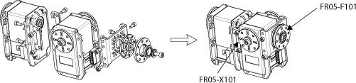
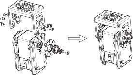
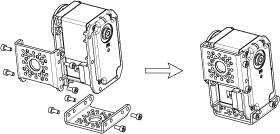
12 FR05-F101_FR05-X101 FR05-H101 FR05-S101 Horn The types of MX-64 Horn are as follows. HN05-N102 HN05-I101

13 Ref: place careful attention when aligning the horn of the RX-64 to prevent misalignment. Combination The following example shows the combination structure of option frames and horns. Dimension Drawing Information : Drawing Information : MX-64T MX-64R Frame Compatibility Guide(LINK) Videos HOW TO REPLACE GEARS
14 [ROBOTIS] FAQ-DYNAMIXEL Gear Replacement (MX 64/MX-106) Error Report Copyrights (c) 2010 ROBOTIS All rights reserved.
User Manual. 北京博创兴盛机器人技术有限公司 UPTECH Robotics. TEL: , FAX:Ext.828
 promotion CDS55xx User Manual Doc. Ver. Update Rev. Authorized by Remarks 1.0 2010-3-22 何裕德 徐俊辉 1.1 2010-3-27 计海锋 徐俊辉 Add Chapter 5 1.2 2010-4-22 何裕德 1.3 2010-8-17 Cid 徐俊辉 Revise Page 1 of 21 Thanks for
OC-Servo Electronics Technology Co.,Ltd
 ROBS-251 MANUEL Page 1 of 26 Chapter 1 Overview 1.1 Properties ROBS-251 is a robot servo developed and produced as a set of motor, servo drives, and modbus communication interface in an integrated servo
Mercury technical manual
 v.1 Mercury technical manual September 2017 1 Mercury technical manual v.1 Mercury technical manual 1. Introduction 2. Connection details 2.1 Pin assignments 2.2 Connecting multiple units 2.3 Mercury Link
Serial Bus Smart Control servo SCS15 Manual
 Serial Bus Smart Control servo SCS15 Manual Revision history date version Update content 2016.8.19 V1.01 1. Corrigendum amendment 2. add speed control parameters 2016.12.21 V1.02 Delete protocol content
H/W Specification MCU : ST CORTEX-M3 ( 72MHZ,32BIT) POSITION SENSOR : Contactless absolute encoder (12BIT,360 DEGREE) Maker : ams
 POSITION SENSOR : Contactless absolute encoder (12BIT,360 DEGREE) Maker : ams") H/W Specification MCU : ST CORTEX-M3 ( STM32F103C8 @ 72MHZ,32BIT) POSITION SENSOR : Contactless absolute encoder (12BIT,360 DEGREE) Maker : ams (www.ams.com), Part No : AS5045 Motor : Coreless Motor Baud
H/W Specification MCU : ST CORTEX-M3 ( STM32F103C8 @ 72MHZ,32BIT) POSITION SENSOR : Contactless absolute encoder (12BIT,360 DEGREE) Maker : ams (www.ams.com), Part No : AS5045 Motor : Coreless Motor Baud
About New FT-SCServo (Smart Control Servo)
") About New FT-SCServo (Smart Control Servo) FT-SCServo is meaning that Smart Control Servo was R&D and manufactured by FEETECH. SCServo can work at servo mode and wheel mode. The servo mode can be used
About New FT-SCServo (Smart Control Servo) FT-SCServo is meaning that Smart Control Servo was R&D and manufactured by FEETECH. SCServo can work at servo mode and wheel mode. The servo mode can be used
Pololu TReX Jr Firmware Version 1.2: Configuration Parameter Documentation
 Pololu TReX Jr Firmware Version 1.2: Configuration Parameter Documentation Quick Parameter List: 0x00: Device Number 0x01: Required Channels 0x02: Ignored Channels 0x03: Reversed Channels 0x04: Parabolic
B3M Series Software Manual Command Reference. Kondo Kagaku Co., Ltd. Ver
 B3M Series Software Manual Command Reference Kondo Kagaku Co., Ltd. Ver. 1.2.0.2 Disclaimer This manual is a reference manual of commands for communicating with the B3M Series. Copyrights and all other
DMM Technology Corp. DYN AC Servo Drive Modbus RTU Specification [DYNMB1-BL A ] Document Version 1.0A Published Sept 17, 2017
![DMM Technology Corp. DYN AC Servo Drive Modbus RTU Specification [DYNMB1-BL A ] Document Version 1.0A Published Sept 17, 2017](/thumbs/74/69785866.jpg "DMM Technology Corp. DYN AC Servo Drive Modbus RTU Specification [DYNMB1-BL A ] Document Version 1.0A Published Sept 17, 2017") DMM Technology Corp. DYN AC Servo Drive Modbus RTU Specification [DYNMB1-BL1645-10A ] Document Version 1.0A Published Sept 17, 2017 March 02, 2017 Version 1.0 1. Overview The DYN2 and DYN4 servo drive
DMM Technology Corp. DYN AC Servo Drive Modbus RTU Specification [DYNMB1-BL1645-10A ] Document Version 1.0A Published Sept 17, 2017 March 02, 2017 Version 1.0 1. Overview The DYN2 and DYN4 servo drive
Know your energy. Modbus Register Map EB etactica Power Bar
 Know your energy Modbus Register Map EB etactica Power Bar Revision history Version Action Author Date 1.0 Initial document KP 25.08.2013 1.1 Document review, description and register update GP 26.08.2013
Know your energy. Modbus Register Map EM etactica Power Meter
 Know your energy Modbus Register Map EM etactica Power Meter Revision history Version Action Author Date 1.0 Initial document KP 25.08.2013 1.1 Document review, description and register update GP 26.08.2013
Carbon Dioxide (Tiny CO2) Gas Sensor. Rev TG400 User Manual
 Gas Sensor. Rev TG400 User Manual") Carbon Dioxide (Tiny CO2) Gas Sensor Rev. 1.2 TG400 User Manual The TG400 measuring carbon dioxide (chemical formula CO2) is a NDIR (Non-Dispersive Infrared) gas sensor. As it is contactless, it has high
Carbon Dioxide (Tiny CO2) Gas Sensor Rev. 1.2 TG400 User Manual The TG400 measuring carbon dioxide (chemical formula CO2) is a NDIR (Non-Dispersive Infrared) gas sensor. As it is contactless, it has high
DMM Technology Corp. DYN AC Servo Drive CAN Specification [DYNCAN1-BL314-12A] Document Version 1.2A Published March 20, 2018
![DMM Technology Corp. DYN AC Servo Drive CAN Specification [DYNCAN1-BL314-12A] Document Version 1.2A Published March 20, 2018](/thumbs/91/107061491.jpg "DMM Technology Corp. DYN AC Servo Drive CAN Specification [DYNCAN1-BL314-12A] Document Version 1.2A Published March 20, 2018") DMM Technology Corp. DYN AC Servo Drive CAN Specification [DYNCAN1-BL314-12A] Document Version 1.2A Published March 20, 2018 March 20, 2017 Version 1.2 1. Overview The DYN servo drive follow standard CAN2.0A
DMM Technology Corp. DYN AC Servo Drive CAN Specification [DYNCAN1-BL314-12A] Document Version 1.2A Published March 20, 2018 March 20, 2017 Version 1.2 1. Overview The DYN servo drive follow standard CAN2.0A
USART Digital Compass Manual
 USART Digital Compass Manual General Description HMC1022-USART is a low cost plane digital compass module. The working principle is utilizing magnetoresistive sensor sensing the Earth's magnetic field
OrigamiSat-1. FM Down Link Data Format. (English version)
") OrigamiSat-1 FM Down Link Data Format (English version) Document# OP-S1-0115 Revision Ver. 1.3 Date 2019/01/11, revised on 2019/01/13 Name Tokyo Tech OrigamiSat-1 project team Revision history Date Version
OrigamiSat-1 FM Down Link Data Format (English version) Document# OP-S1-0115 Revision Ver. 1.3 Date 2019/01/11, revised on 2019/01/13 Name Tokyo Tech OrigamiSat-1 project team Revision history Date Version
ICS3.5 Software Manual Command Refarence
 ICS3.5 Software Manual Command Refarence KONDO KAGAKU CO.,LTD Aug, 2015 1st Edition Disclaimer This command reference has been released for reference purposes only. Therefore, it is used entirely at your
The rangefinder can be configured using an I2C machine interface. Settings control the
 Detailed Register Definitions The rangefinder can be configured using an I2C machine interface. Settings control the acquisition and processing of ranging data. The I2C interface supports a transfer rate
Applied Motion Products CANopen Manual
 Applied Motion Products CANopen Manual APPLIED MOTION PRODUCTS, INC. 920-0025 Rev. F (This page intentionally left blank) 920-0025 Rev. F 2 Introduction This manual describes Applied Motion Products CANopen
Cost efficient design Operates in full sunlight Low power consumption Wide field of view Small footprint Simple serial connectivity Long Range
 Cost efficient design Operates in full sunlight Low power consumption Wide field of view Small footprint Simple serial connectivity Long Range sweep v1.0 CAUTION This device contains a component which
Serial Servo Controller
 Document : Datasheet Model # : ROB - 1185 Date : 16-Mar -07 Serial Servo Controller - USART/I 2 C with ADC Rhydo Technologies (P) Ltd. (An ISO 9001:2008 Certified R&D Company) Golden Plaza, Chitoor Road,
User's Manual. ServoCenter 4.1. Volume 2: Protocol Reference. Yost Engineering, Inc. 630 Second Street Portsmouth, Ohio
 ServoCenter 4.1 Volume 2: Protocol Reference Yost Engineering, Inc. 630 Second Street Portsmouth, Ohio 45662 www.yostengineering.com 2002-2009 Yost Engineering, Inc. Printed in USA 1 Table of Contents
Cost efficient design Operates in full sunlight Low power consumption Wide field of view Small footprint Simple serial connectivity Long Range
 Cost efficient design Operates in full sunlight Low power consumption Wide field of view Small footprint Simple serial connectivity Long Range sweep v1.0 CAUTION This device contains a component which
ASCII Programmer s Guide
 ASCII Programmer s Guide PN/ 16-01196 Revision 01 April 2015 TABLE OF CONTENTS About This Manual... 3 1: Introduction... 6 1.1: The Copley ASCII Interface... 7 1.2: Communication Protocol... 7 2: Command
10 AMP, 38V, 3 PHASE MOSFET DC BRUSHLESS DIGITAL MOTOR CONTROLLER
 MIL-PRF-38534 AND 38535 CERTIFIED FACILITY AMP, 38V, 3 PHASE MOSFET DC BRUSHLESS 4366 DIGITAL MOTOR CONTROLLER M.S.KENNEDY CORP. FEATURES: 38 Volt Maximum Operating Motor Supply Voltage 55 Volt Absolute
Copley ASCII Interface Programmer s Guide
 Copley ASCII Interface Programmer s Guide PN/95-00404-000 Revision 4 June 2008 Copley ASCII Interface Programmer s Guide TABLE OF CONTENTS About This Manual... 5 Overview and Scope... 5 Related Documentation...
3V TRANSCEIVER 2.4GHz BAND
 3V TRANSCEIVER 2.4GHz BAND Rev. 2 Code: 32001271 QUICK DESCRIPTION: IEEE 802.15.4 compliant transceiver operating in the 2.4 GHz ISM band with extremely compact dimensions. The module operates as an independent
isma-b-w0202 Modbus User Manual GC5 Sp. z o.o. Poland, Warsaw
 isma-b-w0202 isma-b-w0202 Modbus User Manual GC5 Sp. z o.o. Poland, Warsaw www.gc5.com 1. Introduction... 4 2. Safety rules... 4 3. Technical specifications... 5 4. Dimension... 6 5. LED Indication...
Catalogue 1. Brief Description Product feature Typ. Circuit Block Diagram...
 - 1 - Catalogue 1. Brief Description... - 3-2. Product feature...- 3-3. Typ. Circuit... - 4-4. Block Diagram...- 4-5. Electronical Characters...- 5-6. Typical Application...- 6-7. Pin Description... -
UNWINDING THE AX-12+ COMMUNICATION PROTOCOL
 by Fred Eady UNWINDING THE AX-+ COMMUNICATION PROTOCOL n the discussion and hardware build-up that follows, our collective programming and hardware design/assembly efforts will be focused on the Microchip
B Robo Claw 2 Channel 25A Motor Controller Data Sheet
 B0098 - Robo Claw 2 Channel 25A Motor Controller Feature Overview: 2 Channel at 25A, Peak 30A Hobby RC Radio Compatible Serial Mode TTL Input Analog Mode 2 Channel Quadrature Decoding Thermal Protection
CT435. PC Board Mount Temperature Controller
 CT435 PC Board Mount Temperature Controller Features Two RTD temperature sensor inputs: Pt100 or Pt1000. Wide temperature sensing range: -70 C to 650 C. All controller features are configurable through
CDR-915 Data Radio Module INTEGRATOR S GUIDE
 CDR-915 Data Radio Module Coyote DataCom, Inc. 3941 Park Drive, Suite 20-266, El Dorado Hills, CA 95762 Tel. 916-933-9981 Fax 916-913-0951 www.coyotedatacom.com TABLE OF CONTENTS General Information and
B RoboClaw 2 Channel 30A Motor Controller Data Sheet
 B0098 - RoboClaw 2 Channel 30A Motor Controller (c) 2010 BasicMicro. All Rights Reserved. Feature Overview: 2 Channel at 30Amp, Peak 60Amp Battery Elimination Circuit (BEC) Switching Mode BEC Hobby RC
Integrated Servo Motor UCS57
 Integrated Servo Motor Introduction is a new generation of high performance digital integrated servo drive motor, which is a series of low voltage AC servo products integrated with AC servo motor and drive
Absolute multi-turn hollow shaft encoder BOMH Dignalizer SSI
 features high resolution multi-turn encoder up to - 8 bit single-turn - 8 bit multi-turn interface programmable permanent self-test reference point programmable general data voltage supply 5 VDC (05C)
ies-2309 Integrated Easy Servo
 Datasheet of the integrated easy servo motor ies-09 ies-09 Integrated Easy Servo Motor + Drive + Encoder, 0-0VDC, NEMA, 0.9Nm Features Easy servo control technology to combine advantages of open-loop stepper
General Description. The TETRIX MAX Servo Motor Expansion Controller features the following:
 General Description The TETRIX MAX Servo Motor Expansion Controller is a servo motor expansion peripheral designed to allow the addition of multiple servo motors to the PRIZM Robotics Controller. The device
Low Power with Long Range RF Module DATASHEET Description
 Wireless-Tag WT-900M Low Power with Long Range RF Module DATASHEET Description WT-900M is a highly integrated low-power half-'duplex RF transceiver module embedding high-speed low-power MCU and high-performance
CMPS09 - Tilt Compensated Compass Module
 Introduction The CMPS09 module is a tilt compensated compass. Employing a 3-axis magnetometer and a 3-axis accelerometer and a powerful 16-bit processor, the CMPS09 has been designed to remove the errors
BW-IMU200 Serials. Low-cost Inertial Measurement Unit. Technical Manual
 Serials Low-cost Inertial Measurement Unit Technical Manual Introduction As a low-cost inertial measurement sensor, the BW-IMU200 measures the attitude parameters of the motion carrier (roll angle, pitch
Modern Robotics Inc. Sensor Documentation
 Modern Robotics Inc. Sensor Documentation Version 1.4.3 December 11, 2017 Contents 1. Document Control... 3 2. Introduction... 4 3. Three-Wire Analog & Digital Sensors... 5 3.1. Program Control Button
TETRIX Servo Motor Expansion Controller Technical Guide
 TETRIX Servo Motor Expansion Controller Technical Guide 44560 Content advising by Paul Uttley. SolidWorks Composer and KeyShot renderings by Tim Lankford, Brian Eckelberry, and Jason Redd. Desktop publishing
Qik 2s12v10 User's Guide
 1 Overview 2 Contacting Pololu 3 Connecting the Qik 3a Power and Motor Connections 3b Logic Connections 3c Included Hardware 3d Jumpers 3e Indicator LEDs and Phases of Operation 3f Board Dimensions and
Qik 2s12v10 User's Guide
 Qik 2s12v10 User's Guide 1. Overview.................................................... 2 2. Contacting Pololu................................................ 4 3. Connecting the Qik...............................................
InfraStruXure Manager v4.x Addendum: Building Management System Integration
 InfraStruXure Manager v4.x Addendum: Building Management System Integration Introduction This addendum explains the integration of the APC InfraStruXure Manager Appliance with a Building Management System
CMPS11 - Tilt Compensated Compass Module
 CMPS11 - Tilt Compensated Compass Module Introduction The CMPS11 is our 3rd generation tilt compensated compass. Employing a 3-axis magnetometer, a 3-axis gyro and a 3-axis accelerometer. A Kalman filter
MS2711B Hand-Held Spectrum Analyzer
 MS2711B Hand-Held Spectrum Analyzer Programming Manual Hand-Held Spectrum Analyzer, for Measuring, Monitoring and Analyzing Signal Environments WARRANTY The Anritsu product(s) listed on the title page
HPVFP High Performance Full Function Vector Frequency Inverter
 Advanced User Manual HPVFP High Performance Full Function Vector Frequency Inverter HP VER 1.00 1. HPVFP Parameter Set Overview...3 1.1. About this section...3 1.2. Parameter Structure Overview...3 1.3.
NIBP2010 with SpO2. Non Invasive Blood Pressure OEM board NIBP with. PULSE OXIMETRY SpO 2. Hardware-Version : C Firmware-Version : 3.
 Non Invasive Blood Pressure OEM board NIBP 2010 with PULSE OXIMETRY SpO 2 Hardware-Version : C Firmware-Version : 3.44 Issued: L. Engel Approved: B. Tek Released: B. Tek Date: 24.01.17 Date : 24.01.17
Integrated Easy Servo
 ies 1706 Integrated Easy Servo Motor + Drive + Encoder, 18 32VDC, NEMA17, 0.6Nm Features Easy servo control technology to combine advantages of open loop stepper systems and brushless servo systems Closed
Device/PLC Connection Manuals
 Device/PLC Connection Manuals About the Device/PLC Connection Manuals Prior to reading these manuals and setting up your device, be sure to read the "Important: Prior to reading the Device/PLC Connection
Logosol Intelligent Hall-Servo Drive LS-173U Doc # / Rev. C, 02/12/2008
 Features Specially designed for control of brushless motors without encoder Hall-Servo and Encoder-Servo control modes Motors supported: - Brushless 60/120 commutated (AC) - Brush-commutated (DC) Up to
Tarocco Closed Loop Motor Controller
 Contents Safety Information... 3 Overview... 4 Features... 4 SoC for Closed Loop Control... 4 Gate Driver... 5 MOSFETs in H Bridge Configuration... 5 Device Characteristics... 6 Installation... 7 Motor
Logosol AC/DC Intelligent Servo Drive for Coordinated Control LS-174P
 Features Motors supported: - Panasonic A and S series - Brushless 60/120 commutated - Brush-commutated (DC) motors Output current - 12A peak, 8A continuous - 20A peak, 12A continuous 12 to 90V single power
LCC-10 Product manual
 LCC-10 Product manual Rev 1.0 Jan 2011 LCC-10 Product manual Copyright and trademarks Copyright 2010 INGENIA-CAT, S.L. / SMAC Corporation Scope This document applies to i116 motion controller in its hardware
Tire Temperature and Pressure Monitoring System - Datasheet
 The Izze-Racing wireless Tire Temperature and Pressure Monitoring System (TTPMS) consists of small, lightweight, wheel-mounted sensors and an equally small receiver with a built in pressure transducer
Trademarks & Copyright
 Smart Peripheral Controller Neo DC Motor 1.2A Trademarks & Copyright AT, IBM, and PC are trademarks of International Business Machines Corp. Pentium is a registered trademark of Intel Corporation. Windows
DA DA 26 Technical Specification. Page 1/27. Volz Servos GmbH & Co. KG servos.com
 1/27 DA 26 DA 26 30 5024 2/27 Content 1. General Description... 3 2. Operating Data... 4 3. Performance... 5 4. Command Signal... 6 4.1. PWM Command Interface... 6 4.2. RS 485 Command Signal... 6 4.3.
EE 314 Spring 2003 Microprocessor Systems
 EE 314 Spring 2003 Microprocessor Systems Laboratory Project #9 Closed Loop Control Overview and Introduction This project will bring together several pieces of software and draw on knowledge gained in
DMX-K-DRV-23 Integrated Step Motor Driver & Basic Controller
 DMX-K-DRV-23 Integrated Step Motor Driver & Basic Controller DMX-K-DRV-23 Manual - 1 - rev 1.35 COPYRIGHT 2013 ARCUS, ALL RIGHTS RESERVED First edition, June 2007 ARCUS TECHNOLOGY copyrights this document.
BV4112. Serial Micro stepping Motor Controller. Product specification. Dec V0.a. ByVac Page 1 of 18
 Product specification Dec. 2012 V0.a ByVac Page 1 of 18 SV3 Relay Controller BV4111 Contents 1. Introduction...4 2. Features...4 3. Electrical interface...4 3.1. Serial interface...4 3.2. Motor Connector...4
ROTRONIC HygroClip Digital Input / Output
 ROTRONIC HygroClip Digital Input / Output OEM customers that use the HygroClip have the choice of using either the analog humidity and temperature output signals or the digital signal input / output (DIO).
High Performance Microstep Systems
 P315/P315X High Performance Microstep Systems Description Common Features Torques from 65 to 3, oz-in. with speeds to 3, RPM continuous. Dip switch selectable resolutions up to 5,8 steps per revolution.
The "FISH" Quad Hand Sensor
 The "FISH" Quad Hand Sensor Physics and Media Group MIT Media Laboratory 20 Ames Street E15-022 Cambridge, Mass 02139-4307 (617) 253-2383 phm@media.mit.edu ** U S E R S G U I D E ********* TABLE OF CONTENTS
DMMDRV Software User Manual. Version: A10 50 / December 2015 Manual Code: DSFEN A
 DMMDRV Software User Manual Version: A10 50 / December 2015 Manual Code: DSFEN A1050 1215 Contents Section 1. General Software Safety Precautions 1.1 DYN2 System Safety 1.2 DYN4 System Safety 1.3 Servo
Logosol AC/DC Intelligent Servo Drive for Coordinated Control LS-174WP
 Features Motors supported: - Panasonic A and S series - Brushless 60/120 commutated - Brush-commutated (DC) motors Up to 20A peak, 12A continuous output current 12 to 90VDC power supply Separate motor
Drive CM User Manual
 The Best Choice for the Most Benefit! At LS Mecapion, we are committed to providing premium benefits to all of our customers. Drive CM User Manual Servo Configuration Tool Ver. 1.0 Safety Precautions -
Contents. USER MANUAL NI ISM-7400 Integrated Stepper
 USER MANUAL NI ISM-7400 Integrated Stepper This manual describes the NI ISM-7400 integrated stepper. It describes electrical and mechanical characteristics of the devices, as well as I/O functionality.
Medlab GmbH EG05000 User Manual. medlab. Five Lead ECG OEM board EG Technical Manual. Copyright Medlab Version Version 1.
 Medlab GmbH EG05000 User Manual medlab Five Lead ECG OEM board EG05000 Technical Manual Copyright Medlab 2016 1 Medlab GmbH EG05000 User Manual Medlab GmbH support@medlab.eu www.medlab.eu 2 Medlab GmbH
TOSVERT TM VF-nC3 Parameter List
 TOSVERT TM VF-nC Parameter List E658664 - Setting information * Please fill it in if necessary. Item Content Item Content Setting date / person Customer Application Application model Motor manufacturer
DMX-K-DRV-17 Integrated Step Motor Driver & Basic Controller
 DMX-K-DRV-17 Integrated Step Motor Driver & Basic Controller DMX-K-DRV-17 Manual - 1 - rev 1.35 COPYRIGHT 2015 ARCUS, ALL RIGHTS RESERVED First edition, June 2007 ARCUS TECHNOLOGY copyrights this document.
EtherCAT Expansion Chassis
 VENDOR CONFIGURATIONS GUIDE EtherCAT Expansion Chassis Deterministic Ethernet Expansion Chassis for C Series Modules This document contains information about accessing all of the functionality of the C
Mounting Dimensions. Overview. Installation. Specifications
 Overview Mounting Dimensions RageBridge 2 is a motor controller that can drive 2 channels of DC motors, using several types of inputs, in forward and reverse with no delay. It features signal-loss failsafes,
Catalog
 - 1 - Catalog 1. Description...- 3-2. Features...- 3-3. Application...- 3-4. Block Diagram...- 3-5. Electrical Characteristics... - 4-6. Operation... - 4-1) Power on Reset...- 4-2) Setting Mode... - 5-3)
Roland Kammerer. 13. October 2010
 Peripherals Roland Institute of Computer Engineering Vienna University of Technology 13. October 2010 Overview 1. Analog/Digital Converter (ADC) 2. Pulse Width Modulation (PWM) 3. Serial Peripheral Interface
Revision 1. March 21, ADC Operation Manual N 11 th St San Jose CA
 Revision 1 March 21, 2017 ADC Operation Manual www.mountztorque.com - 1080 N 11 th St San Jose CA 95112 408.292.2214 1 Index 1. Installation 3 1.1 Required PC specification 3 1.2 Software 3 2. Operation
HBS Series Hybrid Servos
 Hybrid Servos 46 Hybrid Servos From the stepper and servo, but surpass them in many applications! HBS Series Hybrid Servos Closed-loop, eliminates loss of synchronization The HBS series use an encoder
BASIC-Tiger Application Note No. 059 Rev Motor control with H bridges. Gunther Zielosko. 1. Introduction
 Motor control with H bridges Gunther Zielosko 1. Introduction Controlling rather small DC motors using micro controllers as e.g. BASIC-Tiger are one of the more common applications of those useful helpers.
5096 FIRMWARE ENHANCEMENTS
 Document Number A100745 Version No.: 4.4.1 Effective Date: January 30, 2006 Initial Release: September 19, 2005 1. Fixed display of logged memory date and time broken in version 4.3. 2. Allow time samples
ES86 Series Closed-loop Stepper Drive + Motor System (Drive+ Motor/Encoder)
") ES86 Series Closed-loop Stepper Drive + Motor System (Drive+ Motor/Encoder) Traditional stepper motor drive systems operate open loop providing position control without feedback. However, because of this,
ES86 Series Closed-loop Stepper Drive + Motor System (Drive+ Motor/Encoder) Traditional stepper motor drive systems operate open loop providing position control without feedback. However, because of this,
Compatible Products: LAC L12-SS-GG-VV-P L16-SS-GG-VV-P PQ12-GG-VV-P P16-SS-GG-VV-P T16-SS-GG-VV-P
 USB Control and Configuration of the LAC (Linear Actuator Control Board) Compatible Products: LAC L12-SS-GG-VV-P L16-SS-GG-VV-P PQ12-GG-VV-P P16-SS-GG-VV-P T16-SS-GG-VV-P This note provides further information
Raritan PX2/PX3 Modbus Interface
 Raritan PX2/PX3 Modbus Interface Contents Introduction 2 Supported Modbus Functions.. 2 Feature Set 2 Register Layout 3 Conventions 3 Holding Register Map 3 Coil Map. 4 Basic PDU Parameters 5 Peripheral
Technical data. General specifications. Linearity error ± 0.1 Electrical specifications Operating voltage U B
 Model Number SYNCHRON SERIELLES INTERFACE Features Very small housing Up to 32 Bit multiturn SSI interface Free of wear magnetic sampling High resolution and accuracy Description The ENA36IL series are
TARVOS-III REFERENCE MANUAL
 TARVOS-III REFERENCE MANUAL AMB8826 / 2609011X8100X VERSION 2.1 NOVEMBER 7, 2018 Revision history Manual version 1.1 FW version 1.0.0-2.0.0 HW version Notes Date 2.2 Initial version January 2017 2.0 2.1.0
Applications. Operating Modes. Description. Part Number Description Package. Many to one. One to one Broadcast One to many
 RXQ2 - XXX GFSK MULTICHANNEL RADIO TRANSCEIVER Intelligent modem Transceiver Data Rates to 100 kbps Selectable Narrowband Channels Crystal controlled design Supply Voltage 3.3V Serial Data Interface with
FLD00042 I 2 C Digital Ambient Light Sensor
 FLD00042 I 2 C Digital Ambient Light Sensor Features Built-in temperature compensation circuit Operating temperature: -30 C to 70 C Supply voltage range: 2.4V to 3.6V I 2 C serial port communication: Fast
Brushless DC Motor Controller Specification Assemblies 025F0248
 Brushless DC Motor Controller Specification Assemblies 025F0248 600A1099 Rev. B April 4 th, 2014 Revision History EC Date Description Rev EC54318 09/03/13 Initial Release A EC58093 04/04/14 Added cap discharge
Multi-function, Compact Inverters. 3G3MV Series
 Multi-function, Compact Inverters 3G3MV Series There has been a great demand for inverters with more functions and easier motor control than conventional i OMRON's powerful, compact 3G3MV Series with versat
Firmware Specification
 control EPOS Positioning Controller Edition April 2005 Positioning Controller Documentation 1 Table of contents 1 Table of contents... 2 2 Table of figures... 6 3 Table of tables... 7 4 Introduction...
2F. No.25, Industry E. 9 th Rd., Science-Based Industrial Park, Hsinchu, Taiwan Application Note of OGM220, AN001 V1.8
 Application Note of OGM220, AN001 V1.8 1.0 Introduction OGM220 series is a dual channels NDIR module having a digital output directly proportional to CO2 concentration. OGM220 is designed for multi-dropped
Integrity Instruments
 Integrity Instruments P.O. Box 451 Order Phone 800-450-2001 Pine River Minnesota Fax Phone 218-587-3414 56474 USA Tech Phone 218-587-3120 http://www.integrityusa.com 485M300 Series I/O Modules Digital
10.9. Serial communication parameters Motor parameters Paramters handling Status monitor
 Contents 1. Introduction... 4 1.1. About power supply for AU9290... 4 1.2. About applicable stepping motors... 4 1.3. About setting and storing of parameters... 5 1.4. About optional functions... 5 1.5.
EZ Stepper Command set and Communications protocol
 Command Set For Stepper Models: EZ17, EZHR17, EZHR23 Document Revision: A33 5/5/06 INDEX Command Set. Page 2 Programming Examples.. Page 9 Multi Axis Coordinated Motion.. Page 13 Stepper Motor Selection
BMS BMU Vehicle Communications Protocol
 BMS Communications Protocol 2013 Tritium Pty Ltd Brisbane, Australia http://www.tritium.com.au 1 of 11 TABLE OF CONTENTS 1 Introduction...3 2 Overview...3 3 allocations...4 4 Data Format...4 5 CAN packet
AC MHz OEM TRANSCEIVERS Specifications Subject to Change
 AC4790 900 MHz OEM TRANSCEIVERS Specifications Subject to Change User s Manual Version 1.3 11160 THOMPSON AVENUE LENEXA, KS 66219 (800) 492-2320 www.aerocomm.com wireless@aerocomm.com 1 DOCUMENT INFORMATION
BLE 4.0 Module ZBModule User Manual 1 / 15
 BLE 4.0 Module ZBModule User Manual 1 / 15 Bluetooth 4.0 BLE Introduction With only a ZBmodule module, you can make your products easily and conveniently interactive connect with the ipad, iphone and Android
ES86 Series Closed-loop Stepper Drive + Motor System (Drive+ Motor/Encoder)
") ES86 Series Closed-loop Stepper Drive + Motor System (Drive+ Motor/Encoder) Traditional stepper motor drive systems operate open loop providing position control without feedback. However, because of this,
ES86 Series Closed-loop Stepper Drive + Motor System (Drive+ Motor/Encoder) Traditional stepper motor drive systems operate open loop providing position control without feedback. However, because of this,
Simple Servo USER Instructions
 Simple Servo USER Instructions Version 1V2 Copyright 2003-2007 Active Robots Limited 10A New Rock Ind. Est., Newrock, Chilcompton, Somerset BA3 4JE UK Tel: +44(0)1761 239 267 Fax: +44(0)176 123 3162 www.active-robots.com
BLuAC5 Brushless Universal Servo Amplifier
 BLuAC5 Brushless Universal Servo Amplifier Description The BLu Series servo drives provide compact, reliable solutions for a wide range of motion applications in a variety of industries. BLu Series drives
Contents AC4790 TRANSCEIVER MODULE 1 EEPROM PARAMETERS 32 DIMENSIONS 36 SPECIFICATIONS 3 ORDERING INFORMATION 40 THEORY OF OPERATION 8
 VERSION 1.7 Contents AC4790 TRANSCEIVER MODULE 1 AC4790 features 1 Overview 1 SPECIFICATIONS 3 Pin Definitions 5 Electrical Specifications 7 THEORY OF OPERATION 8 Masterless Architecture 8 Modes of Operation