BLE 4.0 Module ZBModule User Manual 1 / 15
|
|
|
- Erica Reed
- 6 years ago
- Views:
Transcription

1 BLE 4.0 Module ZBModule User Manual 1 / 15
, FCC CFR47 15 parts (USA), and ARIB STD-T66")
2 Bluetooth 4.0 BLE Introduction With only a ZBmodule module, you can make your products easily and conveniently interactive connect with the ipad, iphone and Android phones with Bluetooth 4.0. ZBmodule Bluetooth 4.0 BLE module uses TI CC2540 chip, and is compatible with world-wide radio frequency regulation system: ETSI EN and EN class (Europe), FCC CFR47 15 parts (USA), and ARIB STD-T66 (Japan). ZBmodule can be used in many different areas: Consumer Medical Electronics Appliances intelligent control Remote control toy Sensor Data Acquisition Anti-lost alarm Wireless keyboard, mouse Remote control car Lighting control 2 / 15


3 Simple transparent communication ZBmodule Bluetooth 4.0 BLE module communicates with the MCU through the serial port in transparent communication mode. It is very easy to communicate with the MCU, you no longer need to worry about the development of the Bluetooth protocol stack. Flexible peripheral interface In addition to implementing a simple transparent communication protocol outside, ZBmodule module also has flexible peripheral interfaces; Through a special instruction, the APPs can dynamically change the mode on the IO port functionality, with ADC, PWM, IO, and UART interfaces. 3 / 15
; GFSK modulation mode; Transmitting power: 0 dbm to - 23 dbm; Receiving sensitivity - 93 DBM (1 MBPS); 1 MBPS")
; Range of remote control: line-of-sight")
4 Specifications of ZBmodule module: Working frequency 2.4 GHz (2402 MHZ to 2480 MHZ); GFSK modulation mode; Transmitting power: 0 dbm to - 23 dbm; Receiving sensitivity - 93 DBM (1 MBPS); 1 MBPS transmission rate maximum; Minimum working voltage of 2.0 V. Working voltage of 3.6 V ma in working mode; Standby current is less than 1 ua; Maximum current is 20 ma (sending data - 6 DBM); Range of remote control: line-of-sight communication range is 25 meters; Module size: 26.7 mm * 18.3 mm * 8.8 mm; PCB antenna/external antenna; Upgrade firmware through a serial port; 4 / 15
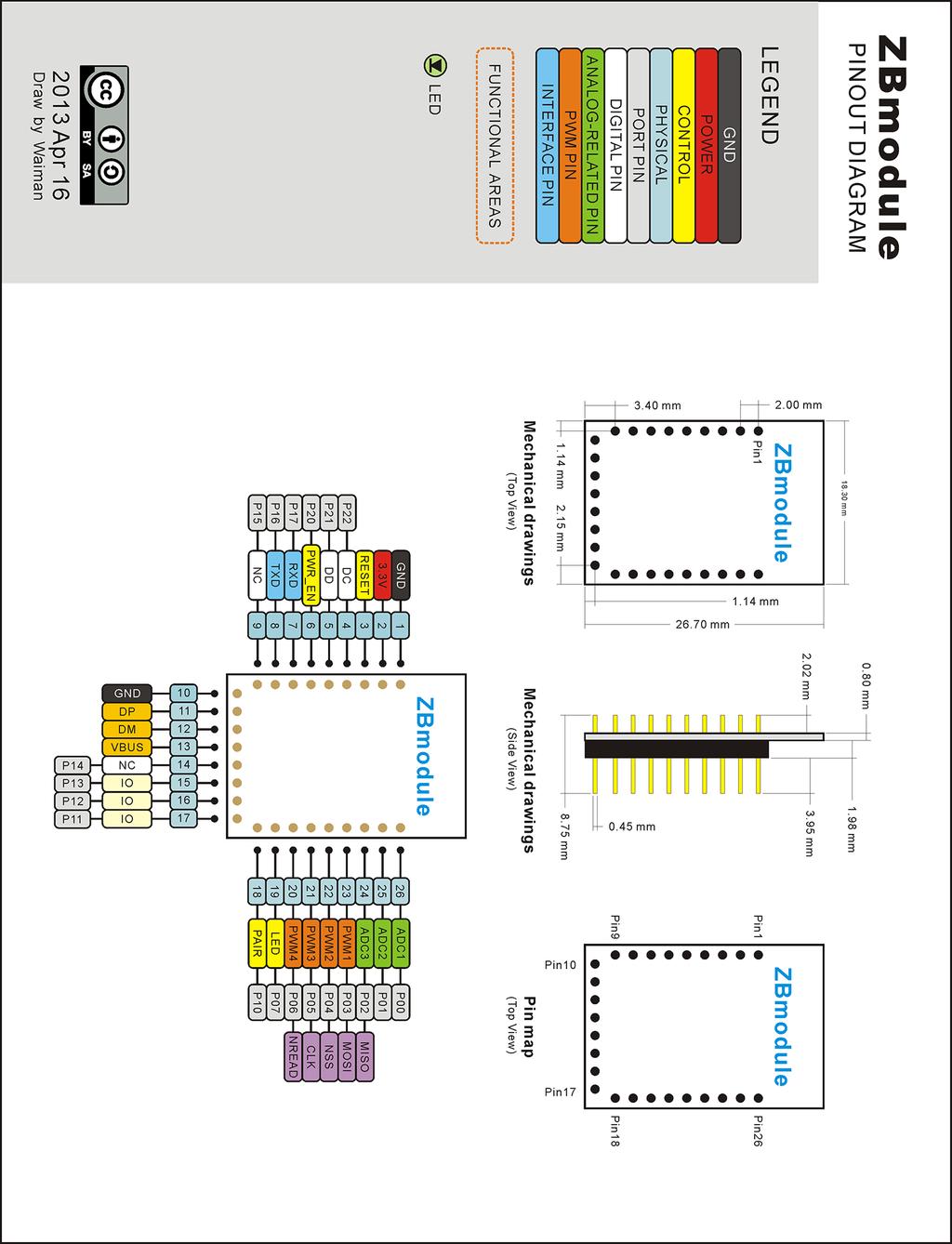
5 Pin Layout and Outline of ZB Module PIN# NAME Description 1 GND Ground 2 VCC 3.3V 3 RES Reset, Active Low 4 DC Debug Port 5 DD Debug Port 6 PWR_EN Awake, Active on Falling edge 7 UART_RX RX of UART 8 UART_TX TX of UART 9 NC Not connected 10 GND Ground 11 DP USB port 12 DN USB port 13 VBUS USB port 14 NC Not connected 15 IO Digital output (0V/3.3V) 16 IO Digital output (0V/3.3V) 17 IO Digital output (0V/3.3V) 18 PAIR Pair button, active low 19 LED Status LED 20 PWM4/SPI_NREAD PWM with adjustable frequency and duty cycle or SPI interface 21 PWM3/SPI_CLK PWM with adjustable frequency and duty cycle or SPI interface 22 PWM2/SPI_NSS PWM with adjustable frequency and duty cycle or SPI interface 23 PWM1/SPI_MOSI PWM with adjustable frequency and duty cycle or SPI interface 24 ADC/SPI_MISO PWM with adjustable frequency and duty cycle or SPI interface 25 ADC Analog Input (0-3.3V) 26 ADC Analog Input (0-3.3V) 5 / 15
6 Note: 1. Default baud rate: 9600bps, 8N1 2. PWM 1 and PWM 2 are with the same frequency, but the duty cycle can be different. Serial Protocol of ZBModule 1.1 Frame structure The serial protocol of ZBmodule is used to provide a communication between device (which is Arduino) and the ZBmodule. There are two different communication modes of the protocol: transparent communication mode and AT mode. Transparent mode: The size of the frame is 20 bytes (the first byte cannot be 0xA5). AT mode: There are 4 areas, preamble, length, payload, and CRC. It can be shown below: Segment Preamble Length (LEN) Payload CRC (CHS) Postamble (code) (PayLoad) (End) Byte 2 1 N 1 1 Preamble (code): 0xA5 0xA2 Length (LEN): Max 20 bytes Payload: the content of the package Postamble (End): 0x5A CRC: CHS= (PayLoad[0]+ + PayLoad[n-1])&0xFF; 1.2 Serial AT command: 0x00: Test Command When receive this command, the module will reply with: Device CMD OK 0xA5 0xA2 0x01 0x00 0x00 0x5A 6 / 15
7 0x02: Serial baud rate configuration When receive this command, if successfully, the module will acknowledge with: Change Baud to XXX OK. Otherwise, it will reply with: Error Baud Set Option From 0x00 to 0x05. Sample command to set baud rate to 9600bps, 8N1: 0xA5 0xA2 0x02 0x02 0x00 0x02 0x5A There are 5 settings: 0x bps, 8N1 0x bps, 8N1 0x bps, 8N1 0x bps, 8N1 0x bps, 8N1 0x03: Reset the module When receive this command, the module will reply with: Reset after 1000ms 0xA5 0xA2 0x02 0x03 0x03 0x5A 0x04: Configure the pairing status of the module When receive this command, the module will reply with: Pair Permit =False or Pair Permit =True. 7 / 15
8 0xA5 0xA2 0x02 0x04 0x00 or 0x01 0x04 or 0x05 0x5A When set with 0x00, the module will be in a pair non-permit state. When set with 0x01, the module will be in a pair permit state. 0x05: Disconnect the module When receive this command, the module will reply with: Pair Permit =False or Pair Permit =True. 0xA5 0xA2 0x02 0x04 0x00 or 0x01 0x04 or 0x05 0x5A When set with 0x00, the module will be in a pair non-permit state. When set with 0x01, the module will be in a pair permit state. 0x06: RSSI Detection This command is used to detect the signal strength (It can be used to measure the distance). 0xA5 0xA2 0x02 0x06 0x06 0x5A It will 8 / 15
9 BLE Protocol 2.1 BLE Frame structure The BLE protocol is used to establish the communication between devices such as iphone to the ZBmodule. There are two different communication modes of the protocol: transparent communication mode and AT mode. Transparent mode: The size of the frame is 20 bytes (the first byte cannot be 0xA5). AT mode: There are 4 areas, preamble, length, payload, and CRC. It can be shown below: Segment Preamble Length (LEN) Payload CRC (CHS) Postamble (code) (PayLoad) (End) Byte 2 1 N 1 1 Preamble (code): 0xA5 0xA3 Length (LEN): Max 20 bytes Payload: the content of the package Postamble (End): 0x5A CRC: CHS= (PayLoad[0]+ + PayLoad[n-1])&0xFF; 0x00: Reset Module When the remote device such as iphone sends this command to the module, the module will automatically terminate the connection with the remote device. 0xA5 0xA3 0x01 0x00 0x00 0x5A 0x01: Set Frequency of PWM The remote device such as iphone can use this command to configure the output frequency of the ZBmodule PWMs (The default PWM frequency is 1K Hz.) 9 / 15
10 0xA5 0xA3 0x05 0x01 PWMF_1 PWMF_2 PWMF_3 PWMF_4 0xXX 0x5A PWM_FREQ=PWMF_1 <<24 PWMF_2<<16 PWMF_3 <<8 PWMF_4; These two bytes form the value of the frequency. 0xA5 0xA3 0x05 0x01 0x00 0x04 0x93 0xE0 0x78 0x5A The frequency of the PWM is configured to be 300k (0x000494e0). 0x02: Set Duty Cycle of PWM The remote device such as iphone can use this command to configure the duty cycle of PWM of the ZBmodule. The range of the duty cycle is 1% - 99%. 0xA5 0xA3 0x03 0x02 PWM_CH PWM_DUTY 0xXX 0x5A PWM_CH (1<=PWM_CH<=4) is the channel number of the PWM. PWM_DUTY (1<=PWMOCCUPT<=99) is the duty cycle. 0xA5 0xA3 0x03 0x02 0x02 0x44 0x48 0x5A The above command will configure the duty cycle of the PWM channel No. 2 to be 68%. 0x03: Set Status of GPIO Channel The remote device such as iphone can use this command to set the status of GPIO channel. 0xA5 0xA3 0x03 0x03 GPIO_CH GPIO_STATUS 0xXX 0x5A GPIO_CH (1<=GPIO_CH <=4) is the channel number of GPIO. GPIO_STATUS : 0 means low level output, and 1 means high level output. 10 / 15
11 0xA5 0xA3 0x03 0x03 0x02 0x01 0x06 0x5A The above command will set the GPIO channel 2 to output high level. 0x04: Read Voltage of AIO The remote device such as iphone can use this command to read the voltage of AIO channel. 0xA5 0xA3 0x02 0x04 AIO_CH 0xXX 0x5A AIO_CH (1<=AIO_CH<=3 ) is the ADC channel number. 0x0C: Configure the baud rate of the serial port This command is similar to the serial interface command except that this command is used to remotely configure the serial port of the ZBmodule from the remote device such as iphone. Command: 0xA5 0xA3 0x02 0x0C BAUD 0xXX 0x5A BAUD is the serial port setting. There are 5 baud rate settings: 0x bps, 8N1 0x bps, 8N1 0x bps, 8N1 0x bps, 8N1 0x bps, 8N1 11 / 15
12 0xA5 0xA3 0x02 0x0C 0x00 0x02 0x5A This command configures the serial port to be 9600bps, 8N1. 0x0f: Query the baud rate of the serial port This command is similar to the serial interface command except that this command is used to remotely query the serial port of the ZBmodule from the remote device such as iphone. Command: 0xA5 0xA3 0x01 0x0f 0x0f 0x5A This command is used to query the setting of the serial port, and the results will be sent to the remote device such as iphone after 200ms. 0xA5 0xB3 0x02 0x0f BAUD 0xXX 0x5A BAUD is the baud rate. There are 5 setting: 0x bps, 8N1 0x bps, 8N1 0x bps, 8N1 0x bps, 8N1 0x bps, 8N1 0x0d: Save the current setting of GPIO This command is used remotely to save the current setting of GPIO, so that the GPIO status can be restored after power cycle. This function is mainly useful for lighting control. 12 / 15
13 0xA5 0xA3 0x01 0x0d 0x0d 0x5A 0x0e: Save the current setting of PWM This command is used remotely to save the current setting of PWM, so that the PWM status can be restored after power cycle. One typical application of this function is the RGB control of LEDs. 0xA5 0xA3 0x01 0x0e 0x0e 0x5A 0x10: Clear the settings of the ZBmodule (including serial port setting, PWM setting, GPIO setting) 0xA5 0xA3 0x01 0x10 0x10 0x5A After this command is executed, the serial port is restored to be 9600bps, 8N1. GPIOs will be all low level, and duty cycle of PWM will be 0 (i.e, no output). Complementary Commands: 0x05: Control 4 PWMS at the same time 0xA5 0xA3 0x06 0x05 CHMsk CH1_Duty CH2_Duty CH3_Cuty CH4_Duty 0xXX 0x5A CHMsk is the mask of the PWM channels. We can define multiple channel outputs by output=ch1 Ch2 Ch3 Ch4. Ch1: 0x01 Ch2: 0x02 Ch3: 0x04 13 / 15
14 Ch4: 0x08 Set No.1, No.2 and No.4 of PWM to have a duty cycle of 20%, 30%, and 40%. 0xA5 0xA3 0x06 0x05 0x0B 0x14 0x1E 0x00 0x28 0x6A 0x5A 0x06: Control 4 GPIOs at the same time 0xA5 0xA3 0x06 0x06 IOMask GPIO1_Status GPIO2_Status GPIO3_Status GPIO4_Status 0xXX 0x5A IOMask is the mask of the GPIO channels. We can define multiple channel outputs by output=gpio1 GPIO2 GPIO3 GPIO4. GPIO1: 0x01 GPIO2: 0x02 GPIO3:0x04 GPIO4:0x08 Set No.1, No.2 and No.4 of GPIOs to be high level. 0xA5 0xA3 0x06 0x06 0x0B 0x01 0x01 0x00 0x01 0x14 0x5A The above two commands can be used with the commands saving the status of PWMs and GPIOs. It can be used to control LED or servo. 14 / 15
15 15 / 15
Catalog
 - 1 - Catalog 1. Description...- 3-2. Features...- 3-3. Application...- 3-4. Block Diagram...- 3-5. Electrical Characteristics... - 4-6. Operation... - 4-1) Power on Reset...- 4-2) Setting Mode... - 5-3)
RF4432 wireless transceiver module
 1. Description www.nicerf.com RF4432 RF4432 wireless transceiver module RF4432 adopts Silicon Lab Si4432 RF chip, which is a highly integrated wireless ISM band transceiver. The features of high sensitivity
3V TRANSCEIVER 2.4GHz BAND
 3V TRANSCEIVER 2.4GHz BAND Rev. 2 Code: 32001271 QUICK DESCRIPTION: IEEE 802.15.4 compliant transceiver operating in the 2.4 GHz ISM band with extremely compact dimensions. The module operates as an independent
Low Power with Long Range RF Module DATASHEET Description
 Wireless-Tag WT-900M Low Power with Long Range RF Module DATASHEET Description WT-900M is a highly integrated low-power half-'duplex RF transceiver module embedding high-speed low-power MCU and high-performance
AO-1505-THM ZigBee Temperature and Humidity Sensor
 Features Reliable wireless transceiver module. Compatible with Peer to Peer, Star, Tree, or Mesh network configurations. AO-50 with on board PCB ANT with 50M range (LOS). AO-50A with external Antenna.
RFBee User Manual v1.0
 RFBee User Manual v1.0 Index RFBee... 1 Overview... 2 Specifications... 3 Electrical Characterstics... 3 System Block Diagram... 4 Microprocessor-Atmega168... 4 RF Transceiver-CC1101... 4 Hardware Installation...
RF NiceRF Wireless Technology Co., Ltd. Rev
 - 1 - Catalog 1. Description...- 3-2. Features...- 3-3. Application...- 3-4. Electrical Specifications...- 4-5. Schematic...- 4-6. Pin Configuration...- 5-7. Antenna... - 6-8. Mechanical dimensions(unit:
Catalog
 Catalog 1. Description... - 3-2. Features... - 3-3. Application... - 3-4. Electrical specifications...- 4-5. Schematic... - 4-6. Pin Configuration... - 5-7. Antenna... - 6-8. Mechanical Dimension(Unit:
BluetoothMesh ModuleDatasheet
 BluetoothMesh ModuleDatasheet (WS_D02_8266_V2.2) Shenzhen WE SMART Electronics Co., Ltd Website:www.we smart.cn Mailbox:business@we smart.cn Address:7th FL,Bldg 2B,Wu tong dao industrial park,hangkong
Single Chip High Performance low Power RF Transceiver (Narrow band solution)
") Single Chip High Performance low Power RF Transceiver (Narrow band solution) Model : Sub. 1GHz RF Module Part No : TC1200TCXO-PTIx-N Version : V1.2 Date : 2013.11.11 Function Description The TC1200TCXO-PTIx-N
Single Chip High Performance low Power RF Transceiver (Narrow band solution) Model : Sub. 1GHz RF Module Part No : TC1200TCXO-PTIx-N Version : V1.2 Date : 2013.11.11 Function Description The TC1200TCXO-PTIx-N
Catalogue
 Catalogue 1. Overview... - 3-2. Features... - 3-3. Applications...- 3-4. Electrical Characteristics...- 4-5. Schematic... - 4-6. Speed rate correlation table...- 6-7. Pin definition...- 6-8. Accessories...-
LoRa1278 Wireless Transceiver Module
 LoRa1278 Wireless Transceiver Module 1. Description LoRa1278 adopts Semtech RF transceiver chip SX1278, which adopts LoRa TM Spread Spectrum modulation frequency hopping technique. The features of long
802.11g Wireless Sensor Network Modules
 RFMProducts are now Murata Products Small Size, Integral Antenna, Light Weight, Low Cost 7.5 µa Sleep Current Supports Battery Operation Timer and Event Triggered Auto-reporting Capability Analog, Digital,
RF4463F30 High Power wireless transceiver module
 RF4463F30 High Power wireless transceiver module 1. Description RF4463F30 adopts Silicon Lab Si4463 RF chip, which is a highly integrated wireless ISM band transceiver chip. Extremely high receive sensitivity
SNIOT702 Specification. Version number:v 1.0.1
 Version number:v 1.0.1 Catelog 1 Product introduction... 1 1.1 Product introduction... 1 1.2 Product application... 1 1.3 Main characteristics... 2 1.4 Product advantage... 3 2 Technical specifications...
LoRa1276 Catalogue
 Catalogue 1. Overview... 3 2. Features... 3 3. Applications... 3 4. Electrical Characteristics... 4 5. Schematic... 5 6. Speed rate correlation table... 6 7. Pin definition... 6 8. Accessories... 8 9.
DRF4432D20 20dBm ISM RF Transceiver Module V1.21
 DRF4432D dbm ISM RF Transceiver Module V1.21 Features GFSK transceiver Module ISM frequency bands 19.2K bps data rate Multiple channels dbm Max. output power Baud rate configurable 256 bytes data buffer
Applications. Operating Modes. Description. Part Number Description Package. Many to one. One to one Broadcast One to many
 RXQ2 - XXX GFSK MULTICHANNEL RADIO TRANSCEIVER Intelligent modem Transceiver Data Rates to 100 kbps Selectable Narrowband Channels Crystal controlled design Supply Voltage 3.3V Serial Data Interface with
Embedded Radio Data Transceiver SV611
 Embedded Radio Data Transceiver SV611 Description SV611 is highly integrated, multi-ports radio data transceiver module. It adopts high performance Silicon Lab Si4432 RF chip. Si4432 has low reception
RF1212 RF1212 Ultra-low Power ISM Transceiver Module V2.0
 RF1212 Ultra-low Power ISM Transceiver Module V2.0 Application: Features: Home automation Security alarm Telemetry Automatic meter reading Contactless access Wireless data logger Remote motor control Wireless
LORA1278F30 Catalogue
 Catalogue 1. Overview... 3 2. Feature... 3 3. Application... 3 4. Block Diagram... 4 5. Electrical Characteristics... 4 6. Schematic... 5 7. Speed rate correlation table... 6 8. Pin definition... 6 9.
LORA1276F30 Catalogue
 Catalogue 1. Overview... 3 2. Feature... 3 3. Application... 3 4. Block Diagram... 4 5. Electrical Characteristics... 4 6. Schematic... 5 7. Speed rate correlation table... 6 8. Pin definition... 6 9.
RF7129 Ultra-low power Tranceiver module V2.0
 1. General RF7129 series is a low cost, ultra-low power, high performance transparent two way semi-duplex GFSK transceiver with operation at 433/470/868/915 Mhz. It integrates with high speed MCU from
SV613 USB Interface Wireless Module SV613
 USB Interface Wireless Module SV613 1. Description SV613 is highly-integrated RF module, which adopts high performance Si4432 from Silicon Labs. It comes with USB Interface. SV613 has high sensitivity
RN-41. Class 1 Bluetooth Module. Features. Applications. Description. Block Diagram. DS-RN41-V3.
 RN-41 www.rovingnetworks.com DS--V3.1 11/13/2009 Class 1 Bluetooth Module Features Fully qualified Bluetooth 2.1/2.0/1.2/1.1 module Bluetooth v2.0+edr support Postage stamp sized form factor, 13.4mm x
E70-433MS14 Datasheet v1.1
 E70-433MS14 Datasheet v1.1 Contents 1. Introduction... 2 2. Features... 3 3. E70 Series... 3 4. Electrical Parameter... 4 5. UART Functional description (default)... 5 5.1 Fixed transmission... 5 5.2 Broadcast
Characteristic Sym Notes Minimum Typical Maximum Units Operating Frequency Range MHz. RF Chip Rate 11 Mcps RF Data Rates 1, 2, 5.
 RFM Products are now Murata products. Small Size, Light Weight, Low Cost 7.5 µa Sleep Current Supports Battery Operation Timer and Event Triggered Auto-reporting Capability Analog, Digital, Serial and
VT-CC2530-Z1 Wireless Module. User Guide
 Wireless Module User Guide V-CHIP MICROSYSTEMS Co. Ltd Address: Room 612-613, Science and Technology Service Center Building, NO.1, Qilin Road, Nanshan District, Shenzhen, Guangdong TEL:0755-88844812 FAX:0755-22643680
Catalog
 - 1 - Catalog 1. Overview... - 3-2. Feature...- 3-3. Application... - 3-4. Block Diagram... - 3-5. Electrical Characteristics...- 4-6. Operation...- 4-1) Power on Reset... - 4-2) Sleep mode...- 4-3) Working
RF4432PRO wireless transceiver module
 wireless transceiver module RF4432PRO 1. Description RF4432PRO adopts Silicon Lab Si4432 RF chip, which is a highly integrated wireless ISM band transceiver chip. Extremely high receive sensitivity (-121
RN-21. Class 1 Bluetooth Module. Applications. Features. Description. Block Diagram. DS-RN21-V2 3/25/2010
 RN-21 www.rovingnetworks.com DS-RN21-V2 3/25/2010 Class 1 Bluetooth Module Features Supports Bluetooth 2.1/2.0/1.2/1.1 standards Class1, up to 15dBm(RN21) (100meters) Bluetooth v2.0+edr support Postage
Catalog
 - 1 - Catalog 1. Overview...- 3-2. Feature... - 3-3. Application...- 3-4. Block Diagram...- 3-5. Electrical Characteristics... - 4-6. Operation... - 4-1) Power on Reset... - 4-2) Sleep mode... - 4-3) Working
JDY-08 Bluetooth transparent transmission module
 TAG: JDY-08 Bluetooth LE BLE HM-10 HM-11 AT-09 CC41-A Original Reference (Chinese) : http://pan.baidu.com/s/1jidemdw http://www.cnledw.com/inter/upload/2016072916504828280.pdf https://pan.baidu.com/s/1nvanmex
DISCONTINUED. Modulation Type Number of RF Channels 15
 RFM Products are now Murata products. 2.4 GHz Spread Spectrum Transceiver Module Small Size, Light Weight, Built-In Antenna Sleep Current less than 3 µa FCC, Canadian IC and ETSI Certified for Unlicensed
RF ISM Transparent Transceiver Module V4.0
 RF7020-27 ISM Transparent Transceiver Module V4.0 Overview: RF7020-27 is highly integrated semi-duplex medium power transceiver module with high speed MCU and high performance RF IC. Utilizing high efficiency
RN-42. Class 2 Bluetooth Module. Features. Description. Applications. Block Diagram. DS-RN42-V1.1 1/12/2010.
 www.rovingnetworks.com DS-RN42-V1.1 1/12/2010 Class 2 Bluetooth Module Features Fully qualified Bluetooth 2.1/2.0/1.2/1.1 module Bluetooth v2.0+edr support Postage stamp sized form factor, 13.4mm x 25.8
Characteristic Sym Notes Minimum Typical Maximum Units Operating Frequency Range MHz Operating Frequency Tolerance khz
 DEVELOPMENT KIT (Info Click here) 2.4 GHz ZigBee Transceiver Module Small Size, Light Weight, Low Cost Sleep Current less than 3 µa FCC and ETSI Certified for Unlicensed Operation The ZMN2405 2.4 GHz transceiver
Catalogue
 - 1 - Catalogue 1. Description... - 3-2. Features... - 3-3. Applications...- 3-4. Block Diagram... - 3-5. Electrical Characteristics...- 4-6. Operation...- 5 - Power on Reset... - 5 - Working mode... -
Characteristic Sym Notes Minimum Typical Maximum Units Operating Frequency Range MHz Operating Frequency Tolerance khz
 DEVELOPMENT KIT (Info Click here) 2.4 GHz ZigBee Transceiver Module Small Size, Light Weight, +18 dbm Transmitter Power Sleep Current less than 3 µa FCC and ETSI Certified for Unlicensed Operation The
RF4432F27 Catalog
 Catalog 1. Description... 3 2. Features... 3 3. Application... 3 4. Electrical Specifications... 4 5. Typical application circuit... 4 6. Pin definition... 5 7. Accessories... 6 8. Mechanical dimension...
VT-CC M Wireless Module. User Guide
 Wireless Module User Guide V-CHIP MICROSYSTEMS Co. Ltd Address: Room 612-613, Science and Technology Service Center Building, NO.1, Qilin Road, Nanshan District, Shenzhen, Guangdong TEL:0755-88844812 FAX:0755-22643680
DASL 120 Introduction to Microcontrollers
 DASL 120 Introduction to Microcontrollers Lecture 2 Introduction to 8-bit Microcontrollers Introduction to 8-bit Microcontrollers Introduction to 8-bit Microcontrollers Introduction to Atmel Atmega328
VT-DTMSA5-433M RF Transceiver Module User s guide
 RF Transceiver Module User s guide V-Chip Microsystems, Inc Add:6 floor, Longtang Building, Nan Shan Cloud Valley Innovation Industrial Park, No.1183, Liuxian Road, Nanshan District, Shenzhen city Tel:86-755-88844812
SMARTALPHA RF TRANSCEIVER
 SMARTALPHA RF TRANSCEIVER Intelligent RF Modem Module RF Data Rates to 19200bps Up to 300 metres Range Programmable to 433, 868, or 915MHz Selectable Narrowband RF Channels Crystal Controlled RF Design
SV-MESH Mesh network series Catalogue
 Catalogue 1. Description... 3 2. Features... 3 3. Applications... 3 4. Block Diagram... 4 5. Electrical Characteristics... 5 6. Operation... 5 Power on Reset... 5 Working mode... 6 Router mode... 8 Setting
868MHz HumDT TM Series RF Transceiver Module Data Guide
 868MHz HumDT TM Series RF Transceiver Module Data Guide ! Warning: Some customers may want Linx radio frequency ( RF ) products to control machinery or devices remotely, including machinery or devices
HC-12 Wireless Serial Port Communication Module
 HC-12 Wireless Serial Port Communication Module User Manual version 2.3C (updated from v1.1 English and v2.3 Chinese) Product Applications Wireless sensor Community building security Robot wireless control
Training Schedule. Robotic System Design using Arduino Platform
 Training Schedule Robotic System Design using Arduino Platform Session - 1 Embedded System Design Basics : Scope : To introduce Embedded Systems hardware design fundamentals to students. Processor Selection
RF1276 Long Distance Transceiver module V2.0
 1. General RF1276 series is a low cost, ultra-low power, high performance transparent two way semi-duplex LoRa modulation transceiver with operation at 169/433/868/915 Mhz. It integrates with high speed
USB Port Medium Power Wireless Module SV653
 USB Port Medium Power Wireless Module SV653 Description SV653 is a high-power USB interface integrated wireless data transmission module, using high-performance Silicon Lab Si4432 RF chip. Low receiver
E31-TTL-500 Datasheet V Feature E31-TTL-500
 E31-TTL-500 Datasheet V1.0.1.Introduction E31-TTL-500 1.1 Feature E31-TTL-500 E31-TTL-500 is a 500mW wireless transceiver module with narrow-band transmission, operates at 425-450.5MHz (default: 433MHz),
DRF4463D20 Medium Power ISM RF Transceiver Module V1.21
 DRF4463D20 Medium Power ISM RF Transceiver Module V1.21 Features GFSK transceiver Module 433Mhz ISM frequency band 40Kbps RF data rate Multiple channels 20dBm Max. output power -121dBm sensitivity @1k
Catalog
 - 1 - Catalog 1. Description... - 3-2. Features... - 3-3. Application... - 3-4. Schematic... - 3-5. Electrical Specifications...- 4-6. Pin Definition... - 4-7. Antenna... - 5-8. Mechanical Dimension...-
Catalogue 1. Brief Description Product feature Typ. Circuit Block Diagram...
 - 1 - Catalogue 1. Brief Description... - 3-2. Product feature...- 3-3. Typ. Circuit... - 4-4. Block Diagram...- 4-5. Electronical Characters...- 5-6. Typical Application...- 6-7. Pin Description... -
HumDT TM Series RF Transceiver Module Data Guide
 HumDT TM Series RF Transceiver Module Data Guide ! Warning: Some customers may want Linx radio frequency ( RF ) products to control machinery or devices remotely, including machinery or devices that can
LR1276 Module Datasheet V1.0
 LR1276 Module Datasheet V1.0 Features LoRaTM Modem 168 db maximum link budget +20 dbm - 100 mw constant RF output vs. V supply +14 dbm high efficiency PA Programmable bit rate up to 300 kbps High sensitivity:
MY-ZB010C UART to ZigBee Module
 MY-ZB010C UART to ZigBee Module Product Overview The MY-ZB010C is an industrial UART to ZigBee module designed by MYIR for applications which require low cost, low power, high reliability and far distance
DRF7020D20 20dBm ISM RF Transceiver Module V1.31
 DRF7020D20 20dBm ISM RF Transceiver Module V1.31 Features GFSK transceiver Module 433Mhz ISM frequency band 19.2K bps data rate Multiple channels 20dBm Max. output power Baud rate configurable 256 bytes
RN-42/RN-42-N Data Sheet
 www.rovingnetworks.com DS-RN42-V1.0 2/17/2010 Class 2 Bluetooth Module Features Fully qualified Bluetooth 2.1/2.0/1.2/1.1 module Bluetooth v2.0+edr support Available with on board chip antenna (RN- 42)
DRF7020D13 13dBm ISM RF Transceiver Module
 3dBm ISM RF Transceiver Module V2.2 Features Application GFSK transceiver Module 433Mhz ISM frequency band 9.6K bps FSK data rate Multiple channels 3dBm Max. output power Baud rate configurable 256 bytes
DNT2400. Low Cost 2.4 GHz FHSS Transceiver Module with I/O
 2.4 GHz Frequency Hopping Spread Spectrum Transceiver Point-to-point, Point-to-multipoint, Peer-to-peer and Tree-routing Networks Transmitter Power Configurable from 1 to 63 mw RF Data Rate Configurable
DRF1278F 20dBm LoRa Long Range RF Front-end Module V1.11
 20dBm LoRa Long Range RF Front-end Module V1.11 Features: Frequency Range: 433MHz Modulation: FSK/GFSK/MSK/LoRa SPI Data Interface Sensitivity: -139dBm Output Power: +20dBm Data Rate:
DISCONTINUED. Modulation Type Number of RF Channels 15
 RFM products are now Murata Products 2.4 GHz Spread Spectrum Transceiver Module Small Size, Light Weight, Low Cost Sleep Current less than 3 µa FCC, Canadian IC and ETSI Certified for Unlicensed Operation
Preliminary GHz Transceiver-µController-Module. Applications PRODUCT SPECIFICATION FEATURES MICROCONTROLLER MHz
 PRODUCT SPECIFICATION 2.4 2.5 GHz e Applications 6 : 2 " 2! 2 2 + 2 7 + + Alarm and Security Systems Video Automotive Home Automation Keyless entry Wireless Handsfree Remote Control Surveillance Wireless
Catalogue
 - 1 - Catalogue 1. Description...- 3-2. Features...- 3-3. Application...- 3-4. Block Diagram...- 4-5. Typical Schematic Circuit...- 4-6. Electrical Characteristics... - 5-7. Interface specification...-
Purchase the sample: E51-TTL-500 Datasheet V Feature E51-TTL-500
 E51-TTL-500 Datasheet V1.0.1.Introduction E51-TTL-500 1.1 Feature E51-TTL-500 E51-TTL-500 is a 500mW wireless transceiver module(uart), with transparent transmission, operates at 225-237.6MHz z(default
Pololu TReX Jr Firmware Version 1.2: Configuration Parameter Documentation
 Pololu TReX Jr Firmware Version 1.2: Configuration Parameter Documentation Quick Parameter List: 0x00: Device Number 0x01: Required Channels 0x02: Ignored Channels 0x03: Reversed Channels 0x04: Parabolic
G3P-R232. User Manual. Release. 2.06
 G3P-R232 User Manual Release. 2.06 1 INDEX 1. RELEASE HISTORY... 3 1.1. Release 1.01... 3 1.2. Release 2.01... 3 1.3. Release 2.02... 3 1.4. Release 2.03... 3 1.5. Release 2.04... 3 1.6. Release 2.05...
VT-CC1110PA-433M. Wireless Module. User Guide
 Wireless Module User Guide V-Chip Microsystems, Inc Add:6 floor, Longtang Building, Nan Shan Cloud Valley Innovation Industrial Park, No.1183, Liuxian Road, Nanshan District, Shenzhen city Tel:86-755-88844812
Bluetooth low energy CC2541 ibeacon module. Datasheet
 Bluetooth low energy CC254 ibeacon module Datasheet 204 Table of contents. Description...3 2. Features...3 3. ibeacon parameter default setting...3 4. Modify ibeacon parameter...4 5. Electronic parameters...7
BlinkRC User Manual. 21 December Hardware Version 1.1. Manual Version 2.0. Copyright 2010, Blink Gear LLC. All rights reserved.
 BlinkRC 802.11b/g WiFi Servo Controller with Analog Feedback BlinkRC User Manual 21 December 2010 Hardware Version 1.1 Manual Version 2.0 Copyright 2010, Blink Gear LLC. All rights reserved. http://blinkgear.com
INDY R2000 Module Series Specification
 1 Table 1: Module Overview Module Type M-2600 M-2800 Real Photo RF Channel Single Channel Four channel RF Connector MMCX SMA Antenna Connection Mode Can be configured as a single Bistatic is unavailable
Application Note v1.0
 A Application Note v1.0 The goal of this document is to introduce the Near Field Communication (NFC) functionality in the BL654 module and show how to utilise this functionality with the NFC Manager smartbasic
E45-TTL-100 Datasheet v1.2
 E45-TTL-100 Datasheet v1.2 Contents 1. Introduction... 2 1.1 Feature... 2 1.2 Electrical parameter...3 1.3 E45 Series...3 2. UART functional description (default)...4 2.1 Fixed transmission...4 2.2 Broadcast
RF1212 Catalog
 Catalog 1. Description... 3 2. Features... 3 3. Application... 3 4. Typical application circuit... 4 5. Electrical Specifications... 4 6. Pin definition... 5 7. Accessories... 5 8. Mechanical dimension...
Electrical Characteris cs 2.2 RF Charact s UART Interface UART Se ng... 11
 ... 3 1.1 Overview... 3 1.2 Features... 4 1.3 Applica on... 4 1.4 Pin Con gu on & Outline Size... 5 1.5 Device Terminal Func ons... 6 1.6 Package Dimensions & Land Pa ern... 7... 8 2.1 Electrical Characteris
Product Specifications. Wireless Communication Module
 Product Specifications LoRa Wireless Communication Module LM-110H1 VER 1.0 GlobalSat WorldCom Corporation 16F., No. 186, Jian 1 st Rd, Zhonghe Dist., New Taipei City 23553, Taiwan Tel: 886.2.8226.3799/
USB-UART RADIO MODULE(WM11TR_ L_02_USB)
") Documents Version: 2.05 Document No. 2012-0046-E Copyright is reserved by Rping Group Limited (2008-2015) USB-UART RADIO MODULE(WM11TR_ L_02_USB) USER GUIDE 82469790 Index Documents Version: 2.05... 1
Documents Version: 2.05 Document No. 2012-0046-E Copyright is reserved by Rping Group Limited (2008-2015) USB-UART RADIO MODULE(WM11TR_ L_02_USB) USER GUIDE 82469790 Index Documents Version: 2.05... 1
RF7020D13 13dBm ISM RF Transceiver Module V2.12
 RF7020D13 RF7020D13 13dBm ISM RF Transceiver Module V2.12 Features GFSK transceiver Module 433Mhz ISM frequency band 9.6K bps FSK data rate Multiple channels 13dBm Max. output power Baud rate configurable
Secure, Versatile and Award Winning Network Radio Devices.
 Long Range Module (+1 mile) BR-SC40-1W Bluetooth ver2.0+edr OUTLINE AT HOME. AT WORK. ON THE ROAD. USING BLUETOOTH WIRELESS TECHNOLOGY MEANS TOTAL FREEDOM FROM THE CONSTRAINTS AND CLUTTER OF WIRES IN YOUR
Modulo User Guide. Part Number: AFERO-BL24-01 Rev: 1.0
 Modulo User Guide Part Number: AFERO-BL24-01 Rev: 1.0 Contents Contents 2 1 Overview... 3 1.1 About Afero 3 1.2 Intro to Modulo 4 1.3 Specification 5 1.4 Block Diagram 5 1.5 Acronyms 6 2... 7 2.1 Pin Configuration
XTR VF 2.4 HP/V, XTR VF 2.4 HP/H User guide
 XTR VF 2.4 HP/V XTR VF 2.4 HP/H Figure 1: mechanical dimensions (rear view) and photo General description: Long range transceiver XTR VF 2.4 HP/V, XTR VF 2.4 HP/H is pin-to-pin compatible with previous
USART Digital Compass Manual
 USART Digital Compass Manual General Description HMC1022-USART is a low cost plane digital compass module. The working principle is utilizing magnetoresistive sensor sensing the Earth's magnetic field
TARVOS-III REFERENCE MANUAL
 TARVOS-III REFERENCE MANUAL AMB8826 / 2609011X8100X VERSION 2.1 NOVEMBER 7, 2018 Revision history Manual version 1.1 FW version 1.0.0-2.0.0 HW version Notes Date 2.2 Initial version January 2017 2.0 2.1.0
JDY-16 High Speed Transparent Transmission Bluetooth Module Version
 JDY-16 High Speed Transparent Transmission Bluetooth Module (WeChat Transparent Transmission APP Transparent Transmission Master-slave integration ibeacon) Module version number:jdy-16-v1.2 JDY-16 Version
KAPPA M. Radio Modem Module. Features. Applications
 KAPPA M Radio Modem Module Features Intelligent RF modem module Serial data interface with handshake Host data rates up to 57,600 baud RF Data Rates to 115Kbps Range up to 500m Minimal external components
Catalogue
 Catalogue 1. Overview... - 3-2. Features... - 3-3. Applications...- 3-4. Electrical Characteristics...- 4-5. Schematic... - 5-6. Speed rate correlation table...- 5-7. Pin definition...- 6-8. Accessories...-
3V DUAL MODE TRANSCEIVER 434 MHz BAND Product Code:
 3V DUAL MODE TRANSCEIVER 434 MHz BAND Product Code: 32001269 Rev. 1.6 PRODUCT SUMMARY: Dual-mode transceiver operating in the 434 MHz ISM band with extremely compact dimensions. The module operates as
AUREL WIRELESS NETWORK 868 MHZ
 AUREL WIRELESS NETWORK 868 MHZ AUREL has developed a smart network in 868 MHz, single channel, targeting easy installation and maintenance. A network designed for home and industrial automation application
Four channel wireless switch controller SK108
 Four channel wireless switch controller SK108 Description SK108 is a industrial four channel wireless switch controller, it provides maximum four channel signal input and maximum four channel control output.
Single Chip Low Cost / Low Power RF Transceiver
 Single Chip Low Cost / Low Power RF Transceiver Model : Sub. 1GHz RF Module Part No : Version : V2.1 Date : 2013.11.2 Function Description The is a low-cost sub-1 GHz transceiver designed for very low-power
HC SI4463 Wireless Serial Module
 HC-12 433 SI4463 Wireless Serial Module Description: HC-12 wireless serial port communication module is a new-generation multichannel embedded wireless data transmission module. Its wireless working frequency
ACI8105 6dBm module specification
 ACI8105 6dBm module specification Version :20140318 General Description A8105 is a high performance and low cost 2.4GHz FSK/GFSK system-on-chip (SOC) wireless transceiver. With on chip fraction-n synthesizer,
RN-41-SM. Class 1 Bluetooth Socket Module. Features. Applications. Description. Block Diagram. rn-41sm-ds 9/9/2009
 RN-41-SM www.rovingnetworks.com rn-41sm-ds 9/9/2009 Class 1 Bluetooth Socket Module Features Socket module 3/5V DC TTL I/O Fully qualified Bluetooth 2.1/2.0/1.2/1.1 module Bluetooth v2.0+edr support Low
DNT24MCA DNT24MPA. Low Cost 2.4 GHz FHSS Transceiver Modules with I/O. DNT24MCA/MPA Absolute Maximum Ratings. DNT24MCA/MPA Electrical Characteristics
 - 2.4 GHz Frequency Hopping Spread Spectrum Transceivers - Direct Peer-to-peer Low Latency Communication - Transmitter RF Power Configurable - 10 or 63 mw - Built-in Chip Antenna - 250 kbps RF Data Rate
UNIGRAND BM7301 Bluetooth HID Module
 KEY FEATURES Bluetooth 3.0 Power Level Class 2 (Max 4dBm) Internal Antenna BQB qualified UNIGRAND BM7301 Bluetooth HID Module Pin-Compatible to the standard legacy BCM2042 module APPLICATIONS Bluetooth
isma-b-w0202 Modbus User Manual GC5 Sp. z o.o. Poland, Warsaw
 isma-b-w0202 isma-b-w0202 Modbus User Manual GC5 Sp. z o.o. Poland, Warsaw www.gc5.com 1. Introduction... 4 2. Safety rules... 4 3. Technical specifications... 5 4. Dimension... 6 5. LED Indication...
K-Band Doppler Sensor Module
 Released K-Band Doppler Sensor Module RF Frequency: 24.5 to 24.25 GHz Model No. NJR4266 series Frequency Line-up: J: 24.5 to 24.25 GHz / JAPAN F2: 24.15 to 24.25 GHz / EU F3: 24.75 to 24.175 GHz / US Antenna
GAUSS High Power UHF Radio
 [] Table of contents Table of contents... 1 1. Introduction... 3 Features... 4 Block Diagram... 6 2. Pinouts... 7 3. Absolute Maximum Ratings... 9 4. General Recommended Operating Conditions... 10 5. RF
CoolEx User Manual 2008 XDIMAX LTD. Revision 1.0
 CoolEx User Manual Revision 1.0 2 CoolEx User Manual Table of Contents Foreword 0 Part I Overview 3 Part II Configuration and Setup 4 1 Terminals Layout... 4 2 Modbus Address... Switch 4 Part III Functional