DiMarzio Section Only: Prelab: 3 items in yellow. Reflection: Summary of what you learned, and answers to two questions in green.
|
|
|
- Kory Campbell
- 5 years ago
- Views:
Transcription

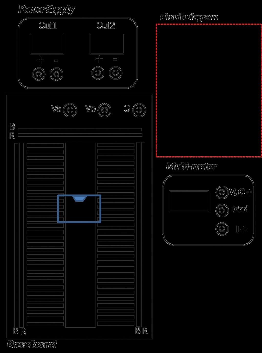
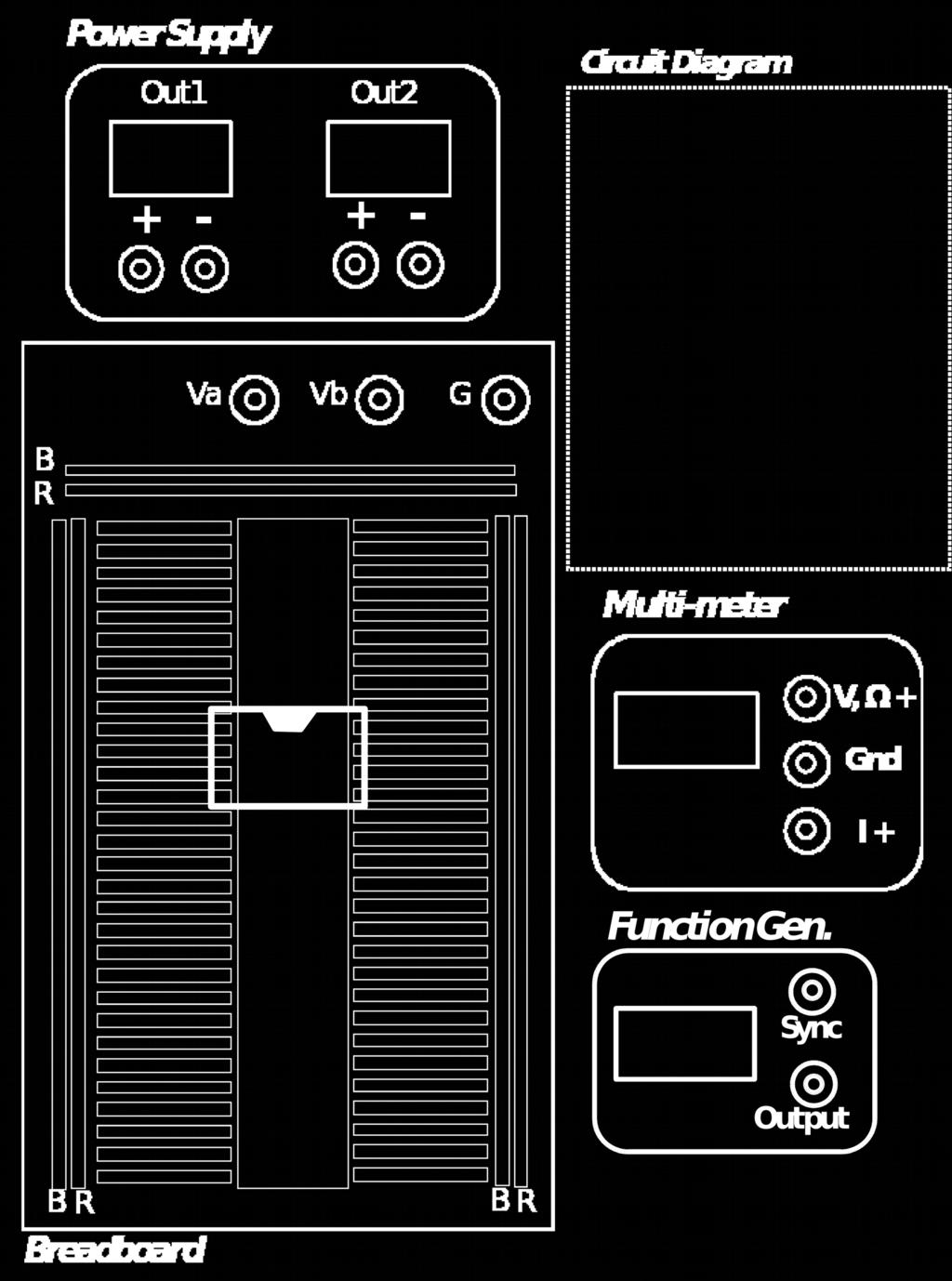
1 EECE Circuits and Signals: Biomedical Applications Lab 6 Sec 2 Getting started with Operational Amplifier Circuits DiMarzio Section Only: Prelab: 3 items in yellow. Reflection: Summary of what you learned, and answers to two questions in green. Part 1. Inverting Op-Amp Circuit Figure 1. Inverting op-amp circuit. Figure 2. DC power supply connections to op-amp. Common node is ground.
.")
2 Figure 3. The 741 Op-Amp DIP package, two diagrams (the different labeling of the pins indicates commonly used terminology and are used interchangeably, i.e. v n = inverting input, v p = non-inverting input, V+ = +Vcc, V- = -Vcc). 1.1 Draw a wiring diagram for the circuit diagram in Figure 1 on the attached protoboard diagram (with the power supply connections from Figure 2 and the signal connections from Figure 1!!). Note that: - The Op Amp DIP packaging will straddle two sets of horizontal rows. Note the position of the notch. The spec sheet is on Blackboard and will be used more extensively in the next lab. - The Op-Amp is an active component and requires +Vcc and Vcc power to pins 7 and 4, respectively; otherwise it will not work! It may take some thought and discussion with the instructor or TAs to understand how to set this up with the power supply! - You should use the long strips of your protoboard (buses) for the DC supply voltages. So use one for VCC, one for ground, and one for +VCC. Part 2. Building and Testing the Inverting Op-Amp Circuit 2.1 Build the Inverting Op-Amp circuit (Fig. 1 above) on your protoboard. Make V CC =10V and V CC = -10V. Note: Color code the supply voltage wires, and don t use those colors for other signals. You should use different colors for +10 V, -10 V, and Ground. We will be checking your circuits for good wiring practices. Two common wiring conventions are: 1) +Vcc = Red Ground = Black, -Vcc = Blue 2) +Vcc = Red Ground = Green -Vcc = Black (Pick either one you like but stick to it!) (The signal wires should be a fourth color.) 2.2. Choose your resistor values so that the circuit has a gain of G = V out / V in = -10. Use resistors > 1 kω for now.
3 2.3 Set the function generator to produce an input sine wave V input with 0.5 V amplitude (center to peak) and 1000 Hz frequency. (no DC offset) Remember that the function generator will produce center-to-peak amplitude of the set value, and not the peak-to-peak value. This is because every time you power on the signal generator, it gives the expected peak-to-peak value for a 50 Ohm load, and the load here is a much larger resistance. Your knowledge of Thevenin equivalents and voltage dividers should help you now to understand why it behaves differently with the larger load. You can change this setting from the default if you want, or just live with it being off by a factor of two (or in other words use the displayed value as the center-to-peak amplitude, ½ of the actual peak-to-peak value). 2.4 Using the oscilloscope, display the input and output signals of the amplifer at the same time. Measure the amplitudes of the input sine wave and the output sine wave. Q1: Based on these measurements, what is the gain of the system? Q2: Does it agree with your predicted value? 2.5 Q3: How can you verify that the gain is negative and not positive? 2.6 When you are convinced that the circuit is working as you intended, increase the amplitude of the sine wave input to 1.2V center-to-peak. Q4: Explain in your report what happened to the output, and why. Part 3. Summing Inverting Op-Amp Circuit 3.1 Suppose you had a basic function generator that could not produce a DC offset, but you wanted to add -1V DC to your output signal, v o. You could do this with a summing inverting amplifier, where v input and R i are your original AC input voltage and resistance from parts 1 and 2 and v 2 and R 2 are a DC source and an appropriate resistor to set the DC gain to obtain a total output of -1V+the original AC part.
4 Figure 4. Summing inverting amplifer. Gains for the two inputs are R f /R i and R f /R 2. The sum appears at the output. 3.2 Step 1: Figure out how to use the DC power supply to produce your -1V DC Offset. Note that you are obviously using the DC power supply to power the circuit, so your DC input must be either +10 or -10 V. However, you can use the 10V supply to produce a -1V DC output by choosing your R 2 value appropriately. Q5: How can you do this, in detail? 3.3 Step 2: Now modify your circuit from part 2 to add the -1V to the sinewave output. Set the function generator to produce an input sine wave V input with 0.5 V amplitude (center to peak) and 1000 Hz frequency (no DC offset). 3.4 Use the oscilloscope to check your result. Q6: Did you measure what you expect? Part 4 Instructions For the Lab Reflection The lab reflection for this lab is due as per the instructions on Blackboard. IMPORTANT: BEFORE YOU LEAVE THE LAB: (a) Turn off all of the equipment you have used on your workbench. (b) Make sure to have your notebook signed by an instructor or TA before you leave the lab. Department of Electrical Engineering, Northeastern University. Last updated: 10/1/16 D. Brooks, 9/28/16, N. McGruer; 8/10/15, M.Niedre.
5
EECE Circuits and Signals: Biomedical Applications. Lab 5. Thevenin Equivalents of Lab Equipment
 EECE 2150 - Circuits and Signals: Biomedical Applications Lab 5 Thevenin Equivalents of Lab Equipment DiMarzio Section Only: Prelab. Read the lab instructions carefully. (1) Draw a diagram in your notebook
Lab #6: Op Amps, Part 1
 Fall 2013 EELE 250 Circuits, Devices, and Motors Lab #6: Op Amps, Part 1 Scope: Study basic Op-Amp circuits: voltage follower/buffer and the inverting configuration. Home preparation: Review Hambley chapter
EECE Circuits and Signals: Biomedical Applications. Lab ECG I The Instrumentation Amplifier
 EECE 150 - Circuits and Signals: Biomedical Applications Lab ECG I The Instrumentation Amplifier Introduction: As discussed in class, instrumentation amplifiers are often used to reject common-mode signals
EECE Circuits and Signals: Biomedical Applications. Lab 3. Basic Instruments, Components and Circuits. Introduction to Spice and AC circuits
 EECE 2150 - Circuits and Signals: Biomedical Applications Lab 3 Basic Instruments, Components and Circuits. Introduction to Spice and AC circuits Introduction and Preamble: In this lab you will experiment
EE-3010 Lab # 5 Simulation of Operational Amplifier Circuits
 EE-3010 Lab # 5 Simulation of Operational Amplifier Circuits Objectives Investigation of amplifier circuits containing operational amplifiers. (Note: This is a two-part lab and may be done in two consecutive
Sirindhorn International Institute of Technology Thammasat University at Rangsit
 Sirindhorn International Institute of Technology Thammasat University at Rangsit School of Information, Computer and Communication Technology Practice Problems for the Final Examination COURSE : ECS204
Instructions for the final examination:
 School of Information, Computer and Communication Technology Sirindhorn International Institute of Technology Thammasat University Practice Problems for the Final Examination COURSE : ECS304 Basic Electrical
EE 210: CIRCUITS AND DEVICES
 EE 210: CIRCUITS AND DEVICES OPERATIONAL AMPLIFIERS PART II This is the second of two laboratory sessions that provide an introduction to the op amp. In this session you will study three amplifiers designs:
ECE Lab #4 OpAmp Circuits with Negative Feedback and Positive Feedback
 ECE 214 Lab #4 OpAmp Circuits with Negative Feedback and Positive Feedback 20 February 2018 Introduction: The TL082 Operational Amplifier (OpAmp) and the Texas Instruments Analog System Lab Kit Pro evaluation
BME 3512 Bioelectronics Laboratory Five - Operational Amplifiers
 BME 351 Bioelectronics Laboratory Five - Operational Amplifiers Learning Objectives: Be familiar with the operation of a basic op-amp circuit. Be familiar with the characteristics of both ideal and real
Data Conversion and Lab Lab 1 Fall Operational Amplifiers
 Operational Amplifiers Lab Report Objectives Materials See separate report form located on the course webpage. This form should be completed during the performance of this lab. 1) To construct and operate
University of North Carolina, Charlotte Department of Electrical and Computer Engineering ECGR 3157 EE Design II Fall 2009
 University of North Carolina, Charlotte Department of Electrical and Computer Engineering ECGR 3157 EE Design II Fall 2009 Lab 1 Power Amplifier Circuits Issued August 25, 2009 Due: September 11, 2009
INTRODUCTION. Figure 1 Three-terminal op amp symbol.
 Page 1/6 Revision 0 16-Jun-10 OBJECTIVES To reinforce the concepts behind operational amplifier analysis. Verification of operational amplifier theory and analysis. To successfully interpret and implement
ECE 220 Laboratory 3 Thevenin Equivalent Circuits, Constant Current Source, and Inverting Amplifier
 ECE 220 Laboratory 3 Thevenin Equivalent Circuits, Constant Current Source, and Inverting Amplifier Michael W. Marcellin The first portion of this document describes preparatory work to be completed in
Lab 10: Single Supply Amplifier
 Overview This lab assignment implements an inverting voltage amplifier circuit with a single power supply. The amplifier output contains a bias point which is removed by AC coupling the output signal.
When you have completed this exercise, you will be able to relate the gain and bandwidth of an op amp
 Op Amp Fundamentals When you have completed this exercise, you will be able to relate the gain and bandwidth of an op amp In general, the parameters are interactive. However, in this unit, circuit input
v 0 = A (v + - v - ) (1)
 (1)") UNIVERSITI TEKNOLOGI MALAYSIA KURSUS KEJURUTERAAN ELEKTRIK ELECTRONIC ENGINEERING LABORATORY 2 EXPERIMENT 2 : OPERATIONAL AMPLIFIER PRELIMINARY REPORT Name : Section : Group : Lecturer : Marks : 20 Attach
UNIVERSITI TEKNOLOGI MALAYSIA KURSUS KEJURUTERAAN ELEKTRIK ELECTRONIC ENGINEERING LABORATORY 2 EXPERIMENT 2 : OPERATIONAL AMPLIFIER PRELIMINARY REPORT Name : Section : Group : Lecturer : Marks : 20 Attach
Intro To Engineering II for ECE: Lab 7 The Op Amp Erin Webster and Dr. Jay Weitzen, c 2014 All rights reserved.
 Lab 7: The Op Amp Laboratory Objectives: 1) To introduce the operational amplifier or Op Amp 2) To learn the non-inverting mode 3) To learn the inverting mode 4) To learn the differential mode Before You
Electronics and Instrumentation Name ENGR-4220 Spring 1999 Section Experiment 4 Introduction to Operational Amplifiers
 Experiment 4 Introduction to Operational Amplifiers Purpose: Become sufficiently familiar with the operational amplifier (op-amp) to be able to use it with a bridge circuit output. We will need this capability
BME/ISE 3512 Bioelectronics. Laboratory Five - Operational Amplifiers
 BME/ISE 3512 Bioelectronics Laboratory Five - Operational Amplifiers Learning Objectives: Be familiar with the operation of a basic op-amp circuit. Be familiar with the characteristics of both ideal and
Lab: Operational Amplifiers
 Page 1 of 6 Laboratory Goals Familiarize students with Integrated Circuit (IC) construction on a breadboard Introduce the LM 741 Op-amp and its applications Design and construct an inverting amplifier
Introduction to the Op-Amp
 Purpose: ENGR 210/EEAP 240 Lab 5 Introduction to the Op-Amp To become familiar with the operational amplifier (OP AMP), and gain experience using this device in electric circuits. Equipment Required: HP
Lab 2 Operational Amplifier
 Lab 2 Operational Amplifier Last Name: First Name: Student Number: Lab Section: Monday Tuesday Wednesday Thursday Friday TA Signature: Note: The Pre-Lab section must be completed prior to the lab session.
University of Portland EE 271 Electrical Circuits Laboratory. Experiment: Op Amps
 University of Portland EE 271 Electrical Circuits Laboratory Experiment: Op Amps I. Objective The objective of this experiment is to learn how to use an op amp circuit to prevent loading and to amplify
Lab 6 Prelab Grading Sheet
 Lab 6 Prelab Grading Sheet NAME: Read through the Background section of this lab and print the prelab and in-lab grading sheets. Then complete the steps below and fill in the Prelab 6 Grading Sheet. You
ECE3204 D2015 Lab 1. See suggested breadboard configuration on following page!
 ECE3204 D2015 Lab 1 The Operational Amplifier: Inverting and Non-inverting Gain Configurations Gain-Bandwidth Product Relationship Frequency Response Limitation Transfer Function Measurement DC Errors
ECE ECE285. Electric Circuit Analysis I. Spring Nathalia Peixoto. Rev.2.0: Rev Electric Circuits I
 ECE285 Electric Circuit Analysis I Spring 2014 Nathalia Peixoto Rev.2.0: 140124. Rev 2.1. 140813 1 Lab reports Background: these 9 experiments are designed as simple building blocks (like Legos) and students
Operational Amplifiers: Part II
 1. Introduction Operational Amplifiers: Part II The name "operational amplifier" comes from this amplifier's ability to perform mathematical operations. Three good examples of this are the summing amplifier,
EECS40 Lab Introduction to Lab: Guide
 Aschenbach, Konrad Muthuswamy, Bharathwaj EECS40 Lab Introduction to Lab: Guide Objective The student will use the following circuit elements and laboratory equipment to make basic circuit measurements:
The Field Effect Transistor
 FET, OPAmps I. p. 1 Field Effect Transistors and Op Amps I The Field Effect Transistor This lab begins with some experiments on a junction field effect transistor (JFET), type 2N5458, and then continues
ECE159H1S University of Toronto 2014 EXPERIMENT #2 OP AMP CIRCUITS AND WAVEFORMS ECE159H1S
 ECE159H1S University of Toronto 2014 EXPERIMENT #2 OP AMP CIRCUITS AND WAVEFORMS ECE159H1S OBJECTIVES: To study the performance and limitations of basic op-amp circuits: the inverting and noninverting
Operational Amplifier Circuits
 ECE VIII. Basic 5 Operational Amplifier Circuits Lab 8 In this lab we will verify the operation of inverting and noninverting amplifiers constructed using Operational Amplifiers. We will also observe the
Prelab 10: Differential Amplifiers
 Name: Lab Section: Prelab 10: Differential Amplifiers For this lab, assume all NPN transistors are identical 2N3904 BJTs and all PNP transistors are identical 2N3906 BJTs. Component I S (A) V A (V) 2N3904
Operational Amplifiers
 Objective Operational Amplifiers Understand the basics and general concepts of operational amplifier (op amp) function. Build and observe output of a comparator and an amplifier (inverting amplifier).
An electronic unit that behaves like a voltagecontrolled
 1 An electronic unit that behaves like a voltagecontrolled voltage source. An active circuit element that amplifies, sums, subtracts, multiply, divide, differentiate or integrates a signal 2 A typical
University of Pennsylvania. Department of Electrical and Systems Engineering. ESE Undergraduate Laboratory. Analog to Digital Converter
 University of Pennsylvania Department of Electrical and Systems Engineering ESE Undergraduate Laboratory Analog to Digital Converter PURPOSE The purpose of this lab is to design and build a simple Digital-to-Analog
Physics 310 Lab 6 Op Amps
 Physics 310 Lab 6 Op Amps Equipment: Op-Amp, IC test clip, IC extractor, breadboard, silver mini-power supply, two function generators, oscilloscope, two 5.1 k s, 2.7 k, three 10 k s, 1 k, 100 k, LED,
EECS 100/43 Lab 6 Frequency Response
 Summer 7 Lab 6 EE/EE43. Objective EECS /43 Lab 6 Frequency Response In this lab, you will learn about the concept of gain-bandwidth product of an op-amp.. Equipment a. Breadboard b. Wire cutters c. Wires
University of Pittsburgh
 University of Pittsburgh Experiment #1 Lab Report Frequency Response of Operational Amplifiers Submission Date: 05/29/2018 Instructors: Dr. Ahmed Dallal Shangqian Gao Submitted By: Nick Haver & Alex Williams
Lab 1: Non-Ideal Operational Amplifier and Op-Amp Circuits
 Lab 1: Non-Ideal Operational Amplifier and Op-Amp Circuits 1. Learning Outcomes In this lab, the students evaluate characteristics of the non-ideal operational amplifiers. Students use a simulation tool
ES250: Electrical Science. HW6: The Operational Amplifier
 ES250: Electrical Science HW6: The Operational Amplifier Introduction This chapter introduces the operational amplifier or op amp We will learn how to analyze and design circuits that contain op amps,
EE 3305 Lab I Revised July 18, 2003
 Operational Amplifiers Operational amplifiers are high-gain amplifiers with a similar general description typified by the most famous example, the LM741. The LM741 is used for many amplifier varieties
The Operational Amplifier This lab is adapted from the Kwantlen Lab Manual
 Name: Partner(s): Desk #: Date: Purpose The Operational Amplifier This lab is adapted from the Kwantlen Lab Manual The purpose of this lab is to examine the functions of operational amplifiers (op amps)
Electronics EECE2412 Spring 2016 Exam #1
 Electronics EECE2412 Spring 2016 Exam #1 Prof. Charles A. DiMarzio Department of Electrical and Computer Engineering Northeastern University 18 February 2016 File:12140/exams/exam1 Name: : Row # : Seat
CENG4480 Embedded System Development and Applications The Chinese University of Hong Kong Laboratory 1: Op Amp (I)
") CENG4480 Embedded System Development and Applications The Chinese University of Hong Kong Laboratory 1: Op Amp (I) Student ID: 2018 Fall 1 Introduction This lab session introduces some very basic concepts
CENG4480 Embedded System Development and Applications The Chinese University of Hong Kong Laboratory 1: Op Amp (I) Student ID: 2018 Fall 1 Introduction This lab session introduces some very basic concepts
EE431 Lab 1 Operational Amplifiers
 Feb. 10, 2015 Report all measured data and show all calculations Introduction The purpose of this laboratory exercise is for the student to gain experience with measuring and observing the effects of common
Experiment 8 Frequency Response
 Experiment 8 Frequency Response W.T. Yeung, R.A. Cortina, and R.T. Howe UC Berkeley EE 105 Spring 2005 1.0 Objective This lab will introduce the student to frequency response of circuits. The student will
Lab 2: Common Emitter Design: Part 2
 Lab 2: Common Emitter Design: Part 2 ELE 344 University of Rhode Island, Kingston, RI 02881-0805, U.S.A. 1 Linearity in High Gain Amplifiers The common emitter amplifier, shown in figure 1, will provide
EGR Laboratory 3 - Operational Amplifiers (Op Amps)
") EGR 215 - Laboratory 3 - Operational Amplifiers (Op Amps) Authors C. Ramon, R.D. Christie, K.F. Böhringer of the University of Washington Objectives At the end of this lab, you will be able to: Construct
EGR 215 - Laboratory 3 - Operational Amplifiers (Op Amps) Authors C. Ramon, R.D. Christie, K.F. Böhringer of the University of Washington Objectives At the end of this lab, you will be able to: Construct
Massachusetts Institute of Technology Department of Electrical Engineering and Computer Science Circuits & Electronics Spring 2005
 Massachusetts Institute of Technology Department of Electrical Engineering and Computer Science 6.002 Circuits & Electronics Spring 2005 Lab #2: MOSFET Inverting Amplifiers & FirstOrder Circuits Introduction
Lab 6: Instrumentation Amplifier
 Lab 6: Instrumentation Amplifier INTRODUCTION: A fundamental building block for electrical measurements of biological signals is an instrumentation amplifier. In this lab, you will explore the operation
EK307 Passive Filters and Steady State Frequency Response
 EK307 Passive Filters and Steady State Frequency Response Laboratory Goal: To explore the properties of passive signal-processing filters Learning Objectives: Passive filters, Frequency domain, Bode plots
Equipment: You will use the bench power supply, function generator and oscilloscope.
 EE203 Lab #0 Laboratory Equipment and Measurement Techniques Purpose Your objective in this lab is to gain familiarity with the properties and effective use of the lab power supply, function generator
EE 233 Circuit Theory Lab 3: First-Order Filters
 EE 233 Circuit Theory Lab 3: First-Order Filters Table of Contents 1 Introduction... 1 2 Precautions... 1 3 Prelab Exercises... 2 3.1 Inverting Amplifier... 3 3.2 Non-Inverting Amplifier... 4 3.3 Integrating
California University of Pennsylvania. Department of Applied Engineering & Technology. Electrical / Computer Engineering Technology
 California University of Pennsylvania Department of Applied Engineering & Technology Electrical / Computer Engineering Technology EET 215: Introduction to Instrumentations Lab No.5b Operational Amplifier
Integrators, differentiators, and simple filters
 BEE 233 Laboratory-4 Integrators, differentiators, and simple filters 1. Objectives Analyze and measure characteristics of circuits built with opamps. Design and test circuits with opamps. Plot gain vs.
Chapter 3: Operational Amplifiers
 Chapter 3: Operational Amplifiers 1 OPERATIONAL AMPLIFIERS Having learned the basic laws and theorems for circuit analysis, we are now ready to study an active circuit element of paramount importance:
ECEN Network Analysis Section 3. Laboratory Manual
 ECEN 3714----Network Analysis Section 3 Laboratory Manual LAB 07: Active Low Pass Filter Oklahoma State University School of Electrical and Computer Engineering. Section 3 Laboratory manual - 1 - Spring
EE 210 Lab Exercise #5: OP-AMPS I
 EE 210 Lab Exercise #5: OP-AMPS I ITEMS REQUIRED EE210 crate, DMM, EE210 parts kit, T-connector, 50Ω terminator, Breadboard Lab report due at the ASSIGNMENT beginning of the next lab period Data and results
TECH 3232 Fall 2010 Lab #1 Into To Digital Circuits. To review basic logic gates and digital logic circuit construction and testing.
 TECH 3232 Fall 2010 Lab #1 Into To Digital Circuits Name: Purpose: To review basic logic gates and digital logic circuit construction and testing. Introduction: The most common way to connect circuits
Electronic Simulation Software for Teaching and Learning
 Electronic Simulation Software for Teaching and Learning Electronic Simulation Software: 1. Ohms Law (a) Example 1 Zoom 200% (i) Run the simulation to verify the calculations provided. (ii) Stop the simulation
Audio Amplifier. November 27, 2017
 Audio Amplifier November 27, 2017 1 Pre-lab No pre-lab calculations. 2 Introduction In this lab, you will build an audio power amplifier capable of driving a 8 Ω speaker the way it was meant to be driven...
Welcome to your second Electronics Laboratory Session. In this session you will learn about how to use resistors, capacitors and inductors to make
 Welcome to your second Electronics Laboratory Session. In this session you will learn about how to use resistors, capacitors and inductors to make simple circuits. You will find out how these circuits
Laboratory 8 Lock-in amplifier 1
 Laboratory 8 Lock-in amplifier 1 Prior to the lab, Understand the circuit (Figure 1). Download from the blog and read the spec sheets for the comparator and the quadrant multiplier. Draw how to connect
Lab 4: Analysis of the Stereo Amplifier
 ECE 212 Spring 2010 Circuit Analysis II Names: Lab 4: Analysis of the Stereo Amplifier Objectives In this lab exercise you will use the power supply to power the stereo amplifier built in the previous
Dev Bhoomi Institute Of Technology Department of Electronics and Communication Engineering PRACTICAL INSTRUCTION SHEET REV. NO. : REV.
 Dev Bhoomi Institute Of Technology Department of Electronics and Communication Engineering PRACTICAL INSTRUCTION SHEET LABORATORY MANUAL EXPERIMENT NO. ISSUE NO. : ISSUE DATE: July 200 REV. NO. : REV.
How to Wire an Inverting Amplifier Circuit
 How to Wire an Inverting Amplifier Circuit Figure 1: Inverting Amplifier Schematic Introduction The purpose of this instruction set is to provide you with the ability to wire a simple inverting amplifier
EXPERIMENT 3 Circuit Construction and Operational Amplifier Circuits
 ELEC 2010 Lab Manual Experiment 3 PRE-LAB Page 1 of 8 EXPERIMENT 3 Circuit Construction and Operational Amplifier Circuits Introduction In this experiment you will learn how to build your own circuits
Lab 1: Non-Ideal Operational Amplifier and Op-Amp Circuits
 Lab 1: Non-Ideal Operational Amplifier and Op-Amp Circuits 1. Learning Outcomes In this lab, the students evaluate characteristics of the non-ideal operational amplifiers. Students use a simulation tool
OPERATIONAL AMPLIFIERS LAB
 1 of 6 BEFORE YOU BEGIN PREREQUISITE LABS OPERATIONAL AMPLIFIERS LAB Introduction to Matlab Introduction to Arbitrary/Function Generator Resistive Circuits EXPECTED KNOWLEDGE Students should be familiar
Physics 364, Fall 2014, Lab #7 (opamps I) Monday, September 22 (section 401); Tuesday, September 23 (section 402)
 Monday, September 22 (section 401); Tuesday, September 23 (section 402)") Physics 364, Fall 2014, Lab #7 Name: (opamps I) Monday, September 22 (section 401); Tuesday, September 23 (section 402) Course materials and schedule are at positron.hep.upenn.edu/p364 We will spend the
Physics 364, Fall 2014, Lab #7 Name: (opamps I) Monday, September 22 (section 401); Tuesday, September 23 (section 402) Course materials and schedule are at positron.hep.upenn.edu/p364 We will spend the
Lab 9: Operational amplifiers II (version 1.5)
") Lab 9: Operational amplifiers II (version 1.5) WARNING: Use electrical test equipment with care! Always double-check connections before applying power. Look for short circuits, which can quickly destroy
Lab 9: Operational amplifiers II (version 1.5) WARNING: Use electrical test equipment with care! Always double-check connections before applying power. Look for short circuits, which can quickly destroy
ECE4902 C Lab 5 MOSFET Common Source Amplifier with Active Load Bandwidth of MOSFET Common Source Amplifier: Resistive Load / Active Load
 ECE4902 C2012 - Lab 5 MOSFET Common Source Amplifier with Active Load Bandwidth of MOSFET Common Source Amplifier: Resistive Load / Active Load PURPOSE: The primary purpose of this lab is to measure the
INDIANA UNIVERSITY, DEPT. OF PHYSICS, P400/540 LABORATORY FALL Laboratory #6: Operational Amplifiers
 INDIANA UNIVERSITY, DEPT. OF PHYSICS, P400/540 LABORATORY FALL 008 Laboratory #: Operational Amplifiers Goal: Study the use of the operational amplifier in a number of different configurations: inverting
University of Portland EE 271 Electrical Circuits Laboratory. Experiment: Inductors
 University of Portland EE 271 Electrical Circuits Laboratory Experiment: Inductors I. Objective The objective of this experiment is to verify the relationship between voltage and current in an inductor,
Digital Applications of the Operational Amplifier
 Lab Procedure 1. Objective This project will show the versatile operation of an operational amplifier in a voltage comparator (Schmitt Trigger) circuit and a sample and hold circuit. 2. Components Qty
Department of Mechanical Engineering
 Department of Mechanical Engineering 2.010 CONTROL SYSTEMS PRINCIPLES Introduction to the Operational Amplifier The integrated-circuit operational-amplifier is the fundamental building block for many electronic
Lab 4. Transistor as an amplifier, part 2
 Lab 4 Transistor as an amplifier, part 2 INTRODUCTION We continue the bi-polar transistor experiments begun in the preceding experiment. In the common emitter amplifier experiment, you will learn techniques
A Practical Exercise Name: Section:
 AC Thèvenin Updated 17 AUG 2016 A Practical Exercise Name: Section: I. Purpose. 1. Review the construction and analysis of AC circuits using a DMM and/or oscilloscope. 2. Introduce the AC Thèvenin equivalent
Lab 2: Discrete BJT Op-Amps (Part I)
") Lab 2: Discrete BJT Op-Amps (Part I) This is a three-week laboratory. You are required to write only one lab report for all parts of this experiment. 1.0. INTRODUCTION In this lab, we will introduce and
Lab 2: Discrete BJT Op-Amps (Part I) This is a three-week laboratory. You are required to write only one lab report for all parts of this experiment. 1.0. INTRODUCTION In this lab, we will introduce and
Laboratory 8 Operational Amplifiers and Analog Computers
 Laboratory 8 Operational Amplifiers and Analog Computers Introduction Laboratory 8 page 1 of 6 Parts List LM324 dual op amp Various resistors and caps Pushbutton switch (SPST, NO) In this lab, you will
Lab Exercise # 9 Operational Amplifier Circuits
 Objectives: THEORY Lab Exercise # 9 Operational Amplifier Circuits 1. To understand how to use multiple power supplies in a circuit. 2. To understand the distinction between signals and power. 3. To understand
Function Generator Op-amp Summing Circuits Pulse Width Modulation LM311 Comparator
 Function Generator Op-amp Summing Circuits Pulse Width Modulation LM311 Comparator Objective ECE3204 D2015 Lab 3 The main purpose of this lab is to gain familiarity with use of the op-amp in a non-linear
Fill in the following worksheet-style pages. A colored pen or pencil works best. The procedure is:
 14: ALIASING I. PRELAB FOR ALIASING LAB You might expect that to record a frequency of 4000 Hz you would have to sample at a rate of at least 4000 Hz. It turns out, however, that you actually have to sample
I1 19u 5V R11 1MEG IDC Q7 Q2N3904 Q2N3904. Figure 3.1 A scaled down 741 op amp used in this lab
 Lab 3: 74 Op amp Purpose: The purpose of this laboratory is to become familiar with a two stage operational amplifier (op amp). Students will analyze the circuit manually and compare the results with SPICE.
DEPARTMENT OF ELECTRICAL ENGINEERING LAB WORK EE301 ELECTRONIC CIRCUITS
 DEPARTMENT OF ELECTRICAL ENGINEERING LAB WORK EE301 ELECTRONIC CIRCUITS EXPERIMENT : 5 TITLE : ACTIVE FILTERS OUTCOME : Upon completion of this unit, the student should be able to: 1. gain experience with
Phy 335, Unit 4 Transistors and transistor circuits (part one)
") Mini-lecture topics (multiple lectures): Phy 335, Unit 4 Transistors and transistor circuits (part one) p-n junctions re-visited How does a bipolar transistor works; analogy with a valve Basic circuit
Mini-lecture topics (multiple lectures): Phy 335, Unit 4 Transistors and transistor circuits (part one) p-n junctions re-visited How does a bipolar transistor works; analogy with a valve Basic circuit
Amplification. Objective. Equipment List. Introduction. The objective of this lab is to demonstrate the basic characteristics an Op amplifier.
 Amplification Objective The objective of this lab is to demonstrate the basic characteristics an Op amplifier. Equipment List Introduction Computer running Windows (NI ELVIS installed) National Instruments
Designing Information Devices and Systems I Discussion 10A
 Last Updated: 2019-04-09 07:42 1 EECS 16A Spring 2019 Designing Information Devices and Systems I Discussion 10A For Reference: Circuits Cookbook, Abridged Voltage Divider Voltage Summer Unity Gain Buffer
University of Pennsylvania Department of Electrical and Systems Engineering. ESE 206: Electrical Circuits and Systems II - Lab
 University of Pennsylvania Department of Electrical and Systems Engineering ESE 206: Electrical Circuits and Systems II - Lab AC POWER ANALYSIS AND DESIGN I. Purpose and Equipment: Provide experimental
Field Effect Transistors
 Field Effect Transistors Purpose In this experiment we introduce field effect transistors (FETs). We will measure the output characteristics of a FET, and then construct a common-source amplifier stage,
Lab 4 - Operational Amplifiers 1 Gain ReadMeFirst
 Lab 4 - Operational Amplifiers 1 Gain ReadMeFirst Lab Summary There are three basic configurations for operational amplifiers. If the amplifier is multiplying the amplitude of the signal, the multiplication
Class #7: Experiment L & C Circuits: Filters and Energy Revisited
 Class #7: Experiment L & C Circuits: Filters and Energy Revisited In this experiment you will revisit the voltage oscillations of a simple LC circuit. Then you will address circuits made by combining resistors
Experiment #8: Designing and Measuring a Common-Collector Amplifier
 SCHOOL OF ENGINEERING AND APPLIED SCIENCE DEPARTMENT OF ELECTRICAL AND COMPUTER ENGINEERING ECE 2115: ENGINEERING ELECTRONICS LABORATORY Experiment #8: Designing and Measuring a Common-Collector Amplifier
Michael Tang TA: Ketobi 7/18/13
 Michael Tang TA: Ketobi 7/18/13 Lab Station #5 Section 1 Partners: Matt, Ryan Task 1: Basic Inverting Amplifier For this task, a basic inverting amplifier was needed to be designed to amplify the output
Physics 323. Experiment # 1 - Oscilloscope and Breadboard
 Physics 323 Experiment # 1 - Oscilloscope and Breadboard Introduction In order to familiarise yourself with the laboratory equipment, a few simple experiments are to be performed. References: XYZ s of
Lab 10: Oscillators (version 1.1)
") Lab 10: Oscillators (version 1.1) WARNING: Use electrical test equipment with care! Always double-check connections before applying power. Look for short circuits, which can quickly destroy expensive equipment.
Lab 10: Oscillators (version 1.1) WARNING: Use electrical test equipment with care! Always double-check connections before applying power. Look for short circuits, which can quickly destroy expensive equipment.
EK307 Active Filters and Steady State Frequency Response
 EK307 Active Filters and Steady State Frequency Response Laboratory Goal: To explore the properties of active signal-processing filters Learning Objectives: Active Filters, Op-Amp Filters, Bode plots Suggested
Module 0: Introduction to Electronics
 Module 0: Introduction to Electronics Contents 1 Objectives and Learning Goals 1 2 Roadmap and Milestones 2 3 Lab Procedures 2 3.1 DC measurements..................................... 2 3.2 Impedance and
ESE 150 Lab 04: The Discrete Fourier Transform (DFT)
") LAB 04 In this lab we will do the following: 1. Use Matlab to perform the Fourier Transform on sampled data in the time domain, converting it to the frequency domain 2. Add two sinewaves together of differing
LAB 04 In this lab we will do the following: 1. Use Matlab to perform the Fourier Transform on sampled data in the time domain, converting it to the frequency domain 2. Add two sinewaves together of differing