Smart Room Attendance Monitoring and Location Tracking with ibeacon Technology
|
|
|
- Teresa Welch
- 5 years ago
- Views:
Transcription
1 Smart Room Attendance Monitoring and Location Tracking with ibeacon Technology A Major Qualifying Project Submitted to the Faculty of WORCESTER POLYTECHNIC INSTITUTE in partial fulfillment of the requirements for the Degree of Bachelor of Science in Electrical and Computer Engineering By Savannah Redetzke, Andrew Vanner, and Raymond Otieno Advisor: Professor Kaveh Pahlavan Co-Advisor: Professor Jahangir Rahman This report represents work of WPI undergraduate students submitted to the faculty as evidence of a degree requirement. WPI routinely publishes these reports on its web site without editorial or peer review. For more information about the projects program at WPI, see htttp:// *This project was sponsored by Worcester Polytechnic Institute, Electrical and Computer Engineering Department as a Major Qualifying Project (MQP) for senior undergraduate studies.
2 Abstract The objective of this project was to develop a system and a phone application using ibeacon technology to track people s attendance and location at different types of events. This includes tracking their location by using a location algorithm and receiving identifying information from each person through the use of a phone application. This information will then be sent to a server for record keeping. The project began with extensive data collection to determine the capabilities of the ibeacon technology. We collected RSSI data based on different transmission powers and determined the correct number, placement and the transmission power to ensure complete coverage. Location data was collected using both the ibeacon & Eddystone Scanner phone application developed by Flurp Laboratories and the Least Mean Squared Algorithm. The location results for both of these was compared for accuracy using Cramer-Rao. The next part of the project depended upon the creation of a phone application that was capable of detecting the signals from the ibeacon, collected data from the user of the application and sending this information to a server. To accomplish this, the phone application was developed for an Android Phone with Bluetooth Low Energy Capabilities. The application allows users to enter a username and password and includes the ability to terminate the monitoring capabilities of the application. The data collected by the phone application is sent to a text file stored within the offsite server Dropbox. This text file is accessed by an Excel worksheet which imports the data and quantifies it for data representation and analysis. 2
3 Acknowledgements The group would like to thank a few individuals and organizations for assisting us throughout this project. Professor Kaveh Pahlavan is our main advisor who helped us in coming up with ideas for this project and guided us through the entire process. He is joined by Professor Jahangir Rahman who provided us with valuable feedback on our progress, reports, and presentations. We would also like to thank Julang Ying, a WPI graduate student, for assisting us with location algorithm testing and analysis. Finally, we would like to thank WPI and the Electrical and Computer Engineering department for providing us with the funding, locations, and resources needed to complete this project. Without all of these supporting people, this project would not be possible. 3
4 Table of Contents 1.0 Introduction Motivation Project Description Report Outline Background in Localization Using ibeacon Bluetooth Low Energy ibeacon Estimote Beacons Performance of Location Algorithms Design and Performance Evaluation Methodology ibeacon Coverage Design Goal Smartphone Application Design of Algorithms Centroid Algorithm Trilateration Performance Evaluation with Creamer Rao Lower Bound Cramer Rao Lower Bound for Ranging Cramer Rao Lower Bound for Localization Server and User Interface Results and Discussion Algorithm Evaluations Smartphone Application Results Server Interface Results Conclusions and Future Work...45 References...46 Appendix A: Code for Beacon Placement in Room AK Appendix B: Code for Graphic Interface Excel Sheet...56 Appendix C: Raw Data Collection for Measuring RSSI in Room Appendix D: Conference Paper for ISENG
5 Table of Figures Figure 1.1 Project General Architecture... 8 Figure 2.1: Frequency Organization Diagram Figure 2.2: Two ibeacons developed by Estimote Figure 2.3: Advertisement of UUID, Major, and Minor by 3 different Estimote devices Figure 2.4: Localization Algorithms Summary Figure 3.1: Initial Consideration for ibeacon Placement in Atwater Kent Room Figure 3.2: Path-Loss Color Gradient Graphic of Atwater Kent Room Figure 3.3: RSSI Color Gradient Graphic of Atwater Kent Room Figure 3.4: Interaction with Identifiable Beacons Figure 3.5 Estimote Beacon Producing Light Figure 3.6: Reconfiguration of Beacons Figure 3.7: Ideal Trilateration for 3 Transmitters (ibeacons) Figure 4.1: Coverage Probabilities Matlab Contour Simulation Figure 4.2: Centroid Algorithm Showing the Intersections Figure 4.3: Centroid Algorithm Matlab Localization Results Figure 4.4: Simulation of Trilateration for Location Figure 4.5: Simulation of trilateration for Location Figure 4.6: Results for LMS Algorithm Figure 4.7: Matlab Contour Simulation for the 4 ibeacons Figure 4.8: Matlab Contour Simulation for the 5 ibeacons Figure 4.9: Cumulative Probability of Distance Measurement Error Figure 4.10: Developed Smartphone Application Screen Figure 4.11: Developed Smartphone Application Message Figure 4.12: Text File for Phone Import Figure 4.13: Raw Data Imported with Command Button Program Figure 4.14: Pivot Table Displaying Attendance for snredetzke Figure 4.15: Pivot Table for Displaying Dates User snredetzke Attended Class Figure 4.16: Bar Graph Displaying Class Attendance of snredetzke Figure 4.17: Slicer Diagram of Data Imported into Excel Program Figure 4.18: Slicer Diagram of Data Pertaining to Room Figure 4.19: Slicer Diagram of Data Pertaining to Room 233 and Class CS
6 Table of Equations Equation Equation Equation Equation Equation Equation Equation Equation Equation Equation Equation Equation Equation
7 1.0 Introduction This project began with identifying an issue which effects people in day to day life, and how we could design a system to alleviate the problem. The issue we identified was the difficulties associated with attendance monitoring and indoor localization. Once we determined the issue, our next step was to design an overall system architecture to enable us to focus our efforts on each component in turn. The introduction of our paper serves to detail both our motivation and our overall approach to solving the problem. 1.1 Motivation The motivation for this project came from the difficulty of recording the number of people at any type of event or class. At WPI, the traditional ways to monitor who attends an event are to swipe your WPI Student Identification (ID) Card on a card reader, physically sign in on a piece of paper, or use a device called clickers that connect to the classroom computer. However, each of these traditional ways have drawbacks that would be solved with our project s design. The first option is swiping your WPI Student ID Card which monitors your attendance by recording an identification number that is unique to you from the card. However, it is time consuming, laborious and prone to missing people who attend an event but do not swipe their ID card. The second: physically signing in on a piece of paper is equally laborious, prone to human error and if you wished to track who went to the class or event you have to enter the information onto a computer manually. The third, the clicker is designed for students to answer in class questions displayed on the projector. Their attendance is monitored based on who answered the questions. However, the students who forget their clicker cannot answer the questions, therefore losing class participation points in addition to losing credit for even attending the class. Most students, however, will always remember to have a phone in their pocket or purse reducing 7
8 the chances of a student missing out on potential class participation grade due to a failure of attendance taking. In addition, students and faculty will not have to stand in line to swipe their IDs, or pass around a piece of paper. This will not only save time to be used in more productive ways but will also increase the efficiency of the system while reducing the amount of human error. 1.2 Project Description This project was organized into four main sections. These sections were: to monitor when multiple people enter a room, to transit identifying information about each person when in room, to identify the location of each person within the room and to record and organize information for each person to track attendance and location. To complete each section of the project, we designed the basic design architecture as shown below in Figure 1.1. The design architecture is broken down into four basic components. Number one represents the multiple ibeacons required for both determining location and identifying when a person enters a room. Number two represents the smartphone that using the application that this project will design will detect the ibeacons, utilize a location algorithm to determine where in the room it is, and submit identifying information to number three, the server, at regular intervals. The server stores this information to be accessed by number four, the computer graphic interface, which is used to identify, track and record a person s username, date that they are in the room, time they are in the room, the room they are in (designated by a number) and the location in the room. 8
9 Figure 1.1: Project General Architecture Overview to Demonstrate the Block Diagram of the Project and the Lines of Communication between Different Technologies Included in the Project 1.3 Report Outline This report covers the background technology that makes this project work, the methodology used in this project to achieve the desired goals, the results of the project, and a conclusion that provides ideas for future work. The Background in Localization Using ibeacon(section 2.0) serves as an introduction to Bluetooth Low Energy as well as the ibeacon implementation of this technology. There is an explanation of Estimote Location Beacons for those that are unfamiliar with the devices. It also covers different types of location algorithms considered for this project. The Design and Performance Evaluation Methodology (Section 3.0) covers the various components of the project such as algorithm accuracy and optimization, smartphone application development, server interface development, and physical beacon deployment strategies. The Results and Discussion (Section 4.0) contains the results of this project to see how testing compares to theory and how the project s goals are actualized. We compare the accuracy of the algorithm implemented compared to other methods as well as the Cramer Rao Lower Bound (CRLB). This shows 9
10 how the phone application will look for users as well as how the graphic user interface works for administrators. Finally, the Conclusion (Section 5.0) summarizes the project as a whole. In addition, we speculate on the ways this system can be used in the professional world and what changes would need to be made before this can happen. In addition to this report we have included four appendixes. Appendix A is a compilation of the code used in Matlab to determine Beacon Placement calculations. Appendix B contains the Visual Basic code used in creating the user interface. Appendix C includes all the data collected during the project, such as RSSI, distance measurements and calculated path-loss. Appendix D contains a copy of a paper that we submitted to the 2017 International Systems Engineering Conference. 10
11 2.0 Background in Localization Using ibeacon This project contains four main technologies, that when utilized together made this project possible. These technologies are: Bluetooth Low Energy (BLE), ibeacon, Estimote Beacons and Location Algorithms. BLE is a wireless network connection which is used to exchange tiny and static radio signals within short distances. It has a low power consumption which makes ideal to be used in this project because it is easy to power and does not contribute to being an obtrusive addition to any designated space. BLE is contained within our second technology, ibeacon which was designed to provide indoor geolocation by transmitting signals and allowing applications to receive the signals and information. This technology is also contained within the Estimote Beacon. It allows this project to determine RSSI values, the distance you can be from an Estimote Beacon and add information to each Estimote Beacon for it to transmit to any application with Bluetooth 4.0 or above [2]. The last section of technology that this project uses are location algorithms. These algorithms are lines of code which can use RSSI measurements and multiple Estimote Beacons to determine the exact location of someone in a designated space. Channel, or path-loss modelling was used to determine best setup for the access points and Cramer Rao Lower Bound was used to evaluate algorithm with the least variance of estimator location error [1]. 2.1 Bluetooth Low Energy Bluetooth Low Energy (BLE) is a wireless network connection used to exchange tiny and static radio signals within short distances, approximately 200 m or less depending on the device. It was introduced about half a decade ago as Bluetooth 4.0 to the M2M communication and internet of things (IOT) world although it was originally invented by Nokia in 2006 under the name Wibree. BLE was known by its commercial name Bluetooth Smart after being transferred to Bluetooth Special Interest Group (BSIG). What makes this technology unique, is the Low Energy in the name. BLE has a very 11

12 low power consumption as compared to regular Bluetooth (802.15). Based on usage and settings, BLE can last up to 3 years or more on a single battery. The other features of BLE include using a 4 byte ARM cortex CPU embedded with accelerometer for motion detection, temperature sensor, and operates within MHz on an unlicensed frequency band. It uses 3/40 available channels for advertising it s position. The three channels are 37 (2402 MHz), 38 (2426 MHz), and 39 (2480 MHz) as shown on Figure Broadcasting rate and width for each channel is 50 Hz and 2 MHz respectively. Figure 2.1 shows how the channels are organized within BLE. The transmission power ranges from 0 to -40dBM. The remaining channels are used for receiving the signals. BLE uses Gaussian Frequency Shift Keying Modulation and Frequency Hopping Spread Spectrum with a connection time of 6ms, 3 byte Cyclic Redundancy Check, a 4 byte integrity check, and a 16 byte Advanced Encryption Standard security. Figure 2.1: Frequency Organization Diagram of the Forty Channels used by BLE for Three of its Uses: Advertisement, Receiver and WiFi Lineup (Source argenox.com) 2.2 ibeacon ibeacon is Apple s version of BLE created to provide indoor geolocation and to introduce it to 12

13 the public via Apple s ios platform. It permits applications to listen and search for advertised radio signals. The technology is compatible with any blue tooth device with version 4.0 and above. ibeacon is used in ranging and region monitoring. The transmitter, also known as the broadcaster announces its location by sending a packet that contains Universal Unique Identifier (UUID), Major, Minor, and transmit (Tx) power. It operates in a similar way to a lighthouse, broadcasting its position and IDs however it does not receive signals. 2.3 Estimote Beacons The hardware that uses both ibeacon technology and BLE that is utilized within this project is known as Estimote Beacons. These beacons are developed by Estimote Inc. and are about the size of a child s fist. Two Estimote Location Beacons are pictured below in Figure 2.2. All Estimote devices have a default UUID of B9407F30-F5F8-466E-AFF B57FE6D. UUID is a 256 (128 bits) nibble string for differentiating a large group of beacons that are related. It follows an digit format. Figure 2.2: Two ibeacons developed by Estimote utilizing BLE Technology to Transmit Information that can be Detected by BLE Compatible Devices The Major is a 32 nibble string that is a subset of UUID. Minor is similar to Major in size except that it identifies the exact beacons. The last part of the packet is transmission power that is responsible for identifying the distance from the transmitting beacon which is measured in terms of a meter from the beacon. The Figure 2.3 below is a screenshot taken to show an ios ibeacon application receives signals 13
14 from broadcasters. Figure 2.3: Advertisement of UUID, Major, and Minor by 3 different ibeacon devices using the Phone Application Estimote developed by Estimote 2.4 Performance of Location Algorithms There are numerous localization algorithms that are available for use with different error ranges and accuracies. Some examples of the algorithms are fingerprinting, trilateration, triangulation, Pedestrian Dead Reckoning (PDR), proximity, and hybrid methods [35]. These location algorithms will be compared to a mathematical limit called Cramer Rao Lower Bound (CRLB). CRLB is a mathematical lower bound that represents the best accuracy for a location estimator. The closer these algorithms fall to it, the more accurate they are. Fingerprinting uses the nearest node to estimate a distance/location with the help of access points and their corresponding RSS values[35]. The nearest node is determined by an access point with the highest RSS value. Whereas Triangulation uses three or more triangles intersections to estimate the 14
15 location and distance of a receiving node. It mostly focuses on the angle and one know/measured distance of the triangles being used and the other two sides determined based on the data. Trilateration is similar to triangulation but it uses spheres to determine the distance/ location in 3D and circles in 1 and 2D configurations. This project is based on a 2D configuration. A summary of how various localization algorithms compare with each other is depicted in Figure 2.4. These are just a few of the many available algorithms. Some of the abbreviations on the figure are Angle of Arrival (AoA), Distance of Arrival (DoA), and Received Signal Strength (RSS). Figure 2.4: Localization Algorithms Summary Comparison Based on Various Measurement Techniques [35] 15
16 3.0 Design and Performance Evaluation Methodology To successfully develop this product it is divided into four separate parts. Each part serves to monitor when multiple people enter a room, transit identifying information about each person when in room, identify the location of each person within the room, and record this information for each person. The four main sections are: Location Algorithms, ibeacon Coverage Design, Server and User Interface, and Smart Phone Application. The first part of this project, monitoring when multiple people enter the room, falls into the section of ibeacon Coverage Design. ibeacon Coverage Design is focused on determining the range of each of the ibeacons, as well as their placement so they can transmit over an entire designated space. The second part of this project, transiting identifying information about each person in the room, falls under the purview of the Smartphone Application. This section concentrates on working with the Android operating system, Dropbox Server and the Estimote ibeacon Application Program Interface (API) to both enable the application user to submit their information and send it to the Dropbox Server for data collection and processing. The third part of this project, identify the location of each person uses the section, is Location Algorithms. The location algorithms section concentrates on determining a feasible location algorithm using RSSI values, determining its accuracy compared to other location algorithms and implementing the chosen algorithm into the Phone Application. The last part of this project, recording the information sent by the Application for each person falls into the Server and User Interface task. This task is focused on developing an Excel program on a Dropbox server which imports the data deposited by the phone into a text file, and organizes the information to a user friendly display. 16
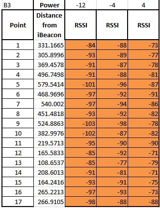
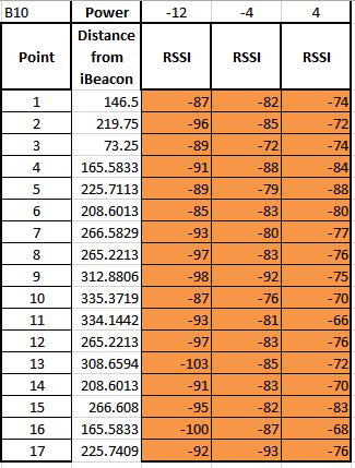
17 3.1 ibeacon Coverage Design Goal This section was accomplished by configuring beacon locations in a room and checking the RSSI values at multiple points in the room. Essentially, RSSI measurements were taken at multiple points with multiple configurations and multiple dbm transmission levels. The ideal result is the most amount of coverage with the lowest power setting to ensure any person in the room can be tracked and the battery in the beacon will last as long as possible. We collected our data from Room 233 in Atwater Kent. Our first step was to collect data using five beacons in the room at the different available transmission levels that the beacon could be set at. These transmission levels were: -12 dbm, -4 dbm, and 4 dbm. The second data collection tested different selections of ibeacons in different locations. Ten possible locations for ibeacons were selected and the RSSI for each ibeacon in each location in the room was measured and graphed. In Figure 3.1, the testing locations of the ibeacons are shown. Figure 3.1: Initial Consideration for ibeacon Placement in Atwater Kent Room 233 to Ensure the Complete Coverage of the Room From these measurements of the multiple ibeacons, we determined that 5 ibeacons arranged in 17
18 the following configuration would be sufficient in providing coverage to the entire room. To test our determination, we placed the ibeacons in their respective locations and calculated the path-loss model and the RSSI measurements at seventeen points. The path-loss model is shown below in Figure 3.2 and the RSSI measurements are shown in Figure 3.3. In determining the path loss model, we used the IEEE model path loss equation given by: L o = 10log(G t ) + 10log(G r ) + 20log(λ/(4π)) (3.1) L p = L o + 10α 1 log(dpb) + 10α 2 log(d/dpb) d < dpb The assumptions made in this equation were that the gain is 0, the room is a typical office environment and alpha a = 2. We also assumed, based on a phone s sensitivity to RSSI, that an acceptable path loss was 85. Figure 3.2: Path-Loss Color Gradient Graphic of Atwater Kent Room 233 Using Chosen Beacon Configuration to Provide Sufficient Room Coverage This conclusion was supported by our data measurements of RSSI, which is shown in Figure
19 as a gradient of colors based on the measurement at each of points in the room. The dark green means the signal from the ibeacons was the strongest, and as you can see the majority of the room is well covered, with only one point (8) displaying a RSSI of above -95dbm. However, we still have 4 additional readings from the other ibeacons which will enable the Phone Application and Location Algorithm to successfully determine both if a person is in the room and their location at point 8, despite the one questionable reading. Figure 3.3: RSSI Color Gradient Graphic of Atwater Kent Room 233 Using Chosen Beacon Configuration to Provide Sufficient Room Coverage 3.2 Smartphone Application The application for interacting with the beacons is developed for Android. This mobile OS allows programmers to develop for free and easily be downloaded onto other phones without having to go through an official app store or modifying the phone. To assist in application development, the group is using the Estimote app which can be found on the Google Play Store. Figure 3.4 is a screenshot of the application locating two nearby beacons. 19

20 Figure 3.4: Estimote Application Demonstrating that Two Unique and Identifiable Beacons are Currently in Range of the BLE Capable Device This application has some functions, but serves as a demonstration of Estimote ibeacon technology rather than a full-fledged application. It allows the user to check distance from any individual beacon and shows what kind of text, images, or data can be sent from beacons. The end goal of the application is to have the smartphone use the location algorithm being developed to determine location. It will then send location, user ID, and a time signature to a server. This will be repeatedly sent at a certain interval to keep track of any users who leave a room. Since the real accuracy of the Estimote Location Beacon is reported to be forty to fifty meters, nine devices were ordered. A joint group was made to establish ownership of the beacons so data can be read and the settings of the beacons can be changed. By default, the beacons are named after their color. In these sets, there are two named lemon (the yellow devices), beetroot (maroon devices), and candy (pink devices). As a basic form of interaction with the devices the group renamed two of the devices. It is important to note that only the Estimote account associated with the address 20


21 can rename the devices. In this case, the name lemon was changed to Sunny. As this happened, the physical device began to emit a white light, which is pictured here in Figure 3.5. Figure 3.5: Estimote Beacon Producing Light to Notify User that the Beacon is Being Reconfigured by Owner Only the beacon that is being modified is emitting a light. The maroon beacon right behind it can still be detected by the phone but does not receive data for a name to be changed. This is evidence that each beacon can be interacted with individually even if there are multiple in range. To confirm these changes work correctly, the beetroot beacon was renamed to Beats. Finally, both beacons were checked for names and UUID as seen in Figure 3.6. Figure 3.6: Interaction with Beacons Demonstrating the Reconfiguration of the Name of the Beacon was Successful 21
22 This figure is very important for a number of reasons; it shows that we can permanently make changes to the programming of the beacons, it shows that we can receive the signal strength to determine distance, and it shows the UUID of each device can be read by the phone. Any other phone will now be able to interact with the newly named beacons even without the owner Estimote account. Once we fully understood how to interact with the beacons using a phone application, we developed our own. The application was developed for Android smartphone devices using Android Studio. It is compatible with any device using Bluetooth 4.0 and newer. This includes all smartphones running Android 4.3 (released July 24, 2013) and newer. 3.3 Design of Algorithms The process of localization is done via Trilateration. Trilateration, which is very similar to ranging, involves the use of known transmitter locations and Received Signal Strength information to estimate the distance of the receiver. There are two major forms of trilateration; Ideal and Real. Ideal Trilateration, as shown in Figure 3.7 involves finding the distance from at least three points. These distances are the radii of three circles which represent all possible locations that the receiver could be located. The radii is determined by the RSS data as a function of path loss. The exact location of the receiver is then calculated using the intersection of the three circles based on the equation of a circle which mimic the distance formula. The square root of d in equation 3.4 is the same as radius of a circle. (x 1 x 0 ) 2 + (y 1 y 0 ) 2 2 = d 1 (x n x 0 ) 2 + (y n y 0 ) 2 2 = d n (3.2) d - distance n nth access point, xn, yn - coordinates for i th location, x0, y0 coordinates for reference point, and i = 1, 2, 3,. 22
23 Figure 3.7: Ideal Trilateration for 3 Transmitters (ibeacons) with intersection (x0, y0) as the Location of the Receiver The team was able to collect more than 300 points on RSS, distance, and power for the calculation of path-loss, variance, and Distance Measurement Error (DME). This information was used to develop graphs to compare the following algorithms to the Cramer Rao Lower Bound (CRLB) for accuracy: Trilateration, Centroid and Least Square. The first step in comparing location algorithms was to accurately calculate path-loss modeling which is shown in Equation 3.2. C = 3*10 8 m/s F = 2.4*10 9 Hz λ= C/f= ⅛ = Lo = -20log (λ/(4π)) = 40.5 db Lp = Lo+10α log (d/d0) α = 2.5 (3.3) 23
24 Sigma used was from a typical environment type C that is approximately 5 according to Principles of Wireless Access and Localization [1]. The calculated attenuation for the project's path-loss model was 2.5 although the expected value is between 1.6 and 1.8 for an indoor location in a line of sight setup. This is due to interference from noise, wifi, other transmitting devices and even shadow fading. C is the speed of light in a vacuum. The F is the frequency of the transmitting node. Lo is path loss for a 1 meter distance while Lp is the path-loss with respect to a particular location based on RSS. Trilateration alone is not enough to produce an accurate estimation of location. Because of this, other algorithms were considered and evaluated to provide better estimations. The Centroid and Least Square Algorithm were compared to ranging and CRLB Centroid Algorithm In Centroid Localization, each transmitter advertises its location and RSS to the receiver, which forms a polygon. Based on this polygon, the receiver uses the average of the center as its approximated location. This method is prone to error depending on the number of nodes it receives information from. The higher the number of nodes, the more the accuracy in estimating the location of the receiver. Centroid algorithm assumes a beacon range or coverage is in the form of a circle. It is dependent on information from the transmitters (ibeacons) and it uses the node s location information. The nodes that centroid is dependent on are always fixed in the setup environment no matter how the beacons are distributed or set up in a room, centroid will give the estimated location based on the mean or the average of the distances between the beacons. Despite the fact that it is not very accurate, it is still one of the simplest algorithms to work with and also has modified versions like weighted centroid to improve accuracy. 24
25 mu i (x,y)=(1/m) Σ m j=1 B j (x,y) (3.4) U i (x,y) : unknown position of receiver B j (x,y) : Known position of ibeacon. m: number of transmitters LMS Algorithm Least Square is an iterative algorithm that provides a method of estimating x and y as shown below. The algorithm iterates based on guessed value to calculate the position of the unknown node (receiver). The fewer the iterations, the closer the guessed value. Iteratively the error in the solution reduces as the iterations increase since new error is added to old error until the solution stops changing as demonstrated in Equation 3.5. Suppose [ f 1 (x,y) f 2 (x,y) f N (x, y)] T f 1 (x,y) x If jacobian matrix J = [ f N (x,y) x f 1 (x,y) y ] (3.5) f N (x,y) y An estimate of the solution picked U = [x*,y*]. The error in the solution is determined as E = - (J T J) -1 J T F evaluated at estimate U. Thus the new solution is U + E [1] 3.4 Performance Evaluation with Cramer Rao Lower Bound Cramer Rao Lower Bound is the lowest value of variance of an estimator. This bound is used to compare the theoretical minimal DME using RSS with results of different algorithms finding the location using the RSS from deployed Beacons. It is used to determine how far off the developed Android 25
26 Application DMEs are by comparing them to the CRLB Cramer Rao Lower Bound for Ranging The CRLB is calculated using the inverse of Fisher Information Matrix. For a single beacon and a single RSS reading, we observe, O, which is the RSS given by Equation 3.6. O = P r = P 0-10α log d + X (3.6) Equation 3.6 was used to relate the observation O (the received power Pr ) to probability distribution function of the observation given the distance: f(o/d) = ( 1 (Pr P0 +10α log d) 2 2πσ )e 2σ 2 (3.7) The probability distribution function (Equation 3.7) of the observation point was used to find to find the Fisher matrix, which is shown in Equation 3.8. CRLB is shown on equation 3.9 as the inverse of the Fisher equation. It is also the variance of estimate (σ 2 ) E [ 2 ln f(o/d) d 2 ] = E [ ln f(o/d) ] 2 = [ d 10α (ln 10)σd ]2 (3.8) CRLB = F 1 = σ 2 (ln 10)σd = [ 10α ]2 (3.9) i = 1, 2, 3,, N O is the observation being measured, α represents the parameter being measured. f(o/d) Represents probability distribution function of the observation based on the observation and the parameter. A single location has zero or no Gaussian noise, x = 0. For multiple points, O changes as shown below and the Fisher equation is multiplied by number of observations (N). σ 2 is variance while standard deviation is the square root of variance[1]. 26
27 This equation can be extended for multiple points (N). Since the N depends on the number of observations, Fisher equation is repeated with a change in the observation point O for the desired number of points. Fisher equation is then multiplied by N to match the number of N observations Cramer Rao Lower Bound for Localization Localization in a 2D environment required the use of CRLB for localization. This variance estimator is normally used on locations with RSS values and coordinate information of the transmitters (ibeacons). The location of the reference points (x i, y i ) and the access points (x,y) are used to calculate and estimate the location of the received power dp as depicted in Equation 3.10 [1]. dp i (x,y) = - 10α i ln10α (x x i r2 dx + y y i i r2 dy) i = 1, N, (3.10) i The range estimate dr was then used to dp in vector form as shown in Equation dp = Hdr dr = (H T H) -1 H T dp dp = dp 1 dp 2 dp N dr = dx dy H = [ x x i r i 2 y y N r N 2 y y i r i 2 y y N r N 2 ] (3.11) The covariance of the location estimate was used due to the shadow fading being a zero Gaussian random variable as shown in Equations 3.12 and cov(dp i, dp j ) = { σ2, i = j 0, i j i, j = 1,2,.. N (3.12) cov(dr) = σ 2 (H T H) 1 = [ σ x 2 2 σ xy 2 σ y 2 ] (3.13) σ xy σ r = σ x 2 + σ y 2 27
28 3.5 Server and User Interface To accomplish the tasks of collecting and managing the data provided by the Phone Application, this project uses a DropBox Server and an Excel program to input the data and organize into a user friendly graphic interface. The Graphic Interface is located on the DropBox Server for access from any computer with the correct username and passcode. To accomplish the task of creating a server and user interface, multiple server possibilities were entertained. The first was to use Amazon Web Services which offers a broad set of possible services such as global computation, storage, database, application and deployment services. Amazon Web Services would allow the group to make a website that was accessible from any computer and was graphically pleasing and easy to use. However, this service was found to be beyond the scope of this project due to a lack of experience in the coding needed to create a website. In addition, to successfully launch a website, there is no option but to pay monthly for it. The project also hit the roadblock that there was a lack of availability to successfully link a Phone Application to the website. Though it is possible to do this, it requires more background knowledge then what our team possesses. Due to these difficulties an alternative was discovered for proof of concept. Instead of using Amazon Web Services, this project is utilizing the free service known as DropBox. DropBox is set up on your computer just like a folder on your hard drive, except the files on this folder automatically sync online to any other computer or mobile device linked to that account. To fulfill the proof of concept for this project, the Phone Application will be sending its information to a text file on a designated DropBox folder. In this DropBox folder, there is an Excel File which automatically imports the information from this text file and sorts it by username, date, time and class. To automatically import information, the excel file uses a combination of macro s and Visual Basic, the code for which is provided in Appendix A. It imports the data and then uses a combination of graphs, pivot tables and slicers to represent the data. 28
29 4.0 Results and Discussion Overall the methodology for each component of our system was successful in producing results. The first set of results was ibeacon Coverage Design. After collecting data we determined that in AK 233, five beacons transmitting at a power of -4 dbm would provide the coverage required. The rest of this results section covers algorithm evaluations, smartphone application, and server interface results. 4.1 Algorithm Evaluations A simulation of four Beacons in a room was run in Matlab as seen in Figure 4.1. It shows the coverage probabilities of each Beacon in relation to changing distance. The yellow is the strongest and the closest coverage of the ibeacon while dark blue is the lowest strength. The white part is due to noise and surrounding interference including shadow fading. It is due to 90% shadow fading margin which is determined by the coverage possibility based on distance from transmitter (ibeacon). The coverage is calculated using path loss formula (Shown in Equation 3.2) except that a fade margin (X) is added to it. Adding a fading margin to the estimate increases the probability of coverage on operating with minimum signal strength. Shadow fading causes variations in average RSS and decrease in power as the distance between transmitter and receiver increases. 29

30 Figure 4.1: Coverage Probabilities Matlab Contour Simulation for 4 ibeacons based on Distance from Transmitter As a result of this coverage, we were able to test different algorithms and determine which should be used to give the best accuracy. The first algorithm that we tested was the Centroid Algorithm as shown in Figure 4.3.Using Matlab we ran the Centroid Algorithm using 4 Beacons in room 207. We found that no matter where the Beacons were placed in the room, the algorithm will always give you the location in center of the room as displayed by Figure 4.2. This causes this algorithm to have a large error, and therefore unreliable for our project. 30
31 Figure 4.2: Centroid Algorithm Showing the Intersections of the beacons coverage and the mean of the distances between them Figure 4.3: Centroid Algorithm Matlab Localization Results with the Calculated Coordinates of the Receiver. The second algorithm that we tested was the Trilateration Algorithm. Using data collected from room 207 in Atwater Kent we ran a Matlab simulation of RSS ranging localization (Trilateration) as shown in the Figure 4.4 and Figure 4.5. The closer the intersection of the circles, the better the accuracy of the algorithm. In some cases the circles did not intersect, which makes it prone to a larger error when approximating the location of a receiver. Having more transmitting devices, thus more coverage and 31
32 intersections of the circles increases the accuracy of the algorithm. The locations, indicated by a star, are of a receiver based on RSS from the surrounding access points. This algorithm ended up being better than the Centroid Algorithm however still unreliable especially when the circles do not intersect. Figure 4.4: Simulation of Trilateration for Location 1 with 4 circles intersecting at approximately (1.13, 1.12) 32
33 Figure 4.5: Simulation of Trilateration for Location 3 with 4 Circles Intersecting at Approximately (2.45, 2.52) The final Location Algorithm we tested was the Least Mean Square. Figure 4.6 shows the results obtained from simulating Least Mean Square in Matlab. Point 3 is invisible because it is very close to where the algorithm estimates as the location of the receiver (point 4). The numbers in the diamond shapes are the iteration numbers. In this case, the coordinates of the receiving node is approximately for y and for x. This algorithm is by far the most accurate with a final error percentage of 0.069%. This error is well within the acceptable threshold of 10%, which makes it a good fit for this project. 33

34 Figure 4.6: Results for LMS Algorithm based on iteration of guessed location value. The largest number is the calculated location of the receiver. To analyze and compare the location algorithms, we used the CRLB as shown in Figures 4.7 and 4.8. The graphs display the accuracy of location determination based on distance from four Beacons (4.7) and five Beacons(4.8). The locations where the beacons were located based on the path-loss modelling figures used to determine best positions for the access points. The yellow and green parts of the figures have closer contours which represents lower Cramer Rao values with better coverage while the dark blue parts have higher CRLB values and spaced out contours. The further apart the contours, the further a receiver is from the transmitter, and the lower the coverage[3]. 34


35 Figure 4.7: Matlab Contour Simulation for the 4 ibeacons estimate location error Installed in Room AK 207 Figure 4.8: Matlab Contour Simulation for the 4 ibeacons estimate location error Installed in Room AK
36 Using Matlab, our final step in Location Algorithm analysis was to compare the CRLB to the different algorithms as shown in Figure 4.9. The algorithm that is closest to CRLB is the Least Square Algorithm, meaning that it is by far the most accurate of the algorithms we analyzed. Therefore this is the algorithm we implemented in the phone application. The ranging data in the graph was calculated by the difference between actual measured error and application distance given by the ibeacon Scanner Application developed by Flurp [36], which was used to obtain RSS values. This gives the cumulative probability as a function of distance error, represented as Data in the graph. Cumulative probability is the percentage chance that a variable falls within a set range. In short, a higher cumulative probability per amount of DME is better. Figure 4.9: Cumulative Probability of Distance Measurement Error of LMS, Centroid Algorithm, and Ranging Crammer Rao Lower Bound Model. When the phone application runs this on multiple sets of Beacons, a user s location is determined with a percent error of 0.069%. Typically, and error of less than 10% is considered acceptable so this result is extremely good. This algorithm was successfully implemented on the developed smartphone 36
37 application. 4.2 Smartphone Application Results When the user opens the application on their phone they are prompted with a screen as shown in Figure This figure shows where the user can input their name and password or ID number. They also have the option to enable or disable when they are being monitored to protect their privacy. Once they accept being monitored, they can keep the app open or allow it to run in the background. Figure 4.10: Developed Smartphone Application Screen Including Fields for Name, Password and Monitoring Switch Once the device picks up the signal from the ibeacons, a message will display to the user. Figure 4.11 is an example of one such message. 37

38 Figure 4.11: Developed Smartphone Application Message Confirming that the User s Attendance has been Successfully Accounted for as Displayed in Red Rectangle In this example, the user is informed that they are in a professor s office. This is a confirmation that the user is being tracked. The message can be customized depending on which ibeacons they are near. This application then sends the name, time, and location to a text file located on the Dropbox server. 4.3 Server Interface Results Next, the excel file imported this information and created pivot tables, pivot graphs and slicers to represent the data. The text file created is shown below in Figure The image shows the username, date, time, room number and simulated location coordinates as they would be imported into the excel file. 38


39 Figure 4.12: Text File Located on Drop Box Server Used for Information Depository for Data Sent from Developed Smart Phone Application To automatically import this data into the excel program, a macro is used which records set of instructions to perform a particular task that is summed up in a single instruction. This macro is called in a command button program which is displayed as a button on the main sheet. The macro is called Refresh and the code is display in Appendix B into the visual basic command button. After inputting the data, a program is run that compares the times, dates and room number against a database of the known classes that are included in our a separate page of the excel program. The raw data is shown below in Figure Also note that the button to the right is the command button referenced earlier. It both refreshes the data inputted by the phone as well as determines what class each person is in. Figure 4.13: Raw Data Imported from Text File Located on Drop Box Server with Command Button Program Using Visual Basic The next step to designing this graphic is to display this information in an easy to understand table. 39

40 To do this we used a pivot table which allows us to select the data we want to see, and to filter out what we don t. The pivot table, is shown below in Figure This table is a way to display how many times a user goes to each of their classes total. As shown in the figure, you can select which user you want to see, in this case it is on selection snredetzke. The data is shown in the Count of Date row, which counts how many times you attended each class, and at the end it shows the Grand Total which totals how many times you went to all the classes combined. Figure 4.14: Pivot Table Displaying Attendance for user snredetzke Displaying the Number of Days they Attended Class You can also add in the actual dates into the rows to display the days on which they went to class, as shown below in Figure As displayed in the figure, you can also see that how many classes on any particular date each student attended, based on chosen person in the user filter. Figure 4.15: Pivot Table for Displaying the Individual Dates that User snredetzke Attended Class in Addition to the Grand Total of Classes Attended However, tables can be hard to read, so there are two other ways this excel program can display the data for easy comprehension. The first is in graph form. The graph is linked to the pivot table above. 40
41 It changes based on the information you select for the table to display. For Figure 4.15, data, the table displays the information in bar form as shown in Figure This graph displays the user snredetzke and which classes they attended, how many times. The user snredetzke attended ECE 2310 a total of two times for instance, as displayed by the orange bar. Figure 4.16: Bar Graph Displaying Class Attendance of snredetzke Using Piviot Table Referenced in Figure 4.15 The other way to display this data is though what is called a slicer, as shown below in Figure It takes the data and allows you to sort it by user, room number, time and class. For instance, if you wanted to determine who had class in a particular room at all, select what room you want and the other sections will update to reflect that data that it has on that particular room. As you can see, all the data is reflected in four main boxes, class, user, time and room. 41

42 Figure 4.17: Imported Data Organized in Slicer Form Representing the Class, User, Time and Room with the Potential to Filter the Information To select information, you need only click on one of the pieces of data. The data that pertains to the information you selected is stays highlighted blue, while the data that doesn t pertain to it is removed from the slicer, as shown in Figure

43 Figure 4.18: Imported Data Organized in Slicer Form Representing the Data only from the Selected Room, 233 Selecting the room number tells you that both users, atvanner and snredetzke, took multiple classes in that room, if you are looking for something even more specific you can select a class, or time to narrow the range even further. For instance if you select a specific class such as CS2102 as shown in Figure 4.19 it removes information that doesn t meet both the class and room criteria. The information you are left with tells you that only user snredetzke takes that class in room 233, and the last time she was recorded as being there was at 1335, and 1:35. 43
44 Figure 4.19: Imported Data Organized in Slicer Form Representing the Data only from the Selected Room, 233 and Class CS
45 5.0 Conclusions and Future Work In the end this project met the design specifications set forth. We took the problem of Attendance Monitoring and created a new system to improve on the problem s lack of efficiency. After researching location algorithms and BLE technology, we created a system that uses multiple components working together. Using a combination of BLE beacons, a smartphone application, and a computer server, the entire process of attendance monitoring is complete. The beacons were set up in a way that offers maximum coverage of a room. In addition, the configuration considered power usage and expected battery life to make it more appealing to expense-savvy businesses. The least means square algorithm implemented provides a very accurate estimation of location. It is the closest to the CRLB of the given algorithms and offers an extremely small distance measurement error of 0.69%. The smartphone application is straightforward and easy for new users to understand. It is able to run this algorithm and send the data to a server, which gives certain users access to information they never had before. There are always ways products can be improved and this project is no exception. To bring it to market there would be a real private server that has upkeep costs. In addition, the data being sent would be encrypted. The computer server application would be a website that takes a username and password so the right person could access the data anywhere. Also, more clients could be reached if the phone application was also built for ios devices. This project has potential for future use in business and academia. A college professor could check which students come to class the most and even where they sit and see if that can affect their grades. In addition, faculty could see if certain classrooms lead to higher or lower amounts of attendance. Overall, this method is faster than manually swiping students in or having an attendance sheet while providing more data. 45
46 REFERENCES 1. K. Pahlavan and P. Krishnamurthy, Principles of Wireless Access and Localization, Wiley, November Yi Sun, Olawole Tunde-Lukan, and Teng Weng, ECE, ibeacon Applications and Hybrid Wi-Fi Localization, MQP 3. Yang, Yang, "Application Performance Evaluation for. In Cognitive Methods in Situation Awareness and Decision Support (CogSIMA), 2016 IEEE International Multidisciplinary Conference on, pp IEEE, Nayef Alsindi, Ind HYPERLINK " Cooperative Localization for Ultra Wideband Wireless Sensor Networks, "Sign In: Registered Users." International Journal of Distributed Sensor Networks. N.p., n.d. Web. 13 Apr "What Is Ibeacon? A Guide To Ibeacons" Ibeacon.Com Insider "A BLE Advertising Primer." Argenox Technologies. N.p., n.d. Web. 13 Apr HYPERLINK " HYPERLINK " 8. Estimote. What Is IBeacon? - Estimote Developer N.p, n.d. Web.13 Apr What is IBeacon? A Guide to IBeacons. IBeacon.com Insider. N.p, 12 June Web 13 Apr Li, Dong, and Jiancheng Wang. Research of Indoor Local Positioning Based on Bluetooth Technology th International Conference on Wireless Communications, Networking and Mobile Computing (2009) n. pag. Web HYPERLINK " org/2961/435e73a d3e89d24ce20429f74d.pdf 11. Lewars, Giselle and Minh Truong Performance Study Of Mtx Motion Tracker Technology For Indoor Geolocation. Ebook. 1st ed. Worcester Frenzel, Lou "What S The Difference Between Bluetooth Low Energy And ANT?". Electronicdesign.Com. 13. Zeynep Turgut, Gulsum Zeynep Gurkas Aydin, Ahmet Sertbas, Indoor Localization Techniques for Smart Building Environment, Procedia Computer Science 14. Lixiong Tan, Fei Luo and Kai Liu, "Weighted centroid location algorithm in Wireless Sensor Network," IET International Communication Conference on Wireless Mobile and Computing (CCWMC 2011), Shanghai, 2011, pp Kwang-Yul Kim, Yoan Shin, "Test node-based WCL algorithm for wireless sensor networks", Ubiquitous and Future Networks (ICUFN) 2016 Eighth International Conference 46
47 16. "A BLE Advertising Primer Argenox Technologies" Argenox.Com "Beecon" Beaconsandwich.Com. HYPERLINK " 18. "Bluetooth Vs. Bluetooth Low Energy" Link Labs Contreras, David, Mario Castro, and David Sanchez de la Torre "Performance Evaluation Of Bluetooth Low Energy In Indoor Positing Systems". Emerging Telecommunications Technologies Frenzel, Lou "What s The Difference Between Bluetooth Low Energy And ANT?". Electronicdesign.Com Based Micro-Location with Particle Filtering Global Communications Conference, 2015 IEEE Alexandre Alapetite, John Paulin Hansen Dynamic bluetooth becons for people with disabilities Internet of Things (WF- IoT), 2016 IEEE 3 rd World Forum, Naoki Honma, Kazuki Ishii and Yoshitaka Tsunekawa DOD-based locailization technique using RSSI of indoor beacons Antennas and Propagation (ISAP), 2015 International Symposium, A. Coma, L. Fontana, A. A. Nacci Occupancy detection via ibeacon on Android devices for smart building management Design, Automation and Test in Europe Conference & Exhibition (DATE), 2015, Zhouchi Li, Yang Yang, Kaveh Pahlavan, "Using ibeacon for newborns localization in hospitals", Medical Information and Communication Technology (ISMICT) th International Symposium on, pp. 1-5, 2016, ISSN Zhiheng Zhao, Ji Fang, George Q Huang, Mengdi Zhang, ibeacon enabled indoor positioning for warehouse management Computational and Business Intelligence (ISCBI), th International Symposium on, Yingying Guo, Yatao Li, Yan Sun, Accuracte Indoor Localization based on Crowd Sensing, Wireless Communications and Mobile Computing Conference (IWCMC), 2016, ISSN Louay Bassbouss, Gorkem Guclu, Stephan Steglich, Towards a remote launch mechanism of TV companion applications using ibeacon, Consumer Electronics (GCCE) 2014 IEEE 3 rd Global Conference on, Yang Yang, Zhouchi Li, Kaveh Pahlavan, "Using ibeacon for intelligent in-room presence detection", Cognitive Methods in Situation Awareness and Decision Support (CogSIMA) 2016 IEEE International Multi-Disciplinary Conference on, pp , 2016, ISSN Miller. Steven, The Method of Least Squares 31. "Gale - Enter Product Login". Go.galegroup.com. N.p., Web. 25 Apr
48 32. ibeacon and Eddystone Scanner created by Flurp Laboratories 48
49 Appendix A: Code for Beacon Placement in Room AK207 %%%Plot for AK 207 with corresponding beacon placement %%%and distance from receiver (phone) % function h = circle(x,y,r) close all; clear all; clc; ch = 1;% to continue entering information while(ch~=2) % choice 2 is for quitting rectangle('position',[ ]) axis([ ]) %********************************* % x = [0,0,2,2.5,4,4.5,6.5,6.5];%* % y = [0,2,2,2.5,2.5,2,2,0]; %* Modified for Room % fill(x,y,'k'); %* AK233 & any other % axis([ ]) %* %********************************* hold on th = 0:pi/50:2*pi; fprintf('what is the radius of the circle\n'); r = input('give radius size\n'); fprintf('where do you want to draw circle\n'); x = input('give x-location\n'); y = input('give y-location\n'); xunit = r * cos(th) + x; yunit = r * sin(th) + y; plot([x], [y], '*', 'MarkerSize', 7); h = plot(xunit, yunit); title('trilateration Location Algorithm') xlabel('x-location (m)'); ylabel('y-location (m)'); hold off fprintf('do you want to plot another circle\n'); ch = input('enter the choice\n'); end CODE FOR PATHLOSS & BEACON PROBABILITY clear all;close all;clc; %% basic path loss model alpha1=6.7.0; % power gridiant lpmax=85.5; % max path loss in db f=2.4e9; % transmitting frequency c=3e8; % speed of light 49
50 lamda=c/f; % wave length L0= ; % 1st meter path loss pace=0.5; reliablity = 0.9; %Distance=40; t = 1; o = 1; for Distance = 30:1:75; x1=distance/4;y1=distance/4; x2=distance/4;y2=3*distance/4; x3=3*distance/4;y3=3*distance/4; x4=3*distance/4;y4=distance/4; x=0:pace:distance;y=0:pace:distance; L1=length(x); r1=zeros(l1,l1); r2=zeros(l1,l1); r3=zeros(l1,l1); r4=zeros(l1,l1); for i=1:1:l1 for j=1:1:l1 r1(i,j)=sqrt((x(i)-x1)^2+(y(j)-y1)^2); r2(i,j)=sqrt((x(i)-x2)^2+(y(j)-y2)^2); r3(i,j)=sqrt((x(i)-x3)^2+(y(j)-y3)^2); r4(i,j)=sqrt((x(i)-x4)^2+(y(j)-y4)^2); end end lp1=l0+max(10*alpha1*log10(r1),-l0); lp2=l0+max(10*alpha1*log10(r2),-l0); lp3=l0+max(10*alpha1*log10(r3),-l0); lp4=l0+max(10*alpha1*log10(r4),-l0); alpha2=-4.28; beta=0.9372; gamma0=5.31; sigma1=alpha2*exp(-beta*r1)+gamma0; sigma2=alpha2*exp(-beta*r2)+gamma0; sigma3=alpha2*exp(-beta*r3)+gamma0; sigma4=alpha2*exp(-beta*r4)+gamma0; for p=1:1:l1 for q=1:1:l1 pc1(p,q)=1-0.5*erfc((lpmax-lp1(p,q))/sqrt(2)/sigma1(p,q)); pc2(p,q)=1-0.5*erfc((lpmax-lp2(p,q))/sqrt(2)/sigma2(p,q)); pc3(p,q)=1-0.5*erfc((lpmax-lp3(p,q))/sqrt(2)/sigma3(p,q)); pc4(p,q)=1-0.5*erfc((lpmax-lp4(p,q))/sqrt(2)/sigma4(p,q)); end end [c1,h1] = contour(x,y,pc1','w','levellist',[reliablity],'linewidth',3); R1 = sqrt((c1(1,2)-x1)^2+(c1(2,2)-y1)^2); if Distance == 60; subplot(2,2,1); [X1,Y1]=contourf(x,y,pc1',20); 50
51 xlabel('distance(m)'),ylabel('distance(m)'),title('the probabilities for Beacon1'); hold on; [c1,h1] = contour(x,y,pc1','w','levellist',[reliablity],'linewidth',3); R1 = sqrt((c1(1,2)-x1)^2+(c1(2,2)-y1)^2); clabel(c1,h1); subplot(2,2,2); [X2,Y2]=contourf(x,y,pc2',20); xlabel('distance(m)'),ylabel('distance(m)'),title('the probabilities for Beacon2'); hold on; [c2,h2] = contour(x,y,pc2','w','levellist',[reliablity],'linewidth',3); R2 = sqrt((c2(1,2)-x2)^2+(c2(2,2)-y2)^2); clabel(c2,h2); subplot(2,2,3); [X3,Y3]=contourf(x,y,pc3',20); xlabel('distance(m)'),ylabel('distance(m)'),title('the probabilities for Beacon3'); hold on; [c3,h3] = contour(x,y,pc3','w','levellist',[reliablity],'linewidth',3); R3 = sqrt((c3(1,2)-x3)^2+(c3(2,2)-y3)^2); clabel(c3,h3); subplot(2,2,4); [X4,Y4]=contourf(x,y,pc4',20); xlabel('distance(m)'),ylabel('distance(m)'),title('the probabilities for Beacon4'); hold on; [c4,h4] = contour(x,y,pc4','w','levellist',[reliablity],'linewidth',3); R4 = sqrt((c4(1,2)-x4)^2+(c4(2,2)-y4)^2); clabel(c4,h4); end end CODE FOR CALCULATING CRLB H MATRIX Rx=[1.5241,1.3398; ,1.3398;4.0200,1.3398;4.0200,3.0480; ,3.0480; ,3.0480;1.5240,4.5720; ,4.5720; ,4.5720]; Tx=[4.0200,3.0480]; % Coordinates for transmitter bp=5; % break point var=5; % variance for i=[1:1:4] r(i)=sqrt((tx(1)-rx(i,1)).^2+(tx(2)-rx(i,1)).^2); if r(i)<5; a1=6.7; % alpha in free space P(i)=-10*a1/log(10)*((Tx(1)-Rx(i,1))/(r(i).^2)); Q(i)=-10*a1/log(10)*((Tx(2)-Rx(i,2))/(r(i).^2)); H(i,1)=P(i); %H matrix left column H(i,2)=Q(i); %H matrix right column end if r(i)>=5; a2=4.5; % alpha in obstructed room 51
52 P(i)=-10*a2/log(10)*((Tx(1)-Rx(i,1))/(r(i).^2)); Q(i)=-10*a2/log(10)*((SD(2)-Rx(i,2))/(r(i).^2)); H(i,1)=P(i); H(i,2)=Q(i); end end CRLB=var^2*inv(H'*H) plot(crlb); CODE FOR CONTOUR LOCATION ERROR close all; clear all; clc; APx(1) = 4.55; APy(1) = 5.35; APx(2) = 4.55; APy(2) = -5.35; APx(3) = -4.55; APy(3) = -5.35; APx(4) = -4.55; APy(4) = 5.35; APx(5) = 0; APy(5) = 0; SD = 5; NUM = 5; mx = -5.35:0.1:5.35; my = -5.35:0.1:5.35; nxy = length(mx); for yi = 1:nxy for xi = 1:nxy for i1 = 1:NUM alpha(i1) = 6.7; r(i1,xi,yi) = sqrt((mx(xi)-apx(i1))^2+(my(yi)- APy(i1))^2); H1(i1,xi,yi) = -10*alpha(i1)/(log(10))*(mx(xi)- APx(i1))/r(i1,xi,yi)^2; H2(i1,xi,yi) = -10*alpha(i1)/(log(10))*(my(yi)- APy(i1))/r(i1,xi,yi)^2; end H(:,:,xi,yi) = [H1(:,xi,yi) H2(:,xi,yi)]; Covv(:,:,xi,yi) = SD^2*((H(:,:,xi,yi)'*H(:,:,xi,yi))^(-1)); SDr(xi,yi) = sqrt(covv(1,1,xi,yi)+covv(2,2,xi,yi)); end end SDr = SDr'; contourf(mx,my,sdr,20); xlabel('x-axis(meter)'); ylabel('y-axis(meter)'); title('contour of Location Error Standard Deviation(meter)'); 52
53 CODE FOR LEAST MEAN SQUARE %function [final_x,final_y] = LMSforMQP known_references = [1.8,2.4;1.8,3.7;2.3,2.5]; initial_guess = [1.93, 2.454]; distances = [ ,0.850,0.4933]; if size(known_references,2) ~= 2 error('location of known reference points should be entered as Nx2 matrix'); end figure(1); hold on grid on i=1; temp_location(i,:) = initial_guess ; temp_error = 0 ; for j = 1 : size(known_references,1) temp_error = temp_error + abs((known_references(j,1) - temp_location(i,1))^2 + (known_references(j,2) - temp_location(i,2))^2 - distances(j)^2) ; end estimated_error = temp_error ; % new_matrix = [ ]; while norm(estimated_error) > 1e-2 %iterative process for LS algorithm for j = 1 : size(known_references,1) %Jacobian has been calculated in advance jacobian_matrix(j,:) = -2*(known_references(j,:) - temp_location(i,:)) ; %partial derivative is i.e. -2(x_1-x) f(j) = (known_references(j,1) - temp_location(i,1))^2 + (known_references(j,2) - temp_location(i,2))^2 - distances(j)^2 end estimated_error = -inv(jacobian_matrix' * jacobian_matrix) * (jacobian_matrix') * f' ; %update the U and E temp_location(i+1,:) = temp_location(i,:) + estimated_error' ; % current_point = [temp_location(i+1,1),temp_location(i+1,2)]; % new_matrix = [ new_matrix; current_point]; plot(temp_location(i+1,1),temp_location(i+1,2),'rd','markerfacecolor','g','markersi 53
54 ze',20) ; % plot text(temp_location(i+1,1), temp_location(i+1,2), num2str(i)); drawnow; i = i + 1; end final_x = temp_location(i,1) ; disp(final_x); final_y = temp_location(i,2) ; disp(final_y); title('lms Algorithm') CODE FOR CENTROID ALGORITHM function center = Centroidtest(points) mass = []; if nargin==1 %Array of points pts = points; %pts = [2 2;6 1;6 5;2 4]; elseif nargin==2 % either POINTS+MASS or PX+PY var = varargin{1}; if size(var, 2)>1 % arguments are POINTS, and MASS pts = var; mass = varargin{2}; else % arguments are PX and PY pts = [var varargin{2}]; end elseif nargin==3 % arguments are PX, PY, and MASS pts = [varargin{1} varargin{2}]; mass = varargin{3}; end %% compute centroid if isempty(mass) 54
55 % no weight center = mean(pts); else % format mass to have sum equal to 1, and column format mass = mass(:)/sum(mass(:)); end % compute weighted centroid center = sum(bsxfun(@times, pts, mass), 1); % equivalent to: % center = sum(pts.* mass(:, ones(1, size(pts, 2)))); 55
56 Appendix B: Code for Graphic Interface Excel Sheet Private Sub CommandButton1_Click() Refresh Refresh2 Worksheets("DATA").Range("A:F").Copy Worksheets("Working with Data").Range("A:F") Range("B1:B300").Copy Range("G1:G300") Date_to_Day Dim i As Integer Dim j As Integer Dim lngcount As Long lngcount = Application.WorksheetFunction.CountA(Columns(1)) classcount = Application.WorksheetFunction.CountA(Worksheets("Class List").Columns(1)) Range("H2:H300") = 0 For i = 2 To lngcount For j = 2 To classcount If CInt(Cells(i, 3).Value) >= CInt(Worksheets("Class List").Cells(j, 2).Value) And CInt(Cells(i, 3).Value) <= CInt(Worksheets("Class List").Cells(j, 3).Value) And CInt(Cells(i, 4).Value) = CInt(Worksheets("Class List").Cells(j, 4).Value) And StrComp(WeekdayName(Weekday(Cells(i, 7)), False), (Worksheets("Class List").Cells(j, 5))) Then Worksheets("Class List").Cells(j, 1).Copy Cells(i, 8) Next j Next i End Sub Sub Refresh2() ' ' Refresh2 Macro ' ' Sheets("Graphs").Select Range("A4").Select ActiveSheet.PivotTables("PivotTable").Name = "PivotTable" Range("C4").Select End Sub Sub Date_to_Day() ' ' Date_to_Day Macro ' 56
57 ' Columns("G:G").Select Selection.NumberFormat = "[$-F800]dddd, mmmm dd, yyyy" Selection.NumberFormat = "dddd" End Sub Sub Refresh() ' ' Refresh Macro ' ' ActiveWorkbook.RefreshAll End Sub Sub Refresh_Table() ' ' Refresh_Table Macro ' ' Sheets("Graphs").Select ActiveSheet.PivotTables("PivotTable1").PivotCache.Refresh End Sub Sub Collect_Data() ' ' Collect_Data Macro ' ' Sheets("DATA").Select Range("A:A,E:E,F:F").Select Range("F1").Activate Selection.Copy Range("A:A,E:E,F:F,D:D").Select Range("D1").Activate Application.CutCopyMode = False Selection.Copy Sheets("TABLE ").Select Columns("E:H").Select ActiveSheet.Paste Range("J10").Select Columns("F:F").ColumnWidth = 8.57 Columns("G:G").ColumnWidth = 5.29 Columns("H:H").ColumnWidth = 8.29 Range("J1").Select End Sub 57
58 Sub Sort_List() ' ' Sort_List Macro ' ' Range("A2:F9").Select ActiveWorkbook.Worksheets("DATA").Sort.SortFields.Clear ActiveWorkbook.Worksheets("DATA").Sort.SortFields.Add Key:=Range("A2:A9"), _ SortOn:=xlSortOnValues, Order:=xlAscending, DataOption:=xlSortNormal With ActiveWorkbook.Worksheets("DATA").Sort.SetRange Range("A1:F9").Header = xlyes.matchcase = False.Orientation = xltoptobottom.sortmethod = xlpinyin.apply End With End Sub Sub Application_Users_List() ' ' Application_Users_List Macro ' ' Sheets("DATA").Select Columns("L:L").Select Selection.Copy Sheets("DISPLAY").Select Columns("E:E").Select ActiveSheet.Paste Selection.ColumnWidth = Range("E1").Select Application.CutCopyMode = False ActiveCell.FormulaR1C1 = "Application Users" Range("E2").Select ActiveWindow.ScrollRow = 2 Range("E2:E21").Select ActiveWorkbook.Worksheets("DISPLAY").Sort.SortFields.Clear ActiveWorkbook.Worksheets("DISPLAY").Sort.SortFields.Add Key:=Range("E2:E9") _, SortOn:=xlSortOnValues, Order:=xlAscending, DataOption:=xlSortNormal With ActiveWorkbook.Worksheets("DISPLAY").Sort.SetRange Range("E1:E9").Header = xlyes.matchcase = False.Orientation = xltoptobottom.sortmethod = xlpinyin.apply End With 58
59 ActiveWindow.ScrollRow = 1 Range("F10").Select End Sub 59

60 Appendix C: Raw Data Collection for Measuring RSSI in Room 233. This data is based on multiple beacons in the room, labeled as B1 through B10. 60

61 61

62 62


63 63


64 64


65 The pathloss for room 233, using 5 of the 10 Beacons is shown below. The data below was collected from 207 while measuring RSSI from the Beacons. It includes the RSSI from each Beacon, how far away the ibeacon & Eddystone Scanner phone application said we were from the beacon, how far the actual distance was and the pathloss. 65

66 66
67 Appendix D: Conference Paper for ISENG 2017 Smart Room Attendance Monitoring and Location Tracking with ibeacon Technology Andrew Vanner, Savannah Redetzke, Raymond Otieno, Jahangir Rahman, Julang Ying, and Kaveh Pahlavan Center for Wireless Information Network Studies (CWINS) Worcester Polytechnic Institute (WPI), Worcester, MA, {snredetzke, atvanner, rhotieno, jrahman, jying, 67

68 Abstract Using the recently developed technology, ibeacon was developed by Apple Inc and uses Low Energy Bluetooth (BLE) which can be detected by phones that have the software Bluetooth 4.0 or above. In this project we utilized this technology and designed an attendance and location monitoring system at in-room events. We have developed a system to receive the necessary information from multiple ibeacons, derived the optimal placement, number and transmission power of each ibeacon, developed a phone application to send information such as user name, time, and location, to a server for data analysis and created an excel program to represent the data. In addition, we compared multiple location algorithms using Received Signal Strength indicator RSSI data to determine the most accurate localization for this system and created simulation results of Cramer-Rao low bound (CRLB) estimation of the location error model. We conclude our work by discussing the potential of further developing this system. Keywords ibeacon; Attendance; in-room; localization; phone application Introduction When large groups of people meet for events, conferences, and college classes, one of the largest logistically challenging problems is both taking attendance of who is present and keeping track of where they are. Current solutions to this challenge are both error prone and time consuming, such as registration tables and sign in sheets. This project has developed a new solution that will enable coordinators of events to have an automated system to monitor the attendance and where people are inside a room. In this paper, we utilized two main technologies. These technologies are: Bluetooth Low Energy (BLE) for ibeacon, Estimote Location Beacons and Location Algorithms. BLE is a wireless network connection which is used to exchange tiny and static radio signals within short distances. It has a low power consumption which makes ideal to be used in this project because it is easy to power and does not contribute to being an obtrusive addition to any designated space. BLE is also considered to be a crucial addition to the Internet of Things [6] BLE technology is contained within our second technology, ibeacon. ibeacon broadcasts unique signals that can be received by BLE enabled devices such as phones with Bluetooth 4.0 standard or above. ibeacon has been used in many location-based applications [8], such as intelligent in-room presence detection systems[1], indoor positioning systems[2][3], predicting interactions inside crowds based on ibeacon proximity detection [4][9], and the enabling of communication between companion applications and television [5]. In addition, the Beacon has been considered in systems for assisting people with disabilities to interact with an Internet of Things made possible through Beacons. [7] Figure 1: Esimote Location Beacons using BLE for promimity broadcasting for smart devices Their properties can be customized to alter power output and improve longevity. These Location Beacons, and corresponding phone application, can be used to determine RSSI values, the distance you are from an Estimote Beacon, and add information to each Estimote Beacon for it to *This project was sponsored by Worcester Polytechnic Institute, Electrical and Computer Engineering Department as a Major Qualifying Project (MQP) for senior undergraduate studies.
69 transmit to a mobile device. However, though the Estimote phone application was useful in determining RSSI values for location algorithm analysis, we used Android Studio to develop our own unique phone application so we could customize our system. Using our own phone application allowed us to extrapolate information about different location algorithms as well as run simulations to determine which algorithms would be the most accurate. The simulations included Cramer-Rao lower bound and how other algorithms compare to it based on distance measurement error. In addition to working with different location algorithms, we maximized the accuracy of the location algorithm by creating path loss models for different numbers of Beacons in various points of a large lecture hall at different power outputs. Using this we were able to optimize power output as well as coverage for the entire room. We then used this design and tested various location algorithms, before settling on the Least Mean Square algorithm. This algorithm is then run by the phone application to determine location in a room. The user is then able to input their personal information, which gets sent to an online server. At this point, a computer program can read this data and organize it for an administrator. This completes the attendance monitoring process. The rest of our paper is organized into three major sections. In section II we summarize our system architecture and how the pieces of our technology work together. In section III we describe our performance analysis, including path loss modeling, location algorithm accuracy and Beacon placement. In section IV we discuss the results, conclusion and the potential of this project. System Architecture The design architecture is broken down into 4 basic components as shown below in Figure 2. Number 1 represents the multiple Beacons required for both determining location and identifying when a person enters a room. Number 2 represents the smartphone that using the application that this project designed to detect the Beacons, utilize a location algorithm to determine where in the room it is, and submit identifying information to Number 3, the server, at regular intervals. The server stores this information to be accessed by Number 4, the computer graphic interface. 69

70 Figure 2: Project General Architecture Overview to demonstrate the general block diagram of the project and the lines of communication between different technologies included in the project For our proof on concept, we chose a lecture hall that was 15 by 7.5 meters large. It seats approximately 50 students. We determined that 5 Beacons would be sufficient to cover the entire area. When a phone comes into range of at least one of the Beacons located in the room, our phone application downloaded on to a smart phone detects the signal that the Beacon is producing. It then provides a prompt to the user of the smart phone to to inset their name and some kind of ID or password. They also have the option to allow themselves to be monitored. The application can determine which room the user is in based on the unique identification numbers of the Beacons, demonstrated in Figure 3. beaconmanager.checkforbeacons { while (MonitoringAllowed){ if (UUID == CertainNumber) display(messageforroom) Figure 3: Application Code. Using a beaconmanager class, the application checks the UUID of a Beacon to determine what region the user is in. It will then display a message for the room. The phone application also runs the location algorithm for the room based on the Least Mean Square It returns coordinates describing where in the room a person is located based on a predetermined coordinate system. This application sends the user a message when their location has been determined. This prompt screen is shown in Figure } }
Using ibeacon for Navigation and Proximity Awareness in Smart Buildings
 Project Number: KZP - AA5Z Using ibeacon for Navigation and Proximity Awareness in Smart Buildings A Major Qualifying Project Submitted to the Faculty of WORCESTER POLYTECHNIC INSTITUTE in partial fulfillment
IoT. Indoor Positioning with BLE Beacons. Author: Uday Agarwal
 IoT Indoor Positioning with BLE Beacons Author: Uday Agarwal Contents Introduction 1 Bluetooth Low Energy and RSSI 2 Factors Affecting RSSI 3 Distance Calculation 4 Approach to Indoor Positioning 5 Zone
Comparison of RSSI-Based Indoor Localization for Smart Buildings with Internet of Things
 Comparison of RSSI-Based Indoor Localization for Smart Buildings with Internet of Things Sebastian Sadowski and Petros Spachos, School of Engineering, University of Guelph, Guelph, ON, N1G 2W1, Canada
Using ibeacon for Newborns Localization in Hospitals
 Using ibeacon for Newborns Localization in Hospitals G.Hanitha,E.Shanthanu Bharathi,R.Suriya,S.Vilasini,R.Mahendran Department of Electronics and Communication Engineering, K.S.R. College of Engineering,
A Simple Smart Shopping Application Using Android Based Bluetooth Beacons (IoT)
") Advances in Wireless and Mobile Communications. ISSN 0973-6972 Volume 10, Number 5 (2017), pp. 885-890 Research India Publications http://www.ripublication.com A Simple Smart Shopping Application Using
Advances in Wireless and Mobile Communications. ISSN 0973-6972 Volume 10, Number 5 (2017), pp. 885-890 Research India Publications http://www.ripublication.com A Simple Smart Shopping Application Using
1. Product Introduction FeasyBeacons are designed by Shenzhen Feasycom Technology Co., Ltd which has the typical models as below showing: Model FSC-BP
 ,,,,,,,,,,,,,,,,,,,,,,,,,,,,,,,,,,,,,,,,,,,,,,,,,,,, FeasyBeacon Getting Started Guide Version 2.5 Feasycom Online Technical Support: Skype: Feasycom Technical Support Direct Tel: 086 755 23062695 Email:
Performance Evaluation of Beacons for Indoor Localization in Smart Buildings
 Performance Evaluation of Beacons for Indoor Localization in Smart Buildings Andrew Mackey, mackeya@uoguelph.ca Petros Spachos, petros@uoguelph.ca University of Guelph, School of Engineering 1 Agenda The
How to Configure ibeacons in Jamf Pro
 What is an ibeacon? ibeacon is a communication protocol developed by Apple on top of Bluetooth Smart technology. It allows developers to create mobile apps aware of location context provided by beacons.
MOBILE COMPUTING 1/29/18. Cellular Positioning: Cell ID. Cellular Positioning - Cell ID with TA. CSE 40814/60814 Spring 2018
 MOBILE COMPUTING CSE 40814/60814 Spring 2018 Cellular Positioning: Cell ID Open-source database of cell IDs: opencellid.org Cellular Positioning - Cell ID with TA TA: Timing Advance (time a signal takes
On Practical Selective Jamming of Bluetooth Low Energy Advertising
 On Practical Selective Jamming of Bluetooth Low Energy Advertising S. Brauer, A. Zubow, S. Zehl, M. Roshandel, S. M. Sohi Technical University Berlin & Deutsche Telekom Labs Germany Outline Motivation,
ANALYSIS OF BLUETOOTH LOW ENERGY BEACONS IN INDOOR LOCALIZATION POLICY AND APPLICATION JERRY R. GUO THESIS
 c 2018 Jerry R. Guo ANALYSIS OF BLUETOOTH LOW ENERGY BEACONS IN INDOOR LOCALIZATION POLICY AND APPLICATION BY JERRY R. GUO THESIS Submitted in partial fulfillment of the requirements for the degree of
CSRmesh Beacon management and Asset Tracking Muhammad Ulislam Field Applications Engineer, Staff, Qualcomm Atheros, Inc.
 CSRmesh Beacon management and Asset Tracking Muhammad Ulislam Field Applications Engineer, Staff, Qualcomm Atheros, Inc. CSRmesh Recap Bluetooth Mesh Introduction What is CSRmesh? A protocol that runs
IoT Wi-Fi- based Indoor Positioning System Using Smartphones
 IoT Wi-Fi- based Indoor Positioning System Using Smartphones Author: Suyash Gupta Abstract The demand for Indoor Location Based Services (LBS) is increasing over the past years as smartphone market expands.
BTLE beacon for 8262 DECT handset Engineering Rules
 BTLE beacon for 8262 DECT handset Engineering Rules 8AL90346ENAAed01 April 2017 Table of content 1. INTRODUCTION... 3 2. LIST OF ACRONYMS... 3 3. RECOMMENDED USE CASES... 3 3.1 BEACON EVENT... 3 3.2 LOCATION
Beacons Proximity UUID, Major, Minor, Transmission Power, and Interval values made easy
 Beacon Setup Guide 2 Beacons Proximity UUID, Major, Minor, Transmission Power, and Interval values made easy In this short guide, you ll learn which factors you need to take into account when planning
Localization in Wireless Sensor Networks
 Localization in Wireless Sensor Networks Part 2: Localization techniques Department of Informatics University of Oslo Cyber Physical Systems, 11.10.2011 Localization problem in WSN In a localization problem
The definitive guide for purchasing Bluetooth Low Energy (BLE) Beacons at scale
 Beacons at scale") The definitive guide for purchasing Bluetooth Low Energy (BLE) Beacons at scale If you re working on an enterprise Request For Quote (RFQ) or Request For Proposal (RFP) for BLE Beacons using any of the
The definitive guide for purchasing Bluetooth Low Energy (BLE) Beacons at scale If you re working on an enterprise Request For Quote (RFQ) or Request For Proposal (RFP) for BLE Beacons using any of the
Indoor Localization Alessandro Redondi
 Indoor Localization Alessandro Redondi Introduction Indoor localization in wireless networks Ranging and trilateration Practical example using python 2 Localization Process to determine the physical location
Hack Your Ride With Beacon Technology!
 Hack Your Ride With Beacon Technology! #kontakt_io Trevor Longino Head of Marketing & PR @trevorlongino @kontakt_io We help build the world s best proximity solutions 10 thousand+ clients! Welcome to the
Triangulation: A Complex System of Radio Frequency ID Beacons
 Triangulation: A Complex System of Radio Frequency ID Beacons Juan Soto: B.S. Electrical Engineering and B.A. Mathematics Research Mentor: Dr. Donald Estreich, PhD Stanford University Abstract Indoor GPS
idocent: Indoor Digital Orientation Communication and Enabling Navigational Technology
 idocent: Indoor Digital Orientation Communication and Enabling Navigational Technology Final Proposal Team #2 Gordie Stein Matt Gottshall Jacob Donofrio Andrew Kling Facilitator: Michael Shanblatt Sponsor:
Alzheimer Patient Tracking System in Indoor Wireless Environment
 Alzheimer Patient Tracking System in Indoor Wireless Environment Prima Kristalina Achmad Ilham Imanuddin Mike Yuliana Aries Pratiarso I Gede Puja Astawa Electronic Engineering Polytechnic Institute of
INTRODUCTION TO WIRELESS SENSOR NETWORKS. CHAPTER 8: LOCALIZATION TECHNIQUES Anna Förster
 INTRODUCTION TO WIRELESS SENSOR NETWORKS CHAPTER 8: LOCALIZATION TECHNIQUES Anna Förster OVERVIEW 1. Localization Challenges and Properties 1. Location Information 2. Precision and Accuracy 3. Localization
Comparison ibeacon VS Smart Antenna
 Comparison ibeacon VS Smart Antenna Introduction Comparisons between two objects must be exercised within context. For example, no one would compare a car to a couch there is very little in common. Yet,
Cellular Infrastructure and Standards while deploying an RDA
 Cellular Infrastructure and Standards while deploying an RDA Overview This whitepaper discusses the methods used while deploying an RDA into a field environment and dives into the standards used to judge
Indoor navigation with smartphones
 Indoor navigation with smartphones REinEU2016 Conference September 22 2016 PAVEL DAVIDSON Outline Indoor navigation system for smartphone: goals and requirements WiFi based positioning Application of BLE
Introduction to Mobile Sensing Technology
 Introduction to Mobile Sensing Technology Kleomenis Katevas k.katevas@qmul.ac.uk https://minoskt.github.io Image by CRCA / CNRS / University of Toulouse In this talk What is Mobile Sensing? Sensor data,
best practice guide Ruckus SPoT Best Practices SOLUTION OVERVIEW AND BEST PRACTICES FOR DEPLOYMENT
 best practice guide Ruckus SPoT Best Practices SOLUTION OVERVIEW AND BEST PRACTICES FOR DEPLOYMENT Overview Since the mobile device industry is alive and well, every corner of the ever-opportunistic tech
Mobile Positioning in Wireless Mobile Networks
 Mobile Positioning in Wireless Mobile Networks Peter Brída Department of Telecommunications and Multimedia Faculty of Electrical Engineering University of Žilina SLOVAKIA Outline Why Mobile Positioning?
B L E N e t w o r k A p p l i c a t i o n s f o r S m a r t M o b i l i t y S o l u t i o n s
 B L E N e t w o r k A p p l i c a t i o n s f o r S m a r t M o b i l i t y S o l u t i o n s A t e c h n i c a l r e v i e w i n t h e f r a m e w o r k o f t h e E U s Te t r a m a x P r o g r a m m
ibeacon Spoofing Security and Privacy Implications of ibeacon Technology Karan Singhal
 ibeacon Spoofing Security and Privacy Implications of ibeacon Technology Karan Singhal ABSTRACT Apple introduced ibeacons with ios 7, revolutionizing the way our phones interact with real- life places
Detection of Obscured Targets: Signal Processing
 Detection of Obscured Targets: Signal Processing James McClellan and Waymond R. Scott, Jr. School of Electrical and Computer Engineering Georgia Institute of Technology Atlanta, GA 30332-0250 jim.mcclellan@ece.gatech.edu
Optimized Indoor Positioning for static mode smart devices using BLE
 Optimized Indoor Positioning for static mode smart devices using BLE Quang Huy Nguyen, Princy Johnson, Trung Thanh Nguyen and Martin Randles Faculty of Engineering and Technology, Liverpool John Moores
Introduction. Introduction ROBUST SENSOR POSITIONING IN WIRELESS AD HOC SENSOR NETWORKS. Smart Wireless Sensor Systems 1
 ROBUST SENSOR POSITIONING IN WIRELESS AD HOC SENSOR NETWORKS Xiang Ji and Hongyuan Zha Material taken from Sensor Network Operations by Shashi Phoa, Thomas La Porta and Christopher Griffin, John Wiley,
Range Free Localization of Wireless Sensor Networks Based on Sugeno Fuzzy Inference
 Range Free Localization of Wireless Sensor Networks Based on Sugeno Fuzzy Inference Mostafa Arbabi Monfared Department of Electrical & Electronic Engineering Eastern Mediterranean University Famagusta,
ARUBA LOCATION SERVICES
 ARUBA LOCATION SERVICES Powered by Aruba Beacons The flagship product of the product line is Aruba Beacons. When Aruba Beacons are used in conjunction with the Meridian mobile app platform, they enable
Study of RSS-based Localisation Methods in Wireless Sensor Networks
 Study of RSS-based Localisation Methods in Wireless Sensor Networks De Cauwer, Peter; Van Overtveldt, Tim; Doggen, Jeroen; Van der Schueren, Filip; Weyn, Maarten; Bracke, Jerry Jeroen Doggen jeroen.doggen@artesis.be
International Journal of Scientific & Engineering Research, Volume 7, Issue 2, February ISSN
 International Journal of Scientific & Engineering Research, Volume 7, Issue 2, February-2016 181 A NOVEL RANGE FREE LOCALIZATION METHOD FOR MOBILE SENSOR NETWORKS Anju Thomas 1, Remya Ramachandran 2 1
ALPS: A Bluetooth and Ultrasound Platform for Mapping and Localization
 ALPS: A Bluetooth and Ultrasound Platform for Mapping and Localization Patrick Lazik, Niranjini Rajagopal, Oliver Shih, Bruno Sinopoli, Anthony Rowe Electrical and Computer Engineering Department Carnegie
SIGNIFICANT advances in hardware technology have led
 IEEE TRANSACTIONS ON VEHICULAR TECHNOLOGY, VOL. 56, NO. 5, SEPTEMBER 2007 2733 Concentric Anchor Beacon Localization Algorithm for Wireless Sensor Networks Vijayanth Vivekanandan and Vincent W. S. Wong,
One interesting embedded system
 One interesting embedded system Intel Vaunt small glass Key: AR over devices that look normal https://www.youtube.com/watch?v=bnfwclghef More details at: https://www.theverge.com/8//5/696653/intelvaunt-smart-glasses-announced-ar-video
RSSI-Based Localization in Low-cost 2.4GHz Wireless Networks
 RSSI-Based Localization in Low-cost 2.4GHz Wireless Networks Sorin Dincă Dan Ştefan Tudose Faculty of Computer Science and Computer Engineering Polytechnic University of Bucharest Bucharest, Romania Email:
Location Services with Riverbed Xirrus APPLICATION NOTE
 Location Services with Riverbed Xirrus APPLICATION NOTE Introduction Indoor location tracking systems using Wi-Fi, as well as other shorter range wireless technologies, have seen a significant increase
Context-Aware Planning and Verification
 7 CHAPTER This chapter describes a number of tools and configurations that can be used to enhance the location accuracy of elements (clients, tags, rogue clients, and rogue access points) within an indoor
Experimental Evaluation of Precision of a Proximity-based Indoor Positioning System
 Experimental Evaluation of Precision of a Proximity-based Indoor Positioning System Sylvia T. Kouyoumdjieva and Gunnar Karlsson School of Electrical Engineering and Computer Science KTH Royal Institute
Indoor-Positioning Using RSSI: DOD-Based Technique Versus RSSI-Ranging Technique
 1 IWATE UNIVERSITY JAPAN Indoor-Positioning Using RSSI: DOD-Based Technique Versus RSSI-Ranging Technique Naoki Honma, Ryota Tazawa, Kota Kikuchi, Atsusi Miura, Yusuke Sugawara, Hiroto Minamizawa Graduate
Pixie Location of Things Platform Introduction
 Pixie Location of Things Platform Introduction Location of Things LoT Location of Things (LoT) is an Internet of Things (IoT) platform that differentiates itself on the inclusion of accurate location awareness,
WELLCORE R ibeacon Series
 WELLCORE R ibeacon Series Product Specification V1.0 March-2016 NOTE: INFORMATION IN THIS DOCUMENT IS PROVIDED IN CONNECTION WITH WELLCORE PRODUCTS, NO LICENSE, EXPRESS OR IMPLIED, BY ESTOPPEL OR OTHERWISE,
DYNAMIC BLUETOOTH BEACONS FOR PEOPLE WITH DISABILITIES
 DYNAMIC BLUETOOTH BEACONS FOR PEOPLE WITH DISABILITIES A journey from ibeacon to IoT beacons, InfinIT Summit 2017 BLUETOOTH BEACONS Short information sent by radio A few times per second Kind of radio
TRBOnet Enterprise/PLUS
 TRBOnet Enterprise/PLUS Bluetooth-based Indoor Positioning User Guide Version 5.2 World HQ Neocom Software 8th Line 29, Vasilyevsky Island St. Petersburg, 199004, Russia US Office Neocom Software 15200
Localization in WSN. Marco Avvenuti. University of Pisa. Pervasive Computing & Networking Lab. (PerLab) Dept. of Information Engineering
 Dept. of Information Engineering") Localization in WSN Marco Avvenuti Pervasive Computing & Networking Lab. () Dept. of Information Engineering University of Pisa m.avvenuti@iet.unipi.it Introduction Location systems provide a new layer
Localization in WSN Marco Avvenuti Pervasive Computing & Networking Lab. () Dept. of Information Engineering University of Pisa m.avvenuti@iet.unipi.it Introduction Location systems provide a new layer
Beacon Indoor Navigation System. Group 14 Andre Compagno, EE. Josh Facchinello, CpE. Jonathan Mejias, EE. Pedro Perez, EE.
 Beacon Indoor Navigation System Group 14 Andre Compagno, EE. Josh Facchinello, CpE. Jonathan Mejias, EE. Pedro Perez, EE. Motivation GPS technologies are not effective indoors Current indoor accessibility
Sponsored by. Nisarg Kothari Carnegie Mellon University April 26, 2011
 Sponsored by Nisarg Kothari Carnegie Mellon University April 26, 2011 Motivation Why indoor localization? Navigating malls, airports, office buildings Museum tours, context aware apps Augmented reality
Implementation of RSSI-Based 3D Indoor Localization using Wireless Sensor Networks Based on ZigBee Standard
 Implementation of RSSI-Based 3D Indoor Localization using Wireless Sensor Networks Based on ZigBee Standard Thanapong Chuenurajit 1, DwiJoko Suroso 2, and Panarat Cherntanomwong 1 1 Department of Computer
Pinout User Manual. Version 1.0(Draft) Zesty Systems Inc
 Zesty Systems Inc") Pinout User Manual Version 1.0(Draft) Zesty Systems Inc. 2016.7.27 Index What you need to use Pinout... 3 How to get connected to Pinout... 3 Introduction of Pinout... 4 Pinout hardware overview... 5 Camera
Pinout User Manual Version 1.0(Draft) Zesty Systems Inc. 2016.7.27 Index What you need to use Pinout... 3 How to get connected to Pinout... 3 Introduction of Pinout... 4 Pinout hardware overview... 5 Camera
Installation Manual. Ultra RF Analogue Transmitter QC0168. Manual Ref: QC0168. Version: March
 Installation Manual Ultra RF Analogue Transmitter QC0168 Manual Ref: QC0168 Version: March 17 1.0 System Concept RF Transmitters connect to sensors or meters and send data to the infrastructure internet
Open Access AOA and TDOA-Based a Novel Three Dimensional Location Algorithm in Wireless Sensor Network
 Send Orders for Reprints to reprints@benthamscience.ae The Open Automation and Control Systems Journal, 2015, 7, 1611-1615 1611 Open Access AOA and TDOA-Based a Novel Three Dimensional Location Algorithm
Concept of the application supporting blind and visually impaired people in public transport
 Academia Journal of Educational Research 5(12): 472-476, December 2017 DOI: 10.15413/ajer.2017.0714 ISSN 2315-7704 2017 Academia Publishing Research Paper Concept of the application supporting blind and
Location Estimation in Wireless Communication Systems
 Western University Scholarship@Western Electronic Thesis and Dissertation Repository August 2015 Location Estimation in Wireless Communication Systems Kejun Tong The University of Western Ontario Supervisor
WhereAReYou? An Offline Bluetooth Positioning Mobile Application
 WhereAReYou? An Offline Bluetooth Positioning Mobile Application SPCL-2013 Project Report Daniel Lujan Villarreal dluj@itu.dk ABSTRACT The increasing use of social media and the integration of location
Abderrahim Benslimane, Professor of Computer Sciences Coordinator of the Faculty of Engineering Head of the Informatic Research Center (CRI)
") Wireless Sensor Networks for Smart Environments: A Focus on the Localization Abderrahim Benslimane, Professor of Computer Sciences Coordinator of the Faculty of Engineering Head of the Informatic Research
Wireless Sensor Networks for Smart Environments: A Focus on the Localization Abderrahim Benslimane, Professor of Computer Sciences Coordinator of the Faculty of Engineering Head of the Informatic Research
Designing Information Devices and Systems I Fall 2016 Babak Ayazifar, Vladimir Stojanovic Homework 11
 EECS 16A Designing Information Devices and Systems I Fall 2016 Babak Ayazifar, Vladimir Stojanovic Homework 11 This homework is due Nov 15, 2016, at 1PM. 1. Homework process and study group Who else did
Indoor Positioning 101 TECHNICAL)WHITEPAPER) SenionLab)AB) Teknikringen)7) 583)30)Linköping)Sweden)
WHITEPAPER) SenionLab)AB) Teknikringen)7) 583)30)Linköping)Sweden)") Indoor Positioning 101 TECHNICAL)WHITEPAPER) SenionLab)AB) Teknikringen)7) 583)30)Linköping)Sweden) TechnicalWhitepaper)) Satellite-based GPS positioning systems provide users with the position of their
Indoor Positioning 101 TECHNICAL)WHITEPAPER) SenionLab)AB) Teknikringen)7) 583)30)Linköping)Sweden) TechnicalWhitepaper)) Satellite-based GPS positioning systems provide users with the position of their
Locali ation z For For Wireless S ensor Sensor Networks Univ of Alabama F, all Fall
 Localization ation For Wireless Sensor Networks Univ of Alabama, Fall 2011 1 Introduction - Wireless Sensor Network Power Management WSN Challenges Positioning of Sensors and Events (Localization) Coverage
Bluetooth Low Energy Sensing Technology for Proximity Construction Applications
 Bluetooth Low Energy Sensing Technology for Proximity Construction Applications JeeWoong Park School of Civil and Environmental Engineering, Georgia Institute of Technology, 790 Atlantic Dr. N.W., Atlanta,
Multiple Input Multiple Output (MIMO) Operation Principles
 Operation Principles") Afriyie Abraham Kwabena Multiple Input Multiple Output (MIMO) Operation Principles Helsinki Metropolia University of Applied Sciences Bachlor of Engineering Information Technology Thesis June 0 Abstract
Afriyie Abraham Kwabena Multiple Input Multiple Output (MIMO) Operation Principles Helsinki Metropolia University of Applied Sciences Bachlor of Engineering Information Technology Thesis June 0 Abstract
Using ibeacon for Intelligent In-Room Presence Detection
 Using ibeacon for Intelligent In-Room Presence Detection Yang Yang, Zhouchi Li and Kaveh Pahlavan Center for Wireless Information Network Studies (CWINS) Worcester Polytechnic Institute (WPI), Worcester,
Round shape, white case with 3M adhesive sticker, including 2pcs ER12450 battery and industrial package, special for indoor location, RoHS
 Beacon / ibeacon / MiniBeacon FCC Statement This equipment has been tested and found to comply with the limits for a Class B digital device, pursuant to Part 15 of the FCC Rules. These limits are designed
Location Planning and Verification
 7 CHAPTER This chapter describes addresses a number of tools and configurations that can be used to enhance location accuracy of elements (clients, tags, rogue clients, and rogue access points) within
Reading and working through Learn Networking Basics before this document will help you with some of the concepts used in wireless networks.
 Networking Learn Wireless Basics Introduction This document covers the basics of how wireless technology works, and how it is used to create networks. Wireless technology is used in many types of communication.
Fingerprinting Based Indoor Positioning System using RSSI Bluetooth
 IJSRD - International Journal for Scientific Research & Development Vol. 1, Issue 4, 2013 ISSN (online): 2321-0613 Fingerprinting Based Indoor Positioning System using RSSI Bluetooth Disha Adalja 1 Girish
UW Campus Navigator: WiFi Navigation
 UW Campus Navigator: WiFi Navigation Eric Work Electrical Engineering Department University of Washington Introduction When 802.11 wireless networking was first commercialized, the high prices for wireless
ADAPTIVE ESTIMATION AND PI LEARNING SPRING- RELAXATION TECHNIQUE FOR LOCATION ESTIMATION IN WIRELESS SENSOR NETWORKS
 INTERNATIONAL JOURNAL ON SMART SENSING AND INTELLIGENT SYSTEMS VOL. 6, NO. 1, FEBRUARY 013 ADAPTIVE ESTIMATION AND PI LEARNING SPRING- RELAXATION TECHNIQUE FOR LOCATION ESTIMATION IN WIRELESS SENSOR NETWORKS
An IoT Based Real-Time Environmental Monitoring System Using Arduino and Cloud Service
 Engineering, Technology & Applied Science Research Vol. 8, No. 4, 2018, 3238-3242 3238 An IoT Based Real-Time Environmental Monitoring System Using Arduino and Cloud Service Saima Zafar Emerging Sciences,
BluEye. Thomas Kelly, EE, Krista Lohr, CSE, Stephen Fialli, EE, and Divya Reddy, CSE
 1 BluEye Thomas Kelly, EE, Krista Lohr, CSE, Stephen Fialli, EE, and Divya Reddy, CSE Abstract BLuEye is a navigation system that will guide the blind and visually impaired in unfamiliar indoor and outdoor
COLLECTING USER PERFORMANCE DATA IN A GROUP ENVIRONMENT
 WHITE PAPER GROUP DATA COLLECTION COLLECTING USER PERFORMANCE DATA IN A GROUP ENVIRONMENT North Pole Engineering Rick Gibbs 6/10/2015 Page 1 of 12 Ver 1.1 GROUP DATA QUICK LOOK SUMMARY This white paper
Localization (Position Estimation) Problem in WSN
 Problem in WSN") Localization (Position Estimation) Problem in WSN [1] Convex Position Estimation in Wireless Sensor Networks by L. Doherty, K.S.J. Pister, and L.E. Ghaoui [2] Semidefinite Programming for Ad Hoc Wireless
Localization (Position Estimation) Problem in WSN [1] Convex Position Estimation in Wireless Sensor Networks by L. Doherty, K.S.J. Pister, and L.E. Ghaoui [2] Semidefinite Programming for Ad Hoc Wireless
TRBOnet Guard Tour Configuration and Operation Guide
 TRBOnet Guard Tour and Operation Guide Version 5.0 World HQ Neocom Software 8th Line 29, Vasilyevsky Island St. Petersburg, 199004, Russia US Office Neocom Software 15200 Jog Road, Suite 202 Delray Beach,
TRBOnet Enterprise/PLUS
 TRBOnet Enterprise/PLUS Guard Tour User Guide Version 5.2 World HQ Neocom Software 8th Line 29, Vasilyevsky Island St. Petersburg, 199004, Russia US Office Neocom Software 15200 Jog Road, Suite 202 Delray
TIME- OPTIMAL CONVERGECAST IN SENSOR NETWORKS WITH MULTIPLE CHANNELS
 TIME- OPTIMAL CONVERGECAST IN SENSOR NETWORKS WITH MULTIPLE CHANNELS A Thesis by Masaaki Takahashi Bachelor of Science, Wichita State University, 28 Submitted to the Department of Electrical Engineering
WLAN Location Methods
 S-7.333 Postgraduate Course in Radio Communications 7.4.004 WLAN Location Methods Heikki Laitinen heikki.laitinen@hut.fi Contents Overview of Radiolocation Radiolocation in IEEE 80.11 Signal strength based
Installation Manual Multi Input Temperature Logger QC0163. Manual Ref: QC0163. Version: FEB17 1.0
 Installation Manual 3999-913-2252 Multi Input Temperature Logger QC0163 Manual Ref: QC0163 Version: FEB17 1.0 System Concept RF Transmitters connect to sensors or meters and send data to the infrastructure
International Journal of Scientific & Engineering Research Volume 8, Issue 5, May ISSN
 International Journal of Scientific & Engineering Research Volume 8, Issue 5, May-2017 38 Attendance system using Beacon Technology 1 Varshini A, 2 Indhurekha S 1 UG Scholar, 2 Assistant Professor, Computer
1.1 Introduction to the book
 1 Introduction 1.1 Introduction to the book Recent advances in wireless communication systems have increased the throughput over wireless channels and networks. At the same time, the reliability of wireless
BikeApp - Detecting Cyclists Activity and Location using Bluetooth Low Energy Technology
 BikeApp - Detecting Cyclists Activity and Location using Bluetooth Low Energy Technology Andriy Zabolotnyy Instituto Superior Técnico andriyzabolotnyy@tecnico.ulisboa.pt ABSTRACT In urban environments,
Smart Lot by. Landon Anderton, Alex Freshman, Kameron Sheffield, and Sunny Trinh
 Smart Lot by Landon Anderton, Alex Freshman, Kameron Sheffield, and Sunny Trinh 1 Contents 1 Abstract... 3 2 Introduction... 3 2.1 System Overview... 4 2.1.1 Wireless Camera... 4 2.1.2 Server... 5 2.1.3
An Improved BLE Indoor Localization with Kalman-Based Fusion: An Experimental Study
 sensors Article An Improved BLE Indoor Localization with Kalman-Based Fusion: An Experimental Study Jenny Röbesaat 1, Peilin Zhang 2, *, Mohamed Abdelaal 3 and Oliver Theel 2 1 OFFIS Institut für Informatik,
Location Discovery in Sensor Network
 Location Discovery in Sensor Network Pin Nie Telecommunications Software and Multimedia Laboratory Helsinki University of Technology niepin@cc.hut.fi Abstract One established trend in electronics is micromation.
Networks of any size and topology. System infrastructure monitoring and control. Bridging for different radio networks
 INTEGRATED SOLUTION FOR MOTOTRBO TM Networks of any size and topology System infrastructure monitoring and control Bridging for different radio networks Integrated Solution for MOTOTRBO TM Networks of
Lecture - 06 Large Scale Propagation Models Path Loss
 Fundamentals of MIMO Wireless Communication Prof. Suvra Sekhar Das Department of Electronics and Communication Engineering Indian Institute of Technology, Kharagpur Lecture - 06 Large Scale Propagation
AN4392 Application note
 Application note Using the BlueNRG family transceivers under ARIB STD-T66 in the 2400 2483.5 MHz band Introduction BlueNRG family devices are very low power Bluetooth low energy (BLE) devices compliant
College of Engineering
 WiFi and WCDMA Network Design Robert Akl, D.Sc. College of Engineering Department of Computer Science and Engineering Outline WiFi Access point selection Traffic balancing Multi-Cell WCDMA with Multiple
Wireless Communication in Embedded System. Prof. Prabhat Ranjan
 Wireless Communication in Embedded System Prof. Prabhat Ranjan Material based on White papers from www.radiotronix.com Networked embedded devices In the past embedded devices were standalone Typically
Lab/Project Error Control Coding using LDPC Codes and HARQ
 Linköping University Campus Norrköping Department of Science and Technology Erik Bergfeldt TNE066 Telecommunications Lab/Project Error Control Coding using LDPC Codes and HARQ Error control coding is an
Hybrid WiFi/UWB, Cooperative Localization using Particle Filter
 Hybrid WiFi/UWB, Cooperative Localization using Particle Filter Nader Bargshady, Kaveh Pahlavan Center for Wireless Information Network Studies Worcester Polytechnic Institute Worcester, MA, 69, USA Email:
Datasheet. Tag Piccolino for RTLS-TDoA. A tiny Tag powered by coin battery V1.1
 Tag Piccolino for RTLS-TDoA A tiny Tag powered by coin battery Features Real-Time Location with UWB and TDoA Technique Movement Detection / Sensor Data Identification, unique MAC address Decawave UWB Radio,
Installation Manual. Repeater QC0149. Version: Jan17 1.0
 Installation Manual Repeater QC0149 Manual Ref: QC0149 Version: Jan17 1.0 System Concept RF Transmitters connect to sensors or meters and send data to the infrastructure internet connected Gateway on site
Cricket: Location- Support For Wireless Mobile Networks
 Cricket: Location- Support For Wireless Mobile Networks Presented By: Bill Cabral wcabral@cs.brown.edu Purpose To provide a means of localization for inbuilding, location-dependent applications Maintain
Chanalyzer by MetaGeek USER GUIDE page 1
 Chanalyzer 5 Chanalyzer by MetaGeek USER GUIDE page 1 Chanalyzer 5 spectrum analysis software Table of Contents Introduction What is Wi-Spy? What is Chanalyzer? Installation Choose a Wireless Network Interface
Paper number ITS-EU-SP0127. Experimenting Bluetooth beacon infrastructure in urban transportation
 11 th ITS European Congress, Glasgow, Scotland, 6-9 June 2016 Paper number ITS-EU-SP0127 Jukka Ahola (jukka.ahola@vtt.fi) 1*, Samuli Heinonen (samuli.heinonen@vtt.fi) 1 1. VTT Technical Research Centre