Installation Manual. Ultra RF Analogue Transmitter QC0168. Manual Ref: QC0168. Version: March
|
|
|
- Dinah Singleton
- 5 years ago
- Views:
Transcription


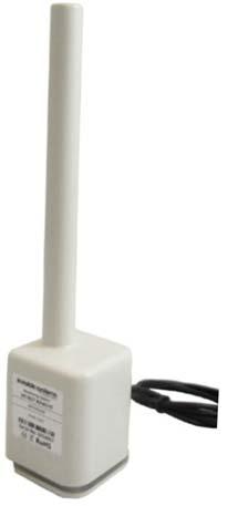
1 Installation Manual Ultra RF Analogue Transmitter QC0168 Manual Ref: QC0168 Version: March


2 System Concept RF Transmitters connect to sensors or meters and send data to the infrastructure internet connected Gateway on site The Gateway stores and transfers the data to the Realtime Online cloud server over a secure mobile cellular connection Realtime Online provides a web based portal of visualisation dashboards, reports, graphs and transmits out tailored automatic reports and notifications in the event of exceptions Version Date Author Changes Tracking v /03/2017 Chris Boddy Invisible Systems Limited Page 2
3 Contents 1. Introduction Installation Fitting Example Testing the circuit Sensor Numbering Locating Sensors Checking operation Dashboard configuration Appendix 1 Part Numbers Invisible Systems Limited Page 3
4 1. Introduction The Analogue transmitter defined in this specification is designed to measure the ma output being generated by the compatible chosen equipment for monitoring. For example, there are numerous analogue devices used in the HVAC controls world. Typically, analogue output devices are used to provide modulating control of valves, dampers, electric motors through variable speed drives and a wide variety of other devices. The most common devices associated with analogue outputs are sequencers, variable speed drives, silicon controlled rectifiers and actuators. After connection of the analogue transmitter in series with these circuits the operational status can be monitored. Commonly the analogue transmitter is used to monitor amps, pressure, water flow, level tanks, and Ph values when attached to the appropriate equipment supplying a analogue output. There are differences with equipment providing an analogue output, some devices have an output with a active voltage where this transmitter can be directly connected and others have a analogue output that needs exciting with a power supply. If this is the case the appropriate power supply would need to be connected in addition to the analogue transmitter to allow operation. The analogue transmitter is available in four different configurations, for compatibility to different applications and equipment: 4 20mA ( ) 0 1 volt ( ) 0 5 volt ( ) 0 10 volt ( ) Features A variety of available radio frequency options Small footprint Automatic data collection and transmission Wireless, range of up to 15km line of sight Battery powered with up to 3 year battery life Technical information Operating frequency 868MHz (Other frequencies available 915 MHz) Operating range up to 15km line of sight Suitable to monitor any device with a analogue output Storage Conditions: 0 C to +50 C Relative Humidity: 25% to 95% Operating Temperature: 0 C to 40 C Applications, any compatible meter/device with a analogue output i.e.: Flow monitoring PH value monitoring Tank Level Monitoring Invisible Systems Limited Page 4
 Red cable + Black cable These connections need to")

5 2. Installation. The connection for the analogue transmitter is as follows; (Must always be connected to the appropriate energised analogue circuit) Red cable + Black cable These connections need to be connected in series with the appropriate circuit as they work on the same principle as an amp meter. See example circuit diagrams below for more information. 2.1 Fitting Example Most Realtime-Online sensors have a unique mounting clip on the battery compartment which allows the sensor to be installed: Mounted with screws through the mounting clip. Care should be taken when mounting and drilling holes in the designated area as the cables present on the inside of enclosures will need to be avoided Invisible Systems Limited Page 5
6 Below shows examples of different circuit diagrams with the 4 20 ma transmitter fitted in series (current loop) within the appropriate circuit. The other transmitters types referred to in this manual are wired in the same way; the 4 20 ma is shown as an example. Diagram 1 Diagram 2 Diagram 3 Invisible Systems Limited Page 6
7 Caution When connecting to this type of solution, the correct safety protocols for site would need to be followed when working on this type of equipment. It is recommended that the associated manual for the equipment being connected to be fimiliarised with prior to commencement of work. 3. Testing the circuit. An appropriate ma meter is required to enable testing of the circuit. As with the transmitter connection the ma meter is required to be fitted within the circuit in series before the transmitter connection. Below shows diagram 3 with a Multimeter connected in series. This allows for the analogue range being delivered by the device to be cross checked with the meter. Invisible Systems Limited Page 7

8 4. Sensor Numbering Each sensor is supplied with a unique serial number marked on the side together with a barcode which is used to identify the sensor on the Realtime Online dashboard. It is vital these numbers are accurately recorded otherwise it will be impossible to identify the sensor in ISL Setup or the server dashboard for the specific site. Note: a sensor number cannot appear more than once on the same site, but can appear on more than one site dashboard. 5. Locating Sensors Realtime Online Sensors use radio frequency communication to a local gateway. The distance between sensors and the gateway can also be very long (up to 15Km line of sight). However, environmental factors such as walls and furniture can reduce this distance considerably so optimal placement of sensors is important. Note; this document does not specifically cover the installation of Gateways which are covered in a separate document, (see index) but the following general guidance is given. When placing sensors, avoid the following: a. Placing the transmitter in metal enclosures such as a distribution boards. b. The transmitters are splash proof and are suitable for installation in outdoor areas, but are not 100% waterproof. Do not install them in positions where they are liable to be submerged. c. Do not install the transmitters close to other RF sources such as alarm systems, door openers or other radio systems. Although the amount of RF energy transmitted by the sensors is very small indeed, there is a possibility that they could interfere with other electrical devices, so they must not be installed close to other devices which could be affected e.g. medical devices or wireless alarm systems. When sitting the gateway, try to ensure the location is approximately equidistant in radio signal terms from all the sensors. Typically, sensors can be expected to pass through 4 5 normal internal walls without difficulty. Invisible Systems Limited Page 8


9 The following illustration shows how sensors which are hidden behind large metal objects like tanks or steel walls may have difficulty in transmitting to the gateway. Possible repeater location Notes Care must be taken when installing this sensor as live electrical circuits are usually within the vicinity. Seek to guidance of a qualified electrician if you are unsure. Battery For safety considerations, all wireless transmitters are transported with the internal battery disconnected. Usually this can be confirmed if the white connector is passing through the base. On first use it is therefore necessary to connect the battery following the steps below: 1. Remove the four screws at the base of the sensor. Then remove the base and the sealing gasket. 2. Carefully insert the small white plug into the PCB socket and ensure the cable passes through the notch to avoid pinching. See diagram below. 3. Replace the sealing gasket, cover and 4 screws. DO NOT OVERTIGHTEN! Invisible Systems Limited Page 9


10 4. Checking operation Following installation of the Pulse transmitter, it is suggested that the operation is checked to ensure the transmitter is being received by the Gateway. Open Ultra RF Gateway Setup This should be located on the desktop of your laptop. On first use, if requested, select the USB lead being used and highlight for use. Name lead connection and select it in drop down list Screen information being displayed. The Screen will show the transmitters it can see in range of the receiver; these can be sorted by sensor type or ID as per preference. Invisible Systems Limited Page 10
11 Each Transmitter will show the following 1. Sensor ID 2. Transmitter Type 3. Battery Voltage 4. Values being received 5. Signal Strength and frequency It is important to check all of this information to confirm that each sensor is being seen by the gateway and at regular intervals in relation to (5). Blue colour dots show direct messages being received and Orange colour dots show messages received via repeaters. Correct setup and operation of Realtime online, will require all the Sensor ID s and Transmitter types in conjunction with the Gateway ID. The RSSI is shown in dbm with a bar chart showing signal strength. This is an important parameter. The table below shows dbm ranges in relation to Signal strength. The range shown above reads 100dBm this is shown in the table as a Marginal signal therefore will need improving either by reviewing the transmitter location, moving the Gateway closer or adding a signal repeater in between transmitter and receiver. Value RSSI Signal RSSI Signal Value dbm Strength dbm Strength Marginal Good Marginal Good Marginal Good Marginal Excellent Marginal Excellent 7 99 Marginal Excellent 8 97 Marginal Excellent 9 95 Marginal Excellent OK Excellent OK Excellent OK Excellent OK Excellent OK Excellent Good Excellent Good Further technical reference and product info can be obtained from associated data sheets Invisible Systems Limited Page 11

12 5. Dashboard configuration Following successful login to Realtime Online with your username and password, create new sensor (System > Sensor Setup > Create New Sensor) Enter Sensor ID number located on the side of the Status Transmitter Name the Senor as required with reference to site requirements for ease of identification. Select Sensor Type = Condition. Select unit = as desired in drop down menu. Select Analog from dropdown. Fill in the analogue formula that relates to the 4 20ma scaling for the device being monitored. Below shows *1, this setting with only show the actual mareading being seen at the transmitter connection. If alerts are needed the delay before alarm can be set. The alert Day/Night Option can be switched on or off by selecting the option. Click Create Sensor Example: Dual Input Status Transmitter When using a dual input status transmitter repeat the setup as above but change the Loop 1 input to Loop 2. Then update sensor. Invisible Systems Limited Page 12
13 6. Appendix 1 Part Numbers. Part Number Item Description Ultra RF Analogue Transmitter 4 20mA Input Ultra RF Analogue Transmitter 0 1 Volt Ultra RF Analogue Transmitter 0 5 Volt Ultra RF Analogue Transmitter 0 10 Volt Invisible Systems Limited Page 13
Installation Manual. Temp Tx-Sensor with Micro switch QC0164. Version: FEB17 1.0
 Installation Manual Temp Tx-Sensor with Micro switch QC0164 Manual Ref: QC0164 Version: FEB17 1.0 System Concept RF Transmitters connect to sensors or meters and send data to the infrastructure internet
Installation Manual. Repeater QC0149. Version: Jan17 1.0
 Installation Manual Repeater QC0149 Manual Ref: QC0149 Version: Jan17 1.0 System Concept RF Transmitters connect to sensors or meters and send data to the infrastructure internet connected Gateway on site
Installation Manual Multi Input Temperature Logger QC0163. Manual Ref: QC0163. Version: FEB17 1.0
 Installation Manual 3999-913-2252 Multi Input Temperature Logger QC0163 Manual Ref: QC0163 Version: FEB17 1.0 System Concept RF Transmitters connect to sensors or meters and send data to the infrastructure
Installation Manual. 3 Phase Wireless Meter QC0142. Version: NOV16 1.0
 Installation Manual 3 Phase Wireless Meter QC0142 Manual Ref: QC0142 Version: NOV16 1.0 System Concept RF Transmitters connect to sensors or meters and send data to the infrastructure internet connected
Installation Manual. Mains Powered Modbus Transmitter QC0150. Version: JAN17 1.0
 Mains Powered Modbus Transmitter QC0150 Manual Ref: QC0150 Version: JAN17 1.0 System Concept RF Transmitters connect to sensors or meters and send data to the infrastructure internet connected Gateway
AW900-SPEC USER S MANUAL
 USER S MANUAL 900 MHz Site Survey Spectrum Analyzer Industrial-grade, long-range wireless Ethernet systems AvaLAN W I R E L E S S User s Manual Thank you for your purchase of the AW900-SPEC Site Survey
HANWELL UTILITY DATA SHEET
 HANWELL UTILITY DATA SHEET HANWELL UTILITY The Hanwell utility range is an innovative monitoring system that measures and records utility usage over time and allows statistical analysis of kilowatts/hrs,
4-20mA, 0-10V and general process measuring bargraph displays
 Page 1 of 6 Digital panel meters Large displays Bargraphs Transmitters 4-20mA, 0-10V process input bargraph displays Display almost any physical variable... The bargraph displays on this page accept most
AW5800-SPEC USER S MANUAL
 USER S MANUAL 5.8 GHz Site Survey Spectrum Analyzer Industrial-grade, long-range wireless Ethernet systems AvaLAN W I R E L E S S User s Manual Thank you for your purchase of the AW5800-SPEC Site Survey
PLUS WGW420 WIRELESS GATEWAY 868MHz
 PLUS WGW420 WIRELESS GATEWAY 868MHz REF.: PA164510210 An easy-to-use system that allows wireless reception and transmission of any process variables that could be transformed into an analogue signal. PLUS
The wireless alternative to expensive cabling...
 The wireless alternative to expensive cabling... ELPRO 105U ISO 9001 Certified New Products... New Solutions The ELPRO 105 range of telemetry modules provide remote monitoring and control by radio or twisted-pair
TeleMET II User s Guide. Cellular Interface & Optional Remote Solar Power Pack
 TeleMET II User s Guide Cellular Interface & Optional Remote Solar Power Pack Copyright 2016 by RainWise, Inc. All rights reserved. No part of this work may be reproduced in any form except by written
Frequently Asked Questions
 Frequently Asked Questions This document provides a non-exhaustive collection of some of the questions frequently asked by our customers. What is your system s wireless range? 1 What are the risks of interference
The wireless alternative to expensive cabling...
 The wireless alternative to expensive cabling... ELPRO 105U Wireless Solutions for Process Applications New Products... New Solutions The ELPRO 105U range of wireless I/O provides a low cost alternative
Yara Water Solution. Installation Guide. Product summary: - Included components - Tools for setup - Installation overview
 Yara Water Solution Installation Guide Product summary: - Included components - Tools for setup - Installation overview Step by step installation guide: - Mounting the Base Station - Preparing the field
The wireless alternative to expensive cabling...
 The wireless alternative to expensive cabling... ELPRO 905U Wireless Solutions for Process Applications New Products... New Solutions The ELPRO 905U range of telemetry modules provide remote monitoring
Thank you choosing the Britpart Tyre Pressure Monitoring System.
 2 Contents Thank you choosing the Britpart Tyre Pressure Monitoring System. This system is an advanced monitoring & alert system of tyre conditions. It monitors tyre pressure and temperature and relays
Wireless sensor system
 Wireless sensor system Internet / Ounet PC in internal network GW Internet connection FIGURE 1 structure of wireless sensor network = Base station = Routing wireless sensor = Wireless sensor General description
I n s ta l l at i o n M a n u a l f o r T E D P r o H o m e T E D P r o L i t e A B C Rev 4.0
 I n s t a l l a t i o n M a n u a l f o r T E D P r o H o m e T E D P r o L i t e A B C Rev 4.0 IMPORTANT: The installation of your TED Pro Home system is a several-step process. The 1st step is the installation
WIRELESS MODBUS GATEWAY WGW410
 WIRELESS MODBUS GATEWAY WGW410 The Tekon Wireless Modbus Gateway WGW410 is specifically designed to meet the most rigorous requirements of operation in the industrial process environments. Due to their
Guide. Installation. Wilson Electronics, Inc. Direct Connection High Power iden Amplifi er 800 MHz Band. Contents:
 Amplifier Installation Guide Direct Connection High Power iden Amplifi er 800 MHz Band Contents: Guarantee and Warranty 1 Before Getting Started / How it Works 3 Installing a Wilson Outside Antenna - In-Vehicle
WIRELESS 868 MHz TEMPERATURE STATION Instruction Manual
 WIRELESS 868 MHz TEMPERATURE STATION Instruction Manual INTRODUCTION: Congratulations on purchasing this fancy 868MHz Temperature Station which displays the time, indoor temperature and indoor humidity,
The wireless alternative to expensive cabling...
 The wireless alternative to expensive cabling... ELPRO 905U Wireless Solutions for Process Applications New Products... New Solutions The ELPRO 905U range of wireless I/O provides a low cost alternative
Proximity Probe Checker PC-100
 Proximity Probe Checker PC-100 User Manual September 2015, Rev. 5.3 Please read carefully this manual before Operating the Proximity Probe Checker PC-100 NORTH Protection Ltd, Member of the NORTH Group
ēko Pro Series System
 ēko Pro Series System FOR ENVIRONMENTAL MONITORING The ACEINNA ēko Pro Series Starter Kit is a wireless agricultural and environmental sensing system for crop monitoring, microclimate studies and environmental
AcuMesh Wireless RS485 Network. User's Manual SOLUTION
 AcuMesh Wireless RS485 Network User's Manual AN SOLUTION ACUMESH - WIRELESS METERING SYSTEM COPYRIGHT 2015 V1.2 This manual may not be altered or reproduced in whole or in part by any means without the
Wireless Outdoor/Indoor Rechargeable Speaker System. User's Manual
 Wireless Outdoor/Indoor Rechargeable Speaker System User's Manual Contents 2 Specifications 3 Product Features 4 Introduction 5 Setting up Setting Up the Transmitter Locating the Transmitter Charging
Featherweight GPS Tracker User s Manual June 16, 2017
 Featherweight GPS Tracker User s Manual June 16, 2017 Hardware Configuration and Installation The dimensions for the board are provided below, in inches. Note that with the antenna installed, the total
I n s t a l l a t i o n M a n u a l. T E D P r o L i t e A B C. f o r. Shop for The Energy Detective products online at: Rev 3.
 Rev 3.5 I n s t a l l a t i o n M a n u a l f o r T E D P r o H o m e T E D P r o L i t e A B C Shop for The Energy Detective products online at: 1.877.766.5412 IMPORTANT: The installation of your TED
Yara Water Solution. Installation Guide. Product summary: - Included components - Tools for setup - Installation overview
 Yara Water Solution Installation Guide Product summary: - Included components - Tools for setup - Installation overview Step by step installation guide: - Mounting the Base Station - Preparing the field
Setup Guide. support.spruceirrigation.com.
 FCC Compliance Statement This device complies with Part 15 of the FCC Rules. Operation is subject to the following two conditions: (1) this device may not cause harmful interference, and (2) this device
Connecting the Radio:
 Connecting the Radio: Step 1: Connect the Cat5 cable from the radio into the RJ-45 jack marked CPE on the POE injector. The POE injector is not weather proof and should be installed indoors. Step 2: Connect
TOP VIEW. 6.75" (171.5mm) Network ID Selector. Input Voltage Selection Jumper 7.285" (185mm) Battery Positive Terminal SIDE VIEW. 6.12" (155.
 Network ID Selector. Input Voltage Selection Jumper 7.285 (185mm) Battery Positive Terminal SIDE VIEW. 6.12 (155.") Installation and Operation Instructions RR2552 Spread Spectrum Repeater TOP VIEW 6.75" (171.5mm) Network ID Selector Ø0.190 (4 PLCS.) Data Link LED 3.5" 4.72" (88.9mm) (119.89mm) Active LED Battery Positive
Installation and Operation Instructions RR2552 Spread Spectrum Repeater TOP VIEW 6.75" (171.5mm) Network ID Selector Ø0.190 (4 PLCS.) Data Link LED 3.5" 4.72" (88.9mm) (119.89mm) Active LED Battery Positive
Remote Site Monitoring
 Remote Site Monitoring FEATURES AT A GLANCE Codan Radio Communications now offers Remote Site Monitoring options that provide live site information, giving you the power to respond intelligently to communications
Wireless Transceiver - Bell & Tone Scheduling Troubleshooting Guide
 Primex XR 72MHz Synchronized Time Solution Wireless Transceiver - Bell & Tone Scheduling Troubleshooting Guide 2018 Primex. All Rights Reserved. The Primex logo is a registered trademark of Primex. All
Planning Guidelines. Lightcloud. Best Practices for Installing Lightcloud
 Best Practices for Installing Lightcloud Planning Guidelines Lightcloud Network Wireless Networking Considerations Wireless Mesh Network Placement of Devices Powering Devices Placing the Gateway Installation
VOLTAGE. User Guide ACCESSORIES. External Sensor DT140. for MicroLog EC600 and EC V ±0.05V ±3% (before calibration)
") External Sensor VOLTAGE DT140 Range: Resolution: Accuracy: Input impedance: Calibration: OV protection: 0-10V ±0.05V ±3% (before calibration) 3MΩ 2 calibration points ±30V ACCESSORIES User Guide for MicroLog
External Sensor VOLTAGE DT140 Range: Resolution: Accuracy: Input impedance: Calibration: OV protection: 0-10V ±0.05V ±3% (before calibration) 3MΩ 2 calibration points ±30V ACCESSORIES User Guide for MicroLog
LMLR-710 (Plug-in type door chime receiver) LMLT-711 (push unit door chime transmitter)
 LMLT-711 (push unit door chime transmitter)") MODEL: LMLR-710 (Plug-in type door chime receiver) LMLT-711 (push unit door chime transmitter) FEATURE: * 67 million self-learning coding RF wireless operation system. No interference with neighbors. *
MODEL: LMLR-710 (Plug-in type door chime receiver) LMLT-711 (push unit door chime transmitter) FEATURE: * 67 million self-learning coding RF wireless operation system. No interference with neighbors. *
Instruction Manual for the Software of ASSAN V2 Series Receiver
 Instruction Manual for the Software of ASSAN V2 Series Receiver I. Setup 1. Double click SETUP to enter the welcome interface and click Next. 2. Enter your name and company name and click Next. 3. Select
Landis+Gyr. S4e MFMM Cellnet User Manual. Bulletin Revision A. DOCUMENT HISTORY Bulletin:
 S4e MFMM Cellnet User Manual Bulletin 051101 Revision A Information in this document is subject to change without notice. No part of this document may be reproduced or transmitted in any form or by any
LAZERPOINT RF WIRELESS DOOR ACTIVATION SYSTEM
 RF TRANSMITTERS & RECEIVERS LAZERPOINT RF WIRELESS DOOR ACTIVATION SYSTEM CM-TXLF SERIES LAZERPOINT RF WIRELESS DOOR ACTIVATION SYSTEM Lazerpoint RF by Camden Door Controls is the industry s most advanced
Table 1. Placing the Sensor in the Sensor Cradle. Step Instruction Illustration
 Table 1. Placing the Sensor in the Sensor Cradle Step Instruction Illustration 1. A. Check "U-shaped" Positioner. The number pointing towards the Sensor (1 or 2) must correspond with the Sensor's size.
AW2400iTR USER S MANUAL 2.4 GHz Indoor Wireless Ethernet Radio
 USER S MANUAL 2.4 GHz Indoor Wireless Ethernet Radio Industrial-grade, long-range wireless Ethernet systems AvaLAN W I R E L E S S Thank you for your purchase of the AW2400iTR Indoor Wireless Ethernet
SYSTEM SENSOR WIRELESS REMOTE INDICATOR PRODUCT SPECIFICATION
 Model name: M200I-RF Introduction: The 200 Series Commercial RF System is designed for use with compatible intelligent fire systems using the System Sensor 200/500 Series CLIP, Enhanced and Advanced communication
Cellular Network Interface (CNI) Models GSM18, GSM20 and CDMA18
 Models GSM18, GSM20 and CDMA18") Cellular Network Interface (CNI) Models GSM18, GSM20 and CDMA18 (Battery-Powered Unit Assemblies with Single- and Dual-Channel Pressure Tracker-II Options) User s Guide Document: 900353 Revision: - September,
Cellular Network Interface (CNI) Models GSM18, GSM20 and CDMA18 (Battery-Powered Unit Assemblies with Single- and Dual-Channel Pressure Tracker-II Options) User s Guide Document: 900353 Revision: - September,
ProLink Radio. 900 MHz SDI-12 Data Radio Scienterra Limited. Version A-0x0C-1-AC 20 October 2009
 ProLink Radio 900 MHz SDI-12 Data Radio Scienterra Limited Version A-0x0C-1-AC 20 October 2009 For sales inquiries please contact: ENVCO Environmental Collective 31 Sandringham Rd Kingsland, Auckland 1024
The CO2 Sensor Calibration Kit
 The CO2 Sensor Kit For use with all BAPI CO 2 Sensors Instruction Manual CO 2 Kit Product Identification and Overview BAPI s CO 2 Sensor Kit is designed to calibrate and verify the operation of all BAPI
Multi-Input Field Unit User Manual
 Rev 1.56 June 2004 Multi- Field Unit User Manual A Division of Adaptive Instruments Corp. 577 Main Street Hudson, MA 01749 U.S.A. TEL: 800-879-6576 978-568-0500 FAX: 978-568-9085 Email: support@accutechinstruments.com
LAZERPOINT RF WIRELESS DOOR ACTIVATION SYSTEM
 DOOR ACTIVATION DEVICES RF TRANSMITTERS & RECEIVERS LAZERPOINT RF WIRELESS DOOR ACTIVATION SYSTEM CM-TXLF SERIES LAZERPOINT RF WIRELESS DOOR ACTIVATION SYSTEM Lazerpoint RF by Camden Door Controls is the
JUMO Wtrans E01. Measuring probe for humidity, temperature, and CO 2 with wireless data transmission. Brief description. Universal Wtrans receiver
 Page 1/13 JUMO Wtrans E01 Measuring probe for humidity, temperature, and CO 2 with wireless data transmission Humidity from 0 to 100 % RH (incl. -40 to +80 C) or CO 2 from 0 to 2000/5000/10000 ppm or Temperature
MLR-1105 (DC battery type door chime receiver) LMLT-711 (push unit door chime transmitter)
 LMLT-711 (push unit door chime transmitter)") MODEL: MLR-1105 (DC battery type door chime receiver) LMLT-711 (push unit door chime transmitter) FEATURE: * 67 million self-learning coding RF wireless operation system. No interference with neighbors.
MODEL: MLR-1105 (DC battery type door chime receiver) LMLT-711 (push unit door chime transmitter) FEATURE: * 67 million self-learning coding RF wireless operation system. No interference with neighbors.
Radio Link Starter Kit
 Radio Link Starter Kit Installation Manual BARTLETT Instrument Co. 1032 Avenue H Fort Madison, IA 52627 319-372-8366 www.bartinst.com Table of Contents Radio Link Starter Kit Manual... 3 System Requirements...
IT-24 RigExpert. 2.4 GHz ISM Band Universal Tester. User s manual
 IT-24 RigExpert 2.4 GHz ISM Band Universal Tester User s manual Table of contents 1. Description 2. Specifications 3. Using the tester 3.1. Before you start 3.2. Turning the tester on and off 3.3. Main
EMWIN User Training. For Colorado Front Range. September, 2007
 EMWIN User Training For Colorado Front Range September, 2007 Agenda 1 p.m. Getting Started SOME ASSEMBLY REQUIRED Antenna Radio equipment RealEMWIN Software installation 2:30 p.m. Basic features of RealEMWIN
Rev RF Service Tool Operator s Guide
 026-1703 Rev 0 7-23-01 RF Service Tool Operator s Guide 1640 Airport Road, Suite 104 Kennesaw, GA 31044 Phone: (770) 425-2724 Fax: (770) 425-9319 ALL RIGHTS RESERVED. The information contained in this
ARUBA AS-100 WIRELESS SENSOR
 Multivendor, Remote Management for Aruba Bluetooth Low Energy Beacons Aruba Mobile Engagement enables venues to engage with visitors mobile devices using Aruba Beacons powered by Bluetooth Low Energy (BLE)
WIRELESS Energy Monitor - Smart Meter
 Energy saving made simple MONITOR CONTROL SAVE WIRELESS Energy Monitor - Smart Meter Monitors your electricity use and cost in real time Instruction Manual EW4500 IMPORTANT Please retain your Instruction
AW900xTR USER S MANUAL 900 MHz Outdoor Wireless Ethernet Radio
 USER S MANUAL 900 MHz Outdoor Wireless Ethernet Radio Industrial-grade, long-range wireless Ethernet systems Thank you for your purchase of the AW900xTR Outdoor Wireless Ethernet Radio. The AW900xTR includes:
GPSR400 Quick Start Guide
 GPSR400 Quick Start Guide Rev. 6 Introduction Microlab s digital GPS repeater system can be used for cellular communications UTC synchronization for locations where the GPS signals are not readily available.
PHALCON 2000 Installation Guide
 PHALCON 2000 Installation Guide PHAROS MARINE 1999 The copyright in this document is vested in AB Pharos Marine Ltd. and the document is issued in confidence for the purpose only for which it is supplied.
GS Strain gauge reader/ transmitter. GS series of wireless industrial sensors. Features: General Description: Applications:
 GS series of wireless industrial sensors Strain gauge reader/ transmitter Features: Input: strain gauge Wheatstone bridge: 300ohms to 10kohms. Typical: 1000 ohms. Standard input range: up to 2mV/V full
SCOUT Mobile User Guide 3.0
 SCOUT Mobile User Guide 3.0 Android Guide 3864 - SCOUT February 2017 SCOUT Mobile Table of Contents Supported Devices...1 Multiple Manufacturers...1 The Three Tabs of SCOUT TM Mobile 3.0...1 SCOUT...1
DM 800H Twin Handheld UHF System (863.0Mhz-865.0Mhz)
") DM 800H Twin Handheld UHF System (863.0Mhz-865.0Mhz) User Manual Order code: MIC78 Safety advice WARNING FOR YOUR OWN SAFETY, PLEASE READ THIS USER MANUAL CAREFULLY BEFORE YOUR INITIAL START-UP! Before
DM 800H Twin Handheld UHF System (863.0Mhz-865.0Mhz) User Manual Order code: MIC78 Safety advice WARNING FOR YOUR OWN SAFETY, PLEASE READ THIS USER MANUAL CAREFULLY BEFORE YOUR INITIAL START-UP! Before
88950-A Series A Series INSTRUCTION MANUAL
 88950-A Series 98950-A Series INSTRUCTION MANUAL Specifications And Leading Particulars The 88950 and 98950 series Wattmeter is designed to work with any Coaxial Dynamics line section and the appropriate
Copyright Teletronics International, Inc. Patent Pending
 Copyright 2003 By Teletronics International, Inc. Patent Pending FCC NOTICES Electronic Emission Notice: This device complies with Part 15 of the FCC rules. Operation is subject to the following two conditions:
POTENTIAL APPLICATIONS OF TEKON ELECTRONICS PRODUCTS
 02.V07.2017 TEKON ELECTRONICS Tekon Electronics is an European brand, specialized in the manufacture and development of innovative wireless sensors technology. It is a business unit of Bresimar Automação,
SYSTEM SENSOR WIRELESS REPEATER PRODUCT SPECIFICATION
 Model name: M200F-RF Introduction: The 200 Series Commercial RF System is designed for use with compatible intelligent fire systems using the System Sensor 200/500 Series CLIP, Enhanced and Advanced communication
MGL Avionics Garrecht VT-0102 mode-s transponder Interface installation manual
 MGL Avionics Garrecht VT-0102 mode-s transponder Interface installation manual Document date: September 2012 This document should be read in conjunction with the Garrecht VT-0102 installation manual General
Technical description of the fuel tank sensor "Escort TD-500"
 Technical description of the fuel tank sensor "Escort TD-500" Kazan, 2016 1 Table of contents 1. General info..3 2. Technical characteristic.. 3 3. Operating mode. 3 3.1. Mode RS-485 3 3.2. Frequency mode
JUMO Wtrans probe RTD temperature probe with wireless transmission of the measured values
 JUMO Wtrans probe RTD temperature probe with wireless transmission of the measured values k For measured temperatures from -30... +260 C or -200... +600 C k For mobile or stationary temperature measurement
Specification Sym Notes Minimum Typical Maximum Units 900 MHz Operating Frequency Range MHz
 900 MHz FHSS DNT90/Ethernet Gateway Optional 128-Bit AES Encryption Point-to-point, Point-to-multipoint or Store and Forward Operation 158 mw EIRP 900 MHz Transmitter Power 10/100Base-T Auto-sensing Ethernet
DJA3000. Cellular Communication Jammer. Installation and Operations Manual. Series DJA3000. Description: Cellular Communication Jammer
 DJA3000 Cellular Communication Jammer Installation and Operations Manual Series DJA3000 Description: Cellular Communication Jammer Models: DJA3040 and DJA3120 Series DJA3000 up to 4 Bands Thank you for
Rosemount 753R Remote Web Based Monitoring Indicator
 Rosemount 753R Remote Web Based Monitoring Indicator Product Discontinued February 2010 Start Overview Rosemount 753R with Integral 3051S Pressure Transmitter Rosemount 753R with Remote Mounted HART Transmitter
USER MANUAL. Sens it SENS IT 2.4
 USER MANUAL www.sensit.io Sens it SENS IT 2.4 SUMMARY SAFETY INSTRUCTIONS 4 I. CONTENT OF THE PACK 4 II. PRESENTATION 5 III. HOW TO START 8 IV. TECHNICAL SPECIFICATIONS 9 V. WARNING STATEMENTS 10 VI. CREDITS
CORD-Pager USER MANUAL
 CORD-Pager USER MANUAL ROHRBACK COSASCO SYSTEMS, INC. 11841 E. Smith Avenue Santa Fe Springs, CA 90670 Tel: (562) 949-0123 (800) 635-6898 Fax: (562) 949-3065 TABLE OF CONTENTS Chapter 1 - Introduction...
Commercial Vehicle Productivity and Security. Antenna Configuration. External Antenna Installation (model 6650H only) Contigo 6650H/6651H Beacon
 Contigo 6650H/6651H Beacon") Commercial Vehicle Productivity and Security The 6650H/6651H is a versatile and economical GPS tracking beacon designed for fleet management needs in all commercial vehicles. The H designation in the model
Commercial Vehicle Productivity and Security The 6650H/6651H is a versatile and economical GPS tracking beacon designed for fleet management needs in all commercial vehicles. The H designation in the model
Conductivity Transmitter
 Conductivity Transmitter Programmable outputs: two transistor and single or dual analog 4-20 ma Removable backlighted display Universal process connection Type can be combined with... Three cell constants
TT-208. User s Manual. 300Mps 5.8 GHz. IP Camera Wireless Transmission Kit
 TT-208 300Mps 5.8 GHz IP Camera Wireless Transmission Kit User s Manual V1.0 02 / 2014 Welcome Thank you for purchasing the TT-208 Wireless Transmission Kit for IP Cameras. This user s manual is designed
P2P 2 YEAR PL-VDIO-05. Smartphone Connect IP VIDEO DOOR PHONE QUICK START GUIDE 7 VIDEO DOOR PHONE SYSTEM WITH SMARTPHONE CONNECT
 PL-VDIO-05 IP VIDEO DOOR PHONE QUICK START GUIDE Smartphone Connect 2 YEAR RR T SERVICES WA P2P Y Receive calls, remote monitor and remote unlock with your smart phone AN 7 VIDEO DOOR PHONE SYSTEM WITH
WATER MADE EASY MARINE ENERGY MUNICIPAL INDUSTRIAL
 MicroChem Water Analysis System The MicroChem is a versatile multi-parameter instrument capable of being configured as a transmitter or PID controller. Specifically designed for drinking and wastewater
TRMC-19 GSM/GPRS DATALOGGER. Applications. Product description. Measure and remote monitoring
 TRMC-19 GSM/GPRS DATALOGGER The TRMC-19 is a datalogger/dataconcentrator of measures GSM/GPRS radio or wire. This device fulfills the most demanding requirements and will help you to create an effective,
Lesson 3: Arduino. Goals
 Introduction: This project introduces you to the wonderful world of Arduino and how to program physical devices. In this lesson you will learn how to write code and make an LED flash. Goals 1 - Get to
Instruction also available on
 TERA Radon Program EN TCR3 Central Unit Technical Specifications & Operation Manual v.2 2016 Table of Contents 1 Introduction...2 2 Description and Utilization...2 3 Scope of Delivery...4 4 Product Specification...5
Connecting Mains Electrical Power
 Tide Level Monitoring Instrumentation The following documentation details the electrical installation for the tide level monitoring instrumentation and also a summary of the logger configurations required
200 RTH OFF ON IN OUT ALARM RESET
 200 RTH OFF ON IN OUT ALARM RESET EN OWNER S MANU AL www.auraton.pl 2 3 Thank you for purchasing the modern temperature controller based on an advanced microprocessor. AURATON 200 RTH LCD FrostGuard function:
CAST Application User Guide
 CAST Application User Guide for DX900+ Electromagnetic Multilog Sensor U.S. Patent No. 7,369,458. UK 2 414 077. Patents Pending 17-630-01-rev.b 05/24/17 1 Copyright 2017 Airmar Technology Corp. All rights
Wireless Room Temperature and Humidity Transmitter (Units without Temperature Setpoint or Override) Installation and Operating Instructions
 Installation and Operating Instructions") Wireless Temperature and Humidity Overview and Indentification The Wireless Temperature and Humidity measures the room temperature and Relative Humidity and transmits the data at 418MHz or 433MHz RF to
Wireless Temperature and Humidity Overview and Indentification The Wireless Temperature and Humidity measures the room temperature and Relative Humidity and transmits the data at 418MHz or 433MHz RF to
Wireless Temp/Setpoint & Override Room Transmitter
 Overview The BAPI Wireless Combination Transmitter measures the room temperature and relative humidity and transmits the data at 418MHz or 433MHz RF to a receiver. Temperature setpoint and override button
VT8300 Series Installation Guide 24 Vac Low Voltage
 VT00 Series Installation Guide Low Voltage mercial and Hotel/Lodging HVAC Fan Coil Applications CONTENTS Installation Terminal Identification & Function Terminal identification Wiring Typical Applications
RM24100A. Introduction. 1 Features. 2.4GHz 100mW RS232 / RS485 / RS422 DSSS Radio Modem (IEEE compliant) Operating Manual English 1.
 Operating Manual English 1.") RM24100A 2.4GHz 100mW RS232 / RS485 / RS422 DSSS Radio Modem (IEEE 802.15.4 compliant) Operating Manual English 1.03 Introduction The RM24100A radio modem acts as a wireless serial cable replacement and
RM24100A 2.4GHz 100mW RS232 / RS485 / RS422 DSSS Radio Modem (IEEE 802.15.4 compliant) Operating Manual English 1.03 Introduction The RM24100A radio modem acts as a wireless serial cable replacement and
The Instructions should be read, prior to commencing the installation, failure to follow these instructions will void your warranty.
 Low Voltage System The Platinum Low Voltage lighting system can power up to 120 candle pods depending on the length of cables used during the installation this can reduce the number of pods to 24 per outlet
Group 4. Michael Cooke David Griffen Whitney Keith
 Group 4 Michael Cooke David Griffen Whitney Keith Edward Romero (EE) (CpE) (EE) (EE/CpE) One television s audio is broadcasted within a restaurant/gymnasium leaving all other televisions muted. Customers
Universal Voice Coil and 70 Volt Door Speaker V / V
 PagePac by ISSUE 2 Universal Voice Coil and 70 Volt Door Speaker V-5330120 / V-5330230 Installation Manual 947179 Your PagePac Door Speaker Note: The Door Phone Controller and PagePac 6 systems require
Disclaimers. Important Notice
 Disclaimers Disclaimers Important Notice Copyright SolarEdge Inc. All rights reserved. No part of this document may be reproduced, stored in a retrieval system, or transmitted, in any form or by any means,
DataCAD 18 Softlock. Universal Installer. Installation. Evaluation
 DataCAD 18 Softlock DataCAD 18 uses a software-based license management option, referred to as a softlock, in lieu of the hardware-based USB license key, or hardlock used by older versions. Each DataCAD
LIGHTING KIT SEAMAID COLOR FOR ABOVE GROUND SWIMMING-POOL &
 > Installation guide You just bought the Lighting kit SeaMAID color from the SeaMAID range. Thank you for your trust. Follow this guide and the online video for an easy and quick installation. LIGHTING
ATOMIC WALL CLOCK with REMOTE TEMPERATURE SENSOR Model CL Instruction Manual
 ATOMIC WALL CLOCK with REMOTE TEMPERATURE SENSOR Model CL030027 Instruction Manual Congratulations on purchasing your ATOMIC CLOCK with REMOTE TEMPERATURE SENSOR. Please read these instructions carefully
Wireless Temperature Sensor
 The Leader in Low-Cost, Remote Monitoring Solutions Wireless Temperature Sensor General Description The Wireless Temperature Sensor uses a type NTC thermistor to measure temperature. Features Accurate
Wireless Temperature Sensor with Probe
 The Leader in Low-Cost, Remote Monitoring Solutions Wireless Temperature Sensor with Probe TEMPERATURE 3 FOOT PROBE General Description The Wireless Temperature Sensor with Probe uses a type NTC thermistor
The Leading Enterprise Internet of Things Solution. Wireless Pulse Counter - Single Input SINGLE-INPUT PULSE COUNTER. General Description
 by The Leading Enterprise Internet of Things Solution SINGLE-INPUT PULSE COUNTER Wireless Pulse Counter - Single Input General Description The ALTA wireless pulse counter can be connected to the pulse