Everything You Always Wanted to Know About Optical Networking But Were Afraid to Ask. Richard A Steenbergen Updated: May 1, 2017
|
|
|
- Bethanie Owens
- 5 years ago
- Views:
Transcription
1 Everything You Always Wanted to Know About Optical Networking But Were Afraid to Ask Richard A Steenbergen <ras@turkbergen.com> Updated: May 1,
2 Purpose of This Tutorial Why give a talk about optical networking? The Internet as an industry is largely based around fiber. Yet many router jockeys don t get enough exposure to it. This leads to a wide variety of confusion, misconceptions, and errors when working with fiber optic networks. Will this presentation make me an optical engineer? Maybe, but just remember, I omitted almost all the math. J The purpose of this tutorial is to touch on a little bit of every topic, from the mundane to the advanced and unusual. But it helps to have a basic understanding of how and why things work, even if you aren t designing fiber networks. 2
3 The Basics of Fiber Optic Transmission 3
4 What is Fiber, and Why Do We Use It? Fiber is ultimately just a waveguide for light. Basically: light that goes in one end, comes out the other end. Most commonly made of glass/silica, but can also be plastic. So why do we use fiber in the first place? Very low-cost to produce (silica is cheap). Extremely light (relative to copper), flexible material. Carries tremendous amounts of information (20 Tbps+ today). Can easily carry large numbers of completely independent signals over the same fiber strand, without interference. Can carry signals thousands of kilometers without regeneration Technology continues to radically improve what we can do with our existing fiber infrastructure, without digging or disruption. 4
5 Hold It Down Like I m Giving Lessons in Physics A quick flashback to High School physics class: Light propagating through a vacuum is (theoretically) the maximum speed at which anything in the universe can travel. That speed is 299,792,458 meters per second, otherwise written as c. For doing shorthand math, you can round this up to 300,000 km/s. But when light passes through materials that aren t a perfect vacuum, it actually propagates much slower than this. The speed of light in any particular material is expressed as a ratio relative to c, known as that material s refractive index. Example: Water has a refractive index of 1.33, or 1.33x slower than c. And when light tries to pass from one medium to another with a different index of refraction, a reflection can occur instead. This is why you will see a reflection when you look up from under water. 5

6 Fiber Works by Total Internal Reflection Fiber optic cables are internally composed of two layers. A core, surrounded by a different material known as the cladding. The cladding always has a higher index of refraction than the core. When the light tries to pass from the core to the cladding, and the angle is correct, it is reflected back into the core. 6

7 Demonstration Using a Laser Pointer 7

8 The Inside of a Common Fiber Cable 8
9 How Do We Actually Use The Fiber? The vast majority of deployed fiber optic systems operate as duplex, or as a fiber pair. One strand is used to transmit a signal, the other to receive one. This results in the simplest and cheapest optical components. And usually holds true whenever the fiber is relatively cheap. But fiber is perfectly capable of carrying many signals, in both directions, over a single strand. It just requires more expensive optical components to do so. Which is generally reserved for when the fiber is expensive. As with most things in business, cost is a deciding factor behind the vast majority of the technology choices we make. 9
10 What Do We Actually Send Over Fiber? Our digital signals must be encoded into analog pulses of light The simplest (and cheapest) method is known as IM-DD. Which stands for Intensity Modulation with Direct Detection. The most common version of which is NRZ, or Non-Return to Zero. Which is really just a fancy way of saying bright for a 1, dim for a 0. This modulation (called baud ) can happen billions of times/sec. The receiving end sees these flashes, and turns it back into 1s and 0s. This technique was used for essentially all optical signals up to 10Gbps. Beyond 10GBaud, this technique gets increasing hard to scale. Today we barely squeak out 25GBaud, with FEC, for short reach links. But better than NRZ systems are becoming more pervasive. QPSK 16QAM is the basis for most long-haul links today. PAM4 (Pulse Amplitude Modulation 4) is becoming viable for QSFP28 DWDM optics, and will be used in 400GE client optics. 10


11 What We Transmit Over Fiber 11
12 The Most Basic Distinction in Fiber: Multi-Mode vs Single Mode 12
13 Multi-Mode Fiber (MMF) Specifically designed for use with cheaper light sources. Has an extremely wide core, allowing the use of less precisely focused, aimed, and calibrated light sources. But this comes at the expensive of long-distance reach. Fiber is so named because it allows multiple modes of light to propagate. Modal dispersion typically limit distances to tens to hundreds of meters. Types of Multi-Mode OM1/OM2 aka FDDI grade : found with orange fiber jackets. OM1 has a 62.5 micron (μm) core, OM2 has a 50μm core. Originally designed for 100M/1310nm signals, starts to fail at 10G speeds. OM3/OM4 aka laser optimized : found with aqua fiber jackets. Specifically designed for modern 850nm short reach laser sources. Supports 10G signals at much longer distances ( m, vs 26m on OM1). Required for 40G/100G signals (which are really 10G/25G signals), m. 13
14 Single Mode Fiber (SMF) The fiber used for high bandwidths, and long distances. Has a much smaller core size, between 8-10 microns (μm). No inherent distance limitations caused by modal dispersion Typically supports distances of ~80km without amplification. With amplification, can transmit a signal several thousand kilometers. SMF has an even broader array of types than MMF. Also has OS1 and OS2, but they re packaging, not fiber type. OS1 tight buffered for indoor use, OS2 loose to be blown into ducts. Classic SMF can be called SMF-28 (a Corning product name) But it comes in many different formulations of Low Water Peak Fiber (LWPF), Dispersion Shifted Fiber (DSF), Non-Zero Dispersion Shifted Fiber (NZDSF), Bend Insensitive Fiber, etc. 14

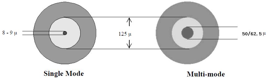
15 Single Mode vs Multi-Mode Fiber 15
16 Basic Optical Networking Terms and Concepts 16
17 Optical Power What is optical power? Quite simply, the brightness (or intensity ) of light. As light travels through fiber, some energy is lost. It can be absorbed by glass particles, and converted into heat; Or scattered by microscopic imperfections in the fiber. This loss of intensity is called attenuation. We typically measure optical power in Decibels A decibel (db, 1/10 th of a Bel) is a logarithmic-scale unit expressing the relationship between two values. The decibel is a dimensionless-unit, meaning it does not express an actual physical measurement on its own. 17
18 Optical Power and the Decibel A decibel is a logarithmic ratio between two values -10dB is 1/10 th the signal, -20dB is 1/100 th the signal, etc. Another easy one: +3dB is double -3dB is half. But remember, this doesn t tell you double of what? To express an absolute value, we need a reference. In optical networking, this is known as a dbm. That is, a decibel relative to 1 milliwatt (mw) of power. 0 dbm is 1 mw, 3 dbm is 2 mw, -3 dbm is 0.5mW, etc. So what does this make 0mW? Negative Infinity dbm. Confusion between db and dbm is probably the single biggest mistake made in optical networking! 18
19 Optical Power and the Decibel Why do we measure light with the Decibel? Light, like sound, follows the inverse square law. The signal is inversely proportional to the distance squared. A signal travels distance X and loses half of its intensity. The signal travels another distance X and loses another half. After 2X only 25% remains, after 3X only 12.5% remains. Using a logarithmic scale simplifies the calculations. A 3dB change is approximately half/double the original signal. In the example above, there is a 3dB loss per distance X. At distance 2X there is 6dB of loss, at distance 3X it is 9dB. This allows us to use elementary school addition/subtraction when measuring gains/losses, which is easier on the humans. 19
20 Decibel to Power Conversion Table (loss) 20
21 Dispersion Dispersion simply means to spread out. In optical networking, this results in signal degradation. As the signal is dispersed, it is no longer distinguishable as individual pulses at the receiver. 21

22 Chromatic Dispersion (CMD) Different frequencies propagate through a non-vacuum at different speeds. This is how optical prisms work. The wider your signal linewidth, the more CMD affects it. The faster your baud rate, the more CMD affects it. So for every doubling of baud rate, CMD increases by 4. 22

23 Polarization Mode Dispersion (PMD) Caused by imperfections in the shape of the fiber. Not perfectly cylindrical fiber causes one polarization of light to propagate faster than the other. The difference in arrival time between the polarizations is called Differential Group Delay (DGD). 23
24 Fiber Optic Transmission Bands There are several frequency windows available 850nm The First Window Highest attenuation, only used for short reach applications today. 1310nm The Second Window (O-band) The point of zero dispersion on classic SMF, but high attenuation. Primarily used for medium-reach applications (~10km) today. 1550nm Third Window (C-band) Stands for conventional band, covers 1525nm 1565nm. Has the lowest rate of attenuation over SMF. Used for almost all long-reach and DWDM applications today. Fourth Window (L-band) Stands for long band, covers 1570nm 1610nm. 24

25 Fiber Optic Transmission Bands 25
26 Optical Signal to Noise Ratio (OSNR) Modern high-bandwidth systems are often more limited by OSNR than any other optical parameter. 26
27 Wave Division Multiplexing 27
28 Wave Division Multiplexing (WDM) What is Wave Division Multiplexing (WDM)? We know that light comes in many different colors. What we perceive as white is actually just a mix of many wavelengths. These different colors can be combined on the same fiber. The goal is to put multiple signals on the same fiber without interference ( ships in the night ), thus increasing capacity. 28

29 Wave Division Multiplexing Channels 29

30 Coarse Wave Division Multiplexing CWDM is loosely used to mean anything not DWDM One popular meaning is 8 channels with 20nm spacing. Centered on 1470 / 1490 / 1510 / 1530 / 1550 / 1570 / 1590 / 1610 With Low Water Peak fiber, another 10 channels are possible Centered on 1270/1290/1310/1330/1350/1370/1390/1410/1430/1450. Can also be used to refer to a simple 1310/1550nm mux. 30
31 Dense Wave Division Multiplexing So what does that make Dense WDM (DWDM)? Defined by the ITU-T G as a grid of specific channels. Within C-band, the follow channel sizes are common: 200GHz 1.6nm spacing, channels 100GHz 0.8nm spacing, channels 50GHz 0.4nm spacing, channels 25GHz 0.2nm spacing, channels A rough guideline to the technology: 200GHz is 2000-era old tech, rarely seen in production any more. 100GHz is still quite common for metro DWDM tuned pluggables. 50GHz is common for commercial, long-haul, and 100G systems. 25GHz was used briefly for high-density 10G systems, before the move coherent 100G systems shifted back to 50GHz. Modern systems are flexible, in 12.5GHz increments or smaller. 31
32 What Are The Advantages to Each? CWDM Cheaper, less precise lasers can be used. DWDM The actual signal in a CWDM system isn t really any wider. But the wide channel allows for large temperature variations. Cheaper, uncooled lasers can more easily stay within the window. Far more channels are possible within the same fiber. 160 channels (at 25GHz) in 32nm of spectrum, vs. 8ch in 160nm. Can stay completely within the C-band Where attenuation and dispersion are far lower that other bands. Where simple Erbium Doped Amplifiers (EDFAs) work. But can also be duplicated within the L-band. 32

33 CWDM vs. DWDM Relative Channel Sizes Peak 13nm wide 20nm wide CWDM channel 33
34 Other Uses of Wave Division Multiplexing But other forms of WDM can be used as well The classic 1310/1550 muxes. 4-lane Grey Optics New high speed interfaces often start using multiple WDM lanes. Cheaper to implement, or supports older fiber technology. 10GE had 10GBASE-LX4 (4x 2.5G channels, rather than 1x 10G) 40GE has LR4 (4x 10G, 1270nm / 1290nm / 1310nm / 1330nm) 100GE has LR4 (4x 25G, 1295nm / 1300nm / 1305nm / 1310nm) Single Strand Optics (BX bidirectional standards) E.g / 1490nm mux integrated into a pluggable transceiver. 34

35 DWDM Channel Terminology 35
36 WDM Networking Components 36

37 WDM Mux/Demux A simple, passive (unpowered) device, which combines/splits multiple colors of light to/from a single common fiber. Short for multiplexer, sometimes called a filter, or prism. A filter is how it actually works, by filtering specific colors. But people conceptually understand that a prism splits light into its various component frequencies. A complete system requires both a mux and a demux, for the TX and RX operation. Often sold as a single package containing both units, for simplicity (and use on duplex fiber). 37
38 The Optical Add/Drop Multiplexer (OADM) Selectively Adds and Drops certain WDM channels, while passing other channels through without disruption. While muxes often used at major end-points to break out all channels, OADMs are often used at mid-points within rings. A well-constructed OADM ring can reach any other node in the ring, potentially reusing some wavelengths multiple times on different portions of the ring. Also an entirely passive and unpowered device. 38
 An etched fiber core, which causes certain frequencies to be reflected.")

39 Passive Optical Filter Technology Passive filters (Mux/OADM) can be build in several ways Thin Film Filter (TFF) Typically used for low channel counts. FBG (Fiber Bragg Grating) An etched fiber core, which causes certain frequencies to be reflected. AWG (Arrayed Waveguide Grating) Typically used for high channel counts. Essentially a very fancy interferometer. Cheapest and lowest IL, but not flat-top. Lowest loss versions have specific temperature constraints. Most common versions are AAWG (Athermal AWG) today. 39

40 Reconfigurable OADM (ROADM) A ROADM is a software reconfigurable OADM Often capable of building many different degrees. 2-degree is the simplest OADM style, east/west and add/drop 4-degree, 8-degree, and 20-degree are also common designs. 40

41 The Evolution of the ROADM Basic ROADM Reconfigurable, but add/drop still goes to a standard fixed mux. Colorless ROADM Eliminates the need to map specific frequencies to specific ports. CDC ROADM Colorless Any channel can be add/dropped on any port. Specific frequencies must be connected to specific ports. The network must be recabled in order to change or move frequencies. But still limited to muxing in one direction at a time. Directionless Any channel can be sent to any direction. Contentionless The same channel can be reused on different directions without causing internal contention in the ROADM. 41
42 Modern Networking and the CDC ROADM The goal is to move optical channels entirely in software. Transponders can be reallocated onto different physical paths as traffic patterns change (due to time-of-day changes, or during fiber cuts), potentially increasing efficiency and reducing costs. Eliminates the need to physically move cables to reconfigure. Allows dynamic bandwidth allocation at an optical level. Potentially the entire process could be automated. IETF pushing for vendor interoperability, and signaling via mechanisms like PCEP (Path Computation Element Protocol). Routers could request additional bandwidth from a pool of underlying transponders on demand, based on real-time traffic requirements. 42


43 What Goes Into a Modern CDC ROADM 43

44 DWDM Superchannels What if we want performance a single carrier can t deliver? Superchannels pack multiple carriers together in a single channel, enabling more bandwidth, longer reach, and cheaper components. Often you can pack the carriers together tighter than if you were using standard channels too, adding spectral efficiency. In this example, we deliver 1 Tbps using existing technology. 44


45 The Evolution of DWDM Channels 45
46 Optical Amplification 46

47 Optical Amplifiers Optical amplifiers increase the intensity of a signal Purely optical way to extend signal reach, no regeneration. There are different types, for different frequencies of light. Different designs, for different positions within the span. Booster Amplifiers are designed for high total output powers. Pre-Amplifiers are designed for low input powers with minimal noise. Inline Amplifiers strike a balance between the two. 47
48 Erbium Doped Fiber Amplifier (EDFA) The most basic/common fiber amplification system. In an EDFA, a piece of fiber is doped with Erbium ions. Another laser (980/1480nm) is pumped in via a coupler. Pump laser puts Erbium electrons into higher energy state. 1550nm photons cause the Erbium electrons to decay to their ground state, and emit a clone of the original photon. 48
49 EDFA Noise So why can t we use this to boost a signal forever? In addition to the intended boosting of signal, EDFAs also generate noise ( Amplified Spontaneous Emission, ASE). Whenever an excited Erbium electron fails to encounter a good photon within ~10ms, it falls back to its ground state spontaneously, emitting noise photons. Once generated, this noise is indistinguishable from the original signal. After enough hops, the noise ruins the original signal. 49
50 EDFA Noise Why Input Power Matters OSNR(dB) Following Cascaded EDFAs, at Various Input Power Levels Optical Signal to Noise Ratio (OSNR) in db EDFA Hops -5 dbm -10 dbm -15 dbm -20 dbm -25 dbm 50

51 Raman Amplification The other major optical amplifier type is Raman. Works on a principal of Stimulated Raman Scattering. Requires very high power pump lasers, long gain mediums. EDFAs used lumped design, gain media of 1-20 meters. Raman usually use distributed design, gain medium 20+ km. 51

52 EDFA Only Amplification 52

53 Hybrid EDFA + Raman Amplification 53
54 Hybrid EDFA + Raman Performance Adding Raman extends EDFA reach significantly! In this example (21dB OSNR): from 7 hops to 20 hops At 100km/each, we go from only 700km to doing 2000km. 54
55 Amplifiers and Power Balance Amplifiers introduce some of their own unique issues Amplifier gain is often varies significantly across frequencies Gain Flattening Filters try to compensate for this property. Typical gain variations between channels ( ripple ) are still < 1dB. Unbalanced channel power causes OSNR penalties Even small power variations can add up after several hops. Dynamic Gain Equalization ( DGE ) is required periodically. ROADMs are often used in this role, to balance every channel. 55
56 Amplifiers and Total System Power Amplifiers also have limits on their total system power Both what they can output, and what they can take as input. And the total input power changes as you add channels. A single channel at +0 dbm is only 1mW of input power. 40 DWDM channels at +0 dbm/each is 40mW, or +16dBm of power. If your amplifier s maximum input power is -6dBm, and you run 40 DWDM channels through it, each channel must be below -22dBm. Failing to plan for this can cause problems as you add channels. The total input power also changes as you lose channels. Imagine power fails to a POP, and many channels are knocked offline. Suddenly the total system power has changed significantly. A good EDFA needs to constantly monitor and adjust power levels. The best EDFAs will communicate with others on the line system. 56
57 Other Optical Networking Concepts 57

58 Optical Switches Optical Switches Let you direct light between ports, without doing O-E-O conversion. Built with an array of tiny mirrors, which can be moved electrically. Allows you to connect two fibers together optically in software. Becoming popular in optical crossconnect and fiber protection roles. 58


59 Wavelength Selective Switch (WSS) Lets you route an individual wavelength across ports The WSS is a key component inside of a ROADM. First generation WSS used 3D MEMS optical switches. Modern WSS use Liquid Crystal on Silicon (LCoS). 59
60 Circulator A component typically not seen by the end user. But frequently used inside other popular components. Bragg grating based components, like OADMs and small muxes. Dispersion compensation spools, amplifiers, etc. Very useful when building single-strand bidirectional systems too. A circulator has 3 fiber ports. Light coming in port 1 goes out port 2. Light coming in port 2 goes out port 3. 60
61 Splitters and Optical Taps Do exactly what they sound like they do, split a signal. Common examples are: A 50/50 Splitter Often used for simple optical protection. Split your signal in half and send down two different fiber paths. Use an optical switch with power monitoring capabilities on the receiver, have it automatically pick from the strongest signal. If the signal on one fiber drops, it switches to the other fiber. A 99/1 or 98/2 Splitter Often used for Optical Performance Monitoring. Tap a small % of the signal, and run it to a spectrum analyzer. 61
62 Forward Error Correction FEC adds extra/redundant information to the transmission, so the receiver can computationally recover from any errors. In practice, FEC works by lowering the required OSNR, which can help an otherwise unusable signal function normally. Using clever math, padding a Gbps signal to 11Gbps (7% overhead) can extend a signal from 80km to 120km or beyond. This can really matter when upgrading older DWDM systems. Since it usually isn t practical to move amp sites closer on a live system. FEC has evolved significantly as well. 1 st Gen RS-FEC 6% overhead for ~6dB of net coding gain. 2 nd Gen - EFEC 7% overhead for ~8-9dB of net coding gain. 3 rd Gen SD-FEC 20-25% overhead for 10-11dB coding gain. It might not seem worth it, but a 1-2dB gain in OSNR can hugely increase optical reach. FEC is key to many standards like 100GBASE-SR4 as well. 62
63 The Benefits of Forward Error Correction 63

64 OTN Digital Wrapper Technology (G.709) OTN stands for Optical Transport Network Replacement for SONET/SDH, with support for optical networking. A standard for the generic transport of any protocol across a common optical network, with TDM mux/demux capabilities. Implemented as a wrapper around other protocols. Why is this needed? Pure optical channels only make sense for high-speed protocols. Example: A single 100GE service, delivered over a 100G wave. Low speed services still need to be aggregated. Example: 10x10GE services on a 100G wave. OTN technology lets the optical network be completely transparent to underlying protocols. Can also help with troubleshooting. 64
65 Types of Single Mode Optical Fiber 65
66 Types of Single-Mode Fiber We ve already discussed how single-mode fiber is used for essentially all long-reach fiber applications. But there are also many different types of SMF. The most common types are: Standard SMF (ITU-T G.652) A.K.A. SMF-28 Full Spectrum (Low Water Peak) Fiber (ITU-T G.652.C/D) Dispersion Shifted Fiber (ITU-T G.653) Low-Loss Fiber (ITU-T G.654) Non-Zero Dispersion Shifted Fiber (ITU-T G.655) Bend Insensitive Fiber (ITU-T G.657) 66
67 Standard Single-Mode Fiber (G.652) One of the original fiber cables. Deployed widely throughout the 1990s. Frequently called SMF-28, or simply classic SMF. SMF-28 is actually a Corning product name. Also called NDSF (Non-Dispersion Shifted Fiber). Optimized for use by the 1310nm band. Has the lowest rate of dispersion here. Originally deployed before the adoption of WDM. Ironically, has come full circle to again being the best choice for modern high-speed DWDM systems. 67

68 Low Water Peak Fiber (G.652.C/D) Modified G.652, designed to reduce water peak. Water peak is a high rate of attenuation at certain frequencies due to OH- hydroxyl molecule within the glass. This high attenuation makes certain bands unusable. Absorption of Light by Hydrogen at Various Wavelengths Attenuation of Standard vs. Low Water Peak Fiber 68
69 Dispersion Shifted Fiber (ITU-T G.653) An attempt to improve dispersion at 1550nm. The rate at which chromatic dispersion occurs changes depending on the frequency of light. The point of lowest dispersion in G.652 occurs at 1300nm. But this is not the point of lowest attenuation, which is around 1550nm. DSF shifts the point of lowest dispersion to 1550nm too. But this turned out to cause big problems. Worked well for simple, single channel systems. But running DWDM signals over DSF caused huge amounts of non-linear interactions at high power. The worst of which is Four Wave Mixing (FWM). As a result, this fiber is rarely used today. 69
70 Non-Zero Dispersion Shifted Fiber (G.655) Similar concept to Dispersion Shifted Fiber But the zero point is moved outside of the 1550nm band. This leaves a small amount of dispersion, but avoids the non-linear cross-channel interactions cause by DSF. To manage dispersion, NZDSF comes in 2 types NZD+ and NZD-, with opposite dispersion slopes. The transmission fiber still spreads out 1550nm just a bit. Then compensation fiber compresses it in the opposite direction. By switching between the two slopes, the original signal can be maintained even over extremely long distances. 70
71 Other Single-Mode Fiber Types G.654 Ultra low attenuation, high power capable fiber. Designed for ultra-long reach systems like undersea cables. G.657 Bend Insensitive fiber (reduced sensitivity at any rate). Uses a higher refractive index cladding than normal fiber. Designed for patch cable use, where a perfect bend radius may not be practical. Modern fibers are often better than these specs. But much of what s actually in the ground is old fiber. 71
 Wavelength (nm)")
72 Dispersion Rates of Commercial Fibers Dispersion (ps/nm km) Wavelength (nm) 72
73 Non-Linear Impairments 73
74 Non-Linear Impairments Might be better described as high power problems. If you don t transmit at high powers, you ll never see them. But if you care about reach, you ll probably be trying to push this. What is high power? Depends, but usually above +4dBm / channel. Non-Linear Impairments can be categorized as: Stimulated Scattering Stimulated Brillouin Scattering (SBS) Stimulated Raman Scattering (SRS) Kerr Effect Intense light causes changes to the refractive index of the fiber. Four Wave Mixing (FWM), Self-Phase Modulation (SPM), Cross-Phase Modulation (XPM) 74
75 Stimulated Brillouin Scattering (SBS) SBS is the first major impairment to high launch powers Excessive power transmitted into the fiber causes acoustic vibration at an atomic level within the lattice structure of the glass. These vibrations set up Bragg grating effects, causing reflections. Past a certain point, power is reflected back rather than forwards. This limits power, causes errors, and can damage the transmitter. SBS is highly dependent on the power density in the fiber. Wider linewidths spread the optical power out over more freq. SBS suppression techniques include dithering to a wider signal. Coherent helps quite a bit here, higher baud rates do too. SBS impact also largely requires long distances of fiber. Putting high power through a very short span may not hurt you. Typical effective length maxes out at around 20km. 75
76 Stimulated Raman Scattering (SRS) SRS is related to the SBS phenomenon. Used intentionally, this is what makes Raman amplification work. Unintentionally, it causes power transfer from one wave to another Tighter channel spacing actually REDUCES SRS effects. But adding more total channels increases them. Example max launch powers, in G.655 NZDSF fiber: Channel Count 200GHz Spacing 100GHz Spacing 50GHz Spacing 8 15 dbm / ch 18 dbm / ch 21 dbm / ch dbm / ch 11.6 dbm / ch 14.7 dbm / ch dbm / ch 5.5 dbm / ch 8.5 dbm / ch dbm / ch 3.6 dbm / ch 6.6 dbm / ch dbm / ch -2.5 dbm / ch 0.5 dbm / ch 76

77 Four Wave Mixing (FWM) Regularly spaced signals can interact with each other, to create harmonics in other frequencies. The closer they re spaced, the worse the effects. Transmission rate independent behavior. Uneven channel spacing can reduce the effects. FWM is most prevalent in low dispersion fibers. 77

78 Four Wave Mixing Efficiency 78

79 Four Wave Mixing Examples 79
80 Interchannel Effects (XPM, SPM) Cross-Phase Modulation (XPM) One wavelength of light can affect the phase of another. Can cause inter-channel cross-talk on DWDM systems. Also caused by mixing NRZ and Coherent systems. Coherent systems actually modulate on phase, so neighboring NRZ channels cause XPM penalties in coherent channels. A 100GHz (minimum) to 200GHz (best) guard band helps this. High CMD helps prevent XPM. Self-Phase Modulation (SPM) Occurs when the change in signal power between a 0 and 1 is so strong that it triggers Kerr effect. Low CMD helps prevent SPM. 80
81 Non-Linear Threshold Examples Non-Linear Effect Max Launch (SMF28) Max Launch (NZDSF) Channel Count Channel Spacing Line Width FWM 15 dbm 13 dbm GHz FWM 13 dbm 10 dbm GHz SPM 12 dbm 10 dbm 1 N/A XPM 15 dbm 11 dbm GHz SBS 7 dbm 5 dbm N/A N/A 10MHz SBS 15 dbm 13 dbm N/A N/A 200MHz SRS 19 dbm 18 dbm GHz SRS 5 dbm 3.5 dbm GHz 81
82 Nonlinear Effects and Effective Area ALL nonlinearities are related to the power density. A larger fiber (technically a larger Mode Field Diameter ) spreads the power over a larger area, reducing peak intensity. This measurement is called a fiber s Effective Area (A eff ). If not specified in the fiber specs, use MFD and π * r 2 The quickest way to improve all nonlinearities at once is to use fiber with a larger effective area. Some common examples: Standard G.655 NZ-DSF 50 μm 2 LEAF or TrueWave XL NZ-DSF 75 μm 2 Standard G.652 SMF28 -based NDSF 80 μm 2 Submarine Fiber (e.g. Corning Vascade) μm 2 One tradeoff: Larger Effective Area = Less Raman Gain 82
83 Coherent Optical Technologies
84 Coherent Optical Technologies What exactly are coherent optics? A group of advancements in optical technology, which combined to deliver vastly improved performance over Direct Detect. Named after the ability to track optical phase ( phase coherence ). Specifically, coherent technologies generally consist of: Polarization multiplexing. High-order phase modulation techniques. Using a laser as a local reference oscillator on the receive side. Advanced Digital Signal Processors (DSPs) which are necessary to tie all of these together, recombine the signals, and compensate for impairments. These technologies combined to deliver: Significantly improved spectrum efficiency (went from 1.6 Tbps to 9.6 Tbps+) True 100G/200G and beyond optical signals, not just Nx10G signals. High-bandwidth optical signals which are usable over long distances. Eliminating the need for physical Dispersion Compensation Units. 84
85 Improved Modulation Techniques Historically optical systems used IM-DD modulation. Simplistic bright for a 1, dim for a 0 type modulation. This yields only 1 data bit per symbol, or modulation change. 10GE meant modulating the light 10 billion times/sec, or 10 Gigabaud. But adding bandwidth by increasing clock cycles has limitations. For years, the industry was not able to break through the 10G barrier caused by increasing chromatic and polarization dispersion impairments. Technology advanced only by packing the channels tighter (160 channels in C-band), and throwing more Nx10G s at the problem. Improving the modulation technique yields more bits per symbol. Quadrature Phase Shift Keying (QPSK) delivers 2 bits per symbol. 8 Quadrature Amplitude Modulation (8QAM) delivers 3 bits per symbol. 16 Quadrature Amplitude Modulation (16QAM) delivers 4 bits per symbol. Etc, etc. 85

86 Polarization Multiplexing Light is (among many other things we don t fully understand yet) a wave of electromagnetic energy, propagating through space. In 3-Dimensional space (e.g. a cylindrical fiber), you can send two independent orthogonal signals which propagate along a X and Y axis, without interfering with each other. Modern DSPs have it possible to compensate for changing fiber conditions in real time, effectively doubling bandwidth. 86
87 Polarization, Baud, and Modulation Total transponder bandwidth is a combination of: Polarization Today dual polarization, to double capacity. Baud Higher baud needs wider channel sizes, better DACs. Modulation Higher modulation needs better OSNR levels. Data Rate Baud Rate Polarities Modulation Format Channel Size Raw BW (with FEC) Efficiency (bits/s/hz) OSNR Required 100G 32G 2 DP-QPSK 37.5GHz 128G db 150G 32G 2 DP-8QAM 37.5GHz 192G db 200G 32G 2 DP-16QAM 37.5GHz 256G db 200G 56G 2 DP-8QAM 62.5GHz 224G db 400G 56G 2 DP-32QAM 62.5GHz 560G db 200G 64G 2 DP-QPSK 75GHz 256G db 400G 64G 2 DP-16QAM 75GHz 512G db 600G 64G 2 DP-64QAM 75GHz 768G db 87
88 More About Coherent Other cool features of Coherent technology Need for dispersion compensation all but eliminated. Coherent DSPs eat CMD for lunch - 200,000 ps/nm or more. In fact, Coherent systems work BETTER with CMD. Tunable laser works as a local oscillator on RX side. Coherent can lock on to any frequency, and ignore the rest. So in many cases you don t even need a full filtering mux. Enables colorless/directionless ROADM designs. But there are some downsides too. Many components, and expensive / power hungry DSP. Very difficult to integrate into high-density pluggables. As of 2017, even 16nm DSPs only fit in CFP2 (called CFO2-DCO). 88
89 Engineering an Optical Network 89
90 Insertion Loss Even the best connectors and splices aren t perfect. Every time you connect two fibers together, you get loss. The typical budgetary figure is 0.5dB per connector. Actual loss depends on your fiber connector and mating conditions. Insertion loss is also used to describe loss from muxes. Since it is the penalty you pay just for inserting the fiber. Some real-life examples: 40-channel DWDM 100GHz Mux/Demux: 3.5dB 80-channel DWDM 50GHz Mux/Demux: 9.5dB Effectively just 2x 100GHz muxes (even+odd) plus an interleaver. Mismatched Cores Misaligned Cores Air Gap Between Fibers 90
91 Balling On An (Optical) Budget To plan your optical network, you need a budget. When an optic says 40km, this is only a guideline. Actual distances can be significantly better or worse. It s also smart to leave some margin in your designs. Patch cables get bent and moved around, optic transmitters will cool with age, a fiber cut and repaired will add more loss, etc. 91
 Physical Contact Blue Connectors PC - < -30dB Back Reflection UPC - < -55dB Back Reflection Angled Physical Contact Green Connectors 8 angle on the ferrule < -65dB Back Reflection")
92 PC vs UPC vs APC Beware of the different types of ferrule connectors. (Ultra) Physical Contact Blue Connectors PC - < -30dB Back Reflection UPC - < -55dB Back Reflection Angled Physical Contact Green Connectors 8 angle on the ferrule < -65dB Back Reflection Incompatible with PC / UPC! Useful for high power applications Why? When disconnected, even UPC reflects massively. On a high powered amplifier, reflections could cause damage. 92
. Usually deployed at amp sites.")
93 Dispersion Compensation Units Essentially just big a spool of fiber in a box. Designed to cause dispersion in the opposite direction (with the opposite slope ) as the transmission fiber used. Passing through this spool reversed the effects of dispersion caused by the transmission fiber. But also adds fiber distance (typically 20% overhead). Usually deployed at amp sites. Best in the middle of a 2-stage amp with mid-stage access. Circulators can reduce the total amount of fiber needed. 93
94 Dealing with Dispersion Electronic Dispersion Compensation Dispersion which used to completely ruin a signal is now be compensated for electronically at the receiver. Example: 10GBASE-LRM 300 meters over MMF Dispersion is worst for Direct Detect systems. PAM4 requires EXTREME CMD compensation. Tolerances of +/- 100 ps/nm, tunable DCM required. While coherent systems eat dispersion for lunch They re capable of reading phase information. And use sophisticated Digital Signal Processors (DSPs) to compensation computationally. 94

95 Re-amplifying, Reshaping, and Retiming Signal Regeneration (Repeaters) Different types are described by the R s that they perform. 1R Re-amplifying Makes the analog signal stronger (i.e. makes the light brighter) Typically performed by an amplifier. 2R Reshaping Restores the original pulse shape that is used to distinguish 1 s and 0 s. 3R Retiming Restores the original timing between the pulses. Usually involves an O-E-O conversion. 95
96 Bit Error Rates (BER) As optical impairments add up, links don t just die. They start taking bit errors, at progressively higher rates. The probability that this will happen is the Bit Error Rate. For 99% confidence (100 bit error samples), test: Date Rate BER 10-9 BER BER BER Gbps 1 sec 2 min 21 min 3 hr 29 min 40 Gbps 3 sec 6 min 53 min 8 hr 47 min 10 Gbps 13 sec 21 min 3 hr 30 min 1d 10 hr 58m 1 Gbps 2 mins 3 hr 30 min 1d 10 hr 58 min 14d 13 hr 33m 96

97 OSNR(dB) and Bit Error Rates 97
98 Tools of the Trade 98


99 Optical Power Meter (or Light Meter) Measures the brightness of an optical signal. Displays the results in dbm or milliwatts (mw). Most light meters also include a relative loss function, as well as absolute power meter. Designed to work with a known-power light source on the other end, to test the amount of loss over a particular fiber strand. These results are displayed in db, not dbm. Frequently the source of much confusion in a datacenter, when you use the wrong mode! If I had a nickel for every time someone told me they just measured a +70 signal on my fiber 99
.")
100 Optical Time-Domain Reflectometer (OTDR) An OTDR is a common tool for testing fiber. Injects a series of light pulses into a fiber strand. Analyzes the light that is reflected back. Used to characterize a fiber, with information like: Splice points, and their locations. Overall fiber attenuation. Fiber breaks, and their locations (distance from the end-point). 100
101 Example OTDR Output 101
102 Question: Can I really blind myself by looking into the fiber? 102


103 Or - Beware of Big Scary Lasers 103
104 Laser Safety Guidelines Lasers are grouped into 4 main classes for safety: Class 1 Completely harmless during normal use. Either low powered, or laser is inaccessible while in operation. Class 1M Harmless if you don t look at it in a microscope. Class 2 Only harmful if you intentionally stare into them Ordinary laser pointers, supermarket scanners, etc. Anyone who doesn t WANT to be blinded should be protected by blink reflex. Class 3 Should not be viewed directly Class 3R (new system) or IIIA (old system) Between 1-5mW, high power Internet purchased laser pointers, etc. Class 3B (new system) or IIIB (old system) Limited to 500mW, requires a key and safety interlock system. Class 4 Burns, melts, destroys Alderaan, etc. 104
105 Laser Safety And The Eye Networking lasers operate in the infrared spectrum Infrared can be further classified as follows: IR-A (700nm 1400nm) AKA Near Infrared IR-B (1400nm 3000nm) AKA Short-wave Infrared Laser safety levels are based on what can enter the eye. Remember, the human eye didn t evolve to see infrared. The cornea actually does a good job of filtering out IR-B light. So IR-B has much higher safety limits than visible light. Max power (continuous, without auto-shutdown features) for IR-B: Class 1 Class 3R Class 3B Class 4 10 dbm 17 dbm 27 dbm Above 27dBm 105
106 Optical Networking and Safety Routers Essentially every single-channel laser that can be connected to a router is a Class 1 or Class 1M laser. Even long reach 200km+ optics are no exception: A multi-lane optic can have the highest output, e.g. 40G LR4 = 8mW Optical Amplifiers Can easily have output powers of 3R (metro) or 3B (long-haul). Raman amplifiers are almost always Class 4. But they all have Automatic Power Reduction/Shutdown too. DWDM Equipment Total output power is the sum of all muxed input signals. This can put the total output power into the 3B territory even without amplification, and often has no auto-shutdown feature. 106
107 Optical Networking and Safety So should I be wearing goggles in the colo? Generally speaking, your standard client optics are always Class 1 (completely safe under all conditions). Even on amplified/dwdm systems, light rapidly disperses as soon as it leaves the fiber and travels through air. Wavelengths above 1400nm are IR-B, and are mostly blocked by the human eye. Most high power optics and long-reach systems are in this range. High-power systems are legally required to have autoshutdown safety mechanisms if they detect a cut. But, don t hold a DWDM mux directly to your eye. And be extra careful with a fiber microscope. 107

108 Why Look Into The Fiber Anyways? Can you even see the light at all? No, the human eye can only see between nm. No telecom fiber signal is directly visible to the human eye. But, I looked at 850nm and I saw red? What you re seeing are the sidebands of an imperfect signal generation, not the main 850nm signal itself. Many digital cameras can see infrared. One trick to check for light in a fiber is to hold it up to your camera phone. You can try this on your TV s remote control. Except newer/nicer ones filter IR, for picture quality. iphone started blocking IR as of 4S/5. 108
109 Question: Can optical transceivers be damaged by over-powered transmitters? 109
110 Damage by Overpowered Transmitters? Well, yes and no. Actually, most optics transmit at roughly the same power. The typical output of 10km vs 80km optics are within 3dB. Long reach optics achieve their distances by having more sensitive receivers, not stronger transmitters. 80km optics may have a 10dB+ more sensitive receiver than 10km These sensitive receivers are what are in danger of burning out. There are two thresholds you need to be concerned with. Saturation point (where the receiver is blinded, and takes errors). Damage point (where the receiver is actually damaged). The actual values depend on the specific optic. But generally speaking, only 80km optics are at risk. 110

 10 5 0-5 -10-15")

111 Tx and Rx Optical Power Ranges Tx Window Rx Window LR (10km) ER (40km) ZR (80km) Receiver Damage Threshold dbm Receiver Blindness Threshold 111
112 Question: Do I really need to be concerned about bend radius? 112

113 Is Bend Radius Really A Concern? Yes, bend radius is a real issue. Remember that total internal reflection requires the light to hit the cladding below a critical angle. Bending the fiber beyond its specified bend radius causes the light to leak out. There are bend insensitive fibers, though they usually trade some level of performance for this. These are pretty useful in datacenter applications, when humans don t do the right thing. 113
114 Practical Bend Radius Examples (SMF) 114
115 Question: Can two transceivers on different wavelengths talk to each other? 115
116 Can You Mismatch Transceiver Freqs? Between certain types of optics, yes. All optical receivers have wideband photodetectors. Laser receivers see everything between 1260nm 1620nm. But they won t be able to see a 850nm LED, for example. Coherent receivers can even lock on to one specific frequency. Many DWDM networks are build around this premise. By using one wavelength going A->B and other going B->A, you can achieve a bidirectional system over a single fiber strand. The DWDM filters (muxes and OADMs) provide hard cut-offs of certain frequencies, but the transceivers can receive any color. The only gotcha is optical power meters will be wrong. A meter that is calibrated to read a 1310nm signal will see a 1550nm signal just fine, but its power reading will be a few db off. 116
117 Can You Mismatch Transceiver Freqs? You can also mismatch frequencies for added reach. You can achieve nearly as much distance with an LR/ER pair (1310nm 10km / 1550nm 40km) as with an ER/ER pair. The ER transmits at 1550nm, which has a lower rate of attenuation. Around 0.2dB/km vs 0.35dB/km, depending on fiber type. So the LR side receives a much stronger signal than the ER side. And the ER optic has a much greater RX sensitivity than the LR. So it will be able to hear the 1310nm signal much better than an LR optic would in the same position. Result: You may only need a long reach optic on one side. 117
118 Question: Do I Really Need to Clean the Fiber? 118


119 Do I Really Need to Clean the Fiber? Dirt can actually DAMAGE fiber permanently. A mating force of 2.2lb, over a 200µm surface area... Is 45,000 lbs per square inch of pressure. This can permanently pit and chip your fiber cables! Buy a cheap cleaning kit! 119
120 Other Misc Fiber Information 120
121 How Fast Does Light Travel In Fiber? Ever wondered how fast light travels in fiber? The speed of light is 299,792,458 m/sec SMF28 core has a refractive index of Speed of light / = 204,232,207 m/sec Or roughly km/ms, or miles/ms Cut that in half to account for round-trip times. So, approximately 1ms per 100km (or 62.5 miles) of RTT. Why do you see a much higher value in real life? Remember, fiber is rarely laid in a straight line. It is often laid in rings which take significant detours. Dispersion compensation can add extra distance too. 121
122 Send questions, comments, complaints to: Richard A Steenbergen <ras@turkbergen.com>
Everything You Always Wanted to Know About Optical Networking But Were Afraid to Ask. Richard A Steenbergen
 Everything You Always Wanted to Know About Optical Networking But Were Afraid to Ask Richard A Steenbergen 1 Purpose of This Tutorial Why give a talk about optical networking? The
Everything You Always Wanted to Know About Optical Networking But Were Afraid to Ask. Richard A Steenbergen
 Everything You Always Wanted to Know About Optical Networking But Were Afraid to Ask Richard A Steenbergen 1 Purpose of This Tutorial Why give a talk about optical networking? The
Optical Transport Technologies and Trends
 Optical Transport Technologies and Trends A Network Planning Perspective Sept 1, 2014 Dion Leung, Director of Solutions and Sales Engineering dleung@btisystem.com About BTI Customers 380+ worldwide in
Dr. Monir Hossen ECE, KUET
 Dr. Monir Hossen ECE, KUET 1 Outlines of the Class Principles of WDM DWDM, CWDM, Bidirectional WDM Components of WDM AWG, filter Problems with WDM Four-wave mixing Stimulated Brillouin scattering WDM Network
Qualifying Fiber for 10G Deployment
 Qualifying Fiber for 10G Deployment Presented by: Bob Chomycz, P.Eng. Email: BChomycz@TelecomEngineering.com Tel: 1.888.250.1562 www.telecomengineering.com 2017, Slide 1 of 25 Telecom Engineering Introduction
Why Using Fiber for transmission
 Why Using Fiber for transmission Why Using Fiber for transmission Optical fibers are widely used in fiber-optic communications, where they permit transmission over long distances and at very high bandwidths.
Optical Transport Tutorial
 Optical Transport Tutorial 4 February 2015 2015 OpticalCloudInfra Proprietary 1 Content Optical Transport Basics Assessment of Optical Communication Quality Bit Error Rate and Q Factor Wavelength Division
OPTICAL NETWORKS. Building Blocks. A. Gençata İTÜ, Dept. Computer Engineering 2005
 OPTICAL NETWORKS Building Blocks A. Gençata İTÜ, Dept. Computer Engineering 2005 Introduction An introduction to WDM devices. optical fiber optical couplers optical receivers optical filters optical amplifiers
DWDM 101 BRKOPT Rodger Nutt High-End Routing and Optical BU Technical Leader
 DWDM 101 Rodger Nutt High-End Routing and Optical BU Technical Leader Agenda Introduction What is DWDM Fiber Types Linear Effects The BIG Three: Attenuation, Chromatic Dispersion, OSNR Solutions to the
Module 19 : WDM Components
 Module 19 : WDM Components Lecture : WDM Components - I Part - I Objectives In this lecture you will learn the following WDM Components Optical Couplers Optical Amplifiers Multiplexers (MUX) Insertion
S Optical Networks Course Lecture 4: Transmission System Engineering
 S-72.3340 Optical Networks Course Lecture 4: Transmission System Engineering Edward Mutafungwa Communications Laboratory, Helsinki University of Technology, P. O. Box 2300, FIN-02015 TKK, Finland Tel:
Optical Networks emerging technologies and architectures
 Optical Networks emerging technologies and architectures Faculty of Computer Science, Electronics and Telecommunications Department of Telecommunications Artur Lasoń 100 Gb/s PM-QPSK (DP-QPSK) module Hot
Advanced Fibre Testing: Paving the Way for High-Speed Networks. Trevor Nord Application Specialist JDSU (UK) Ltd
 Ltd") Advanced Fibre Testing: Paving the Way for High-Speed Networks Trevor Nord Application Specialist JDSU (UK) Ltd Fibre Review Singlemode Optical Fibre Elements of Loss Fibre Attenuation - Caused by scattering
Advanced Fibre Testing: Paving the Way for High-Speed Networks Trevor Nord Application Specialist JDSU (UK) Ltd Fibre Review Singlemode Optical Fibre Elements of Loss Fibre Attenuation - Caused by scattering
The absorption of the light may be intrinsic or extrinsic
 Attenuation Fiber Attenuation Types 1- Material Absorption losses 2- Intrinsic Absorption 3- Extrinsic Absorption 4- Scattering losses (Linear and nonlinear) 5- Bending Losses (Micro & Macro) Material
VePAL UX400 Universal Test Platform
 CWDM and DWDM Testing VePAL UX400 Universal Test Platform Optical Spectrum/Channel Analyzer for CWDM and DWDM Networks Using superior micro-optic design and MEMS tuning technology, the UX400 OSA module
Emerging Highly Compact Amplification Solutions for Coherent Transmission
 Emerging Highly Compact Amplification Solutions for Coherent Transmission Market Focus ECOC 2017 Sep 20, 2017 Dr. Sanjai Parthasarathi Vice President, Product Marketing & Strategy II-VI Photonics Outline
Practical Aspects of Raman Amplifier
 Practical Aspects of Raman Amplifier Contents Introduction Background Information Common Types of Raman Amplifiers Principle Theory of Raman Gain Noise Sources Related Information Introduction This document
Network Challenges for Coherent Systems. Mike Harrop Technical Sales Engineering, EXFO
 Network Challenges for Coherent Systems Mike Harrop Technical Sales Engineering, EXFO Agenda 1. 100G Transmission Technology 2. Non Linear effects 3. RAMAN Amplification 1. Optimsing gain 2. Keeping It
WDM. Coarse WDM. Nortel's WDM System
 WDM wavelength-division multiplexing (WDM) is a technology which multiplexes a number of optical carrier signals onto a single optical fiber by using different wavelengths (i.e. colors) of laser light.
Photonics (OPTI 510R 2017) - Final exam. (May 8, 10:30am-12:30pm, R307)
 - Final exam. (May 8, 10:30am-12:30pm, R307)") Photonics (OPTI 510R 2017) - Final exam (May 8, 10:30am-12:30pm, R307) Problem 1: (30pts) You are tasked with building a high speed fiber communication link between San Francisco and Tokyo (Japan) which
Photonics (OPTI 510R 2017) - Final exam (May 8, 10:30am-12:30pm, R307) Problem 1: (30pts) You are tasked with building a high speed fiber communication link between San Francisco and Tokyo (Japan) which
WDM in backbone. Péter Barta Alcatel-Lucent
 WDM in backbone Péter Barta Alcatel-Lucent 10. October 2012 AGENDA 1. ROADM solutions 2. 40G, 100G, 400G 2 1. ROADM solutions 3 Ch 1-8 Ch 9-16 Ch 25-32 Ch 17-24 ROADM solutions What to achieve? Typical
TECHNICAL ARTICLE: DESIGN BRIEF FOR INDUSTRIAL FIBRE OPTICAL NETWORKS
 TECHNICAL ARTICLE: DESIGN BRIEF FOR INDUSTRIAL FIBRE OPTICAL NETWORKS Designing and implementing a fibre optical based communication network intended to replace or augment an existing communication network
is a method of transmitting information from one place to another by sending light through an optical fiber. The light forms an electromagnetic
 is a method of transmitting information from one place to another by sending light through an optical fiber. The light forms an electromagnetic carrier wave that is modulated to carry information. The
40Gb/s Coherent DP-PSK for Submarine Applications
 4Gb/s Coherent DP-PSK for Submarine Applications Jamie Gaudette, Elizabeth Rivera Hartling, Mark Hinds, John Sitch, Robert Hadaway Email: Nortel, 3 Carling Ave., Ottawa, ON, Canada
Good Things Come in Small Cubes. Cube Optics 100G Metro Evolution TREX14 01/06/14
 Good Things Come in Small Cubes Cube Optics 100G Metro Evolution TREX14 01/06/14 VO0030_5.0 01.06.2014 Page 2 Before we start talking about 100Gig Lets go back to basics and understand what we mean by
Performance Analysis of Designing a Hybrid Optical Amplifier (HOA) for 32 DWDM Channels in L-band by using EDFA and Raman Amplifier
 for 32 DWDM Channels in L-band by using EDFA and Raman Amplifier") Performance Analysis of Designing a Hybrid Optical Amplifier (HOA) for 32 DWDM Channels in L-band by using EDFA and Raman Amplifier Aied K. Mohammed, PhD Department of Electrical Engineering, University
Performance Analysis of Designing a Hybrid Optical Amplifier (HOA) for 32 DWDM Channels in L-band by using EDFA and Raman Amplifier Aied K. Mohammed, PhD Department of Electrical Engineering, University
ADVANCED OPTICAL FIBER FOR LONG DISTANCE TELECOMMUNICATION NETWORKS
 Presented at AMTC 2000 ADVANCED OPTICAL FIBER FOR LONG DISTANCE TELECOMMUNICATION NETWORKS Christopher Towery North American Market Development Manager towerycr@corning.com & E. Alan Dowdell European Market
RXT-1200 Modular Test Platform
 CWDM and DWDM Testing RXT-1200 Modular Test Platform Optical Spectrum/Channel Analyzer for CWDM and DWDM Networks Using superior micro-optic design and MEMS tuning technology, the RXT-4500 OSA module measures
Fiber Bragg Grating Dispersion Compensation Enables Cost-Efficient Submarine Optical Transport
 Fiber Bragg Grating Dispersion Compensation Enables Cost-Efficient Submarine Optical Transport By Fredrik Sjostrom, Proximion Fiber Systems Undersea optical transport is an important part of the infrastructure
40 Gb/s and 100 Gb/s Ultra Long Haul Submarine Systems
 4 Gb/s and 1 Gb/s Ultra Long Haul Submarine Systems Jamie Gaudette, John Sitch, Mark Hinds, Elizabeth Rivera Hartling, Phil Rolle, Robert Hadaway, Kim Roberts [Nortel], Brian Smith, Dean Veverka [Southern
UNIT-II : SIGNAL DEGRADATION IN OPTICAL FIBERS
 UNIT-II : SIGNAL DEGRADATION IN OPTICAL FIBERS The Signal Transmitting through the fiber is degraded by two mechanisms. i) Attenuation ii) Dispersion Both are important to determine the transmission characteristics
WDM Concept and Components. EE 8114 Course Notes
 WDM Concept and Components EE 8114 Course Notes Part 1: WDM Concept Evolution of the Technology Why WDM? Capacity upgrade of existing fiber networks (without adding fibers) Transparency:Each optical channel
White Paper. 100G beyond 10km A global study coherent and PAM4 Technology. Date: By Ambroise Thirion
 White Paper Date: 100G beyond 10km A global study coherent and PAM4 Technology By Ambroise Thirion Contents I. II. III. IV. The challenge of going beyond 10km on 100G links...3 Long reach technologies
UNIT - 7 WDM CONCEPTS AND COMPONENTS
 UNIT - 7 WDM CONCEPTS AND COMPONENTS WDM concepts, overview of WDM operation principles, WDM standards, Mach-Zehender interferometer, multiplexer, Isolators and circulators, direct thin film filters, active
OPTICAL COMMUNICATIONS S
 OPTICAL COMMUNICATIONS S-108.3110 1 Course program 1. Introduction and Optical Fibers 2. Nonlinear Effects in Optical Fibers 3. Fiber-Optic Components 4. Transmitters and Receivers 5. Fiber-Optic Measurements
EE 233. LIGHTWAVE. Chapter 2. Optical Fibers. Instructor: Ivan P. Kaminow
 EE 233. LIGHTWAVE SYSTEMS Chapter 2. Optical Fibers Instructor: Ivan P. Kaminow PLANAR WAVEGUIDE (RAY PICTURE) Agrawal (2004) Kogelnik PLANAR WAVEGUIDE a = (n s 2 - n c2 )/ (n f 2 - n s2 ) = asymmetry;
Module 19 : WDM Components
 Module 19 : WDM Components Lecture : WDM Components - II Objectives In this lecture you will learn the following OADM Optical Circulators Bidirectional OADM using Optical Circulators and FBG Optical Cross
Fundamentals of DWDM Technology
 CHAPTER 2 The emergence of DWDM is one of the most recent and important phenomena in the development of fiber optic transmission technology. In the following discussion we briefly trace the stages of fiber
Introduction Fundamental of optical amplifiers Types of optical amplifiers
 ECE 6323 Introduction Fundamental of optical amplifiers Types of optical amplifiers Erbium-doped fiber amplifiers Semiconductor optical amplifier Others: stimulated Raman, optical parametric Advanced application:
CWDM Cisco CWDM wavelengths (nm)
") Cisco Enhanced Wavelength Division Multiplexing Product Line The Cisco enhanced wavelength-division multiplexing (EWDM) product line allows users to scale the speed and capacity of the services offered
Cisco Enhanced Wavelength Division Multiplexing Product Line The Cisco enhanced wavelength-division multiplexing (EWDM) product line allows users to scale the speed and capacity of the services offered
Efficiently Supporting Aggressive Network Capacity Growth in Next-Generation ROADM Networks
 Efficiently Supporting Aggressive Network Capacity Growth in Next-Generation ROADM Networks www.lumentum.com White Paper Introduction Society s demand for connectivity continues unabated and there is every
Optical Fiber Technology. Photonic Network By Dr. M H Zaidi
 Optical Fiber Technology Numerical Aperture (NA) What is numerical aperture (NA)? Numerical aperture is the measure of the light gathering ability of optical fiber The higher the NA, the larger the core
Optical Communications and Networking 朱祖勍. Sept. 25, 2017
 Optical Communications and Networking Sept. 25, 2017 Lecture 4: Signal Propagation in Fiber 1 Nonlinear Effects The assumption of linearity may not always be valid. Nonlinear effects are all related to
Cisco s CLEC Networkers Power Session
 Course Number Presentation_ID 1 Cisco s CLEC Networkers Power Session Session 2 The Business Case for ONS 15800 3 What s Driving the Demand? Data Voice 4 What s Driving the Demand? Internet 36,700,000
Current Trends in Unrepeatered Systems
 Current Trends in Unrepeatered Systems Wayne Pelouch (Xtera, Inc.) Email: wayne.pelouch@xtera.com Xtera, Inc. 500 W. Bethany Drive, suite 100, Allen, TX 75013, USA. Abstract: The current trends in unrepeatered
E2-E3 CONSUMER FIXED ACCESS. CHAPTER-4 OVERVIEW OF OFC NETWORK (Date Of Creation: )
") E2-E3 CONSUMER FIXED ACCESS CHAPTER-4 OVERVIEW OF OFC NETWORK (Date Of Creation: 01-04-2011) Page: 1 Overview Of OFC Network Learning Objective: Optical Fiber concept & types OFC route and optical budget
E2-E3 CONSUMER FIXED ACCESS CHAPTER-4 OVERVIEW OF OFC NETWORK (Date Of Creation: 01-04-2011) Page: 1 Overview Of OFC Network Learning Objective: Optical Fiber concept & types OFC route and optical budget
Introduction to Fiber Optics
 Introduction to Fiber Optics Dr. Anurag Srivastava Atal Bihari Vajpayee Indian Institute of Information Technology and Manegement, Gwalior Milestones in Electrical Communication 1838 Samuel F.B. Morse
Optical Measurements in 100 and 400 Gb/s Networks: Will Coherent Receivers Take Over? Fred Heismann
 Optical Measurements in 100 and 400 Gb/s Networks: Will Coherent Receivers Take Over? Fred Heismann Chief Scientist Fiberoptic Test & Measurement Key Trends in DWDM and Impact on Test & Measurement Complex
Chapter 12: Optical Amplifiers: Erbium Doped Fiber Amplifiers (EDFAs)
") Chapter 12: Optical Amplifiers: Erbium Doped Fiber Amplifiers (EDFAs) Prof. Dr. Yaocheng SHI ( 时尧成 ) yaocheng@zju.edu.cn http://mypage.zju.edu.cn/yaocheng 1 Traditional Optical Communication System Loss
Chapter 12: Optical Amplifiers: Erbium Doped Fiber Amplifiers (EDFAs) Prof. Dr. Yaocheng SHI ( 时尧成 ) yaocheng@zju.edu.cn http://mypage.zju.edu.cn/yaocheng 1 Traditional Optical Communication System Loss
Optical DWDM Networks
 Optical DWDM Networks ain The Oh Columbus, OH 43210 Jain@CIS.Ohio-State.Edu These slides are available at http://www.cis.ohio-state.edu/~jain/cis788-99/ 1 Overview Sparse and Dense WDM Recent WDM Records
Suppression of Stimulated Brillouin Scattering
 Suppression of Stimulated Brillouin Scattering 42 2 5 W i de l y T u n a b l e L a s e r T ra n s m i t te r www.lumentum.com Technical Note Introduction This technical note discusses the phenomenon and
Chapter 8. Wavelength-Division Multiplexing (WDM) Part II: Amplifiers
 Part II: Amplifiers") Chapter 8 Wavelength-Division Multiplexing (WDM) Part II: Amplifiers Introduction Traditionally, when setting up an optical link, one formulates a power budget and adds repeaters when the path loss exceeds
Chapter 8 Wavelength-Division Multiplexing (WDM) Part II: Amplifiers Introduction Traditionally, when setting up an optical link, one formulates a power budget and adds repeaters when the path loss exceeds
Emerging Subsea Networks
 Optimization of Pulse Shaping Scheme and Multiplexing/Demultiplexing Configuration for Ultra-Dense WDM based on mqam Modulation Format Takanori Inoue, Yoshihisa Inada, Eduardo Mateo, Takaaki Ogata (NEC
Chapter 9 GUIDED WAVE OPTICS
 [Reading Assignment, Hecht 5.6] Chapter 9 GUIDED WAVE OPTICS Optical fibers The step index circular waveguide is the most common fiber design for optical communications plastic coating (sheath) core cladding
Global Consumer Internet Traffic
 Evolving Optical Transport Networks to 100G Lambdas and Beyond Gaylord Hart Infinera Abstract The cable industry is beginning to migrate to 100G core optical transport waves, which greatly improve fiber
WHITE PAPER LINK LOSS BUDGET ANALYSIS TAP APPLICATION NOTE LINK LOSS BUDGET ANALYSIS
 TAP APPLICATION NOTE LINK LOSS BUDGET ANALYSIS WHITE PAPER JULY 2017 1 Table of Contents Basic Information... 3 Link Loss Budget Analysis... 3 Singlemode vs. Multimode... 3 Dispersion vs. Attenuation...
OFC SYSTEMS Performance & Simulations. BC Choudhary NITTTR, Sector 26, Chandigarh
 OFC SYSTEMS Performance & Simulations BC Choudhary NITTTR, Sector 26, Chandigarh High Capacity DWDM OFC Link Capacity of carrying enormous rates of information in THz 1.1 Tb/s over 150 km ; 55 wavelengths
Contents for this Presentation. Multi-Service Transport
 Contents for this Presentation SDH/DWDM based Multi-Service Transport Platform by Khurram Shahzad ad Brief Contents Description for this of Presentation the Project Development of a Unified Transport Platform
Elements of Optical Networking
 Bruckner Elements of Optical Networking Basics and practice of optical data communication With 217 Figures, 13 Tables and 93 Exercises Translated by Patricia Joliet VIEWEG+ TEUBNER VII Content Preface
Ph.D. Course Spring Wireless Communications. Wirebound Communications
 Ph.D. Course Spring 2005 Danyo Danev associate professor Div. Data Transmission, Dept. Electrical Engineering Linköping University SWEDEN Wireless Communications Radio transmissions Mobile telephony Satellite
Optical Communications and Networks - Review and Evolution (OPTI 500) Massoud Karbassian
 Massoud Karbassian") Optical Communications and Networks - Review and Evolution (OPTI 500) Massoud Karbassian m.karbassian@arizona.edu Contents Optical Communications: Review Optical Communications and Photonics Why Photonics?
Optical Communications and Networks - Review and Evolution (OPTI 500) Massoud Karbassian m.karbassian@arizona.edu Contents Optical Communications: Review Optical Communications and Photonics Why Photonics?
Fiber Optic Principles. Oct-09 1
 Fiber Optic Principles Oct-09 1 Fiber Optic Basics Optical fiber Active components Attenuation Power budget Bandwidth Oct-09 2 Reference www.flukenetworks.com/fiber Handbook Fiber Optic Technologies (Vivec
UNREPEATERED SYSTEMS: STATE OF THE ART CAPABILITY
 UNREPEATERED SYSTEMS: STATE OF THE ART CAPABILITY Nicolas Tranvouez, Eric Brandon, Marc Fullenbaum, Philippe Bousselet, Isabelle Brylski Nicolas.tranvouez@alcaltel.lucent.fr Alcatel-Lucent, Centre de Villarceaux,
COM 46: ADVANCED COMMUNICATIONS jfm 07 FIBER OPTICS
 FIBER OPTICS Fiber optics is a unique transmission medium. It has some unique advantages over conventional communication media, such as copper wire, microwave or coaxial cables. The major advantage is
Types of losses in optical fiber cable are: Due to attenuation, the power of light wave decreases exponentially with distance.
 UNIT-II TRANSMISSION CHARACTERISTICS OF OPTICAL FIBERS SIGNAL ATTENUATION: Signal attenuation in an optical fiber is defined as the decrease in light power during light propagation along an optical fiber.
Optical Amplifiers Photonics and Integrated Optics (ELEC-E3240) Zhipei Sun Photonics Group Department of Micro- and Nanosciences Aalto University
 Zhipei Sun Photonics Group Department of Micro- and Nanosciences Aalto University") Photonics Group Department of Micro- and Nanosciences Aalto University Optical Amplifiers Photonics and Integrated Optics (ELEC-E3240) Zhipei Sun Last Lecture Topics Course introduction Ray optics & optical
Photonics Group Department of Micro- and Nanosciences Aalto University Optical Amplifiers Photonics and Integrated Optics (ELEC-E3240) Zhipei Sun Last Lecture Topics Course introduction Ray optics & optical
Introduction and concepts Types of devices
 ECE 6323 Introduction and concepts Types of devices Passive splitters, combiners, couplers Wavelength-based devices for DWDM Modulator/demodulator (amplitude and phase), compensator (dispersion) Others:
Nortel Networks OPTera Long Haul 1600 Optical Line System. 1600G Amplifier Optical Layer Applications Guide
 NTY315DX Nortel Networks OPTera Long Haul 1600 Optical Line System 1600G Amplifier Optical Layer Applications Guide Standard Rel 3 Issue 2 October 2000 What s inside... Introduction Optical layer building
AC : FIBER OPTICS COURSE FOR UNDERGRADUATE ELECTRICAL ENGINEERING STUDENTS
 AC 2009-385: FIBER OPTICS COURSE FOR UNDERGRADUATE ELECTRICAL ENGINEERING STUDENTS Lihong (Heidi) Jiao, Grand Valley State University American Society for Engineering Education, 2009 Page 14.630.1 Fiber
Optical Fiber Attributes
 Optical Fiber Attributes What Matters As Capacity Demands Increase And Networks Evolve Ian Davis Regional Marketing Manager, EMEA and Strategic Alliances Manager Agenda What attributes matter in long-haul,
Ultra-long Span Repeaterless Transmission System Technologies
 Ultra-long Span Repeaterless Transmission System Technologies INADA Yoshihisa Abstract The recent increased traffic accompanying the rapid dissemination of broadband communications has been increasing
Industrial Automation
 OPTICAL FIBER. SINGLEMODE OR MULTIMODE It is important to understand the differences between singlemode and multimode fiber optics before selecting one or the other at the start of a project. Its different
Spectral Response of FWM in EDFA for Long-haul Optical Communication
 Spectral Response of FWM in EDFA for Long-haul Optical Communication Lekshmi.S.R 1, Sindhu.N 2 1 P.G.Scholar, Govt. Engineering College, Wayanad, Kerala, India 2 Assistant Professor, Govt. Engineering
Optical Communications and Networks - Review and Evolution (OPTI 500) Massoud Karbassian
 Massoud Karbassian") Optical Communications and Networks - Review and Evolution (OPTI 500) Massoud Karbassian m.karbassian@arizona.edu Contents Optical Communications: Review Optical Communications and Photonics Why Photonics?
Optical Communications and Networks - Review and Evolution (OPTI 500) Massoud Karbassian m.karbassian@arizona.edu Contents Optical Communications: Review Optical Communications and Photonics Why Photonics?
Pass Cisco Exam
 Pass Cisco 642-321 Exam Number: 642-321 Passing Score: 800 Time Limit: 120 min File Version: 38.8 http://www.gratisexam.com/ Pass Cisco 642-321 Exam Exam Name : Cisco Optical SDH Exam (SDH) Braindumps
Optical Fibre Amplifiers Continued
 1 Optical Fibre Amplifiers Continued Stavros Iezekiel Department of Electrical and Computer Engineering University of Cyprus ECE 445 Lecture 09 Fall Semester 2016 2 ERBIUM-DOPED FIBRE AMPLIFIERS BASIC
DWDM Theory. ZTE Corporation Transmission Course Team. ZTE University
 DWDM Theory ZTE Corporation Transmission Course Team DWDM Overview Multiplexing Technology WDM TDM SDM What is DWDM? Gas Station High Way Prowl Car Definition l 1 l 2 l N l 1 l 2 l 1 l 2 l N OA l N OMU
Analysis of four channel CWDM Transceiver Modules based on Extinction Ratio and with the use of EDFA
 Analysis of four channel CWDM Transceiver Modules based on Extinction Ratio and with the use of EDFA P.P. Hema [1], Prof. A.Sangeetha [2] School of Electronics Engineering [SENSE], VIT University, Vellore
Pluggable Transceiver Modules
 APPENDIXB Revised: April 2012 This appendix provides descriptions and specifications for the pluggable transceiver modules that are supported on the Catalyst 6 series Ethernet switching modules. The appendix
Absorption: in an OF, the loss of Optical power, resulting from conversion of that power into heat.
 Absorption: in an OF, the loss of Optical power, resulting from conversion of that power into heat. Scattering: The changes in direction of light confined within an OF, occurring due to imperfection in
Cisco PONC Pavan Voruganti Senior Product Manager. March 2015
 Cisco PONC 2015 Pavan Voruganti Senior Product Manager March 2015 Bandwidth Explosion With a progressive uptake of video, IP, audio and cloud the compound annual growth rate (CAGR) of IP traffic is above
Filling the fiber: Factors involved in absolute fiber capacity Geoff Bennett, Infinera UKNOF September 2007
 Filling the fiber: Factors involved in absolute fiber capacity Geoff Bennett, Infinera UKNOF September 2007 Initial assumption We are aiming to achieve the highest possible capacity from an individual
Lecture 5 Transmission
 Lecture 5 Transmission David Andersen Department of Computer Science Carnegie Mellon University 15-441 Networking, Spring 2005 http://www.cs.cmu.edu/~srini/15-441/s05 1 Physical and Datalink Layers: 3
Transceiver, Chassis Connectors, and Cable and Adapter Specifications
 APPENDIXB Transceiver, Chassis Connectors, and Cable and Adapter Specifications Revised: January 4, 2012 This appendix covers the transceivers supported by the Catalyst 4948E and the Catalyst 4948E-F switches,
Mixing TrueWave RS Fiber with Other Single-Mode Fiber Designs Within a Network
 Mixing TrueWave RS Fiber with Other Single-Mode Fiber Designs Within a Network INTRODUCTION A variety of single-mode fiber types can be found in today s installed networks. Standards bodies, such as the
XWDM Solution for 64 Terabit Optical Networking
 XWDM Solution for 64 Terabit Optical Networking XWDM maximizes spectral efficiency AND spectrum without compromising reach, by bringing together field-proven technologies, namely Raman amplification and
UNIT - 7 WDM CONCEPTS AND COMPONENTS
 UNIT - 7 LECTURE-1 WDM CONCEPTS AND COMPONENTS WDM concepts, overview of WDM operation principles, WDM standards, Mach-Zehender interferometer, multiplexer, Isolators and circulators, direct thin film
Fiber Optic Communications Communication Systems
 INTRODUCTION TO FIBER-OPTIC COMMUNICATIONS A fiber-optic system is similar to the copper wire system in many respects. The difference is that fiber-optics use light pulses to transmit information down
SYLLABUS Optical Fiber Communication
 SYLLABUS Optical Fiber Communication Subject Code : IA Marks : 25 No. of Lecture Hrs/Week : 04 Exam Hours : 03 Total no. of Lecture Hrs. : 52 Exam Marks : 100 UNIT - 1 PART - A OVERVIEW OF OPTICAL FIBER
Single- versus Dual-Carrier Transmission for Installed Submarine Cable Upgrades
 Single- versus Dual-Carrier Transmission for Installed Submarine Cable Upgrades L. Molle, M. Nölle, C. Schubert (Fraunhofer Institute for Telecommunications, HHI) W. Wong, S. Webb, J. Schwartz (Xtera Communications)
Emerging Subsea Networks
 EVALUATION OF NONLINEAR IMPAIRMENT FROM NARROW- BAND UNPOLARIZED IDLERS IN COHERENT TRANSMISSION ON DISPERSION-MANAGED SUBMARINE CABLE SYSTEMS Masashi Binkai, Keisuke Matsuda, Tsuyoshi Yoshida, Naoki Suzuki,
PERFORMANCE ANALYSIS OF WDM AND EDFA IN C-BAND FOR OPTICAL COMMUNICATION SYSTEM
 www.arpapress.com/volumes/vol13issue1/ijrras_13_1_26.pdf PERFORMANCE ANALYSIS OF WDM AND EDFA IN C-BAND FOR OPTICAL COMMUNICATION SYSTEM M.M. Ismail, M.A. Othman, H.A. Sulaiman, M.H. Misran & M.A. Meor
Photonics and Optical Communication
 Photonics and Optical Communication (Course Number 300352) Spring 2007 Dr. Dietmar Knipp Assistant Professor of Electrical Engineering http://www.faculty.iu-bremen.de/dknipp/ 1 Photonics and Optical Communication
Dispersion in Optical Fibers
 Dispersion in Optical Fibers By Gildas Chauvel Anritsu Corporation TABLE OF CONTENTS Introduction Chromatic Dispersion (CD): Definition and Origin; Limit and Compensation; and Measurement Methods Polarization
Data Center & Cloud Computing DATASHEET. Dual & Single Fiber DWDM OADM. Data Center & Cloud Computing. Infrastruture Solutions
 Data Center & Cloud Computing DATASHEET Dual & Single Fiber DWDM OADM Data Center & Cloud Computing Infrastruture Solutions REV.1.0 2018 DWDM OADM 01 1 Introduction FS.COM designs and offers all types
S Optical Networks Course Lecture 2: Essential Building Blocks
 S-72.3340 Optical Networks Course Lecture 2: Essential Building Blocks Edward Mutafungwa Communications Laboratory, Helsinki University of Technology, P. O. Box 2300, FIN-02015 TKK, Finland Tel: +358 9
Design of an Optical Submarine Network With Longer Range And Higher Bandwidth
 Design of an Optical Submarine Network With Longer Range And Higher Bandwidth Yashas Joshi 1, Smridh Malhotra 2 1,2School of Electronics Engineering (SENSE) Vellore Institute of Technology Vellore, India
Lecture 5 Transmission. Physical and Datalink Layers: 3 Lectures
 Lecture 5 Transmission Peter Steenkiste School of Computer Science Department of Electrical and Computer Engineering Carnegie Mellon University 15-441 Networking, Spring 2004 http://www.cs.cmu.edu/~prs/15-441
Low Power DSP and Photonic Integration in Optical Networks. Atul Srivastava CTO, NTT Electronics - America. Market Focus ECOC 2014
 Low Power DSP and Photonic Integration in Optical Networks Atul Srivastava CTO, NTT Electronics - America Market Focus ECOC 2014 Outline 100G Deployment Rapid Growth in Long Haul Role of Modules New Low
Recherche en verre sur la télécommunication
 Science & Technology Recherche en verre sur la télécommunication Dr. Aleksandra Boskovic Directrice, Corning European Technology Center A Culture of Innovation 1879 Glass envelope for Thomas Edison s light