HANDBOOK OF ACOUSTIC SIGNAL PROCESSING. BAW Delay Lines
|
|
|
- Lynn Charles
- 5 years ago
- Views:
Transcription
1 HANDBOOK OF ACOUSTIC SIGNAL PROCESSING BAW Delay Lines
2 Introduction: Andersen Bulk Acoustic Wave (BAW) delay lines offer a very simple yet reliable means of time delaying a video or RF signal with more precise storage times over wider bandwidths than virtually any other techno l- ogy. The numerous advantages of BAW delay lines include : Wide Range of Time Delay: These devices offer delays ranging from 0.25 microseconds to over 5 milliseconds in a single device with accuracies to within 1 nanosecond. Broad Range of Frequencies and Bandwidths: BAW delay lines offer a range of center frequencies from 5 MHz to over 150 MHz with bandwidths of up to 90%. High Reliability/Durability: BAW delay lines are passive devices requiring only a few fixed components for tuning. They are inherently radiation resistant, capable of operating in hostile environments, and able to perform over a wide temperature range; all without ever requiring recalibration. No Power Required: Because of their passive design, BAW delay lines do not require system power (except where heated packages are used for extreme temper- ature stability over a wide temperature range). Flexibility: These devices can be easily tailored to meet the electrical and physical constraints of individual system requirements. As a result, Andersen BAW delay lines are used across a broad spectrum of military and commercial applications ranging from missile and radar systems to video enhancement equipment, TV cameras and test bench delay lines. Description The operation of a BAW delay line is based on two distinct physical properties of materials. The first property is that of the velocity of sound waves in a solid medium. The transmission of sound, or acoustic, waves in a solid medium is in fact the transmission of mechanical displacements, or stresses and strains. Acoustic waves therefore have a velocity significantly slower than that of electromagnetic waves by a factor of 10-s. Because of this property, it is possible to achieve extremely long signal delays in a very small volume. The second property is the piezoelectric effect. When
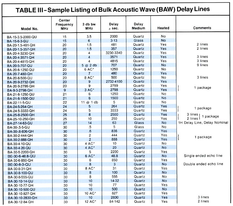
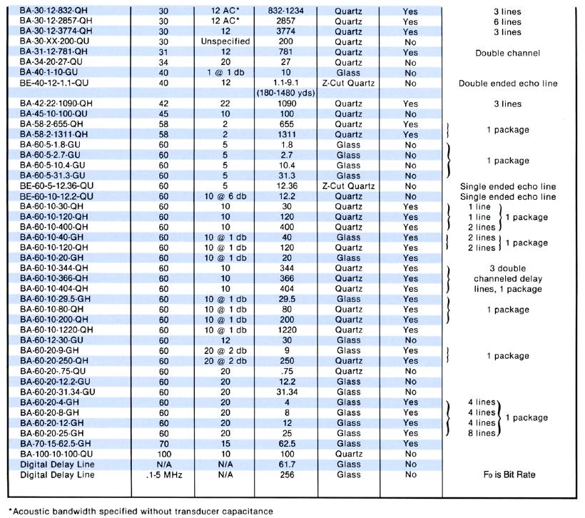
3 certain asymmetric crystals or polycrystalline materials are subjected to an electric field, mechanical stress or strain is produced in the material; conversely, when subjected to mechanical stress or strain, electrical charges will collect on specific surfaces of the piezoelectric material. Piezoelectric materials are therefore used to both produce and detect mechanical, or acoustic, vibration in a given medium. A basic BAW delay line is comprised of two piezoelectric transducers bonded to a low velocity medium such as quartz or glass. The time delay is determined by both the acoustic velocity and the length of the path to be traversed by the acoustic wave. The medium, therefore, can have any number of geometrical configurations employing internal reflections from surface interfaces to increase the path length and minimize the volume. The simplest geometry is that of a rectangular bar (Figure 1A) with piezoelectric transducers bonded to each end. An electrical signal is applied to the input transducer and converted to an acoustic signal. This acoustic signal is then transmitted through the solid medium to the output transducer where it is detected and converted back to an electrical signal. Figure 1B depicts a typical double bounce beam pat- tern and placement of acoustic damping material to attenuate unwanted spurious signals. In general, delays over 50 microseconds are accomplished through means of multiple internal reflections as shown in Figure 1C. Types of BAW Delay Lines As shown in Figure 2, three types of Andersen BAW delay lines are available: Standard Delay Lines -This configuration is used for applications requiring a specific signal delay with broadband frequency characteristics and good suppression of unwanted time responses. Typical applications include TV broadcast and receiving equipment, airborne transponders, image processing, radar MTI and video integrator circuits. Echo Delay Lines -These devices yield multiple, precisely delayed outputs from a single input pulse. Typical applications include radar range calibration and amplifier linearity calibration. Digital Delay Lines -This configuration is used in digital circuits to store and delay bits of unmodulated video signals.
4 Typical Performance Range The practical "standard-device" performance range for each key parameter is shown in Table I. These performance ranges are presented here only as general selection guidelines and do not necessarily constitute design limitations. The type, configuration and performance of a BAW device are affected by many interrelated factors. For performance requirements beyond those shown in Table I, consult Andersen Laboratories. Delay Delay can be measured at fₒ or across the entire band. While the delay will vary across the band, these variations (otherwise known as Group Delay) can be kept to within a few nanoseconds of the average value across a wide band as shown in Fig. 3. Delay Media The propagation velocities of the delay media primarily used in Andersen designs -fused quartz, crystalline quartz and zero-temperature coefficient glass - are shown in Table II. The velocity at which an acoustic wave travels through a medium depends on the manner in which the wave is generated by the transducer (shear mode or compressional mode). A shear mode wave travels at a slower velocity than a compressional mode wave and therefore requires a shorter beam path for a given delay. In addition, compressional mode waves cannot always be reflected satisfactorily within the medium. Therefore, shear mode transducers are generally used for most SAW delay lines. Fused quartz is the delay medium most frequently used for standard BAW delay lines. Its acoustic loss constant is low, enabling large storages to be obtained with good insertion loss performance (see Fig. 5). By using multiple internal reflections, delays of up to 5,000 microseconds can be achieved with a single device. This is a practical upper limit for individual devices since it is difficult and costly to obtain satisfactory fused quartz large enough to accommodate internally reflected signal paths longer than 745 inches. For delays in excess of 5,000 microseconds, individual devices can be cascaded. Zero-temperature coefficient glass is another widely used delay medium. A shear mode wave travels at a slower velocity in glass than in fused quartz, which
5 allows for shorter beam paths in glass. The other advantages of this medium are better bandwidth characteristics at low frequencies and extreme temperature stability (see Fig. 4). Glass. however. has a higher insertion loss than fused quartz (see Fig. 5) and is therefore used primarily for delays up to 200 µs. Z-A xis crystalline quartz is used primarily for Echo Delay Lines. Its neutral polarization and temperature coefficient of +80ppm/ C make it an optimum medium for delayed multiple echo applications. A pulse train is achieved by launching a compressional mode wave from one end of a crystalline quartz bar to the other end. The highly reflective end facets initiate internal reflections which support numerous back-and-forth cycles of the beam, creating the output echos. The low acoustic loss constant of crystalline quartz (see Fig. 5) supports minimum echo-to-echo attenuation while maintaining a linear amplitude degradation. Fused Quartz Crystalline Quartz Zero Temperature Coefficient Glass TABLE II Propagation Velocities of Various Delay Media (at +25 C) Shear Mode Wave Approx. 6.7 µ.sec/in. Not Applicable Approx. 9.8 µ.sec/in. shear mode waves cannot be propagated satisfactorily in crystalllne quartz. Compressional Mode Wave Approx. 4.3 µ.sec/in. Approx. 4.3 µ.sec/in. Approx. 5.8 µ.sec/in.
6 Temperature and Delay Stability Figure 4 shows how delay time changes in glass with changes in ambient temperature. Glass has a TCDT (Temperature Coefficient of Delay Time) of ppm/ C 2. This equates to a parabolic function with the zero temperature coefficient intersect at approximately +55 C. Fused quartz has a TCDT of approximately -75 ppm/ C. This means that for a delay of 1000 µs there is a variance of.075 µs per C. When extreme loss and delay stability is required, the temperature of the fused quartz delay medium is controlled by incorporating the medium in a single or double oven. This packaging technique can maintain the internal temperature to within ± 0.01 C over an ambient range of greater than 100 c. Center Frequency The fundamental center frequency of a BAW delay line is governed by the thickness of the transducers as follows: A center frequency of 150 MHz represents a practical upper limit for most devices because of the difficulty in fabricating transducers of sufficient thinness for higher frequency operation. However, devices can be tuned and optimized for a third harmonic output with the same bandwidth as the fundamentaloutput.
7 Bandwidth A common generalization is that the overall bandwidth referenced to 3dB points will approximate 50% of the center frequency. In certain cases, 90% bandwidths have been achieved. Bandwidth is affected by transducer performance and the effects of the delay medium on the ultrasonic wave. For short delays, the medium effects are negligible due to the short beam path. While it is possible to achieve long delays with wide bandwidths, loss can become an issue because of "beam spreading" (diffraction) for long beam paths. Insertion Loss Figure 5 shows the medium loss for fused quartz, glass and crystalline quartz as a function of db/µs as related to frequency. The graphed results represent the friction loss of the medium only and are independent of all other effects. It should be noted that the loss constant significantly decreases with heat. Medium loss is a major component of total insertion loss. Losses due to beam spreading (diffraction losses) are only a concern in lines that combine long delays and low frequencies. Transducer loss is generally not a factor either, since transducer systems with essentially zero loss can be provided using computer-aided design techniques. While there is no concise formula that fully defines the relationship between medium loss, center frequency and delay, the following empirical formulas closely approximate this relationship. Hence, a fused quartz 300 µs delay line with a center frequency of 30 MHz would have a medium loss of 3.4 db (excluding any diffraction or transducer loss). The same 300 µs delay line at 150 MHz would have a medium loss of db. Generally speaking, increases in loss occur with increases in delay time and/or frequency.
8 Transducer Match A critical factor in the performance of a BAW device is the design of the transducer assembly. The better the match between transducers, medium, and external electrical circuitry, the better the performance characteristics of the delay line, particularly for insertion loss and triple travel. Transducer materials used include crystalline quartz, titanates and niobates. Andersen has developed proprietary methods to insure good impedance match between the transducer, delay medium and external electrical circuitry to achieve maximum signal transfer with minimum distortion and unwanted time responses. Unwanted Time Responses Unwanted time responses which appear at the delay line output may originate from any of a variety of causes. Maximum permissible levels for each type of response are referenced to the output signal and generally specified by the customer. The four most common types of unwanted responses are discussed below. Feedthrough (FT)...FT occurs when the input electrical signal is capacitively transferred from the input transducer directly to the output transducer. FT is minimized by shielding and grounding techniques and is readily suppressed to greater than 50 db. Triple Travel (TT)..TI is caused by a slight impedance mismatch between the transducer, delay medium and external electrical circuitry. A small portion of the ultrasonic wave striking the output transducer is reflected. This reflection reverses its path, strikes the input transducer, and is reflected back to the output transducer once more. The result is a signal at three times the delay. Andersen has developed improved impedance matching techniques and acoustic damping methods to reduce TI. For short delay lines, TI is suppressed to greater than 40 db, and greater than 50 db for longer lines. Figure 6 shows the effect of TI on amplitude, phase and delay ripple.
9 Random Signals (RS) When a transducer launches an ultrasonic wave, side lobes are generated which may follow different reflection paths through the delay medium. These "random" signals will arrive at the output transducer at delays substantially different from the specified delay. Through acoustic damping methods, RS is suppressed to greater than 50 db. Cross-talk (CT) CT is electromagnetic in nature and occurs in multi-line packages where an unwanted signal from one line is displayed at the output of another line. Through careful shielding, CT is suppressed to greater than 60 db in standard devices. Power Handling Power handling is limited by the amount of heat the transducer is able to dissipate. A typical value is + 21 dbm, but depending upon design, this may be increased to over + 30 dbm. Phase Linearity Utilizing computerized test equipment, the phase response of a given delay line is referenced to zero and displayed linearly across the frequency band of interest. Any unwanted time responses will create slight variations in the phase shape. Phase linearities of 3 peak-to-peak are typical and phase linearities of 0.75 peak-to-peak have been achieved.
10
11
12 Representative Applications for BAW Delay Lines Illustrated on the following pages are just a few of the typical applications for which Andersen has provided SAW delay lines. While some lines are high volume catalog-type products, most were designed and built to optimize a specific systems' performance.
13
14
15 Design Flexibility Andersen Laboratories has the design and production capabilities to provide not only individual SAW delay lines but complete IF signal processing subsystems as well (e.g. pulse stretchers, moving target indicators, unity gain modules, etc.). Incorporating Bulk Acoustic Wave delay lines with other electronic functions, these subsystems optimize the performance potential of this technology for specific system requirements. Whether you require components or subsystems, Andersen SAW technology lends itself to a wide range of packaging techniques to meet special physical or electrical system constraints. Packaging for individual delay lines ranges from PCboard pin modules to units with RF connectors (and DC power connectors where ovens are involved). Subsystem packaging can range from simple boxes with RF and DC connectors to rack mounted drawers. Hopefully, this volume has given you a fundamental overview of BAW delay lines, but in no way does it reflect the full potential of this technology, a technology uniquely capable of fulfilling many of today s and tomorrow s requirements with a simplicity unmatched by other signal processing methods.
Piezo-Ceramic Glossary
 Version: March 1, 2017 Electronics Tech. Piezo-Ceramic Glossary Web: www.direct-token.com Email: rfq@direct-token.com Direct Electronics Industry Co., Ltd. China: 12F, Zhong Xing Industry Bld., Chuang
DESIGN OF GLOBAL SAW RFID TAG DEVICES C. S. Hartmann, P. Brown, and J. Bellamy RF SAW, Inc., 900 Alpha Drive Ste 400, Richardson, TX, U.S.A.
 DESIGN OF GLOBAL SAW RFID TAG DEVICES C. S. Hartmann, P. Brown, and J. Bellamy RF SAW, Inc., 900 Alpha Drive Ste 400, Richardson, TX, U.S.A., 75081 Abstract - The Global SAW Tag [1] is projected to be
FS5000 COMSTRON. The Leader In High Speed Frequency Synthesizers. An Ideal Source for: Agile Radar and Radar Simulators.
 FS5000 F R E Q U E N C Y S Y N T H E S I Z E R S Ultra-fast Switching < 200 nsec Wide & Narrow Band Exceptionally Clean An Ideal Source for: Agile Radar and Radar Simulators Radar Upgrades Fast Antenna
1, Bandwidth (Hz) ,
 ,") A Crystal Filter Tutorial Abstract: The general topic of crystal filters will be discussed in a manner that is intended to help the user to better understand, specify, test, and use them. The center frequency
A Crystal Filter Tutorial Abstract: The general topic of crystal filters will be discussed in a manner that is intended to help the user to better understand, specify, test, and use them. The center frequency
Optical Delay Line Application Note
 1 Optical Delay Line Application Note 1.1 General Optical delay lines system (ODL), incorporates a high performance lasers such as DFBs, optical modulators for high operation frequencies, photodiodes,
A 1-W GaAs Class-E Power Amplifier with an FBAR Filter Embedded in the Output Network
 A 1-W GaAs Class-E Power Amplifier with an FBAR Filter Embedded in the Output Network Kyle Holzer and Jeffrey S. Walling University of Utah PERFIC Lab, Salt Lake City, UT 84112, USA Abstract Integration
High Dynamic Range Receiver Parameters
 High Dynamic Range Receiver Parameters The concept of a high-dynamic-range receiver implies more than an ability to detect, with low distortion, desired signals differing, in amplitude by as much as 90
GHz-band, high-accuracy SAW resonators and SAW oscillators
 The evolution of wireless communications and semiconductor technologies is spurring the development and commercialization of a variety of applications that use gigahertz-range frequencies. These new applications
RADIO RECEIVERS ECE 3103 WIRELESS COMMUNICATION SYSTEMS
 RADIO RECEIVERS ECE 3103 WIRELESS COMMUNICATION SYSTEMS FUNCTIONS OF A RADIO RECEIVER The main functions of a radio receiver are: 1. To intercept the RF signal by using the receiver antenna 2. Select the
Voltage Controlled SAW Oscillator Mechanical Shock Compensator
 Voltage Controlled SAW Oscillator Mechanical Shock Compensator ECE 4901 - Senior Design I Fall 2012 Project Proposal ECE Project Members: Joseph Hiltz-Maher Max Madore Shalin Shah Shaun Hew Faculty Advisor:
ANTENNA INTRODUCTION / BASICS
 ANTENNA INTRODUCTION / BASICS RULES OF THUMB: 1. The Gain of an antenna with losses is given by: 2. Gain of rectangular X-Band Aperture G = 1.4 LW L = length of aperture in cm Where: W = width of aperture
Integrated Microwave Assemblies
 Integrated Microwave Assemblies Integrated Microwave Assembly (IMA) Custom Solutions For more information please call us at 888.553.7531 API Technologies, a world class leader in component design and system
CHAPTER 6 EMI EMC MEASUREMENTS AND STANDARDS FOR TRACKED VEHICLES (MIL APPLICATION)
") 147 CHAPTER 6 EMI EMC MEASUREMENTS AND STANDARDS FOR TRACKED VEHICLES (MIL APPLICATION) 6.1 INTRODUCTION The electrical and electronic devices, circuits and systems are capable of emitting the electromagnetic
147 CHAPTER 6 EMI EMC MEASUREMENTS AND STANDARDS FOR TRACKED VEHICLES (MIL APPLICATION) 6.1 INTRODUCTION The electrical and electronic devices, circuits and systems are capable of emitting the electromagnetic
Application Instruction 002. Superluminescent Light Emitting Diodes: Device Fundamentals and Reliability
 I. Introduction II. III. IV. SLED Fundamentals SLED Temperature Performance SLED and Optical Feedback V. Operation Stability, Reliability and Life VI. Summary InPhenix, Inc., 25 N. Mines Road, Livermore,
HF Receivers, Part 2
 HF Receivers, Part 2 Superhet building blocks: AM, SSB/CW, FM receivers Adam Farson VA7OJ View an excellent tutorial on receivers NSARC HF Operators HF Receivers 2 1 The RF Amplifier (Preamp)! Typical
Designing Next-Generation AESA Radar Part 2: Individual Antenna Design
 Design Designing Next-Generation AESA Radar Part 2: Individual Antenna Design Figure 8: Antenna design Specsheet user interface showing the electrical requirements input (a), physical constraints input
Introduction to SAW Filter Theory & Design Techniques
 Introduction to SAW Filter Theory & Design Techniques Introduction API Technologies offers a wide range of high quality standard and custom Surface Acoustic Wave (SAW) product solutions. API believes in
Keysight Technologies Making Accurate Intermodulation Distortion Measurements with the PNA-X Network Analyzer, 10 MHz to 26.5 GHz
 Keysight Technologies Making Accurate Intermodulation Distortion Measurements with the PNA-X Network Analyzer, 10 MHz to 26.5 GHz Application Note Overview This application note describes accuracy considerations
Attenuation and velocity of ultrasound in solid state materials (transmission)
") Attenuation and velocity of ultrasound in solid 5.1.6.08 Related Topics Propagation of ultrasonic waves, time of flight, sound velocity, damping of ultrasonic waves (scattering, reflection, absorption),
Attenuation and velocity of ultrasound in solid 5.1.6.08 Related Topics Propagation of ultrasonic waves, time of flight, sound velocity, damping of ultrasonic waves (scattering, reflection, absorption),
RECENT ADVANCEMENTS IN THE APPLICATION OF EMATS TO NDE
 RECENT ADVANCEMENTS IN THE APPLICATION OF EMATS TO NDE D. MacLauchlan, S. Clark, B. Cox, T. Doyle, B. Grimmett, J. Hancock, K. Hour, C. Rutherford BWXT Services, Non Destructive Evaluation and Inspection
Model Series 400X User s Manual. DC-100 MHz Electro-Optic Phase Modulators
 Model Series 400X User s Manual DC-100 MHz Electro-Optic Phase Modulators 400412 Rev. D 2 Is a registered trademark of New Focus, Inc. Warranty New Focus, Inc. guarantees its products to be free of defects
Low Cost Mixer for the 10.7 to 12.8 GHz Direct Broadcast Satellite Market
 Low Cost Mixer for the.7 to 12.8 GHz Direct Broadcast Satellite Market Application Note 1136 Introduction The wide bandwidth requirement in DBS satellite applications places a big performance demand on
Lesson 02: Sound Wave Production. This lesson contains 24 slides plus 11 multiple-choice questions.
 Lesson 02: Sound Wave Production This lesson contains 24 slides plus 11 multiple-choice questions. Accompanying text for the slides in this lesson can be found on pages 2 through 7 in the textbook: ULTRASOUND
Television and video engineering
 Television and video engineering Unit-4 Television Receiver systems Objectives: To learn the requirements of TV receiver Study of monochrome and Colour TV receivers. To learn functions of Tuning circuits
Transducer product selector
 Transducer product selector Precision Acoustics Ltd (PA) is pleased to offer a wide range of transducers. PA does not have a catalogue of standard transducers; instead each transducer we supply is custom
ANTENNA INTRODUCTION / BASICS
 Rules of Thumb: 1. The Gain of an antenna with losses is given by: G 0A 8 Where 0 ' Efficiency A ' Physical aperture area 8 ' wavelength ANTENNA INTRODUCTION / BASICS another is:. Gain of rectangular X-Band
Bill Ham Martin Ogbuokiri. This clause specifies the electrical performance requirements for shielded and unshielded cables.
 098-219r2 Prepared by: Ed Armstrong Zane Daggett Bill Ham Martin Ogbuokiri Date: 07-24-98 Revised: 09-29-98 Revised again: 10-14-98 Revised again: 12-2-98 Revised again: 01-18-99 1. REQUIREMENTS FOR SPI-3
8791 Power Tube. Linear Beam Power Amplifier Tube
 8791 Power Tube Linear Beam Power Amplifier Tube Ruggedized, Reliable 80 Watt Average-Noise-Power Output with White Noise Loading 250 Watt Power Output in VHF-Linear Translator Service 500 Watt PEP Output
Rec. ITU-R F RECOMMENDATION ITU-R F *
 Rec. ITU-R F.162-3 1 RECOMMENDATION ITU-R F.162-3 * Rec. ITU-R F.162-3 USE OF DIRECTIONAL TRANSMITTING ANTENNAS IN THE FIXED SERVICE OPERATING IN BANDS BELOW ABOUT 30 MHz (Question 150/9) (1953-1956-1966-1970-1992)
Equipment for Attenuation and velocity of ultrasound in solid state materials (transmission), experimental set-up
, experimental set-up") Attenuation and velocity of ultrasound in solid TEAS Related Topics Propagation of ultrasonic waves, time of flight, sound velocity, damping of ultrasonic waves (scattering, reflection, absorption), transmission
Attenuation and velocity of ultrasound in solid TEAS Related Topics Propagation of ultrasonic waves, time of flight, sound velocity, damping of ultrasonic waves (scattering, reflection, absorption), transmission
Linearity Improvement Techniques for Wireless Transmitters: Part 1
 From May 009 High Frequency Electronics Copyright 009 Summit Technical Media, LLC Linearity Improvement Techniques for Wireless Transmitters: art 1 By Andrei Grebennikov Bell Labs Ireland In modern telecommunication
Microwave Fundamentals A Survey of Microwave Systems and Devices p. 3 The Relationship of Microwaves to Other Electronic Equipment p.
 Microwave Fundamentals A Survey of Microwave Systems and Devices p. 3 The Relationship of Microwaves to Other Electronic Equipment p. 3 Microwave Systems p. 5 The Microwave Spectrum p. 6 Why Microwave
ACOUSTIC MICRO IMAGING ANALYSIS METHODS FOR 3D PACKAGES
 ACOUSTIC MICRO IMAGING ANALYSIS METHODS FOR 3D PACKAGES Janet E. Semmens Sonoscan, Inc. Elk Grove Village, IL, USA Jsemmens@sonoscan.com ABSTRACT Earlier studies concerning evaluation of stacked die packages
"Natural" Antennas. Mr. Robert Marcus, PE, NCE Dr. Bruce C. Gabrielson, NCE. Security Engineering Services, Inc. PO Box 550 Chesapeake Beach, MD 20732
 Published and presented: AFCEA TEMPEST Training Course, Burke, VA, 1992 Introduction "Natural" Antennas Mr. Robert Marcus, PE, NCE Dr. Bruce C. Gabrielson, NCE Security Engineering Services, Inc. PO Box
Receiver Design. Prof. Tzong-Lin Wu EMC Laboratory Department of Electrical Engineering National Taiwan University 2011/2/21
 Receiver Design Prof. Tzong-Lin Wu EMC Laboratory Department of Electrical Engineering National Taiwan University 2011/2/21 MW & RF Design / Prof. T. -L. Wu 1 The receiver mush be very sensitive to -110dBm
IPC TECHNICAL PAPER SERIES NUMBER 310
 THE INSTITUTE OF PAPER CHEMISTRY, APPLETON, WISCONSIN IPC TECHNICAL PAPER SERIES NUMBER 310 THE DEVELOPMENT OF A DOUBLE ELEMENT, PULSE ECHO, PVDF TRANSDUCER C. C. HABEGER AND W. A. WINK DECEMBER, 1988
UNIVERSITI MALAYSIA PERLIS
 UNIVERSITI MALAYSIA PERLIS SCHOOL OF COMPUTER & COMMUNICATIONS ENGINEERING EKT 341 LABORATORY MODULE LAB 2 Antenna Characteristic 1 Measurement of Radiation Pattern, Gain, VSWR, input impedance and reflection
Measurement of conducted EMI when using a switching power supply
 EMC/FIELD STRENGTH A new firmware module has been developed for the R&S ESPI (FIG 1) that further facilitates EMI emission Precompliance Test Receiver R&S ESPI Measurement of conducted EMI when using a
Characteristics of Crystal. Piezoelectric effect of Quartz Crystal
 Characteristics of Crystal Piezoelectric effect of Quartz Crystal The quartz crystal has a character when the pressure is applied to the direction of the crystal axis, the electric change generates on
Measurements with Scattering Parameter By Joseph L. Cahak Copyright 2013 Sunshine Design Engineering Services
 Measurements with Scattering Parameter By Joseph L. Cahak Copyright 2013 Sunshine Design Engineering Services Network Analyzer Measurements In many RF and Microwave measurements the S-Parameters are typically
Standard Guide for Evaluating Characteristics of Ultrasonic Search Units 1
 Designation: E 1065 99 An American National Standard Standard Guide for Evaluating Characteristics of Ultrasonic Search Units 1 This standard is issued under the fixed designation E 1065; the number immediately
the pilot valve effect of
 Actiive Feedback Control and Shunt Damping Example 3.2: A servomechanism incorporating a hydraulic relay with displacement feedback throughh a dashpot and spring assembly is shown below. [Control System
Limiter Diodes Features Description Chip Dimensions Model DOT Diameter (Typ.) Chip Number St l Style Inches 4 11
 Chip Number St l Style Inches 4 11") Features Low Loss kw Coarse Limiters 200 Watt Midrange Limiters 10 mw Clean Up Limiters 210 20 Description Alpha has pioneered the microwave limiter diode. Because all phases of manufacturing, from design
Features Low Loss kw Coarse Limiters 200 Watt Midrange Limiters 10 mw Clean Up Limiters 210 20 Description Alpha has pioneered the microwave limiter diode. Because all phases of manufacturing, from design
Improving Amplitude Accuracy with Next-Generation Signal Generators
 Improving Amplitude Accuracy with Next-Generation Signal Generators Generate True Performance Signal generators offer precise and highly stable test signals for a variety of components and systems test
VHF LAND MOBILE SERVICE
 RFS21 December 1991 (Issue 1) SPECIFICATION FOR RADIO APPARATUS: VHF LAND MOBILE SERVICE USING AMPLITUDE MODULATION WITH 12.5 khz CARRIER FREQUENCY SEPARATION Communications Division Ministry of Commerce
1. Explain how Doppler direction is identified with FMCW radar. Fig Block diagram of FM-CW radar. f b (up) = f r - f d. f b (down) = f r + f d
 = f r - f d. f b (down) = f r + f d") 1. Explain how Doppler direction is identified with FMCW radar. A block diagram illustrating the principle of the FM-CW radar is shown in Fig. 4.1.1 A portion of the transmitter signal acts as the reference
1. Explain how Doppler direction is identified with FMCW radar. A block diagram illustrating the principle of the FM-CW radar is shown in Fig. 4.1.1 A portion of the transmitter signal acts as the reference
Spectrum Analyzer R&S FS300
 Spectrum Analyzer R&S FS300 9 khz to 3 GHz The new product family from Rohde & Schwarz Professional test equipment for laboratory, service and production The R&S FS300 is a highly accurate spectrum analyzer
Application Note SAW-Components
 RF360 Europe GmbH A Qualcomm TDK Joint Venture Application Note SAW-Components App. Note 19 Abstract: The characteristics of surface acoustic wave (SAW) filters are presented in order to find a suitable
Pulse Compression. Since each part of the pulse has unique frequency, the returns can be completely separated.
 Pulse Compression Pulse compression is a generic term that is used to describe a waveshaping process that is produced as a propagating waveform is modified by the electrical network properties of the transmission
Recirculating Loop System (No Frequency Shift) AMM C-RLS(nfs)-RM
 AMM C-RLS(nfs)-RM") Recirculating Loop System (No Frequency Shift) AMM-100-8-70-C-RLS(nfs)-RM KEY FEATURES R F D R I V E R R E C I R C U L A T I N G L O O P S Y S T E M D I A G R A M Low Insertion Loss No O-rings Rack-mount
Recirculating Loop System (No Frequency Shift) AMM-100-8-70-C-RLS(nfs)-RM KEY FEATURES R F D R I V E R R E C I R C U L A T I N G L O O P S Y S T E M D I A G R A M Low Insertion Loss No O-rings Rack-mount
KULLIYYAH OF ENGINEERING
 KULLIYYAH OF ENGINEERING DEPARTMENT OF ELECTRICAL & COMPUTER ENGINEERING ANTENNA AND WAVE PROPAGATION LABORATORY (ECE 4103) EXPERIMENT NO 3 RADIATION PATTERN AND GAIN CHARACTERISTICS OF THE DISH (PARABOLIC)
Low Distortion Mixer AD831
 a FEATURES Doubly-Balanced Mixer Low Distortion +2 dbm Third Order Intercept (IP3) + dbm 1 db Compression Point Low LO Drive Required: dbm Bandwidth MHz RF and LO Input Bandwidths 2 MHz Differential Current
CIRCULATOR APPLICATION NOTE ANV001.
 APPLICATION NOTE ANV001 Bötelkamp 31, D-22529 Hamburg, GERMANY Phone: +49-40 547 544 60 Fax: +49-40 547 544 666 Email: info@valvo.com A Circulator is defined as a non-reciprocal, passive three ports, ferromagnetic
10 GHz LNA for Amateur Radio by K5TRA
 Introduction Ham radio operation on 10 GHz is somewhat exotic. This is far removed from global short-wave communication below 30 MHz, or regional VHF and UHF communication. Despite the arcane nature of
Termination Insensitive Mixers By Howard Hausman President/CEO, MITEQ, Inc. 100 Davids Drive Hauppauge, NY
 Termination Insensitive Mixers By Howard Hausman President/CEO, MITEQ, Inc. 100 Davids Drive Hauppauge, NY 11788 hhausman@miteq.com Abstract Microwave mixers are non-linear devices that are used to translate
Welcome to the Epson SAW oscillator product training module. Epson has been providing their unique SAW oscillators that exhibit outstanding
 Welcome to the Epson SAW oscillator product training module. Epson has been providing their unique SAW oscillators that exhibit outstanding stability, ultra low jitter and the ability to oscillate at a
FISCHER CUSTOM COMMUNICATIONS, INC.
 FISCHER CUSTOM COMMUNICATIONS, INC. Current Probe Catalog FISCHER CUSTOM COMMUNICATIONS, INC. Fischer Custom Communications, Inc., is a manufacturer of custom electric and magnetic field sensors for military
ENGINEERING COMMITTEE Interface Practices Subcommittee AMERICAN NATIONAL STANDARD ANSI/SCTE
 ENGINEERING COMMITTEE Interface Practices Subcommittee AMERICAN NATIONAL STANDARD ANSI/SCTE 82 2012 Test Method for Low Frequency and Spurious Disturbances NOTICE The Society of Cable Telecommunications
There is a twenty db improvement in the reflection measurements when the port match errors are removed.
 ABSTRACT Many improvements have occurred in microwave error correction techniques the past few years. The various error sources which degrade calibration accuracy is better understood. Standards have been
BASICS OF ANTENNAS Lecture Note 1
 BASICS OF ANTENNAS Lecture Note 1 INTRODUCTION Antennas are devices that are capable of launching RF (radio frequency) energy into space and detect it as well. How well an antenna is able to launch RF
International Distinguished Lecturer Program
 U 2005-2006 International Distinguished Lecturer Program Ken-ya Hashimoto Chiba University Sponsored by The Institute of Electrical and Electronics Engineers (IEEE) Ultrasonics, Ferroelectrics and Frequency
3-2 Measurement of Unwanted Emissions of Marine Radar System
 3 Research and Development of Testing Technologies for Radio Equipment 3-2 Measurement of Unwanted Emissions of Marine Radar System Hironori KITAZAWA and Sadaaki SHIOTA To consider the effective use of
Technician License Course Chapter 4. Lesson Plan Module 9 Antenna Fundamentals, Feed Lines & SWR
 Technician License Course Chapter 4 Lesson Plan Module 9 Antenna Fundamentals, Feed Lines & SWR The Antenna System Antenna: Transforms current into radio waves (transmit) and vice versa (receive). Feed
2. Pulsed Acoustic Microscopy and Picosecond Ultrasonics
 1st International Symposium on Laser Ultrasonics: Science, Technology and Applications July 16-18 2008, Montreal, Canada Picosecond Ultrasonic Microscopy of Semiconductor Nanostructures Thomas J GRIMSLEY
Chapter-2 LOW PASS FILTER DESIGN 2.1 INTRODUCTION
 Chapter-2 LOW PASS FILTER DESIGN 2.1 INTRODUCTION Low pass filters (LPF) are indispensable components in modern wireless communication systems especially in the microwave and satellite communication systems.
EDCRO-200 is a stable ceramic based, sampling phase locked oscillator.
 EDCRO-200 is a stable ceramic based, sampling phase locked oscillator. Commercial Military Airborne Space Missile Guidance Cable TV Links (CATV) Satellite Communications Low Cost External Reference Military/Commercial
Design of Crossbar Mixer at 94 GHz
 Wireless Sensor Network, 2015, 7, 21-26 Published Online March 2015 in SciRes. http://www.scirp.org/journal/wsn http://dx.doi.org/10.4236/wsn.2015.73003 Design of Crossbar Mixer at 94 GHz Sanjeev Kumar
IPC-TM-650 TEST METHODS MANUAL
 SSOCITION CONNECTING ELECTRONICS INDUSTRIES 2215 Sanders Road Northbrook, IL 60062-6135 TEST METHODS MNUL Originating Task Group N/ 1.0 Scope 3.3 Fixturing 1.1 To determine the effect on the connector
The Simulation for Ultrasonic Testing Based on Frequency-Phase Coded Excitation
 1 8 nd International Conference on Physical and Numerical Simulation of Materials Processing, ICPNS 16 Seattle Marriott Waterfront, Seattle, Washington, USA, October 14-17, 2016 The Simulation for Ultrasonic
General Application Notes Remote Sense Remote On / Off Output Trim Series Operation Parallel Operation...
 General... 28 Remote Sense... 29 Remote On / Off... 30 Output Trim... 30 Series Operation... 32 Parallel Operation... 33 Synchronization... 33 Power Good Signal... 34 Electro Magnetic Filter (EMI)... 34
MAHALAKSHMI ENGINEERING COLLEGE TIRUCHIRAPALLI UNIT III TUNED AMPLIFIERS PART A (2 Marks)
") MAHALAKSHMI ENGINEERING COLLEGE TIRUCHIRAPALLI-621213. UNIT III TUNED AMPLIFIERS PART A (2 Marks) 1. What is meant by tuned amplifiers? Tuned amplifiers are amplifiers that are designed to reject a certain
MAHALAKSHMI ENGINEERING COLLEGE TIRUCHIRAPALLI-621213. UNIT III TUNED AMPLIFIERS PART A (2 Marks) 1. What is meant by tuned amplifiers? Tuned amplifiers are amplifiers that are designed to reject a certain
SAW Filter PCB Layout
 SAW Filter PCB Layout by Allan Coon Director, Filter Product Marketing Murata Electronics North America, c. 1999 troduction The performance of surface acoustic wave (SAW) filters depends on a number of
Recon UWB Antenna for Cognitive Radio
 Progress In Electromagnetics Research C, Vol. 79, 79 88, 2017 Recon UWB Antenna for Cognitive Radio DeeplaxmiV.Niture *, Santosh S. Jadhav, and S. P. Mahajan Abstract This paper talks about a simple printed
A NEW APPROACH FOR THE ANALYSIS OF IMPACT-ECHO DATA
 A NEW APPROACH FOR THE ANALYSIS OF IMPACT-ECHO DATA John S. Popovics and Joseph L. Rose Department of Engineering Science and Mechanics The Pennsylvania State University University Park, PA 16802 INTRODUCTION
Waveguides. Metal Waveguides. Dielectric Waveguides
 Waveguides Waveguides, like transmission lines, are structures used to guide electromagnetic waves from point to point. However, the fundamental characteristics of waveguide and transmission line waves
Keywords: Ultrasonic Testing (UT), Air-coupled, Contact-free, Bond, Weld, Composites
, Air-coupled, Contact-free, Bond, Weld, Composites") Single-Sided Contact-Free Ultrasonic Testing A New Air-Coupled Inspection Technology for Weld and Bond Testing M. Kiel, R. Steinhausen, A. Bodi 1, and M. Lucas 1 Research Center for Ultrasonics - Forschungszentrum
Single-Sided Contact-Free Ultrasonic Testing A New Air-Coupled Inspection Technology for Weld and Bond Testing M. Kiel, R. Steinhausen, A. Bodi 1, and M. Lucas 1 Research Center for Ultrasonics - Forschungszentrum
Effect of coupling conditions on ultrasonic echo parameters
 J. Pure Appl. Ultrason. 27 (2005) pp. 70-79 Effect of coupling conditions on ultrasonic echo parameters ASHOK KUMAR, NIDHI GUPTA, REETA GUPTA and YUDHISTHER KUMAR Ultrasonic Standards, National Physical
Output Filtering & Electromagnetic Noise Reduction
 Output Filtering & Electromagnetic Noise Reduction Application Note Assignment 14 November 2014 Stanley Karas Abstract The motivation of this application note is to both review what is meant by electromagnetic
Mathematical Modeling of Ultrasonic Phased Array for Obstacle Location for Visually Impaired
 IOSR Journal of VLSI and Signal Processing (IOSR-JVSP) Volume 2, Issue 6 (Jul. Aug. 2013), PP 52-56 e-issn: 2319 4200, p-issn No. : 2319 4197 Mathematical Modeling of Ultrasonic Phased Array for Obstacle
RECEIVER SENSITIVITY / NOISE
 RECEIVER SENSITIVITY / NOISE RECEIVER SENSITIVITY Sensitivity in a receiver is normally taken as the imum input signal (S ) required to produce a specified output signal having a specified signal-to-noise
Module 8 Theory. dbs AM Detector Ring Modulator Receiver Chain. Functional Blocks Parameters. IRTS Region 4
 Module 8 Theory dbs AM Detector Ring Modulator Receiver Chain Functional Blocks Parameters Decibel (db) The term db or decibel is a relative unit of measurement used frequently in electronic communications
A SHEAR WAVE TRANSDUCER ARRAY FOR REAL-TIME IMAGING. R.L. Baer and G.S. Kino. Edward L. Ginzton Laboratory Stanford University Stanford, CA 94305
 A SHEAR WAVE TRANSDUCER ARRAY FOR REAL-TIME IMAGING R.L. Baer and G.S. Kino Edward L. Ginzton Laboratory Stanford University Stanford, CA 94305 INTRODUCTION In this paper we describe a contacting shear
SHIELDING EFFECTIVENESS
 SHIELDING Electronic devices are commonly packaged in a conducting enclosure (shield) in order to (1) prevent the electronic devices inside the shield from radiating emissions efficiently and/or (2) prevent
Miniature, High Efficiency Transducers For Use IN Ultrasonic Flow Meters
 Marquette University e-publications@marquette Master's Theses (2009 -) Dissertations, Theses, and Professional Projects Miniature, High Efficiency Transducers For Use IN Ultrasonic Flow Meters Meghna Saikia
Four-Channel Sample-and-Hold Amplifier AD684
 a FEATURES Four Matched Sample-and-Hold Amplifiers Independent Inputs, Outputs and Control Pins 500 ns Hold Mode Settling 1 s Maximum Acquisition Time to 0.01% Low Droop Rate: 0.01 V/ s Internal Hold Capacitors
APPLICATION NOTE LZY-1 ULTRA-LINEAR RF AMPLIFIER. 20 MHz MHz 25 WATTS MIN., 1 db COMPRESSION (50 WATTS TYP., MAX. OUTPUT)
") AN-60-004 APPLICATION NOTE LZY-1 ULTRA-LINEAR RF AMPLIFIER 20 MHz - 512 MHz 25 WATTS MIN., 1 db COMPRESSION (50 WATTS TYP., MAX. OUTPUT) Reviewed by: Jack Semizian Radha Setty INTERNET http://www.minicircuits.com
AN-60-004 APPLICATION NOTE LZY-1 ULTRA-LINEAR RF AMPLIFIER 20 MHz - 512 MHz 25 WATTS MIN., 1 db COMPRESSION (50 WATTS TYP., MAX. OUTPUT) Reviewed by: Jack Semizian Radha Setty INTERNET http://www.minicircuits.com
Data Sheet SC5317 & SC5318A. 6 GHz to 26.5 GHz RF Downconverter SignalCore, Inc. All Rights Reserved
 Data Sheet SC5317 & SC5318A 6 GHz to 26.5 GHz RF Downconverter www.signalcore.com 2018 SignalCore, Inc. All Rights Reserved Definition of Terms 1 Table of Contents 1. Definition of Terms... 2 2. Description...
SAW Components Data Sheet K 6265 K
 Standard B/G D/K M/N Plastic package DIP10K Features TV IF filter switchable from M/N mode to D/K mode M/N mode with Nyquist slope and sound shelf at 33,50 MHz Constant group delay D/K mode with Nyquist
QUICK START GUIDE FOR DEMONSTRATION CIRCUIT 678A 40MHZ TO 900MHZ DIRECT CONVERSION QUADRATURE DEMODULATOR
 DESCRIPTION QUICK START GUIDE FOR DEMONSTRATION CIRCUIT 678A LT5517 Demonstration circuit 678A is a 40MHz to 900MHz Direct Conversion Quadrature Demodulator featuring the LT5517. The LT 5517 is a direct
Minimizing Input Filter Requirements In Military Power Supply Designs
 Keywords Venable, frequency response analyzer, MIL-STD-461, input filter design, open loop gain, voltage feedback loop, AC-DC, transfer function, feedback control loop, maximize attenuation output, impedance,
This tutorial describes the principles of 24-bit recording systems and clarifies some common mis-conceptions regarding these systems.
 This tutorial describes the principles of 24-bit recording systems and clarifies some common mis-conceptions regarding these systems. This is a general treatment of the subject and applies to I/O System
NEW LASER ULTRASONIC INTERFEROMETER FOR INDUSTRIAL APPLICATIONS B.Pouet and S.Breugnot Bossa Nova Technologies; Venice, CA, USA
 NEW LASER ULTRASONIC INTERFEROMETER FOR INDUSTRIAL APPLICATIONS B.Pouet and S.Breugnot Bossa Nova Technologies; Venice, CA, USA Abstract: A novel interferometric scheme for detection of ultrasound is presented.
Design of Sectoral Horn Antenna with Low Side Lobe Level (S.L.L)
") Volume 117 No. 9 2017, 89-93 ISSN: 1311-8080 (printed version); ISSN: 1314-3395 (on-line version) url: http://www.ijpam.eu doi: 10.12732/ijpam.v117i9.16 ijpam.eu Design of Sectoral Horn Antenna with Low
Volume 117 No. 9 2017, 89-93 ISSN: 1311-8080 (printed version); ISSN: 1314-3395 (on-line version) url: http://www.ijpam.eu doi: 10.12732/ijpam.v117i9.16 ijpam.eu Design of Sectoral Horn Antenna with Low
UNIT 2. Q.1) Describe the functioning of standard signal generator. Ans. Electronic Measurements & Instrumentation
 Describe the functioning of standard signal generator. Ans. Electronic Measurements & Instrumentation") UNIT 2 Q.1) Describe the functioning of standard signal generator Ans. STANDARD SIGNAL GENERATOR A standard signal generator produces known and controllable voltages. It is used as power source for the
UNIT 2 Q.1) Describe the functioning of standard signal generator Ans. STANDARD SIGNAL GENERATOR A standard signal generator produces known and controllable voltages. It is used as power source for the
MICROWAVE MICROWAVE TRAINING BENCH COMPONENT SPECIFICATIONS:
 Microwave section consists of Basic Microwave Training Bench, Advance Microwave Training Bench and Microwave Communication Training System. Microwave Training System is used to study all the concepts of
Isolation Scanner. Advanced evaluation of wellbore integrity
 Isolation Scanner Advanced evaluation of wellbore integrity Isolation Scanner* cement evaluation service integrates the conventional pulse-echo technique with flexural wave propagation to fully characterize
ModBox - Spectral Broadening Unit
 ModBox - Spectral Broadening Unit The ModBox Family The ModBox systems are a family of turnkey optical transmitters and external modulation benchtop units for digital and analog transmission, pulsed and
Traveling Wave Antennas
 Traveling Wave Antennas Antennas with open-ended wires where the current must go to zero (dipoles, monopoles, etc.) can be characterized as standing wave antennas or resonant antennas. The current on these
SECTION 2 BROADBAND RF CHARACTERISTICS. 2.1 Frequency bands
 SECTION 2 BROADBAND RF CHARACTERISTICS 2.1 Frequency bands 2.1.1 Use of AMS(R)S bands Note.- Categories of messages, and their relative priorities within the aeronautical mobile (R) service, are given
Model 176 and 178 DC Amplifiers
 Model 176 and 178 DC mplifiers Features*! Drifts to 100 MΩ! CMR: 120 db @! Gain Linearity of ±.005% *The key features of this amplifier series, listed above, do not necessarily apply