ZipLevel A / Rev 0508-GB. Operation manual
|
|
|
- Kristin Parker
- 6 years ago
- Views:
Transcription


1 A / Rev 0508-GB GB Operation manual
2
3 Professional precision altimeter The ZipLevel is a professional altimeter which enables you to scale and level on your own also around corners with accuracy within 3 mm. You have a working area up to + 6 m vertical and up to 70 m, respectively 50 m (with ZipLevel 25) in diameter. The digital measuring module shows all your measurements and is easy to operate. The extremely sturdy measurement cable with patented gas-liquid-system reliably works from -30 C up to +70 C. Warranty The warranty period is 2 years from the date of purchase. The warranty covers all material or manufacturing defects occurring during this time. The following are excluded from warranty: Damage due to improper use (e.g. operation with wrong type of current/voltage, connection to unsuitable power source, fall onto hard surface, etc.) or improper storage, normal wear and tear, and defects which only insignificantly impair the value or suitability for use. Any tampering by unauthorised persons will render this warranty void. In the event that you need to claim warranty, please take the complete device together with all information and the invoice to one of our dealers or send it in to Umarex-Laserliner. Accessories: Only with the ZipLevel Pro 35 sensing device, cover and ground spikes are included. For the ZipLevel 25 these accessories are also available!
4 J I H G A Cable reel B Securing points C Measurement line D Measuring module E Battery compartment (back) F Room for measuring module G Pocket for operation manual H Protective cap Backside: I Sensing device (ZipLevel Pro 35) J Ground spikes (ZipLevel Pro 35) A F E B C D Inserting batteries into the measuring module: Open the battery compartment (E) and insert the batteries according to the installation symbol. Pay attention to the correct polarity. Close the battery compartment again. Remove the protective cover (with ZipLevel Pro 35 only). Advice: Do not put used batteries into the household rubbish. They can be handed in at a collecting point for old batteries respectively hazardous waste
 which makes it easier to work overhead or in non visible areas.")
5 Console: The keys HOLD and ON/OFF react instantaneously, all the other keys have to be pressed for 2 seconds in order to activate or deactivate the particular function. The functions are also fitted with audible signals (clicking and bleeping) which makes it easier to work overhead or in non visible areas. Important: The ZipLevel memorizes the last accomplished function. When you turn the instrument on again and intend to leave the function, press the accordant key for 2 seconds. Hold the Function keys for 2 seconds!!! 5


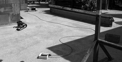
6 Quick start of the ZipLevel Open the bottom protective cap of the basic unit and remove the measuring module. Lay the basic unit on the floor with the back facing down. Slowly pull a sufficient length of line off the cable reel. The altitude will be transferred from the basic unit to the measuring module. Switch the measuring module on with the ON/OFF-key and put the unit with its back or base on the required place of reference. When the display is ready, you will hear 2 short audible bleeps. Press the ZERO-key for 2 seconds. Keep the measuring module steady until the figure zero appears on the display. The appliance has now been set. ADVICE: If the basic unit gets moved, the measuring module needs to be set at the place of reference again. Base Back facing down! Back
7 Quick start of the ZipLevel Give a place of reference to the measuring module (press ZERO-key) and move it to a different height. The appliance shows the difference in height between the place of reference and the measuring point. Now you can hold the appliance against any point and it always shows you the current height towards the place of reference. Always use the measuring module with the side, which was used to set ZERO. Do not change from one locating side to another without setting to ZERO again. If you want to find out the height between floor and ceiling set the appliance to ZERO with its back or bottom side on the floor. Then hold the top, base or back to the ceiling in order to measure. Manually add the height (8,8 cm) or thickness (5,0 cm) of the measuring module to the shown data. Take into account whether you are working with protective cover or not! This feature can also be done automatically with the ADDERfunction (pp ). Typical uses: ZipLevel measuring point reference point
8 Keys and functions ON/OFF With this key you switch the unit on and off. If no key has been pressed or the measuring module has not been moved within 4 minutes, the unit will switch itself off automatically. After 3 minutes without any activity the unit will sound a warning by giving 2 long bleeps. HOLD The HOLD-function is used where you have problems reading the display or where you intend to keep the measured data. The function can be switched on and off by shortly pressing the HOLD-key. Measuring and keeping of the data (see drawing p. 7): 1) First you set the unit at the required point with the ZERO-key. 2) Shortly press the HOLD-key as long as the measuring module is still being moved. The unit will then give a series of bleeps. 3) Move the measuring module to the place where you intend to measure. 4) Wait until the unit has stabilized and therefore no more bleeps are audible. 5) Retrieve the measuring module. The data of the remote point will be kept on the display. Shortly press HOLD again to leave this function.
9 Examples for the HOLD-function: 2. Press HOLD 1. ZERO ZERO Press the ZERO-key for 2 seconds in order to make the present height (location of the measuring module) the point of reference. The unit must not be moved in this process! 3 m New level of reference Level of reference When set zo zero at the top - 3 m will be shown at the bottom
10 SCALE With this you choose the required measurements in millimetres, centimetres or meters. Press the SCALE-key for 2 seconds and hold. Now the gauges the bottom right of the display will change. Release the key once the required measurement appears. The measurement for millimetres is not indicated, cm and m appear on the display. RES The ZipLevel is featured with a choice of 3 display accuracies. Press the RES-key for 2 seconds and keep it pressed in order to choose the required resolution. Release the RES-key once the required resolution is shown. Your choice is stored now up to next accuracy change. 0,2 cm: for highest accuracy needs more time to stabilize 0,5 cm: for medium accuracy needs less time for stabilization 1 cm: for rough measuring quick stabilizing of the results 10
11 REC The ZipLevel can also be used for different calculations and shows an average, minimum and maximum. 1) Press the REC-key for 2 seconds. The word REC appears on the left side of the display. 2) Stabilize the measuring module on the first measuring point and shortly press HOLD to keep the data. After that you hear a series of bleeps. Wait until these are finished before you move the module to the next measuring point. 3) Shortly press the REC-key to show the average as well as the highest and bottom rate of the series of measurements. After shortly pressing the REC-key the letters AVG (average), MIN and MAX will be shown on the display. 4) Press the REC-key for 2 seconds to leave this function. The calculated figures remain saved until you press the HOLD-key after recalling the REC-function. Value display 11
12 MARK With the MARK-function you can produce tones to indicate the following states: a) a chosen height, b) height within a defined scope or c) height beyond a defined scope. 1) Start of this function: Get the measuring module into the required height and press the MARK-key for 2 seconds. Keep the unit steady until double lines for the scope are blinking on the display and choose a), b) or c). a) Produce a tone at a chosen height: Shortly press MARK and keep the unit steady to set up the tone. b) Produce a tone within a defined scope: Move the measuring module half a scope under the chosen height. Shortly press MARK and hold the unit steady to set up the tone. c) Produce a sound beyond a defined scope: Move the measuring module half a scope above the chosen height. Shortly press MARK and hold the unit steady to set up the tone. Advice: If you want to leave the MARK-function early, shortly press MARK and ON/OFF at the same time. 12
13 Define scopes: a) Tone at a certain height: for accurate levelling ZipLevel MARK Tone b) Tone within a scope: for less accurate levelling No tone Scope Tone MARK c) Tone beyoned a scope: for rough levelling No tone Continuous tone MARK Scope No tone Bleeping tone 13
14 CAL The appliance has been calibrated at the factory. Please only calibrate, in case the measuring results are wrong or the letters CAL are blinking on the display. A benchmark of m above the base unit is important for the gauging. It will be best to use the sensing device to gauge the appliance (only with ZipLevel Pro 35). Calibrating the ZipLevel: 1) Put the basic unit on its back onto a level surface and switch the measuring module on. 2) Lay the measuring module on its base or back next to the basic unit. Press the CAL-key for 2 seconds. 3) When (0) is blinking on the display, shortly press CAL. 4) When (1.219) is blinking on the display, raise the measuring module to a height of m above the basic unit and press CAL again. The measuring module has to be held stable during the process. The sensing device (only with ZipLevel Pro 35) or a measuring marking should be used as a calibration device. 5) When the display stops blinking and shows m the appliance is recalibrated. Advice: You can leave the calibration function at any time without calibrating! For that you press the CAL-key for 2 seconds. 14
15 Calibration in 3 steps: Step 1: Step 2: Step 3: ZipLevel Lay the measuring module on its base or back next to the basic unit and press the CAL-key again. (0) is blinking on the display. Press CAL again. (121.9) is blinking on the display. Lift to a height of m and press CAL again. Hold steadily during the process. Then (121.9) is shown on the display. Step 1 Step 2 Step 3 1,219 m 15
16 ADDER (add): To carry out accurate measurements indoors, the ADDER-function automatically adds the height, respectively thickness of the measuring module on the measured data. Advice about the protective cover (only with ZipLevel Pro 35): You need to state whether you are working with or without protective cover ( Boot on / Boot off ). Press HOLD to keep the data. Then press CAL-key for 2 seconds and hold. Display alternately shows bon and boff. Release at either Boot on or Boot off. Press HOLD again to leave this function. This choice is saved for further measuring! Access to the ADDER-funktion: 1) Set the required point of reference with the ZERO-key. 2) Press HOLD and move the measuring module to the required measuring point (e.g. from the floor to the ceiling). You hear short bleeps. Keep the measuring module stable on the measuring point. The bleeps will stop when the figure is configured. 3) Now press the MARK-key to add the height of the measuring module or press the REC-key for 2 seconds to add the thickness of the measuring module. Press the HOLD-key to leave the function. 16
17 Boot on / Boot off : ZipLevel HOLD CAL 2 seconds Choose Boot on or Boot off! ADDER-function: MARK + Height REC + Thickness 8,8 cm or 9,4 cm with cover cm or 5,6 cm with cover 2. HOLD 2. HOLD 1. ZERO ZERO Base Back Base Back 1. 17
18 TIPS FOR USERS 1) Check the point of reference often when carrying out critical/serious levelling jobs or press ZERO often at the point of reference. (CAL is not necessary for levelling!) Hold the height differences between line, basic unit and measuring module as low as possible. 2) If possible, avoid high differences in temperature between line and measuring module (e.g. sun and shade). 3) Avoid unnecessary kinks over objects. 4) Avoid pulling hard, whipping or stepping on the line without checking the point of reference or setting to zero. 5) The display blinks 8888 at use beyond the specified altitude range. Beyond the temperature range under -30 C or over +70 C CAL is continuously shown. 6) As the ZipLevel shows the last carried out function when switched on, please make sure that you leave the function after every measuring. Hold the relevant key for 2 seconds and you leave the function. 7) Wischen Sie bei matschigen Bedingungen die Messleitung vor dem Aufwickeln mit einem Tuch ab. 8) Does respectively CAL show up, press the ZERO-key as soon as possible respectively calibrate the appliance. 18
19 Technical facts Vertical measuring range 12 m (6 m over and under the basic unit) Horizontal measuring range + 35 m ZipLevel Pro 35 (70 m Ø) + 25 m ZipLevel 25 (50 m Ø) Levelling precision 3 mm Height-measuring accuracy 0,2 % of the shown data up to 3 m, resp. 0,35 % of the shown data over 3 m Scale/measurements Saving of data and setting mm, cm, m unlimited, even without battery Shock-resistance dropping test on concrete Measuring module 1,5 m Basic unit 0,9 m Water resistance Rain proof; must not be immersed Operating time 9 V Block 60 operating hours Weight 3,5 kg Working an storing temperature -30 C C 19

20 Service- and shipping address: Umarex GmbH & Co. KG Laserliner Möhnestraße 149, D Arnsberg, Germany Tel.: , Fax: -333 UMAREX GmbH & Co. KG Laserliner Donnerfeld 2 D Arnsberg, Germany Tel.: , Fax:
MetalliFinder Pro DE 02 GB 06 NL 10 DK 14 FR 18 ES 22 IT 26 PL 30 FI 34 Manual_MetalliFinder-Pro_Rev.0909.indd Abs
 DE 02 06 NL 10 DK 14 FR 18 ES 22 IT 26 PL 30 FI 34 a b c d e f 3 2 1 5 4 9 7 8 6 Operating elements a LED Measuring centre b LED Current (AC) found c Set button: Change over material types iron pipes,
MultiMeter-Pocket CAT III 1000 V
 02 10 18 26 34 42 50 58 66 74 82 DE GB NL DK FR ES IT PL FI PT SE AC DC AC DC CAT III 1000 V 90 98 106 114 122 130 138 146 154 162 170 NO TR RU UA CZ EE LV LT RO BG GR ! Read the operating instructions
SensoMaster Bedienungsanleitung Operating instructions Gebruiksaanwijzing Betjeningsvejledning Mode d emploi
 DE GB NL DK FR Bedienungsanleitung Operating instructions Gebruiksaanwijzing Betjeningsvejledning Mode d emploi 3-20 21-38 39-56 57-74 75-92 028.80 / Rev 0908 2 General Description The SensoMaster is designed
+20 (6m) 200 (60m) CIRCLE. Measurement Module* Unipod. Base Unit. Cord. SINGLE SET-UP RANGES -20 (6m) *Zero at any reference within range
 200 (60m) CIRCLE. Measurement Module* Unipod. Base Unit. Cord. SINGLE SET-UP RANGES -20 (6m) *Zero at any reference within range") ZIPLEVEL SYSTEM CONCEPT INTRODUCTION 200 (60m) CIRCLE +20 (6m) Unipod Measurement Module* You re about to enter an exciting new labor saving world of elevation measurement and leveling. The ZIPLEVEL PRO-2000
ZIPLEVEL SYSTEM CONCEPT INTRODUCTION 200 (60m) CIRCLE +20 (6m) Unipod Measurement Module* You re about to enter an exciting new labor saving world of elevation measurement and leveling. The ZIPLEVEL PRO-2000
Multi-Channel In-Out Thermometer with Cable Free Sensor and RF Clock
 Multi-Channel In-Out Thermometer with Cable Free Sensor and RF Clock MAIN FEATURES: MAIN UNIT GB MODEL: RMR182 USER'S MANUAL INTRODUCTION Congratulations on your purchase of the RMR182 Multi- Channel In-Out
A510S Operation Manual
 A510S Operation Manual REV 1.1 1 Table of Contents 1 General Information 1-1 Description 1-2 Potential Operational Hazards 1-3 Technical Specifications 1-4 Instrument Overview 1-5 Function Summary 2 How
CCR24T CCR24R. User s Guide WIRELESS TRANSMITTER SYSTEM WARRANTY SERVICE CARD WARRANTY CARD
 WARRANTY SERVICE CARD WARRANTY CARD PRODUCT NAME Wireless Transceiver System PERIOD MODEL NAME CCR24GEN YEAR PURCHASE DATE.. 200_ From the date of WARRANTY PERIOD.. 200_ purchase. CUSTOMER S ADDRESS :
ENGLISH VERSION. CITO Rule Puller. Operation & Maintenance Manual. CITO FormLine
 ENGLISH VERSION CITO Rule Puller Operation & Maintenance Manual CITO FormLine 1 Index Index Field of Application 3 Product Appearance 3 Product Description 4 Product Dimensions & Weight 4 Product Components
UVA/B Light Meter. Instruction Manual. UVA/B Light Meter Copyright 2009 by Sper Scientific ALL RIGHTS RESERVED. Printed in the USA
 UVA/B Light Meter 850009 Copyright 2009 by Sper Scientific ALL RIGHTS RESERVED UVA/B Light Meter 850009 Instruction Manual Printed in the USA The contents of this manual may not be reproduced or transmitted
Laser LA-4P. Operating instructions
 Laser LA-4P GB Operating instructions A 1 2 3a 5 3c 3b 3a 4 11 11 6 10 7 14a 14b 14c 12 9 8 B C 2. 1. D E F Ø 50mm - 115 mm Ø 2-4,5 G I K s > 6m > 20ft L M N P1 Q O 13 P2 GB Operating instructions The
AC-SENSOR 63 UND 250 AC-SENSOR 63 AND 250
 AC-SENSOR INSTALLATIONSANLEITUNG INSTALLATION GUIDE DE EN AC-SENSOR 63 UND 250 INSTALLATIONSANLEITUNG AC-SENSOR 63 AND 250 INSTALLATION GUIDE 1 Scope of delivery Check the delivery for completeness and
Bedienungsanleitung Instruction Manual. testo 815 Sound Level Meter
 Bedienungsanleitung Instruction Manual testo 815 Sound Level Meter de en 18 General Information General Information Please read this documentation through carefully and familiarise yourself with the operation
AC Active Transmitter Combiner 8:1
 Active Transmitter Combiner 8:1 AC 3000 Bedienungsanleitung Instructions for use Notice d emploi Istruzioni per l uso Instrucciones para el uso Gebruiksaanwijzing 8 Bedienungsanleitung...3 Instructions
CM605. User Manual AC/DC LOW CURRENT CLAMP-ON METER ENGLISH
 AC/DC LOW CURRENT CLAMP-ON METER CM605 ENGLISH User Manual Statement of Compliance Chauvin Arnoux, Inc. d.b.a. AEMC Instruments certifies that this instrument has been calibrated using standards and instruments
Top spin Nr /
 Top spin Nr. 1840 0000 / 1840 1000 Bedienungsanleitung 21-6680 28052014 / A Made in Germany Ideas for dental technology Top spin Nr. 1840 0000 / 1840 1000 Contents 1. Introduction...2 1.1 Symbols...2 2.
OPERATION & SERVICE MANUAL FOR FC 110 AC POWER SOURCE
 OPERATION & SERVICE MANUAL FOR FC 100 SERIES AC POWER SOURCE FC 110 AC POWER SOURCE VERSION 1.3, April 2001. copyright reserved. DWG No. FC00001 TABLE OF CONTENTS CHAPTER 1 INTRODUCTION... 1 1.1 GENERAL...
Geotagger N3. User Manual (V1.0) Revised by Geosolve.be (Pol F. Gillard) with personal updates and help. Solmeta Technology Co.
 Revised by Geosolve.be (Pol F. Gillard) with personal updates and help. Solmeta Technology Co.") Geotagger N3 User Manual (V1.0) Revised by Geosolve.be (Pol F. Gillard) with personal updates and help Solmeta Technology Co., Ltd Copyright 2011 Solmeta Technology Co., Ltd. All Rights Reserved 1 Contents
Geotagger N3 User Manual (V1.0) Revised by Geosolve.be (Pol F. Gillard) with personal updates and help Solmeta Technology Co., Ltd Copyright 2011 Solmeta Technology Co., Ltd. All Rights Reserved 1 Contents
Copyright Graupner/SJ GmbH. Manual. mz-4 2 channel HoTT 2,4 GHz transmitter No. S1031
 Copyright Graupner/SJ GmbH EN Manual mz-4 2 channel HoTT 2,4 GHz transmitter No. S1031 Index Introduction... 4 Service Centre... 4 Intended use... 5 Package content... 5 Technical Data... 5 Symbols explication...
Instruction Manual TS
 DIGITAL COATING THICKNESS GAUGE mismatched or damaged, don t hesitate to contact SAUTER GmbH promptly. - Digital coating thickness tester - 9V battery - - Standard sheet gauge - Iron base material for
Visit us at
 testo 816 Sound Level Meter Instruction Manual 99 Washington Street Melrose, MA 02176 Phone 781-665-1400 Toll Free 1-800-517-8431 Visit us at www.testequipmentdepot.com 20 General Information General Information
Professional UHF Rechargeable Wireless Microphone System POWER ON/OFF BATTERY CHARGE. Green Light (Full) Better Music Builder DOWN VOLUME
 Better Music Builder DOWN VOLUME") Green Light (Full) KARAOKE Professional UHF Rechargeable Wireless Microphone System VM-93C Operating Instructions UHF Frequency 64 Selectable POWER ON/OFF CHARGE Better Music Builder VM-93C CHARGER UHF
Green Light (Full) KARAOKE Professional UHF Rechargeable Wireless Microphone System VM-93C Operating Instructions UHF Frequency 64 Selectable POWER ON/OFF CHARGE Better Music Builder VM-93C CHARGER UHF
AC Active Transmitter Combiner 8:1
 Active Transmitter Combiner 8:1 AC 3000 Bedienungsanleitung Instructions for use Notice d emploi Istruzioni per l uso Instrucciones para el uso Gebruiksaanwijzing 8 Active Transmitter Combiner 8:1 Instructions
INSTRUCTION MANUAL UTL260
 INSTRUCTION MANUAL UTL260 1-800-547-5740 Fax: (503) 643-6322 www.ueitest.com email: info@ueitest.com Introduction The UTL260 has all the features and measurement functions that appliance technicians need.
MODEL SETUP & OPERATION MANUAL DOVETAIL JIG FEATURES SPECIFICATIONS
 SETUP & OPERATION MANUAL FEATURES Male and female dovetail joints are cut simultaneously, to ensure perfectly matched dovetail joints. Side stops provided, allow repeated precise dovetail joint cutting
32 CHANNEL SELECTABLE CH MHZ DOWN VOLUME
 KARAOKE Professional UHF Wireless Microphone System VM-92U Operating Instructions UHF Frequency 64 Selectable Better Music Builder UHF MIC WIRELESS SYSTEM VM-92U 32 CHANNEL SELECTABLE 248 13.10 CH MHZ
OB1U INSTALLATION INSTRUCTIONS. Interactive Flat Panel Over White Board Mount
 INSTALLATION INSTRUCTIONS Interactive Flat Panel Over White Board Mount Spanish Product Description German Product Description Portuguese Product Description Italian Product Description Dutch Product Description
INSTALLATION INSTRUCTIONS MSP-SPFB (PFB-2000S) Plasma Floor Stand
 Plasma Floor Stand") INSTALLATION INSTRUCTIONS MSP-SPFB (PFB-2000S) Plasma Floor Stand Chief s Plasma Floor Stand is a safe, stable, easy-toinstall modular design solution for digital signage and presentations. Ideal where
INSTALLATION INSTRUCTIONS MSP-SPFB (PFB-2000S) Plasma Floor Stand Chief s Plasma Floor Stand is a safe, stable, easy-toinstall modular design solution for digital signage and presentations. Ideal where
GMINI 300PE AM/FM/Shortwave Radio OWNER S MANUAL
 GMINI 300PE AM/FM/Shortwave Radio OWNER S MANUAL Grundig Radio Line By www.etoncorp.com Grundig Radio Line By DO YOU NEED HELP? Contact Us Etón Corporation 1015 Corporation Way Palo Alto, CA 94303, USA.
Magnetic Inductive Flow Sensor induq
 Operating manual (Translation) Operating manual... page 1-16 Magnetic Inductive Flow Sensor induq Series VMZ SIKA Ba_VMZ_en 10/2014. Please keep this operating manual for future reference. If the device
WS-7136U Wireless 433 MHz Temperature Station. Instruction Manual
 WS-7136U Wireless 433 MHz Temperature Station Instruction Manual TABLE OF CONTENTS Topic Page Inventory of Contents 3 Additional Equipment 4 Quick Setup 5-9 Detailed Setup Guide Battery Installation 10-12
KEEP FOR FUTURE REFERENCE STOWAWAY TILT TABLE READ ALL INSTRUCTIONS AND WARNINGS BEFORE USING THIS TABLE
 KEEP FOR FUTURE REFERENCE INSTRUCTIONS International Version P.O. Box 368 908 West Main Laurel, MT USA 59044 phone 800-548-7341 phone 406-628-8231 fax 406-628-8354 MODEL NUMBER: STT1 SERIAL NUMBER: (please
MetalliScanner 6.0 Components
 MetalliScanner 6.0 Components 1. Mode Switch 2. Calibration Switch 3. Crosshairs 4. Liquid Crystal Display 5. Battery Compartment LCD Components 1. Depth Bars 2. Depth Numbers 3. Magnetic Icon 4. Low Battery
TRACEABLE RADIO-SIGNAL REMOTE THERMOMETER INSTRUCTIONS
 TRACEABLE RADIO-SIGNAL REMOTE THERMOMETER INSTRUCTIONS SPECIFICATIONS Display Main unit: two-line 1" LCD Remote unit: 3 /8" LCD Temperature Main unit IN range: 9.9 to 158.0 F ( 9.9 to 70.0 C) Main unit
MPA-9000 Universal Ceiling Projector Mount Kit
 I N S T R U C T I O N M A N U A L Universal Ceiling Projector Mount Kit The Universal Ceiling Projector Mount provides a unique, simplified method of ceiling mounting your inverted projector. This low
WS-7212NU Wireless 433 MHz Weather Station. Instruction Manual
 WS-7212NU Wireless 433 MHz Weather Station Instruction Manual TABLE OF CONTENTS Topic Page Inventory of Contents 3 Additional Equipment 4 Quick Setup Guide 5-9 Function Keys 5 Detailed Set-up Guide 10-15
This manual applies to the WT-RC-Ex receiver when used to locate all makes and models of 22 Hz and Wavetrak coded transmitters.
 This manual applies to the WT-RC-Ex receiver when used to locate all makes and models of 22 Hz and Wavetrak coded transmitters. The Wavetrak WT-RC-Ex receiver kit comes with the following pieces of equipment:
WS-9006U Wireless Temperature Station
 WS-9006U Wireless Temperature Station Instruction Manual RF reception indicator Outdoor Temperature Indoor Temperature Time Outdoor Temperature Sensor TX43U MIN/MAX/+ Button CF / SET Button FEATURES: Four
CRCODE-202. Mechanical Lock. Instruction and Programming Manual. Before Installing:
 CRCODE-202 Mechanical Lock Instruction and Programming Manual Before Installing: 1. Please read the instructions carefully to prevent missing important steps. *Note: Improper installations may result in
Kittec -CBG Gas. U s e r s M a n u a l
 Kittec -CBG Gas U s e r s M a n u a l Contents Page Table of contents 1 About this Users Manual 2 Use of the kiln 2 Safety 2 Safety tips 3 Installation and Operation 4 Storage and transport 4 Installation
INSTRUCTION MANUAL MODEL SAS RS-7 LASER DISTANCE METER
 INSTRUCTION MANUAL MODEL SAS RS-7 LASER DISTANCE METER KEYS, DISPLAYS AND FUNCTIONS GENERAL SAFETY RULES! DANGER! Do not aim light at persons or animals. Do not stare into the laser light source. Laser
f i r e - p a r t s. c o m
 Model: CON 1001-1 INSTALLATION AND OPERATING INSTRUCTIONS SINGLE-FUNCTION WIRELESS REMOTE CONTROL SYSTEM FOR OPERATING VALVES WITH ON/OFF LATCHING SOLENOIDS IF YOU CANNOT READ OR UNDERSTAND THESE INSTALLATION
Ior DIGITAL LEAKAGE CLAMP TESTER MCL-400IR INSTRUCTION MANUAL
 Ior DIGITAL LEAKAGE CLAMP TESTER MCL-400IR INSTRUCTION MANUAL Thank you very much for selecting our model MCL-400IR Ior Leakage Clamp Tester. Before use the instrument, read this instruction manual completely
Beaming Optical Length Tester (BOLT)
") O.W.L. MANUFACTURER OF QUALITY OPTICAL FIBER TEST EQUIPMENT OPTICAL WAVELENGTH LABORATORIES Beaming Optical Length Tester (BOLT) Operations Manual Version 1.0 November 8, 001 OWL Part BOLT-1 TABLE OF CONTENTS
O.W.L. MANUFACTURER OF QUALITY OPTICAL FIBER TEST EQUIPMENT OPTICAL WAVELENGTH LABORATORIES Beaming Optical Length Tester (BOLT) Operations Manual Version 1.0 November 8, 001 OWL Part BOLT-1 TABLE OF CONTENTS
AC/DC Current Oscilloscope Probe Model SL261
 AC/DC Current Oscilloscope Probe Model SL261 USER MANUAL I ZERO 100 mv/a 10 mv/a OFF Statement of Compliance Chauvin Arnoux, Inc. d.b.a. AEMC Instruments certifies that this instrument has been calibrated
WEATHER FORECAST MULTI-CHANNEL IN-OUT THERMOMETER WITH CABLE FREE SENSOR AND RADIO CONTROLLED CLOCK MAIN FEATURES: MAIN UNIT INTRODUCTION
 WEATHER FORECAST MULTI-CHANNEL IN-OUT THERMOMETER WITH CABLE FREE SENSOR AND RADIO CONTROLLED CLOCK MODEL: BAR888A USER S MANUAL MAIN FEATURES: MAIN UNIT GB INTRODUCTION Congratulations on your purchase
CMA-455 Suspended Ceiling-Tile Reinforcing Kit
 INSTALLATION INSTRUCTIONS CMA-455 Suspended Ceiling-Tile Reinforcing Kit The provides a sturdy support for LCD/DLP hanging brackets (and certain other products) when installing these products in a suspended
Radio System Strobe Wizard Plus Freemask
 Radio System Strobe Wizard Plus Freemask User manual Translation of the original German user manual Doc. No.: 900.0509.00 Version: 09/2017 Contents Information about this manual and about the manufacturer...
Merloni Elettrodomestici. Technical Fitting Manual FRIDGE. Language Issue/Edition Page GB /
 GB 99-11-03/01 1-38 Index 1 CONFORMITY OF APPLIANCE 3 2 MAIN ASSEMBLY TYPES 3 2.1 Under worktop 3 2.2 Double door 10 2.3 Combined 14 2.4 Single door Fridge or single door Freezer 19 2.5 Combined free-standing
AC/DC Current Probes Model MR411 Model MR521
 AC/DC Current Probes Model MR411 Model MR521 USER MANUAL OL OL ON ON 600V CAT III - 600A 600V CAT III - 1500A 60A 600A OFF 150A 1500A OFF! OUTPUT: 600A: 1 mv/a 60A: 10 mv/a! OUTPUT: 1500A: 1 mv/a 150A:
Plasma Presenters Cart (PPC-2000)
") I N S T R U C T I O N M A N U A L (PPC-2000) The (PPC) is designed to assist the presenter in showrooms, boardrooms, and trade show exhibits. The PPC provides agile mobility for screens weighing up to
I N S T R U C T I O N M A N U A L (PPC-2000) The (PPC) is designed to assist the presenter in showrooms, boardrooms, and trade show exhibits. The PPC provides agile mobility for screens weighing up to
PHV RO High Voltage Passive Probe. Instruction Manual
 PHV 1000-3-RO High Voltage Passive Probe Instruction Manual Copyright 2012 PMK GmbH All rights reserved. Information in this publication supersedes that in all previously published material. Specifications
WS-7220U-IT 915 MHz Wireless Weather Station. Instruction Manual
 WS-7220U-IT 915 MHz Wireless Weather Station Instruction Manual 1 TABLE OF CONTENTS Introduction..3 Inventory of Contents 4 Quick Set Up 4 Detailed Set Up 4-5 Battery Installation....4-5 12 or 24 Hour
Digital Anemometer
 THE WORLD OF WEATHER DATA - THE WORLD OF WEATHER DATA - THE WORLD OF WEATHER DATA Instruction for Use 021404/07/04 Digital Anemometer 4.3406.00.000 ADOLF THIES GmbH & Co. KG Hauptstraße 76 37083 Göttingen
15mm Solid European Droploc Oak Fitting Guide & Warranty Information
 15mm Solid European Droploc Oak & Warranty Information Introduction Congratulations on your purchase of your brand new Timba Floor 15mm European Solid Oak Flooring. Prior to installation please examine
MS2302. Digital Earth Resistance Tester
 MS2302 Digital Earth Resistance Tester OPERATING INSTRUCTION PRECISION MASTECH ENTERPRISES CO. Unit 8, 21/FL, Yen Sheng Center, 64 Hoi Yuen Road, Kwun Tong, Kowloon, Hong Kong. Tel: 852-23430007 Fax:852-23436217
DETECTORS. USER MANUAL
 DETECTORS www.noktadetectors.com USER MANUAL INTRODUCTION Thank you for choosing and purchasing our 109 Deep Pro detector. Manufacturing high-tech metal detectors since 2001, Nokta Detectors has played
KPS Turbidity Meter User s Manual
 KPS Turbidity Meter User s Manual Küppers Elektromechanik GmbH Quality system certified to DIN ISO 91 Contents Product description... page 3 Technical data... page 3 Dimensions... page 4 Getting started...
1/4in. SHEET PALM SANDER
 1/4in. SHEET PALM SANDER OPERATING INSTRUCTIONS SPECIFICATIONS ITEM# 151608 Voltage: Max. output: No load speed: Cord: 120V ~ 60Hz 180W 14000 RPM 6 feet (2m) Dust-Sealed On/off Switch Dust Extraction Adaptor
ProHead. User s Guide
 ProHead User s Guide 2Profoto ProHead Profoto ProHead Thank you for choosing Profoto. Thanks for showing us your confidence by investing in a ProHead unit. For more than four decades we have sought the
USER'S MANUAL DMR-4350
 USER'S MANUAL DIGITAL MULTIMETER DMR-4350 CIRCUIT-TEST ELECTRONICS www.circuittest.com TABLE OF CONTENTS SAFETY Safety Information...................................... 2 Safety Symbols........................................
INSTALLATION INSTRUCTIONS Plasma Floor Stand (PFB-2000SB)
") INSTALLATION INSTRUCTIONS Plasma Floor Stand (PFB-2000SB) Chief s Plasma Floor Stand is a safe, stable, easy-toinstall modular design solution for digital signage and presentations. Ideal where wall or
INSTALLATION INSTRUCTIONS Plasma Floor Stand (PFB-2000SB) Chief s Plasma Floor Stand is a safe, stable, easy-toinstall modular design solution for digital signage and presentations. Ideal where wall or
Laser Distance Finder Extech DT500
 User Guide Laser Distance Finder Extech DT500 Introduction Congratulations on your purchase of the Extech Model DT500 Laser Distance Finder. This meter measures Distance up to 70m (230 ) and calculates
ApexDesk Assembly Guide
 ELECTRIC HEIGHT-ADJUSTED SIT TO STAND DESK ApexDesk Assembly Guide REV-1507C Table of Contents CAUTION, USE & LIABILITY... 3 PARTS & HARDWARE LIST... 4 PARTS / COMPONENT DIAGRAMS... 5 ASSEMBLY INSTRUCTIONS...
User guide ProHead Plus
 User guide ProHead Plus For other languages visit: /support ProHead Plus 2 Congratulations on your new Profoto product! Thanks for showing us your confidence by investing in a ProHead unit. For more than
Heart Rate 1. Calories 3. Current Altitude Parts. Set Home Altitude 5. Clock. Ascent% 7. Average Display. Date. Maximum Speed 13
 - English - Content Heart Rate 1 Introduction Reset Trip Data 31 Set Smart EL Calories 3 Unit 17 Enter Setting Mode Power Calibration 47 Current Altitude Parts 19 Set Clock 33 Mode / Sub Mode Functions
OPERATING INSTRUCTIONS
 OPERATING INSTRUCTIONS Rotary Microtome CUT 4062 / CUT 5062 / CUT 6062 CUT 6062 illustrated above INS1000GB 2012-01-06 Instructions CUT4062 / CUT 5062 / CUT 6062 2 CONTENTS 1. INTENDED USE... 4 2. SYMBOLS...
IMPORTANT: Read Before Using. Operating/Safety Instructions 8601-RL
 IMPORTANT: Read Before Using Operating/Safety Instructions 8601-RL 3 1 2 7 5 6 8 6 4-2- General Safety Rules! DANGER LASER RADIATION. AVOID DIRECT EYE EXPOSURE. DO NOT stare into the laser light source.
Fit IPL-R. Instruction Manual (Rev06 - Jun 2018; Firm. Vers.11)
") Fit IPL-R Instruction Manual (Rev06 - Jun 2018; Firm. Vers.11) WARNING! The user of this instrument must be trained to the use of power lasers and associated risks. LaserPoint is in no way liable for any
Fit IPL-R Instruction Manual (Rev06 - Jun 2018; Firm. Vers.11) WARNING! The user of this instrument must be trained to the use of power lasers and associated risks. LaserPoint is in no way liable for any
GENERATION AHEAD TECHNOLOGY
 GENERATION AHEAD TECHNOLOGY I. Introduction II. About the SmartPro Gem-Eye I III. IMPORTANT NOTICE 1. GETTING STARTED 2. PERFORMING A TEST 3. READING TEST RESULTS 4. TAKING CARE CONTENTS 04 05 10 12 26
GAS HOT GLUE GUN PHKPG 150 A1. Operating and safety instructions IAN
 GAS HOT GLUE GUN PHKPG 150 A1 Operating and safety instructions IAN 285747 14 1 2 13 3 4 5 12 11 10 9 6 7 8 A B C 1. 3. 2. Table of contents 1. Scope of delivery / parts list... 04 Description of the parts...04
PORTROD WALL MOUNTED HEIGHT ROD
 PORTROD WALL MOUNTED HEIGHT ROD USER INSTRUCTIONS P/N UMPORTROD Rev 1-052112 1 PORTROD Thank you for your purchase of this Health o meter Professional product. Please read this manual carefully, and keep
Manual Pull-Down Screen. Elite Manual Series USER S GUIDE MATTE WHITE. Rev. 1.3
 Manual Pull-Down Screen Elite Manual Series USER S GUIDE MATTE WHITE Pre-installation 1. Carefully unpack the screen 2. Always handle the screen on a clean and level surface. a: Vertical hooks suspend
GammaPAT MI 3311 Short instructions Ver. 1.4, Code no
 GammaPAT MI 3311 Short instructions Ver. 1.4, Code no. 20 751 626 Distributor: Manufacturer: METREL d.d. Ljubljanska cesta 77 1354 Horjul Slovenia E-mail: metrel@metrel.si http://www.metrel.si 2010 METREL
OPERATING MANUAL SESAM 800 MOBILE TAIL LIFT EN -D0
 OPERATING MANUAL SESAM 800 MOBILE TAIL LIFT 942913-000 EN -D0 2 (16) Table of Contents 1 Introduction 3 2 Scope 3 3 Service 3 4 Maintenance 4 5 Technical Specifications 4 6 Short Description of the System
Heiland electronic GmbH TD / TD1 / TD2. B&W-Densitometers. USERS MANUAL Version 5
 Heiland electronic GmbH TD / TD1 / TD2 B&W-Densitometers USERS MANUAL Version 5 2 Table of Contents 1. GENERAL INFORMATION...4 2. SAFETY REGULATIONS...5 3. AREA OF APPLICATIONS...5 4. INSTRUMENT DESCRIPTION...6
Contents. English 1. French 29. Spanish. FEATURES: The Temperature Station
 Contents Language Page English 1 French 29 Spanish Topic Page Inventory of Contents 2 Features 3 Setting Up Battery Installation 7 Function keys 9 LCD Screen and Settings 11 Manual Settings 13 Viewing
DUNHAM & MORROW By Schonstedt Instrument Company Tel: Fax:
 DUNHAM & MORROW By Schonstedt Instrument Company Tel: 304-724-4790 Fax: 304-724-4725 dml@schonstedt.com www.magneticlocator.com 1 Quick Start Instructions 1. Make yourself magnetically clean. Typical items
V00029KX READ ALL OF THE FOLLOWING INSTRUCTIONS BEFORE REMOVING CABINET FROM SKID
 READ ALL OF THE FOLLOWING INSTRUCTIONS BEFORE REMOVING CABINET FROM SKID Net-Verse D-Type Cabinets Tool List 10mm Socket Wrench 122mm (48 ) Level 19mm Wrench 8mm Hex Drive T25 Torx driver Net-Verse D-Type
Laser Distance Finder Extech DT500
 User Guide Laser Distance Finder Extech DT500 Introduction Congratulations on your purchase of the Extech Model DT500 Laser Distance Finder. This meter measures Distance up to 70m (230 ) and calculates
Contents. Page English 1. French. Spanish. Reset of MIN/MAX records 915 MHz Reception Mounting Care and Maintenance Warranty Information
 Contents Language Page English 1 French Spanish WIRELESS 915 MHz TEMPERATURE STATION Instruction Manual TABLE OF CONTENTS Topic Page Inventory of Contents Features Setting Up Battery Installation Function
Manual Moisture determination scales PCE-MA 110
 PCE Americas Inc. 711 Commerce Way Suite 8 Jupiter FL-33458 USA Tel: 410-387-7703 Fax: 410-387-7714 info@pce-americas.com www.pce-instruments.com/us www.industrial-needs.com PCE Instruments UK Ltd. Units
COULISSE MOTION CM-01/02 TUBULAR MOTOR MANUAL CM-01/02. The easiest motorization for single roller blinds
 MANUAL CM-01/02 The easiest motorization for single roller blinds CM-01/02 Tubular motor The easiest motorization for single roller blinds WARNING Read the instructions carefully before assembling and
Detectores de metales y otros materiales digitales GMS120 bosch manual ingles
 1 2 3 4 10 9 8 5 6 G ss 0 7 PrM ofe12 ional GM 120 4 2 12 13 Pro 14 15 17 18 18 16 M ss0 G M ss0 5 A e a b c d f g h i j k 12 2 A e ns or 3x G 10 English English afety otes Read and observe all instructions.
PHV 1000-RO High Voltage Passive Probe. Instruction Manual
 PHV 1000-RO High Voltage Passive Probe Instruction Manual Copyright 2014 PMK GmbH All rights reserved. Information in this publication supersedes that in all previously published material. Specifications
Microwave Meter. Instruction Manual
 Microwave Meter 840046 Instruction Manual Microwave Meter 840046 Copyright 2009 by Sper Scientific ALL RIGHTS RESERVED Printed in the USA The contents of this manual may not be reproduced or transmitted
FlexProbe FLEXIBLE AC CURRENT PROBE. User Manual. FlexProbe ON OL 1000V CAT III 300A 3000A OFF
 I N S T R U M E N T S FLEXIBLE AC CURRENT PROBE FlexProbe 24-3001 ON OL 1000V CAT III 300A 3000A OFF FlexProbe 24-3002 E N G L I S H User Manual Statement of Compliance Chauvin Arnoux, Inc. d.b.a. AEMC
FitSpine R.E.D. 5YEAR. Inversion Table Assembly Instructions WA R R A N T Y
 R FitSpine R.E.D. Inversion Table Assembly Instructions TEETER HANG UPS 5YEAR WA R R A N T Y BEFORE YOU BEGIN: Review all steps before beginning assembly and read all precautions before using the inversion
WATERFLUX 3000 Quick Start
 WATERFLUX 3000 Quick Start Electromagnetic flowmeter The documentation is only complete when used in combination with the relevant documentation for the signal converter. KROHNE CONTENTS WATERFLUX 3000
AW 2x120 BALANCED POWER AMPLIFIER
 AW 2x120 BALANCED POWER AMPLIFIER Owner s Manual WARNING: To reduce risk of fire or electric shock, do not expose this appliance to rain or moisture. Verify line voltage before use. Do not remove cover.
AT Underground Cable/Pipe Locator System. Users Manual Mode d emploi Bedienungshandbuch Manuale d Uso Manual de uso Användarhandbok
 AT-3500 Underground Cable/Pipe Locator System Users Manual Mode d emploi Bedienungshandbuch Manuale d Uso Manual de uso Användarhandbok For detailed specifications and ordering info go to www.testequipmentdepot.com
WS-29 DUAL CHANNEL WIRELESS BELTPACK
 WS-29 DUAL CHANNEL WIRELESS BELTPACK USER MANUAL Issue March 2011 ASL Intercom BV DESIGNED AND MANUFACTURED BY: ASL INTERCOM BV ZONNEBAAN 42 3542 EG UTRECHT THE NETHERLANDS PHONE: +31 (0)30 2411901 FAX:
Dawson DDM190. Digital Multimeter User s Manual
 Dawson DDM190 Digital Multimeter User s Manual TABLE OF CONTENTS LIMITED WARRANTY AND LIMITATION OF LIABILITY... 3 Out of the Box... 3 Accessories.. Error! Bookmark not defined. Safety Information... 7
WIRELESS 915 MHz TEMPERATURE STATION Instruction Manual
 Contents Language Page English 1 French Spanish TABLE OF CONTENTS WIRELESS 915 MHz TEMPERATURE STATION Instruction Manual Topic Inventory of Contents Features Setting Up Battery Installation Function keys
MAGNETIC FIELD METER Operator s Manual
 Edition 4.4 September 2011 MAGNETIC FIELD METER 3000 Operator s Manual The MFM 3000 is a professional magnetic field instrument To make the best use of the instrument we recommend that you read this manual
Arlink 8000 Workstation
 Arlink 8000 Workstation Instructions for Assembly Introduction Basic Frame Assembly Worksurface Assembly Drawer and Power Beam Assembly Light Fixture and Shelves Worksurface Grounding Instructions Wrist
MSP-WRTIDSKY1 Light Weight Suspended Ceiling Kit for use with Island Display Skybox
 INSTALLATION INSTRUCTIONS MSP-WRTIDSKY1 Light Weight Suspended Ceiling Kit for use with Island Display Skybox The MSP-WRTIDSKY1 Light Weight Suspended Ceiling Kit provides a sturdy support for LCD displays
WIRELESS 915 MHz TEMPERATURE STATION Instruction Manual
 Contents Language Page English 1 French Spanish TABLE OF CONTENTS WIRELESS 915 MHz TEMPERATURE STATION Instruction Manual Topic Inventory of Contents Features Setting Up Battery Installation Function keys
ProfiScale MULTI Multimeter
 1,5 V 9V 200 mv 600 V 200 ma 1/10 A ProfiScale MULTI Multimeter en Operating instructions BURG-WÄCHTER KG Altenhofer Weg 15 58300 Wetter Germany Introduction Want the reassurance of knowing whether current
An Inclined Plane. Experiment OBJECTIVES MATERIALS
 Dual-Range Force Sensor An Inclined Plane Experiment 22 An inclined plane is a slanted surface used to raise objects. The sloping floor of a theater, a road over a mountain, and a ramp into a building
COND 200. Conductivity/TDS/Salinity Meter Operating instructions. Meas Cal. Hold Rcl Store. On Off Menu
 COND 200 Conductivity/TDS/Salinity Meter Operating instructions Meas Cal Hold Rcl Store On Off Menu 2 Table of Contents Page 1. Scope of delivery...4 2. System description...4 3. Connections...6 4. Display...6