Diode Applications 1
|
|
|
- Camilla Shields
- 6 years ago
- Views:
Transcription
1 Diode Applications 1
2 Explain and analyze the operation of both half and full wave rectifiers Explain and analyze filters and regulators and their characteristics Explain and analyze the operation of diode limiting and clamping circuits Explain and analyze the operation of diode voltage multipliers. Interpret and use a diode data sheet Troubleshoot simple diode circuits 2

3 AC to DC dc Circuit A ac Power Supply dc Circuit B Most circuits operate with dc supply. dc Circuit C 3
4 Basic Power Supply Principle Rectification Filtering Regulation(no ripple) Good power supplies (i.e. required switching techniques, zener regulation, etc) 4
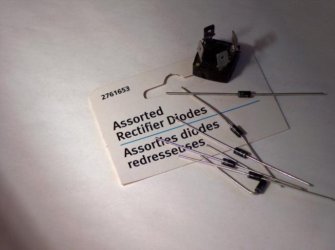
5 Diode Rectify The cathode makes this the positive end of the load ac Half-wave pulsating dc A series rectifier diode changes ac to dc. 5
6 Half-wave Rectifier A half wave rectifier(ideal) allows conduction for only 180 or half of a complete cycle. The output frequency is the same as the input. The average V DC or V AVG = V p / Proof this!!!! 6

7 Average voltage of half-wave rectifier 7
8 The effect of the barrier potential on the half-wave rectified output voltage is to reduce the peak value of the input by about 0.7 V. 8
9 Reverse Operation Peak inverse voltage(piv) is the maximum voltage across the diode when it is in reverse bias. PIV The diode must be capable of withstanding this amount of voltage. 9
10 TRANSFORMER Review 10

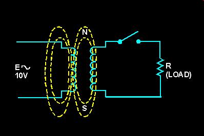
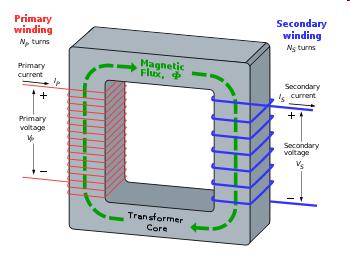
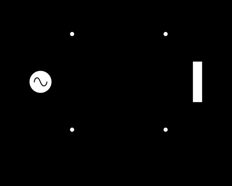
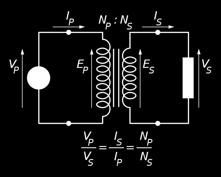
11 Transformer-Coupled Input Transformers are often used for voltage change and isolation. The turns ratio of the primary to secondary determines the output versus the input. The fact that there is no direct connection between the primary and secondary windings prevents shock hazards in the secondary circuit. 11
,")

12 VCT Volts center tapped (VCT) describes the voltage output of a center tapped transformer. For example: A 24 VCT transformer will measure 24 VAC across the outer two taps (winding as a whole), and 12VAC from each outer tap to the center-tap (half winding). These two 12 VAC supplies are 180 degrees out of phase with each other, thus making it easy to derive positive and negative 12 volt DC power supplies from them. 12

13 VCT Dual voltage power supply ±12 V 13
14 Center-tapped transformer Only half of the transformer secondary conducts at a time. C.T. V LOAD is equal to one-half the total secondary voltage. V TOTAL ½ V TOTAL 14
15 + The cathodes make this the positive end of the load. 0 - Full-wave pulsating dc + ac 0 - Two diodes and a transformer provide full-wave rectification. 15
16 Full-wave Rectifier(VCT) This method of rectification employs two diodes connected to a centertapped transformer. The peak output is only half of the transformer s peak secondary voltage. 16
17 Full-wave Rectifier(VCT) Note the current flow direction during both alternations. Being that it is center tapped, the peak output is about half of the secondary windings total voltage. V p(out) Each diode is subjected to a PIV of the full secondary winding output (V sec ) minus one diode voltage drop. PIV=V sec - 0.7V or PIV= 2V p(out) - 0.7V NOTE. The diode must be able to withstand this Reverse or Inverse voltage without breaking down. The diode 1N4001 has a PIV or PRV (Peak Inverse Voltage or Peak Reverse Voltage) rating of 50 V. (Note that this is a peak value.) 17
18
19 Homework Draw voltage and current waveforms of R L. Assume forward voltage of diode is 0.7V. 19

20 Classification Rectification is a process used to convert alternating current(ac) signal to direct current(dc) signal. Rectifiers are widely used as a first stage interfacing circuit in electrical and electronics devices particularly when the dc signal is required i.e. power supplies, battery charger, dc motor drive inverters, etc. 2 types: uncontrolled rectifier(diode) and controlled rectifier(phase control device, i.e. thyristors) Considering at the output: 2 types are half-wave and fullwave rectifiers Basic Symbol: Note. Replace diode with SCRs symbol for controlled rectifier 20

21 Full-wave Rectifier A full-wave rectifier allows current to flow during both the positive and negative half cycles or the full 360º. Note that the output frequency is twice the input frequency. The average V DC or V AVG = 2V p /. 21
22 The Full-Wave Bridge Rectifier The full-wave bridge rectifier takes advantage of the full output of the secondary winding. It employs four diodes arranged such that current flows in the same direction through the load during each half of the cycle. 22
23 Positive Vout ac + 0 Full-wave pulsating dc - 23
24 Negative Vout + 0 ac + Full-wave pulsating dc 0 - Reversing the diodes produces a negative power supply. - 24
25 25
26 PIV for full-wave rectifier KVL here 26

27 Power Supply Filters And Regulators As we have seen, the output of a rectifier is a pulsating DC. With filtration and regulation this pulsating voltage can be smoothed out and kept to a steady value. 27
28 A capacitor-input filter will charge and discharge such that it fills in the gaps between each peak. This reduces variations of voltage. The remaining voltage variation is called ripple voltage.
29 Filter capacitor Discharge + V P ac 0 - Charge A relatively large filter capacitor will maintain the load voltage near the peak value of the waveform. 29
30 Discharge time is less. ac + 0 V P - Full-wave is easier to filter since the discharge time is shorter than it is for half-wave rectifiers. 30
31 The advantage of a full-wave rectifier over a half-wave is quite clear. The capacitor can more effectively reduce the ripple when the time between peaks is shorter. 31
32 Protection Being that the capacitor appears as a short during the initial charging, the current through the diodes can momentarily be quite high. To reduce risk of damaging the diodes, a surge current limiting resistor is placed in series with the filter and load. 32
33 Voltage Regulator 33
34
35 Regulation is the last step in eliminating the remaining ripple and maintaining the output voltage to a specific value. Typically this regulation is performed by an integrated circuit regulator. There are many different types used based on the voltage and current requirements. 35
36 Regulator Efficiency How well the regulation is performed by a regulator is measured by it s regulation percentage. There are two types of regulation, line and load. Line and load regulation percentage is simply a ratio of change in voltage (line) or current (load) stated as a percentage. Line Regulation = ( V OUT / V IN )100% Load Regulation = (V NL V FL )/V FL )100% 36
37 Diode Limiter(Clippers) Limiting circuits limit the positive or negative amount of an input voltage to a specific value. This positive limiter will limit the output to V BIAS +.7V 37
38 38
39 Positive and Negative Limiter
40 Example1
41 Example2
42
43 Diode Clamper A diode clamper adds a DC level to an AC voltage. The capacitor charges to the peak of the supply minus the diode drop. Once charged, the capacitor acts like a battery in series with the input voltage. The AC voltage will ride along with the DC voltage. The polarity arrangement of the diode determines whether the DC voltage is negative or positive. Positive Clamper +V p(in) -V c -0.7=0 V c =V p(in) -0.7 V out = V ac +V c Hint: Find voltage across C first. This will be a voltage shift level. 43
44 Negative Clamper + - -V p(in) +V c +0.7=0 V c = V p(in) V out = V ac -V c 44
45 Example 45
46 Voltage Multiplier A voltage multiplier is an electrical circuit that converts AC electrical power from a lower voltage to a higher DC voltage, typically by means of a network of capacitors and diodes. Voltage multipliers can be used to generate bias voltages ranging from a few volts for electronic appliances, to millions of volts for purposes such as high-energy physics experiments and lightning safety testing. The most common type of voltage multiplier is the half-wave series multiplier, also called the Villard cascade. 46
47 Operation Clamping action can be used to increase peak rectified voltage. Once C 1 and C 2 charges to the peak voltage they act like two batteries in series, effectively doubling the voltage output. The current capacity for voltage multipliers is low Half-wave voltage doubler (a) is composed of (b) a clamper and (c) a half-wave rectifier. 47
48 Full-wave Voltage Multiplier The full-wave voltage doubler arrangement of diodes and capacitors takes advantage of both positive and negative peaks to charge the capacitors giving it more current capacity. Voltage triplers and quadruplers utilize three and four diode-capacitor arrangements respectively. 48
49 Voltage tripler A combination of a doubler and a half wave rectifier (C3, D3). The half-wave rectifier produces 5 V (4.3 V) at node 3. The doubler provides another 10 V (8.4 V) between nodes 2 and 3. for a total of 15 V (12.9 V) at the output node 2 with respect to ground. 49
50 Voltage Quadrupler 50
51 Rectifier Diode Selection Average forward current (I o ) Reverse blocking voltage Transient capability; peak, surge current and voltage 51
52 Transient Suppression CEMF The inductive kick can cause damage. CEMF=counter-electromotive force 52
53 CEMF Freewheeling Diode The coil discharges through the diode and there is no arc. 53
54 Summary(1) The basic function of a power supply to give us a smooth ripple free DC voltage from an AC voltage. Half-wave rectifiers only utilize half of the cycle to produce a DC voltage. Transformer Coupling allows voltage manipulation through its windings ratio. Full-Wave rectifiers efficiently make use of the whole cycle. This makes it easier to filter. The full-wave bridge rectifier allows use of the full secondary winding output whereas the centertapped full wave uses only half. 54
55 Summary(2) Filtering and Regulating the output of a rectifier helps keep the DC voltage smooth and accurate. Limiters are used to set the output peak(s) to a given value. Clampers are used to add a DC voltage to an AC voltage. Voltage Multipliers allow a doubling, tripling, or quadrupling of rectified DC voltage for low current applications. The Data Sheet gives us useful information and characteristics of device for use in replacement or designing circuits. Troubleshooting requires use of common sense along with proper troubleshooting techniques to effectively determine the point of failure in a defective circuit or system. 55
ชาว ศวกรรมคอมพ วเตอร คณะว ศวกรรมศาสตร มหาว ทยาล ยเทคโนโลย ราชมงคลพระนคร
 EN2042102 วงจรไฟฟ าและอ เล กทรอน กส Circuits and Electronics บทท 6 ไดโอด Diode สาขาว ชาว ศวกรรมคอมพ วเตอร คณะว ศวกรรมศาสตร มหาว ทยาล ยเทคโนโลย ราชมงคลพระนคร Objectives Explain and analyze the operation
CHAPTER 2. Diode Applications
 CHAPTER 2 Diode Applications 1 Objectives Explain and analyze the operation of both half and full wave rectifiers Explain and analyze filters and regulators and their characteristics Explain and analyze
Lecture (04) Diode applications, cont.
 Diode applications, cont.") Lecture (04) Diode applications, cont. By: Dr. Ahmed ElShafee Agenda Full wave rectifier, cont.,.. Filters Voltage Regulators Diode limiters Diode Clampers ١ ٢ Bridge Full Wave Rectifier Operation uses
Lecture (04) Diode applications, cont. By: Dr. Ahmed ElShafee Agenda Full wave rectifier, cont.,.. Filters Voltage Regulators Diode limiters Diode Clampers ١ ٢ Bridge Full Wave Rectifier Operation uses
Electronic Devices. Floyd. Chapter 2. Ninth Edition. Electronic Devices, 9th edition Thomas L. Floyd
 Electronic Devices Ninth Edition Floyd Chapter 2 Agenda Diode Circuits and Applications Half-wave Rectifier Full-wave Rectifier Power Supply Filter Power Supply Regulator Diode Limiting Circuits Diode
Chapter 2. Diodes & Applications
 Chapter 2 Diodes & Applications The Diode A diode is made from a small piece of semiconductor material, usually silicon, in which half is doped as a p region and half is doped as an n region with a pn
Lecture (04) PN Diode applications II
 PN Diode applications II") Lecture (04) PN Diode applications II By: Dr. Ahmed ElShafee ١ Agenda Full wave rectifier, cont.,.. Filters Voltage Regulators ٢ RMS The RMS value of a set of values (or a continuous time waveform) is
Lecture (04) PN Diode applications II By: Dr. Ahmed ElShafee ١ Agenda Full wave rectifier, cont.,.. Filters Voltage Regulators ٢ RMS The RMS value of a set of values (or a continuous time waveform) is
Basic Electronic Devices and Circuits EE 111 Electrical Engineering Majmaah University 2 nd Semester 1432/1433 H. Chapter 2. Diodes and Applications
 Basic Electronic Devices and Circuits EE 111 Electrical Engineering Majmaah University 2 nd Semester 1432/1433 H Chapter 2 Diodes and Applications 1 Diodes A diode is a semiconductor device with a single
Electronic Circuits. Diode Applications. Dr. Manar Mohaisen Office: F208 Department of EECE
 Electronic Circuits Diode Applications Dr. Manar Mohaisen Office: F208 Email: manar.subhi@kut.ac.kr Department of EECE Review of the Precedent Lecture Doping It is a controlled addition of impurities to
Lecture (03) Diodes and Diode Applications I
 Diodes and Diode Applications I") Lecture (03) Diodes and Diode Applications I By: Dr. Ahmed ElShafee ١ Agenda VOLTAGE CURRENT CHARACTERISTIC OF A DIODE Forward bias Reverse Bias V I Characteristic for Forward Bias V I Characteristic for
Lecture (03) Diodes and Diode Applications I By: Dr. Ahmed ElShafee ١ Agenda VOLTAGE CURRENT CHARACTERISTIC OF A DIODE Forward bias Reverse Bias V I Characteristic for Forward Bias V I Characteristic for
Lecture (03) Diode applications
 Diode applications") Lecture (03) Diode applications By: Dr. Ahmed ElShafee ١ Agenda The Basic DC Power Supply Half wave rectifier Full wave rectifier Filters Voltage Regulators ٢ The Basic DC Power Supply All active electronic
Lecture (03) Diode applications By: Dr. Ahmed ElShafee ١ Agenda The Basic DC Power Supply Half wave rectifier Full wave rectifier Filters Voltage Regulators ٢ The Basic DC Power Supply All active electronic
Experiment No.5 Single-Phase half wave Voltage Multiplier
 Experiment No.5 Single-Phase half wave Voltage Multiplier Experiment aim The aim of this experiment is to design and analysis of a single phase voltage multiplier. Apparatus Make the circuit for voltage
RECTIFIERS POWER SUPPLY AND VOLTAGE REGULATION. Rectifier. Basic DC Power Supply. Filter. Regulator
 RECTIFIERS POWER SUPPLY AND OLTAGE REGULATION Prepared by Engr. JP Timola Reference: Electronic Devices by Thomas L. Floyd Because of their ability to conduct current in one direction and block current
Lecture 3 Diodes & Applications :Outline
 Lecture 3 Diodes & Applications :Outline Introduction Diode biasing Diode model Testing a diode Diode application: Rectifiers Diode application: Voltage multipliers Diode application: Optoelectronics 1
3.4. Operation in the Reverse Breakdown
 3.4. peration in the Reverse Breakdown Under certain circumstances, diodes may be intentionally used in the reverse breakdown region These are referred to as Zener Diode or Breakdown Diode Voltage regulator
2) The larger the ripple voltage, the better the filter. 2) 3) Clamping circuits use capacitors and diodes to add a dc level to a waveform.
 The larger the ripple voltage, the better the filter. 2) 3) Clamping circuits use capacitors and diodes to add a dc level to a waveform.") TRUE/FALSE. Write 'T' if the statement is true and 'F' if the statement is false. 1) A diode conducts current when forward-biased and blocks current when reverse-biased. 1) 2) The larger the ripple voltage,
TRUE/FALSE. Write 'T' if the statement is true and 'F' if the statement is false. 1) A diode conducts current when forward-biased and blocks current when reverse-biased. 1) 2) The larger the ripple voltage,
CHAPTER 4 FULL WAVE RECTIFIER. AC DC Conversion
 CHAPTER 4 FULL WAVE RECTIFIER AC DC Conversion SINGLE PHASE FULL-WAVE RECTIFIER The objective of a full wave rectifier is to produce a voltage or current which is purely dc or has some specified dc component.
Applications of Diode
 Applications of Diode Diode Approximation: (Large signal operations): 1. Ideal Diode: When diode is forward biased, resistance offered is zero, When it is reverse biased resistance offered is infinity.
Lecture (04) Uncontrolled Rectifier Circuits
 Uncontrolled Rectifier Circuits") Lecture (04) Uncontrolled Rectifier Circuits By: Dr. Ahmed ElShafee ١ Dr. Ahmed ElShafee, ACU : Spring 2018, EPC403 Power Electronics introduction Power rectifiers converts AC to DC which uses power diodes
Lecture (04) Uncontrolled Rectifier Circuits By: Dr. Ahmed ElShafee ١ Dr. Ahmed ElShafee, ACU : Spring 2018, EPC403 Power Electronics introduction Power rectifiers converts AC to DC which uses power diodes
Examples to Power Supply
 Examples to Power Supply Example-1: A center-tapped full-wave rectifier connected to a transformer whose each secondary coil has a r.m.s. voltage of 1 V. Assume the internal resistances of the diode and
After performing this experiment, you should be able to:
 Objectives: After performing this experiment, you should be able to: Demonstrate the strengths and weaknesses of the two basic rectifier circuits. Draw the output waveforms for the two basic rectifier
Federal Urdu University of Arts, Science & Technology Islamabad Pakistan SECOND SEMESTER ELECTRONICS - I
 SECOND SEMESTER ELECTRONICS - I BASIC ELECTRICAL & ELECTRONICS LAB DEPARTMENT OF ELECTRICAL ENGINEERING Prepared By: Checked By: Approved By: Engr. Yousaf Hameed Engr. M.Nasim Khan Dr.Noman Jafri Lecturer
CHAPTER 1 DIODE CIRCUITS. Semiconductor act differently to DC and AC currents
 CHAPTER 1 DIODE CIRCUITS Resistance levels Semiconductor act differently to DC and AC currents There are three types of resistances 1. DC or static resistance The application of DC voltage to a circuit
Let us analyse the operation of the series clipper circuit above for a sinusoidal input, using the ideal diode model, i.e., V D(ON) = 0.
 = 0.") Contents Parallel Peak Rectier Voltage Doubler Voltage Tripler and Quadrupler Zener Regulator Other Regulators Parameters Clipper diode circuits have the ability to clip o a portion of the input signal
Contents Parallel Peak Rectier Voltage Doubler Voltage Tripler and Quadrupler Zener Regulator Other Regulators Parameters Clipper diode circuits have the ability to clip o a portion of the input signal
An Introduction to Rectifier Circuits
 TRADEMARK OF INNOVATION An Introduction to Rectifier Circuits An important application of the diode is one that takes place in the design of the rectifier circuit. Simply put, this circuit converts alternating
Diode Characteristics and Applications
 Diode Characteristics and Applications Topics covered in this presentation: Diode Characteristics Diode Clamp Protecting Against Back-EMF Half-Wave Rectifier The Zener Diode 1 of 18 Diode Characteristics
Clipper diode circuits have the ability to clip o a portion of the input signal without distorting the remaining part of the alternating waveform.
 Contents Parallel Voltage Multiplier Circuits Peak Rectier Voltage Doubler Voltage Tripler and Quadrupler Zener Regulator Other Regulators Parameters Practical Applications of Diode Circuits Dr. U. Sezen
Diodes (non-linear devices)
") C H A P T E R 4 Diodes (non-linear devices) Ideal Diode Figure 4.2 The two modes of operation of ideal diodes and the use of an external circuit to limit (a) the forward current and (b) the reverse voltage.
C H A P T E R 4 Diodes (non-linear devices) Ideal Diode Figure 4.2 The two modes of operation of ideal diodes and the use of an external circuit to limit (a) the forward current and (b) the reverse voltage.
3. Diode, Rectifiers, and Power Supplies
 3. Diode, Rectifiers, and Power Supplies Semiconductor diodes are active devices which are extremely important for various electrical and electronic circuits. Diodes are active non-linear circuit elements
Zener Diodes. Specifying and modeling the zener diode. - Diodes operating in the breakdown region can be used in the design of voltage regulators.
 Zener Diodes - Diodes operating in the breakdown region can be used in the design of voltage regulators. Specifying and modeling the zener diode Dynamic resistance, r Z a few ohms to a few tens of ohms
(A) im (B) im (C)0.5 im (D) im.
 im (B) im (C)0.5 im (D) im.") Dr. Mahalingam College of Engineering and Technology, Pollachi. (An Autonomous Institution affiliated to Anna University) Regulation 2014 Fourth Semester Electrical and Electronics Engineering 141EE0404
Dr. Mahalingam College of Engineering and Technology, Pollachi. (An Autonomous Institution affiliated to Anna University) Regulation 2014 Fourth Semester Electrical and Electronics Engineering 141EE0404
CHAPTER 5: REGULATED DC POWER SUPPLY
 CHAPTER 5: REGULATED DC POWER SUPPLY Dr. Wan Mahani Hafizah binti Wan Mahmud Topics in Chapter 5 5.0Introduction 5.1Rectifier 5.2Filter 5.3oltage Regulator 5.4Switching Regulator 2 Power Supply Block Diagram
Diodes and Applications
 Diodes and Applications Diodes and Applications 2 1 Diode Operation 2 2 Voltage-Current (V-I) Characteristics 2 3 Diode Models 2 4 Half-Wave Rectifiers 2 5 Full-Wave Rectifiers 2 6 Power Supply Filters
IENGINEERS- CONSULTANTS QUESTION BANK SERIES ELECTRONICS ENGINEERING 1 YEAR UPTU
 ELECTRONICS ENGINEERING Unit 1 Objectives Q.1 The breakdown mechanism in a lightly doped p-n junction under reverse biased condition is called. (A) avalanche breakdown. (B) zener breakdown. (C) breakdown
UNIT V - RECTIFIERS AND POWER SUPPLIES
 UNIT V - RECTIFIERS AND POWER SUPPLIES OBJECTIVE On the completion of this unit the student will understand CLASSIFICATION OF POWER SUPPLY HALF WAVE, FULL WAVE, BRIDGE RECTIFER AND ITS RIPPLE FACTOR C,
Electronics 1 Lab (CME 2410) Part I - Diode Clipper
 Part I - Diode Clipper") Electronics 1 Lab (CME 2410) School of Informatics & Computing German Jordanian University Laboratory Experiment (3) Prelab: 1. Simulate the procedure describe in Part I, Section 5d (Negative Polarized
Electronics 1 Lab (CME 2410) School of Informatics & Computing German Jordanian University Laboratory Experiment (3) Prelab: 1. Simulate the procedure describe in Part I, Section 5d (Negative Polarized
Power Supplies and Circuits. Bill Sheets K2MQJ Rudolf F. Graf KA2CWL
 Power Supplies and Circuits Bill Sheets K2MQJ Rudolf F. Graf KA2CWL The power supply is an often neglected important item for any electronics experimenter. No one seems to get very excited about mundane
RECTIFIERS AND POWER SUPPLIES
 UNIT V RECTIFIERS AND POWER SUPPLIES Half-wave, full-wave and bridge rectifiers with resistive load. Analysis for Vdc and ripple voltage with C,CL, L-C and C-L-C filters. Voltage multipliers Zenerdiode
Electronic I Lecture 3 Diode Rectifiers. By Asst. Prof Dr. Jassim K. Hmood
 Electronic I Lecture 3 Diode Rectifiers By Asst. Prof Dr. Jassim K. Hmood Diode Approximations 1- The Ideal Model When forward biased, act as a closed (on) switch When reverse biased, act as open (off)
Başkent University Department of Electrical and Electronics Engineering EEM 214 Electronics I Experiment 2. Diode Rectifier Circuits
 Başkent University Department of Electrical and Electronics Engineering EEM 214 Electronics I Experiment 2 Diode Rectifier Circuits Aim: The purpose of this experiment is to become familiar with the use
Lecture 7: Diode Rectifier Circuits (Half Cycle, Full Cycle, and Bridge).
.") Whites, EE 320 Lecture 7 Page 1 of 9 Lecture 7: Diode Rectifier Circuits (Half Cycle, Full Cycle, and Bridge). We saw in the previous lecture that Zener diodes can be used in circuits that provide (1)
Whites, EE 320 Lecture 7 Page 1 of 9 Lecture 7: Diode Rectifier Circuits (Half Cycle, Full Cycle, and Bridge). We saw in the previous lecture that Zener diodes can be used in circuits that provide (1)
Sheet 2 Diodes. ECE335: Electronic Engineering Fall Ain Shams University Faculty of Engineering. Problem (1) Draw the
 Draw the") Ain Shams University Faculty of Engineering ECE335: Electronic Engineering Fall 2014 Sheet 2 Diodes Problem (1) Draw the i) Charge density distribution, ii) Electric field distribution iii) Potential distribution,
Ain Shams University Faculty of Engineering ECE335: Electronic Engineering Fall 2014 Sheet 2 Diodes Problem (1) Draw the i) Charge density distribution, ii) Electric field distribution iii) Potential distribution,
3.4. Reverse Breakdown Region Zener Diodes In the breakdown region Very steep i-v curve Almost constant voltage drop Used for voltage regulator
 3.4. Reverse Breakdown Region Zener Diodes In the breakdown region Very steep i-v curve Almost constant voltage drop Used for voltage regulator Voltage regulator Provide a constant dc output voltage If
doublers, which are sometimes
 A (though the trend in modern electronics is toward lowerpower circuitry, there is simply no getting around the fact that many of the latest electronic gadgets still require a "spritz" or two of high voltage
 FINALTERM EXAMINATION Fall 2009 PHY301- Circuit Theory (Session - 2) Time: 120 min Marks: 70 Question No: 1 ( Marks: 1 ) - Please choose one Charge of 2c and 5c will attract each other repel each other
Diodes & Rectifiers Nafees Ahamad
 Diodes & Rectifiers Nafees Ahamad Asstt. Prof., EECE Deptt, DIT University, Dehradun Website: www.eedofdit.weebly.com 1 Diodes Electronic devices created by bringing together a p-type and n-type region
Chapter #4: Diodes. from Microelectronic Circuits Text by Sedra and Smith Oxford Publishing
 Chapter #4: Diodes from Microelectronic Circuits Text by Sedra and Smith Oxford Publishing Introduction IN THIS CHAPTER WE WILL LEARN the characteristics of the ideal diode and how to analyze and design
1 Diodes. 1.1 Diode Models Ideal Diode. ELEN 236 Diodes
 ELEN 236 Diodes 1 Diodes 1.1 Diode Models 1.1.1 Ideal Diode Current through diode is zero for any voltage less than zero i.e. reverse biased case Current through diode is not limited by diode if voltage
High Voltage Generation
 High Voltage Generation Purposes (Manfaat) Company Logo High DC High AC Impulse Electron microscopes and x-ray units (high d.c. voltages 100 kv) Electrostatic precipitators, particle accelerators (few
Introduction to Rectifiers and their Performance Parameters
 Electrical Engineering Division Page 1 of 10 Rectification is the process of conversion of alternating input voltage to direct output voltage. Rectifier is a circuit that convert AC voltage to a DC voltage
Module 04.(B1) Electronic Fundamentals
 Electronic Fundamentals") 1.1a. Semiconductors - Diodes. Module 04.(B1) Electronic Fundamentals Question Number. 1. What gives the colour of an LED?. Option A. The active element. Option B. The plastic it is encased in. Option
1.1a. Semiconductors - Diodes. Module 04.(B1) Electronic Fundamentals Question Number. 1. What gives the colour of an LED?. Option A. The active element. Option B. The plastic it is encased in. Option
Diode Applications Half-Wave Rectifying
 Lab 5 Diode Applications Half-Wave ectifying Objectives: Study the half-wave rectifying and smoothing with a capacitor for a simple diode circuit. Study the use of a Zener diode in a circuit with an AC
EE204 Basic Electronics and Electric Power Course Notes Energy Sources and Power Conversion
 Energy Sources and Power Conversion This Section will discuss some of the ways energy is provided to electronic and electromechanical devices In most cases, the voltages required for various purposes are
Chapter 1 Introduction to Electronics
 Chapter 1 Introduction to Electronics Section 1-1 Atomic Structure 1. An atom with an atomic number of 6 has 6 electrons and 6 protons.. The third shell of an atom can have n = (3) = 18 electrons. Section
Battery Charger Circuit Using SCR
 Battery Charger Circuit Using SCR Introduction to SCR: SCR is abbreviation for Silicon Controlled Rectifier. SCR has three pins anode, cathode and gate as shown in the below figure. It is made up of there
Term Roadmap : Materials Types 1. INSULATORS
 Term Roadmap : Introduction to Signal Processing Differentiating and Integrating Circuits (OpAmps) Clipping and Clamping Circuits(Diodes) Design of analog filters Sinusoidal Oscillators Multivibrators
1. The current-doubler rectifier can be used to double the load capability of isolated dc dc converters with bipolar secondaryside
 Highlights of the Chapter 4 1. The current-doubler rectifier can be used to double the load capability of isolated dc dc converters with bipolar secondaryside voltage. Some industry-generated papers recommend
Table of Contents. iii
 Table of Contents Subject Page Experiment 1: Diode Characteristics... 1 Experiment 2: Rectifier Circuits... 7 Experiment 3: Clipping and Clamping Circuits 17 Experiment 4: The Zener Diode 25 Experiment
EXPERIMENT 5 : DIODES AND RECTIFICATION
 EXPERIMENT 5 : DIODES AND RECTIFICATION Component List Resistors, one of each o 2 1010W o 1 1k o 1 10k 4 1N4004 (Imax = 1A, PIV = 400V) Diodes Center tap transformer (35.6Vpp, 12.6 VRMS) 100 F Electrolytic
Circuit operation Let s look at the operation of this single diode rectifier when connected across an alternating voltage source v s.
 Diode Rectifier Circuits One of the important applications of a semiconductor diode is in rectification of AC signals to DC. Diodes are very commonly used for obtaining DC voltage supplies from the readily
COOPERATIVE PATENT CLASSIFICATION
 CPC H H02 COOPERATIVE PATENT CLASSIFICATION ELECTRICITY (NOTE omitted) GENERATION; CONVERSION OR DISTRIBUTION OF ELECTRIC POWER H02M APPARATUS FOR CONVERSION BETWEEN AC AND AC, BETWEEN AC AND DC, OR BETWEEN
Linear DC Power Supply Parts 1
 Linear DC Power Supply Parts 1 Engr. Muhammad Muizz Bin Mohd Nawawi JABATAN KEJURUTERAAN ELEKTRIK POLITEKNIK KOTA KINABALU VER JUN2011 A presentation of esyst.org Power Supply All electronic circuits need
EXPERIMENT 3 Half-Wave and Full-Wave Rectification
 Name & Surname: ID: Date: EXPERIMENT 3 Half-Wave and Full-Wave Rectification Objective To calculate, compare, draw, and measure the DC output voltages of half-wave and full-wave rectifier circuits. Tools
EXPERIMENT 5 : THE DIODE
 EXPERIMENT 5 : THE DIODE Equipment List Dual Channel Oscilloscope R, 330, 1k, 10k resistors P, Tri-Power Supply V, 2x Multimeters D, 4x 1N4004: I max = 1A, PIV = 400V Silicon Diode P 2 35.6V pp (12.6 V
VTU NOTES QUESTION PAPERS NEWS RESULTS FORUMS TESTING OF HALF WAVE, FULL WAVE AND BRIDGE RECTIFIERS WITH AND WITHOUT CAPACITOR
 TESTING OF HALF WAVE, FULL WAVE AND BRIDGE RECTIFIERS WITH AND WITHOUT CAPACITOR Aim: To determine the ripple factor, efficiency and regulation of the half wave, full wave and bridge rectifier circuits
Paper number: Principles of electrical and electronics technology Paper series: December Practice
 Paper number: 850-56 Paper series: December 04 Question Syllabus reference Question 0.0 a) i) Tesla. ii) Newton. iii) Henry. Marks mark each 4 0.0 0.0 0.0 i) Megavolt ii) Microvolt. a) Directly Inversely
Dev Bhoomi Institute Of Technology Department of Electronics and Communication Engineering PRACTICAL INSTRUCTION SHEET
 Dev Bhoomi Institute Of Technology Department of Electronics and Communication Engineering PRACTICAL INSTRUCTION SHEET LABORATORY MANUAL EXPERIMENT NO. ISSUE NO. : ISSUE DATE: REV. NO. : REV. DATE : PAGE:
Electronic Circuits I Laboratory 03 Rectifiers
 Electronic Circuits I Laboratory 03 Rectifiers # Student ID Student Name Grade (10) 1 Instructor signature 2 3 4 5 Delivery Date -1 / 18 - Objectives In this experiment, you will get to know a group of
EXPERIMENT 5 : THE DIODE
 EXPERIMENT 5 : THE DIODE Component List Resistors, one of each o 1 10 10W o 1 1k o 1 10k 4 1N4004 (Imax = 1A, PIV = 400V) Diodes Center tap transformer (35.6Vpp, 12.6 VRMS) 100 F Electrolytic Capacitor
Unit/Standard Number. LEA Task # Alignment
 1 Secondary Competency Task List 100 SAFETY 101 Demonstrate an understanding of State and School safety regulations. 102 Practice safety techniques for electronics work. 103 Demonstrate an understanding
Lecture -1: p-n Junction Diode
 Lecture -1: p-n Junction Diode Diode: A pure silicon crystal or germanium crystal is known as an intrinsic semiconductor. There are not enough free electrons and holes in an intrinsic semi-conductor to
The Vibrator Power Supply
 The Vibrator Power Supply Function: The function of the vibrator power supply is like that of the AC operated supply - to provide the necessary voltages for the receiver. In this case the voltage source
The Discussion of this exercise covers the following points:
 Exercise 1 Power Diode Single-Phase Rectifiers EXERCISE OBJECTIVE When you have completed this exercise, you will know what a diode is, and how it operates. You will be familiar with two types of circuits
Pre-certification Electronics Questions. Answer the following with the MOST CORRECT answer.
 Electronics Questions Answer the following with the MOST CORRECT answer. 1. The cathode end terminal of a semiconductor diode can be identified by: a. the negative sign marked on the case b. a circular
DLVP A OPERATOR S MANUAL
 DLVP-50-300-3000A OPERATOR S MANUAL DYNALOAD DIVISION 36 NEWBURGH RD. HACKETTSTOWN, NJ 07840 PHONE (908) 850-5088 FAX (908) 908-0679 TABLE OF CONTENTS INTRODUCTION...3 SPECIFICATIONS...5 MODE SELECTOR
Microelectronics Circuit Analysis and Design. Problem-Solving Technique: Diode Circuits. Block Diagram for ac to dc Converter 9/12/2013
 Microelectronics Circuit Analysis and Design Donald A. Neamen Chapter 2 Diode Circuits n this chapter, we will: Determine the operation and characteristics of diode rectifier circuits, which is the first
POWER SUPPLIES. Figure 1.
 Reading 20 Ron Bertrand VK2DQ http://www.radioelectronicschool.com POWER SUPPLIES THE RECTIFIER A rectifier is another name for a diode. I am not going to explain the internal operation of a rectifier
EXPERIMENT 5 : THE DIODE
 EXPERIMENT 5 : THE DIODE Component List Resistors, one of each o 1 10 10W o 1 1k o 1 10k 4 1N4004 (I max = 1A, PIV = 400V) Diodes Center tap transformer (35.6V pp, 12.6 V RMS ) 100 F Electrolytic Capacitor
Diode Bridges. Book page
 Diode Bridges Book page 450-454 Rectification The process of converting an ac supply into dc is called rectification The device that carries this out is called a rectifier Half wave rectifier only half
Long Loopstick Antenna
 Long Loopstick Antenna Wound on a 3 foot length of PVC pipe, the long loopstick antenna was an experiment to try to improve AM radio reception without using a long wire or ground. It works fairly well
Analog Electronic Circuits
 Analog Electronic Circuits Chapter 1: Semiconductor Diodes Objectives: To become familiar with the working principles of semiconductor diode To become familiar with the design and analysis of diode circuits
Diodes Notes ECE 2210
 Diodes Notes ECE 10 Diodes are basically electrical check valves. They allow current to flow freely in one direction, but not the other. Check valves require a small forward pressure to open the valve.
MAHARASHTRA STATE BOARD OF TECHNICAL EDUCATION
 Important Instructions to examiners: 1) The answers should be examined by key words and not as word-to-word as given in the model answer scheme. 2) The model answer and the answer written by candidate
Electronics for Analog Signal Processing - I Prof. K. Radhakrishna Rao Department of Electrical Engineering Indian Institute of Technology - Madras
 Electronics for Analog Signal Processing - I Prof. K. Radhakrishna Rao Department of Electrical Engineering Indian Institute of Technology - Madras Lecture - 6 Full Wave Rectifier and Peak Detector In
[ECEN 1400] Introduction to Digital and Analog Electronics R. McLeod. HW #4: Power Supply
![[ECEN 1400] Introduction to Digital and Analog Electronics R. McLeod. HW #4: Power Supply](/thumbs/85/91716148.jpg "[ECEN 1400] Introduction to Digital and Analog Electronics R. McLeod. HW #4: Power Supply") 1 Why Not Use Batteries? (10 pts) HW #4: Power Supply Work this problem in symbols, then clearly state the values of any parameters you need before plugging in to get final numbers. 1.1 How much current
1 Why Not Use Batteries? (10 pts) HW #4: Power Supply Work this problem in symbols, then clearly state the values of any parameters you need before plugging in to get final numbers. 1.1 How much current
Calhoon MEBA Engineering School. Study Guide for Proficiency Testing Industrial Electronics
 Calhoon MEBA Engineering School Study Guide for Proficiency Testing Industrial Electronics January 0. Which factors affect the end-to-end resistance of a metallic conductor?. A waveform shows three complete
Clippers limiter circuits Vi > V Vi < V
 Semiconductor Diode Clipper and Clamper Circuits Clippers Clipper circuits, also called limiter circuits, are used to eliminate portion of a signal that are above or below a specified level clip value.
Chapter 15 Power Supplies (Voltage Regulators)
") Chapter 15 Power Supplies (oltage Regulators) Power Supply Diagram 2 Filter Circuits The output from the rectifier section is a pulsating DC. The filter circuit reduces the peak-to-peak pulses to a small
Chapter 15 Power Supplies (oltage Regulators) Power Supply Diagram 2 Filter Circuits The output from the rectifier section is a pulsating DC. The filter circuit reduces the peak-to-peak pulses to a small
OBJECTIVE TYPE QUESTIONS FOR PRACTICAL EXAMINATION Subject : Electronics-I ( EC 112)
") OBJECTIVE TYPE QUESTIONS FOR PRACTICAL EXAMINATION Subject : Electronics-I ( EC 112) 1. Which mathematical notation specifies the condition of periodicity for a continuous time signal? a. x(t) = x( t +T)
OBJECTIVE TYPE QUESTIONS FOR PRACTICAL EXAMINATION Subject : Electronics-I ( EC 112) 1. Which mathematical notation specifies the condition of periodicity for a continuous time signal? a. x(t) = x( t +T)
Physics 310 Lab 4 Transformers, Diodes, & Power Supplies
 Physics 310 Lab 4 Transformers, Diodes, & Power Supplies Equipment: O scope, W02G Bridge Rectifier, 110 6.3V transformer, four 1N4004 diodes, 1k, 10µF, 100µF, 1N5231 Zeener diode, ½ - Watt 100 Ω, 270Ω,
ELECTRONICS LABORATORY PART 2 ISTANBUL COMMERCE UNIVERSITY. Assoc. Prof. Serhan Yarkan
 ELECTRONICS LABORATORY PART 2 Assoc. Prof. Serhan Yarkan ISTANBUL COMMERCE UNIVERSITY Contents FILTER CIRCUITS... 2 3.1 INTRODUCTION... 2 3.2 CAPACITOR AND COIL IN FILTER CIRCUITS... 2 VOLTAGE MULTIPLIERS...
EE320L Electronics I. Laboratory. Laboratory Exercise #4. Diode Rectifiers and Power Supply Circuits. Angsuman Roy
 EE320L Electronics I Laboratory Laboratory Exercise #4 Diode Rectifiers and Power Supply Circuits By Angsuman Roy Department of Electrical and Computer Engineering University of Nevada, Las Vegas Objective:
Simulation, Design and Construction of High Voltage DC Power Supply at 15 kv Output Using Voltage Multiplier Circuits
 American Journal of Applied Sciences 3 (12): 2178-2183, 2006 ISSN 1546-9239 2006 Science Publications Simulation, Design and Construction of High Voltage DC Power Supply at 15 kv Output Using Voltage Multiplier
Summer 2015 Examination. 1) The answers should be examined by key words and not as word-to-word as given in the model answer scheme.
 The answers should be examined by key words and not as word-to-word as given in the model answer scheme.") Summer 2015 Examination Subject Code: 17215 Model Answer Important Instructions to examiners: 1) The answers should be examined by key words and not as word-to-word as given in the model answer scheme.
Summer 2015 Examination Subject Code: 17215 Model Answer Important Instructions to examiners: 1) The answers should be examined by key words and not as word-to-word as given in the model answer scheme.
EE 2212 EXPERIMENT 3 3 October 2013 Diode I D -V D Measurements and Half Wave and Full Wave Bridge Rectifiers PURPOSE
 EE 2212 EXPERIMENT 3 3 October 2013 Diode I D -V D Measurements and Half Wave and Full Wave Bridge Rectifiers PURPOSE Use laboratory measurements to extract key diode model parameters including I S,n (also
ECE321 Electronics I
 ECE321 Electronics Lecture 2: Basic Circuits with Diodes Payman Zarkesh-Ha Office: ECE Bldg. 230B Office hours: Tuesday 2:00-3:00PM or by appointment E-mail: pzarkesh.unm.edu Slide: 1 Review of Last Lecture
State the application of negative feedback and positive feedback (one in each case)
") (ISO/IEC - 700-005 Certified) Subject Code: 073 Model wer Page No: / N Important Instructions to examiners: ) The answers should be examined by key words and not as word-to-word as given in the model answer
(ISO/IEC - 700-005 Certified) Subject Code: 073 Model wer Page No: / N Important Instructions to examiners: ) The answers should be examined by key words and not as word-to-word as given in the model answer
Tutorial #2: Simulating Transformers in Multisim. In this tutorial, we will discuss how to simulate two common types of transformers in Multisim.
 SCHOOL OF ENGINEERING AND APPLIED SCIENCE DEPARTMENT OF ELECTRICAL AND COMPUTER ENGINEERING ECE 2115: ENGINEERING ELECTRONICS LABORATORY Tutorial #2: Simulating Transformers in Multisim INTRODUCTION In
Experiments in Analog Electronics
 Ministry of Higher Education and Scientific Research University of Technology Department of Electrical Engineering Analog Electronics Laboratory Experiments in Analog Electronics By Firas Mohammed Ali
Objective Type Questions 1. Why pure semiconductors are insulators at 0 o K? 2. What is effect of temperature on barrier voltage? 3.
 Objective Type Questions 1. Why pure semiconductors are insulators at 0 o K? 2. What is effect of temperature on barrier voltage? 3. What is difference between electron and hole? 4. Why electrons have
Electronics I. laboratory measurement guide Andras Meszaros, Mark Horvath
 Electronics I. laboratory measurement guide Andras Meszaros, Mark Horvath 3. Measurement: Diodes and rectifiers 2017.02.27. In this session we are going to measure forward and reverse characteristics of