The past few days have not gone well.
|
|
|
- Philomena Haynes
- 6 years ago
- Views:
Transcription
1 The past few days have not gone well.
2 This week has not gone well My car blew it s head gasket I left the tube tester home so I drove back to Bellevue from Portland to get it I almost got ticketed in Seaside
3 Today is no exception. I have laryngitis My talk was cancelled (by someone else!) They gave my training room to someone else The overhead projector s HDMI cable was busted They never got me a microphone to use so I could be heard whispering because of the laryngitis I m afraid to think what else might happen if I go ahead with my talk, but here goes
4 AN INEXPENSIVE VACUUM TUBE CURVE TRACER ADAPTER FOR ALL TEKTRONIX SEMICONDUCTOR CURVE TRACERS Dennis Tillman W7PF,
5 Tektronix Curve Tracers: 7CT1N and 5CT1N Mod 122C Non-Storage 577 Storage 570
6 Benefits Universal curve tracer which can test vacuum tubes, semiconductors, and any 2 or 3 wire electronic part Tests all tubes the tube tester is capable of testing 575s are cheap and common, local pickup only. Check Craigs List, Ham fests, or place a Craigs List Want Ad Tube testers are cheap and common. There are over 1,000 on Ebay at any moment. Not all will work. No changes are made to any Tek curve tracer Parts cost less than $75.00 A working 570 usually sells for more than $5,000!
7 Drawbacks Only a dynamic conductance or mutual conductance tube tester will work Modification to the tube tester is required Dangerous voltages are present in tube testers Dangerous voltages come from the curve tracer

8 Tek Curve Tracer Pros and Cons
9 Tube Tester basics You can t make a tube tester today sockets and special transformers are unobtanium Find them here at the show or on Ebay Mutual conductance and dynamic conductance Switches versus sockets Internal voltages the adapter needs Primitive designs work fine to test tubes Good? Bad meter reading can t be trusted
10 EICO 667 Tube Tester Schematic
11 Issues to consider Triodes need a wide range of grid voltage steps Tek curve tracer s base voltage is limited to 20V total Some triodes require -20V for each grid step Some triodes are tested with +10V to -150V grid swing Pentodes and Tetrodes need a DC screen supply The screen determines the operating point, not the grid 0 to 200V screen supply, 40mA sinking capability The screen must be lower than the plate or else If the plate voltage drops below the screen voltage the screen robs plate current. The amount of current depends, so it is specified on every datasheet.
12 Theory of Operation
13 What YOU need to make a VTCT A dynamic conductance or mutual conductance tube tester A tube tester schematic (often easy to get on internet) A 60 to 70V winding from the transformer (that is a standard filament tap) for the -50V regulated supply for the OpAmp A 160V to 180V winding for the 0 to 200V regulated screen supply An 8V to 11V winding for the +5V regulated supply. My little 2 x 2.8 gold plated PC Board for $ sold so far. Will I make 100? The parts listed in the parts list at the back of my paper. The total cost for all parts is about $75 ($60 if you already have a PC Board).
14 What this CAN T DO that a 570 can Pentode Screen Current vs. Plate Voltage. None of the Semiconductor Curve Tracers can display these curves. Pentode Screen Current vs. Grid Voltage. None of the Semiconductor Curve Tracers can display these curves. Plate Current vs. Grid Voltage: Each Semiconductor Curve Tracer has different capabilities for these curves: The 576 and 577 can display this by switching the HORIZ VOLTS/DIV knob to BASE VOLTS or STEP GEN. The 575 can display this by switching the HORIZONTAL VOLTS/DIV knob to BASE SOURCE VOLTS. The 5CT1N and 7CT1N cannot display this.
15 What this CAN DO that a 570 can t The 570 can t match tubes. The ability to match tubes is a very big deal to audiophiles and to many others. It is absurdly simple to do pentode matching; triode matching; dual triode matching; rectifier matching, etc. All it requires is one or two tube sockets, a plug and a DPDT or 3PDT switch. A simple fixture needs to be made for each tube family that share the same pinouts. 1,500 Plate Voltage (576 and 577) versus 500V (570)
16 Measuring tube parameters: gm, μ, rp.
17 Adapter placement Inside if there is sufficient room and there is space on the front panel for a DPM, 2 knobs, and a switch. Outside in a box MetalPhoto and AlumaJet for the nameplate Mounting holes on the PC Board. After the talk we can look inside the tube tester
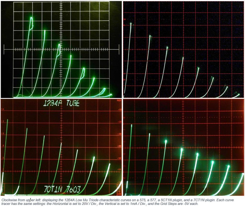
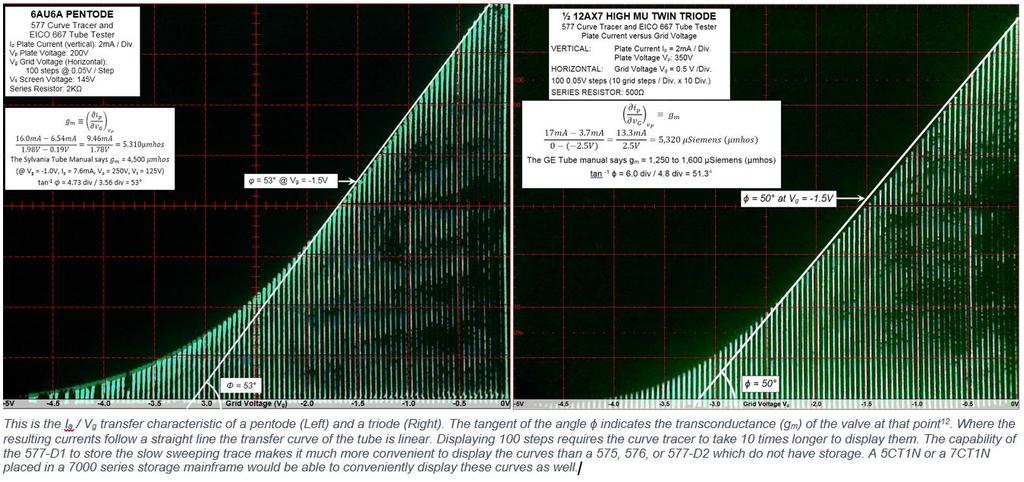
18 Pictures Picture #1: PN2222 Bipolar NPN transistor and a 6AU6A Sharp Cutoff Pentode simultaneously sharing the CRT of a 7844 (back cover of my paper). Picture #2: Pentode matching on a 577 Storage curve tracer Picture #3: Pentode characteristics and measuring g m, μ, and r p Picture #4: Triode characteristics and measuring g m, μ, and r p Picture #5: 12B4A Triode curves displayed on four different curve tracers to show the curves are the same Picture #6: I a vs. V g transfer characteristics of a pentode and a triode using 100 grid voltage steps

19

20

21

22
23
24
25 Demonstrations (time permitting) Triode Pentode Triode matching Pentode matching View inside the tube tester
26 Questions?
ELECTRICITY AND ELECTRONICS
 ELECTRICITY AND ELECTRONICS (Maximum Marks: 100) (Time allowed: Three hours) (Candidates are allowed additional 15 minutes for only reading the paper. They must NOT start writing during this time.) Answer
The Electro-Magnetic Spectrum
 The Electro-Magnetic Spectrum Part Three In This Issue: All about Tubes How a diode rectifier works How a triode amplifier works How the mixer in your receiver works Dear Friends: For quite some time I
GRID CONTROLLED POWER SUPPLY IS A VERSATILE UNIT Uses Pair of RCA-2050 s for Wide Voltage Range
 10/30/07 11:55 PM Thyratrons GRID CONTROLLED POWER SUPPLY IS A VERSATILE UNIT Uses Pair of RCA-2050 s for Wide Voltage Range By J. H. OWENS, W2FTW and G. D. HANCHETT, W1AK/2 RCA Ham Tips Volume 6, Number
Preface... xv Acknowledgments... xix. Chapter 1 An Overview of Vacuum Tube Audio Applications... 1
 Contents Preface... xv Acknowledgments... xix Chapter 1 An Overview of Vacuum Tube Audio Applications... 1 The Evolution of Analog Audio... 1 Technology Waves... 3 Tube vs. Solid State.................................................
PLATE CHARACTERISTICS
 PLATE CHARACTERISTICS In these calculations it is important to work with points equidistant on each side of Q to reduce to a minimum errors due to curvature. The plate characteristics of a pentode for
The metal outlet cover also makes a good template for drilling the holes in the plastic box. I used a 1.25-inch barrel-style wood bit (again, about
 BUILDING YOUR OWN EICO 615 TUBE TESTER ADAPTER If you own an EICO 667 Dynamic Conductance tube tester and you frequently encounter older 4, 5, 6, and 7-pin tubes, you probably wish you owned either the
Triplett 3444A Power Supply Modification Notes
 Triplett 3444A Power Supply Modification Notes The Triplett 3444A is a superb Tube Test/Analyzer. Mutual Conductance is measured by inserting a small known AC signal on the Grid, and measuring the AC Plate
CA4810A Curve Tracer User s Manual
 CA4810A Curve Tracer User s Manual Madell Technology Corporation http://www.madelltech.com Copyright 2005 CA4810A curve tracer is an instrument which can be used to view transistor and diode feature curves.
Copyright 1999 Wheatfield Audio LLC. All rights reserved. Printed in USA 11/99
 HA-2 Headphone Amplifier User s Manual Contents Safety... 3 Unpacking, Setup, and Connection... 4 Unpacking the amplifier... 4 Installing the tubes... 4 Connecting the amplifier... 4 Listening with the
HOM rev. new. Heath of the Month #80 - K-1 All-Wave Receiver. Heathkit of the Month #80: by Bob Eckweiler, AF6C AMATEUR RADIO - SWL
 Heathkit of the Month #80: by Bob Eckweiler, AF6C AMATEUR RADIO - SWL The Heathkit K-1 Three-Tube All-Wave Beginner s Receiver Some K-1 All-Wave Receiver History: The first piece of radio equipment using
Logic Gates & Training Boards
 Logic Gates & Training Boards ANALOG TO DIGITAL (A/D) CONVERTOR (ELP.112.140) Objective : To study Analog to Digital & Digital to Analog convertors using R-2R network & Successive Approximation Method.
Circuit Components Lesson 4 From: Emergency Management Ontario
 4.1 Amplifier Fundamentals The role of a amplifier is to produce an output which is an enlarged reproduction of the features of the signal fed into the input. The increase in signal by an amplifier is
Bipolar Junction Transistor (BJT)
") Bipolar Junction Transistor (BJT) - three terminal device - output port controlled by current flow into input port Structure - three layer sandwich of n-type and p-type material - npn and pnp transistors
Bipolar Junction Transistor (BJT) - three terminal device - output port controlled by current flow into input port Structure - three layer sandwich of n-type and p-type material - npn and pnp transistors
Lab: INTRODUCTION TO THE WAVEFORM GENERATOR AND THE OSCILLOSCOPE
 Name EET101/Lab#5; EET121/Lab#5; EGR104/Lab#3 Sec / Night Date Lab Partner(s) Name(s) Lab: INTRODUCTION TO THE WAVEFORM GENERATOR AND THE OSCILLOSCOPE Objectives: Each student will: 1. Know the function
Unusual Tubes. Tom Duncan, KG4CUY March 8, 2019
 Unusual Tubes Tom Duncan, KG4CUY March 8, 2019 Tubes On Hand GAS-FILLED HIGH-VACUUM Neon Lamp (NE-51) Cold-cathode Voltage Regulator (0B2) Hot-cathode Thyratron (884) Photomultiplier (931A) Magic Eye (1629)
Radio Merit Badge Boy Scouts of America
 Radio Merit Badge Boy Scouts of America Module 2 Electronics, Safety & Careers BSA National Radio Scouting Committee2012 Class Format Three modules any order Module 1 Intro To Radio Module 2 Electronic
TEACHING & EXAMINATION SCHEME For the Examination 2015 ELECTRONICS. B.Sc. Part - I
 TEACHING & EXAMINATION SCHEME For the Examination 2015 ELECTRONICS THEORY B.Sc. Part - I Elec. 101 Paper I Circuit Elements and Networks Pd/W Exam. Max. (45mts.) Hours Marks 150 2 3 50 Elec. 102 Paper
Marchand Electronics Inc
 . PO Box 8099, Rochester NY 8 Tel:(585) 3 0 Fax:(585) 3 9375 info@marchandelec.com www.marchandelec.com (c)00. MB Push-pull tube amplifier www.marchandelec.com 585 3 0 Parts List A section R R R3 R R5
Diodes. Analog Electronics Lesson 4. Objectives and Overview:
 Analog Electronics Lesson 4 Diodes Objectives and Overview: This lesson will introduce p- and n-type material, how they form a junction that rectifies current, and familiarize you with basic p-n junction
How a Vacuum Tube Guitar Amplifier Operates
 An Introduction How a Vacuum Tube Guitar Amplifier Operates Jacob Evans For decades, musicians of all types have trusted the tube guitar amplifier to deliver unparalleled tone and reliability for recording
Basic Electronics Learning by doing Prof. T.S. Natarajan Department of Physics Indian Institute of Technology, Madras
 Basic Electronics Learning by doing Prof. T.S. Natarajan Department of Physics Indian Institute of Technology, Madras Lecture 38 Unit junction Transistor (UJT) (Characteristics, UJT Relaxation oscillator,
PHYSICS 171 UNIVERSITY PHYSICS LAB II. Experiment 4. Alternating Current Measurement
 PHYSICS 171 UNIVERSITY PHYSICS LAB II Experiment 4 Alternating Current Measurement Equipment: Supplies: Oscilloscope, Function Generator. Filament Transformer. A sine wave A.C. signal has three basic properties:
070 ELECTRONICS WORKS EXAMINATION STRUCTURE
 070 ELECTRONICS WORKS EXAMINATION STRUCTURE The trade will be examined under the following components or subject grouping: Electronic Devices and Circuit, Radio Communication and Television. EXAMINATION
SECTION NEUTRALIZATION BELOW VHF NEUTRALIZATION
 SECTION 5 NEUTRALIZATION A completely neutralized amplifier must fulfill two conditions. The first is that the interelectrode capacitance between the input and output circuits be cancelled. The second
1. Summary. 15/08/2009 Philips Valve Amplifier Type LBH1015/01 Page 1 of 7. Valve PA Amplifier. Philips label Model Code LBH1015/01 Serial No 1080
 15/08/2009 Philips Valve Amplifier Type LBH1015/01 Page 1 of 7 1. Summary Valve PA Amplifier. Philips label Model Code LBH1015/01 Serial No 1080 Two input, mono 60W amplifier with tone control and 50V/70V/100V
DEPARTMENT OF ELECTRICAL ENGINEERING AND COMPUTER SCIENCE MASSACHUSETTS INSTITUTE OF TECHNOLOGY CAMBRIDGE, MASSACHUSETTS 02139
 DEPARTMENT OF ELECTRICAL ENGINEERING AND COMPUTER SCIENCE MASSACHUSETTS INSTITUTE OF TECHNOLOGY CAMBRIDGE, MASSACHUSETTS 02139 READING ASSIGNMENT 6.101 Introductory Analog Electronics Laboratory Laboratory
Power Supplies and Circuits. Bill Sheets K2MQJ Rudolf F. Graf KA2CWL
 Power Supplies and Circuits Bill Sheets K2MQJ Rudolf F. Graf KA2CWL The power supply is an often neglected important item for any electronics experimenter. No one seems to get very excited about mundane
120 VAC. 12 VAC center-tapped
 INST 200 (Introduction to Instrumentation), Review Exam MASTERY NAME: # Question type 1st attempt 2nd attempt 1 Circuit sketching 2-3 DC circuits 4-5 Mathematics 6 Circuit fault analysis 7-8 AC and opamp
VASE PA100, S.N. 116/100/ T. 6 microphone input channel PA amplifier. $ ebay Jan 2009
 19/03/2009 VASE P.A.100 AMPLIFIER Page 1 of 9 1. Summary VASE PA100, S.N. 116/100/ T. 6 microphone input channel PA amplifier. $121.40 ebay Jan 2009 Each microphone channel with BC109 input, followed by
Filament Thoriated tungsten. Filament voltage...14 volts Nominal filament current... 6 amperes Average thermionic emission...
 Classification Filamentary Air-cooled Triode. Application May be used as an audio-frequency amplifier or modulator; or as a radiofrequency oscillator or amplifier. Dimensions Large four-pin bayonet base
The 6LE8 One Tube Broadcaster
 The 6LE8 One Tube Broadcaster Introduction The purpose of this broadcaster is to transmit your favorite music to every AM radio in your home. The transmitting power is so low that it should not bother
Laboratory 4: Biasing of Bipolar Transistors Laboratory Exercises
 Laboratory 4: Biasing of Bipolar Transistors Laboratory Exercises INTRODUCTION Objectives In this lab, we will design and build three different bias circuits for BJT s (Bipolar Junction Transistors). In
ECE 2C Final Exam. June 8, 2010
 ECE 2C Final Exam June 8, 2010 Do not open exam until instructed to. Closed book: Crib sheet and 2 pages personal notes permitted There are 4 problems on this exam, and you have 3 hours. Use any and all
You Just Brought an Old Radio Home: Now What Do You Do?
 You Just Brought an Old Radio Home: Now What Do You Do? Raymond Cady goldenageradiorestoration.com Whether you are just beginning to collect antique radios or you have been at it for a number of years,
Western Electric 106 -A AMPLIFIER INSTRUCTION BULLETIN NO. 880, ISSUE NO. 2
 Western Electric 106 -A AMPLIFIER INSTRUCTION BULLETIN NO. 880, ISSUE NO. 2 Western Electric 106 -A AMPLIFIER Type Two -stage line or main Amplifier with bridging or matching input. A complete self -contained
C22 Vacuum Tube Preamplifier Complete User Manual Analog Metric
 C22 Vacuum Tube Preamplifier Complete User Manual Analog Metric sales@analogmetric.com Copyright 2009 All Rights Reserved [C22 VACUUM TUBE PREAMPLIFIER COMPLETE USER Page 2 INTRODUCTION The circuit design
(K-MOD102) TROUBLESHOOTING SUPPLEMENT
 TROUBLESHOOTING SUPPLEMENT") (K-MOD0) TROUBLESHOOTING SUPPLEMENT ON BASS TREBLE VOLUME OFF MOD 0 TUBE AMP KIT Use this supplement to help: Measure voltage test points to identify major discrepancies and locate problem areas. (Keep
(K-MOD0) TROUBLESHOOTING SUPPLEMENT ON BASS TREBLE VOLUME OFF MOD 0 TUBE AMP KIT Use this supplement to help: Measure voltage test points to identify major discrepancies and locate problem areas. (Keep
Calibration Testing of the Hickok Model 800/800A Tube Testers Version 1.0, September 2006 Daniel Schoo
 Calibration Testing of the Hickok Model 800/800A Tube Testers Version 1.0, September 2006 Daniel Schoo Use this procedure to test and calibrate the Hickok Model 800/800A mutual conductance (AKA transconductance)
Introduction PNP C NPN C
 Introduction JT Transistors: A JT (or any transistor) can be used either as a switch with positions of on or off, or an amplifier that controls its output at all levels in between the extreme on or off
EECE2412 Final Exam. with Solutions
 EECE2412 Final Exam with Solutions Prof. Charles A. DiMarzio Department of Electrical and Computer Engineering Northeastern University Fall Semester 2010 My file 11480/exams/final General Instructions:
An Easy-To-Build VFO
 An Easy-To-Build VFO By Lewis G. McCoy, W1ICP A VFO can he substituted in place of crystals and will permit the amateur to change his frequency to any point in the 80 or 40-meter bands. In other words,
Experiment # 4: BJT Characteristics and Applications
 ENGR 301 Electrical Measurements Experiment # 4: BJT Characteristics and Applications Objective: To characterize a bipolar junction transistor (BJT). To investigate basic BJT amplifiers and current sources.
Course Roadmap Rectification Bipolar Junction Transistor
 Course oadmap ectification Bipolar Junction Transistor Acnowledgements: Neamen, Donald: Microelectronics Circuit Analysis and Design, 3 rd Edition 6.101 Spring 2017 Lecture 3 1 6.101 Spring 2017 Lecture
Western Electric D V a c u u m T u b e
 284D Western Electric 2 8 4 D V a c u u m T u b e Classification Fiiamentary air-cooied triode The tube is designed primarily for use as an audio-frequency amplifier or modulator and may be used as a replacement
IPR LA-3 KIT last update 15 march 06
 IPR LA-3 KIT last update 15 march 06 PART-2: Audio Circuitry CIRCUIT BOARD LAYOUT: Power and Ground Distribution Now that your power supply is functional, it s time to think about how that power will be
Electric Druid Flangelicious Flanger Project
 Electric Druid Flangelicious Flanger Project (Using either 4KNOBFLANGE or MULTIFLANGE chips) Overview! 2 Build Instructions! 2 Populate the PCB! 2 1N4148 Diodes! 2 Resistors! 2 Cup of tea and soldering
Bonus Report. Brought to you by Jestine Yong.
 Bonus Report Brought to you by Jestine Yong http://www.electronicrepairguide.com You cannot give this bonus report away for free. You do not have the rights to redistribute this bonus report. Copyright@
Modifying The Heath HA-14 For 6 Meters Greg Chartrand - W7MY 4/22/07
 Introduction The Heathkit HA-14 was one of the few electron tube linear amplifiers intended for mobile use but few were purchased with the 12 volt mobile power supply. Most hams bought the HA-14 for base
DEPARTMENT OF ELECTRICAL ENGINEERING AND COMPUTER SCIENCE MASSACHUSETTS INSTITUTE OF TECHNOLOGY CAMBRIDGE, MASSACHUSETTS 02139
 DEPARTMENT OF ELECTRICAL ENGINEERING AND COMPUTER SCIENCE MASSACHUSETTS INSTITUTE OF TECHNOLOGY CAMBRIDGE, MASSACHUSETTS 039 READING ASSIGNMENT Spring Term 007 6.0 Introductory Analog Electronics Laboratory
TRACE ELLIOT SERVICE MANUAL NO. SM00025 ISSUE 1
 TRACE ELLIOT SERVICE MANUAL NO. SM00025 ISSUE 1 Date: January 6, 1997 Product Code : T3455/3456 Model No : Velocette 12R / Alnico Technical File No : TE00025 Issued by: Trace Elliot Limited. Blackwater
Vacuum Tube Modeling Package Vol. 1. Examples (Electronic edition)
") Vacuum Tube Modeling Package Vol. 1 Examples (Electronic edition) EXCEM Characteristics of our EL34 pentode model EXCEM 12, Chemin des Hauts de Clairefontaine 78580 Maule - France tel. 33 1 34 75 13 65
Vacuum Tube Modeling Package Vol. 1 Examples (Electronic edition) EXCEM Characteristics of our EL34 pentode model EXCEM 12, Chemin des Hauts de Clairefontaine 78580 Maule - France tel. 33 1 34 75 13 65
2 5 1 A Va c u u m T u b e
 251A 2 5 1 A Va c u u m T u b e P L A T E L E A D INSULATORS W SPRING CONNECTOR - P L A T E L E A D -FILAMENT LEADS CONNECTOR GRID LEAD Classification The 251A Vacuum Tube is a three element, air-cooled,
NEWSLETTER MAY 2010 VOLUME 10, No. 5
 NEWSLETTER MAY 010 VOLUME 10, No. 5 Mercury Amateur Radio Association - MARA - North America - North East CONTENTS TECH STUFF 3 AUDIO SIGNAL TRACER - PART 1 4 MARK TWAIN 4 NOTICES 4 DI-DAH-DI-DAH-DIT FINAL
Field - Effect Transistor
 Page 1 of 6 Field - Effect Transistor Aim :- To draw and study the out put and transfer characteristics of the given FET and to determine its parameters. Apparatus :- FET, two variable power supplies,
Vacuum Tube Amplifier
 Vacuum Tube Amplifier ECE 445 Design Document Qichen Jin and Bingqian Ye Group 1 TA: Zhen Qin Table of Contents 1 Introduction. 1 1.1 Objective.. 1 1.2 Background. 1 1.3 High-level requirements.. 2 2 Design..
UNITED MOTORS SERVICE D IV ISIO N OF GENERAL M O TO RS C O R P O R A T IO N. General Offices - Detroit AUTO RADIO BULLETIN
 UNITED MOTORS SERVICE D IV ISIO N OF GENERAL M O TO RS C O R P O R A T IO N General Offices - Detroit AUTO RADIO BULLETIN Bulletin 6D-855 Date 11-1-54 Page 1 FIRST ISSUE SUBJECT: SERVICE INSTRUCTIONS -
Basic Electronics Prof. T.S. Natarajan Department of Physics Indian Institute of Technology, Madras
 Basic Electronics Prof. T.S. Natarajan Department of Physics Indian Institute of Technology, Madras Lecture 39 Silicon Controlled Rectifier (SCR) (Construction, characteristics (Dc & Ac), Applications,
Lab 4: Junction Diodes
 Page 1 of 5 Laboratory Goals Analyzing, simulating and building a diode-based circuit. Taking measurements and applying transformations to obtain the diode I-V curve. Use the curve tracer to verify the
Understanding & Using The HA2500's Sub Drives
 Understanding & Using The HA2500's Sub Drives When horizontal drive to the horizontal output stage is missing, expensive horizontal output stage components cannot be determined good or bad. If horizontal
Device Interconnection
 Device Interconnection An important, if less than glamorous, aspect of audio signal handling is the connection of one device to another. Of course, a primary concern is the matching of signal levels and
Field Effect Transistors
 Field Effect Transistors Purpose In this experiment we introduce field effect transistors (FETs). We will measure the output characteristics of a FET, and then construct a common-source amplifier stage,
Maltase cross tube. D. Senthilkumar P a g e 1
 Thermionic Emission Maltase cross tube Definition: The emission of electrons when a metal is heated to a high temperature Explanation: In metals, there exist free electrons which are able to move around
Build an All-Tube Fuzz/Wah Pedal
 Build an All-Tube Fuzz/Wah Pedal by Eric Barbour and Peter Belov In spite of more than 30 years of development and marketing, to this day all commercial guitar "wah" pedals have been solid- state and have
Western E/ectrk A V a c u u m T u b e
 295A Western E/ectrk 2 9 5 A V a c u u m T u b e Classification Filamentary air- cooled triode May be used as an audio-frequency amplifier or as a radio-frequency amplifier, modulator o r o s c i l l a
Western Electric B a n d A Va c u u m Tu b e s. Classification Voitage amplifier, suppressor-grid pentodes with indirectiy heated
 V a c u u m T u b e s Western Electric 3 1 0 B a n d 3 4 8 A Va c u u m Tu b e s 4 -' 3108' m Classification Voitage amplifier, suppressor-grid pentodes with indirectiy heated cathodes. The 310B and 348A
Chapter 3. Bipolar Junction Transistors
 Chapter 3. Bipolar Junction Transistors Outline: Fundamental of Transistor Common-Base Configuration Common-Emitter Configuration Common-Collector Configuration Introduction The transistor is a three-layer
GT3W Series Dual Time Range Timers. CSA Certified File No.LR58183 LR96764 LR83814
 TW Series Courtesy of Steven Engineering, Inc. 0 Ryan Way, South San Francisco, CA, 00-70 Main Office: (50) 5-00 Outside Local Area: (00) 5-00 www.steveneng.com Specifications Time Range Rated Voltage
Bonus Report. Brought to you by Jestine Yong.
 Bonus Report Brought to you by Jestine Yong http://www.electronicrepairguide.com You cannot give this bonus report away for free. You do not have the rights to redistribute this bonus report. Copyright@
Keysight Technologies Measuring Power BJT Electrical Characteristics using the B1505A
 Keysight Technologies Measuring Power BJT Electrical Characteristics using the B1505A B1505A Power Device Analyzer/Curve Tracer Application Note Introduction The Keysight Technologies, Inc. B1505A Power
Archivist s Note: The plans are mislabeled and are actually for a tube-driven tremolo. See letter to the editor at the end of this document.
 Archivist s Note: The plans are mislabeled and are actually for a tube-driven tremolo. See letter to the editor at the end of this document. Build Your Own Vibrato Make like Elvis with an "electronic"
CHAPTER 6. Motor Driver
 CHAPTER 6 Motor Driver In this lab, we will construct the circuitry that your robot uses to drive its motors. However, before testing the motor circuit we will begin by making sure that you are able to
Questions on JFET: 1) Which of the following component is a unipolar device?
 Which of the following component is a unipolar device?") Questions on JFET: 1) Which of the following component is a unipolar device? a) BJT b) FET c) DJT d) EFT 2) Current Conduction in FET takes place due e) Majority charge carriers only f) Minority charge
Questions on JFET: 1) Which of the following component is a unipolar device? a) BJT b) FET c) DJT d) EFT 2) Current Conduction in FET takes place due e) Majority charge carriers only f) Minority charge
QUICKSILVER MX-190 OPERATING INSTRUCTIONS ,,-
 QUICKSILVER MX-190 OPERATING INSTRUCTIONS -------..,,- INPUT CONNECTIONS To maintain a short and concise signal path, the input connectors are mounted directly on the plug-in front-end circuit boards.
Triode Dick's Page. TentLabs filament supply. ...to apply with directly heated tubes
 Triode Dick's Page TentLabs filament supply...to apply with directly heated tubes A pleasant surprise A while ago I received a package with a pair of neat modules, with regards from Guido Tent, who runs
ECE 203 LAB 6: INVERTED PENDULUM
 Version 1.1 1 of 15 BEFORE YOU BEGIN EXPECTED KNOWLEDGE Basic Circuit Analysis EQUIPMENT AFG Oscilloscope Programmable Power Supply MATERIALS Three 741 Opamps TIP41 NPN power transistor TIP42 PNP power
Concepts to be Covered
 Introductory Medical Device Prototyping Analog Circuits Part 2 Semiconductors, http://saliterman.umn.edu/ Department of Biomedical Engineering, University of Minnesota Concepts to be Covered Semiconductors
Miscellaneous Devices
 Miscellaneous Devices Old Content - visit altium.com/documentation Modified by on 13-Sep-2017 The following miscellaneous schematic components can be found in the Miscellaneous Devices integrated library
DATASHEET HA Features. Applications. Ordering Information. Pinouts. 250MHz Video Buffer. FN2924 Rev 8.00 Page 1 of 12.
 25MHz Video Buffer NOT RECOMMENDED FOR NEW DESIGNS NO RECOMMENDED REPLACEMENT contact our Technical Support Center at -888-INTERSIL or www.intersil.com/tsc DATASHEET FN2924 Rev 8. The HA-533 is a unity
DIODE / TRANSISTOR TESTER KIT
 DIODE / TRANSISTOR TESTER KIT MODEL DT-100K Assembly and Instruction Manual Elenco Electronics, Inc. Copyright 1988 Elenco Electronics, Inc. Revised 2002 REV-K 753110 DT-100 PARTS LIST If you are a student,
22A3 Monaural Amplifier Owner s Manual
 22A3 Monaural Amplifier Owner s Manual www.bandwidthaudio.com sales@bandwidthaudio.com WARNING Never power on the amplifier without connecting a proper load Failure to do so will result in permanent damage
EE70 - Intro. Electronics
 EE70 - Intro. Electronics Course website: ~/classes/ee70/fall05 Today s class agenda (November 28, 2005) review Serial/parallel resonant circuits Diode Field Effect Transistor (FET) f 0 = Qs = Qs = 1 2π
Three Terminal Devices
 Three Terminal Devices - field effect transistor (FET) - bipolar junction transistor (BJT) - foundation on which modern electronics is built - active devices - devices described completely by considering
E2500 Antenna Installation Instructions:
 Thank you for purchasing the Antenna Mod Kit for your Linksys router. First we will show you how to install the antennas for your router. We will also provide you with a tool that will help test the performance
o Semiconductor Diode Symbol: The cathode contains the N-type material and the anode contains the P-type material.
 Cornerstone Electronics Technology and Robotics I Week 16 Diodes and Transistor Switches Administration: o Prayer o Turn in quiz Review: o Design and wire a voltage divider that divides your +9 V voltage
Swr Analyzer Foxdelta
 Swr Analyzer Foxdelta 1 / 6 2 / 6 3 / 6 Swr Analyzer Foxdelta SWR ANALYZER v6.00 by Tony, i2tzk Page. Connect the SWR Analyzer Unit to the PC or Laptop using a standard USB cable (printer cable), after
Experiment P49: Transistor Lab 2 Current Gain: The NPN Emitter-Follower Amplifier (Power Amplifier, Voltage Sensor)
") PASCO scientific Vol. 2 Physics Lab Manual: P49-1 Experiment P49: Transistor Lab 2 Current Gain: The NPN Emitter-Follower Amplifier (Power Amplifier, Voltage Sensor) Concept Time SW Interface Macintosh
PASCO scientific Vol. 2 Physics Lab Manual: P49-1 Experiment P49: Transistor Lab 2 Current Gain: The NPN Emitter-Follower Amplifier (Power Amplifier, Voltage Sensor) Concept Time SW Interface Macintosh
A 75-Watt Transmitter for 3 Bands Simplified Shielding and Filtering for TVI BY DONALD H. MIX, W1TS ARRL Handbook 1953 and QST, October 1951
 A 75-Watt Transmitter for 3 Bands Simplified Shielding and Filtering for TVI BY DONALD H. MIX, W1TS ARRL Handbook 1953 and QST, October 1951 The transmitter shown in the photographs is a 3-stage 75-watt
Professional Equalizer-Preamp Suitable for Home Use
 A combined Professional Equalizer-Preamp Suitable for Home Use KENNETH W. BETSH* Designed originally for broadcast-station use, this preamplifier can be adapted to any installation where it would be desirable
Laboratory 3 (drawn from lab text by Alciatore)
") Laboratory 3 (drawn from lab text by Alciatore) The Oscilloscope Required Components: 1 10 resistor 2 100 resistors 2 lk resistors 1 2k resistor 2 4.7M resistors 1 0.F capacitor 1 0.1 F capacitor 1 1.0uF
Laboratory 3 (drawn from lab text by Alciatore) The Oscilloscope Required Components: 1 10 resistor 2 100 resistors 2 lk resistors 1 2k resistor 2 4.7M resistors 1 0.F capacitor 1 0.1 F capacitor 1 1.0uF
Galaxy DX949, 959, 2547 ERF-2030 Mod Package This Mod Package is provided by
 This Mod Package is provided by CBTricks.com Someone who wanted to help you repair your equipment put together this information. Galaxy DX949, 959, 2547 ERF-2030 Mod Package This mod will also work on
ECE 121 Electronics (1)
") ECE 121 Electronics (1) Lec. 1: Introduction to BJT Instructor Dr. Maher Abdelrasoul http://www.bu.edu.eg/staff/mahersalem3 1 Outline Course Information Course Objectives BJT Introduction Transistor Construction
ECE 121 Electronics (1) Lec. 1: Introduction to BJT Instructor Dr. Maher Abdelrasoul http://www.bu.edu.eg/staff/mahersalem3 1 Outline Course Information Course Objectives BJT Introduction Transistor Construction
Miscellaneous Devices
 Miscellaneous Devices Old Content - visit altium.com/documentation Mod ifi ed by Phi l Lou ghh ead on 4- Mar -20 14 The following miscellaneous schematic components can be found in the Miscellaneous Devices
HOM rev. new Heathkit of the Month #79: by Bob Eckweiler, AF6C. Heath of the Month #79 - VF-1 VFO AMATEUR RADIO - SWL
 Heathkit of the Month #79: by Bob Eckweiler, AF6C AMATEUR RADIO - SWL Heathkit VF-1 External VFO (Variable Frequency Oscillator). Introduction: In 1951 the FCC totally revamped the license classes for
Frigate Headphone Amplifier With Two 6922 & Two 6H30Pi Tubes
 Frigate Headphone Amplifier With Two 6922 & Two 6H30Pi Tubes Augustica w w w. a u g u s t i c a. c o m DANGER This amplifier kit has a high-voltage power supply, which provides high voltage and therefore
PA-1 Stereo power amplifier
 PA-1 Stereo power amplifier The new PA-1 Stereo power amplifier is upgraded on the PA-1 mono block amplifier, the peak output power can reach 200W per It adopts the independent dual mono circuit design,
SUBELEMENT T6 Electrical components: semiconductors; circuit diagrams; component functions 4 Exam Questions - 4 Groups
 SUBELEMENT T6 Electrical components: semiconductors; circuit diagrams; component functions 4 Exam Questions - 4 Groups 1 T6A Electrical components: fixed and variable resistors; capacitors and inductors;
Approximate Circuit Model for a Magnetic Pickup Piezoelectric Pickups Piezoelectric Pickup Analysis Guitar Volume and Tone Control
 Contents 1 Power Supplies... 1 Introduction... 1 A Simple Power Supply Circuit..... 1 The Transformer.............. 2 The Rectifier........................................................ 3 The Frequency
Electronics Review 2 Cornerstone Electronics Technology and Robotics II
 Electronics Review 2 Cornerstone Electronics Technology and Robotics II Administration: o Prayer o Bible Verse Hacksaws: o Vertical and horizontal positions o Hacksaw blade must be positioned with the
Concepts to be Reviewed
 Introductory Medical Device Prototyping Analog Circuits Part 3 Operational Amplifiers, http://saliterman.umn.edu/ Department of Biomedical Engineering, University of Minnesota Concepts to be Reviewed Operational
HANDS-ON LAB INSTRUCTION SHEET MODULE 3 CAPACITORS, TIME CONSTANTS AND TRANSISTOR GAIN
 HANDS-ON LAB INSTRUCTION SHEET MODULE 3 CAPACITORS, TIME CONSTANTS AND TRANSISTOR GAIN NOTES: 1) To conserve the life of the Multimeter s 9 volt battery, be sure to turn the meter off if not in use for