Electromechanical Relays Selection Guide
|
|
|
- Roy Sims
- 6 years ago
- Views:
Transcription

1 Electromechanical Relays Selection Guide Latching JAN Non-Latching RF DC - GHz Established Reliability Loopback PST Environmental Attenuated

 Instrumentation & Test Industrial Power & Motion Control Medical Applications IC")
 and ISO 00:00 Teledyne Relays has become a primary supplier of switching solutions with the highest quality and")
2 Switching Solutions Teledyne Relays has been the world s innovative leader in the manufacture of ultraminiature, hermetically sealed, electromechanical and solid-state switching products for more than 0 years. The company s comprehensive product line meets a wide range of requirements for defense and aerospace, industrial, commercial, medical and RF & wireless applications. Business Focus MIL QPL & COTS Solid-State Relays MIL QPL & COTS Electromechanical Relays HiRel (Space) Electromechanical Relays RF & Microwave Relays & Coaxial Switches Industrial Solid-State Relays Switching Matrices Markets Commercial & Military Aviation Defense & Aerospace Telecom/Communications (Wireless) Instrumentation & Test Industrial Power & Motion Control Medical Applications IC Semiconductor Test Oil & Gas Product Assurance Under an aggressive Total Quality Management (TQM) program, Teledyne Relays has embraced a continuous improvement culture. With recognized certifi cations such as Boeing D-, MIL-STD-0, AS/EN/ JISQ00:00 (Rev C) and ISO 00:00 Teledyne Relays has become a primary supplier of switching solutions with the highest quality and reliability to industry leaders around the world. Technical Service & Customer Support Teledyne Relays provides easy access to technical service and customer support. Our websites make it easy to fi nd technical information, buy products and even get responses within hours. Switching solutions are only a mouse click away at or at teledyne-europe.com. Information about coax switches is available at Teledyne Relays offer superior signal integrity up to 0 Gbps. See the RF relays section in our website.
3 Table of Contents RF RELAYS Series Description Page RF / GRF DC- GHz, Signal Integrity up to 0 Gbps, Mag-Latching SPDT - LB/GLB/SGLB LoopBack Relay with Built-in AC Bypass Capacitors - RF/GRF/SGRF/SRF00 High Repeatability, Broadband TO- Relays, Non-Latching DPDT - RF/GRF/SGRF/SRF0 SI00 / SI0 Signal Integrity up to 0 Gbps, Non-Latching DPDT 0- RF/GRF/SGRF00 RF/GRF/SGRF0 High Repeatability, Broadband Centigrid Relays, Non-Latching DPDT RF00/RF0 High Repeatability, Broadband Centigrid Relays, Non-Latching DPDT RF/GRF RF/GRF High Repeatability, Broadband TO- Relays, Non-Latching SPDT RF/GRF Broadband TO- RF Relays, Magnetic-Latching SPDT RF/ High Power DPDT Half-Size Crystal Can Relay GRF Surface-Mount TO- RF Relays, Magnetic-Latching DPDT RF0/GRF0 Broadband RF Relays, Magnetic-Latching DPDT GRF Surface-Mount Centigrid RF Relays, Non-Latching DPDT RF/GRF/SGRF Surface-Mount PST TO- Relay RF0/RF High Repeatability TO- Relays, Normally Closed, Bypass RF0/RF High Repeatability TO- Relays, Normally Open, Bypass A0/GA0 Broadband Attenuator RF Relay A/GA Broadband Attenuator RF Relay COMMERCIAL RELAYS C Centigrid Relays (CMOS Compatible), Magnetic-Latching DPDT Centigrid Relays, Non-Latching DPDT TO- Relays, Non-Latching DPDT 0 TO- Relays, Magnetic-Latching DPDT 0 TO- Relays, Non-Latching Sensitive DPDT COMMERCIAL SURFACE-MOUNT RELAYS S Surface-Mount Centigrid Relays, Non-Latching DPDT S Surface-Mount Centigrid Relays, Non-Latching Sensitive DPDT S Surface-Mount Centigrid Relays, Non-Latching DPDT S Surface-Mount TO- Relays, Magnetic-Latching DPDT See specific series for additional features and options Continued on next page 0 TELEDYNE RELAYS SPECIFICATIONS SUBJECT TO CHANGE WITHOUT NOTICE Page
4 Table of Contents ESTABLISHED RELIABILITY RELAYS Series Description Page ER Centigrid Relays, Non-Latching DPDT ERC Centigrid Relays (CMOS Compatible), Non-Latching DPDT ER Centigrid Relays, Non-Latching Sensitive DPDT ERC Centigrid Relays (CMOS Compatible), Non-Latching Sensitive DPDT ER TO- Relays, Non-Latching SPDT ER TO- Relays, Non-Latching Sensitive SPDT ER TO- Relays, Non-Latching DPDT ER TO- Relays, Non-Latching Sensitive DPDT / Half-Size Crystal Can, Magnetic-Latching DPDT ER TO- Relays, Magnetic-Latching SPDT ER0 TO- Relays, Magnetic-Latching DPDT ER TO- Relays, Magnetic-Latching DPDT MILITARY QUALIFIED (JAN) RELAYS J Centigrid Relays, Non-Latching DPDT 0 JC Centigrid Relays (CMOS Compatible), Non-Latching DPDT 0 J Centigrid Relays, Non-Latching Sensitive DPDT JC Centigrid Relays (CMOS Compatible), Non-Latching Sensitive DPDT J TO- Relays, Non-Latching SPDT J TO- Relays, Non-Latching Sensitive SPDT J TO- Relays, Non-Latching DPDT J TO- Relays, Non-Latching Sensitive DPDT J Half-Size Crystal Can, Magnetic-Latching DPDT J TO- Relays, Magnetic-Latching SPDT J0 TO- Relays, Magnetic-Latching DPDT J TO- Relays, Magnetic-Latching DPDT See specific series for additional features and options Continued on next page Page (00) (0) 0 TELEDYNE RELAYS

 - GRF Option TO- Relays with straight butt pins for surfacemount applications * RF Relays Only SGRF Option TO- Relays with Gull-Wing (J-Lead)")
5 Table of Contents HIGH-PERFORMANCE RELAYS Description Page H/H High-Temperature (00 C) TO- Relays, Non-Latching DPDT H High-Temperature (00 C) TO- Relays, Magnetic-Latching DPDT K High-Shock TO- Relays, Non-Latching DPDT K High-Shock TO- Relays, Magnetic-Latching DPDT V/V High-Vibration TO- Relays, Non-Latching DPDT APPENDIX Signal Integrity Eye Diagrams -0 RoHS and Reach Certifi cate of Compliance Part Numbering System - Dimensions - Handling Guidelines Spacer Pad Options Spreader Pad Options Ground Pin Options Established Reliability Program -0 Teledyne Relays HI-REL Program OTHER TELEDYNE PRODUCTS (EMR, COAX, ISSR, MSSR, MATRIX, SPACE) - GRF Option TO- Relays with straight butt pins for surfacemount applications * RF Relays Only SGRF Option TO- Relays with Gull-Wing (J-Lead) pins for surface-mount applications * RF Relays Only GRF Option Centigrid Relays with straight butt pins for surface-mount applications * RF Relays Only SGRF Option TO- Relays with Gull-Wing (J-Lead) pins for surface-mount applications * RF Relays Only SRF Option Relays with Gull-Wing (J-Lead) pins for surface-mount applications * RF Relays Only /S Option Relays with 0. trimmed leads See Appendix: Part Numbering System Spacer Pad Option Relays with polyester fi lm pad to space between PCB and Relay Header See Appendix: Spacer Pad Options Spreader Pad Option Relays with Diallyl Phthalate pad to spread pins See Appendix: Spreader Pad Options /Q, /R Option Relays with solder dipped leads. Pb/Sn (0/0) or RoHS solder available See Appendix: Part Numbering System See specific series for additional features and options 0 TELEDYNE RELAYS SPECIFICATIONS SUBJECT TO CHANGE WITHOUT NOTICE Page

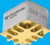
 Excellent Signal integrity up to 0Gbps Hermetically Sealed High Resistance to ESD Metal Enclosure for EMI shielding High Repeatability Million Cycle Life RF SPDT")
6 RF RELAYS Series GRF Electromechanical Relays The ultraminiature GRF relay is designed to provide a practical surface-mount switching solution with RF performance and repeatability to GHz. The GRF improves on Teledyne Relays heritage of miniature RF relays by incorporating a precision trasmission line structure in the internal construction of the contact system. GRF relays feature a unique ground shield to facilitate surface mounting and to extend the frequency range when compared to through-hole solutions. Broader bandwidth (DC - GHz) Excellent Signal integrity up to 0Gbps Hermetically Sealed High Resistance to ESD Metal Enclosure for EMI shielding High Repeatability Million Cycle Life RF SPDT Magnetic-Latching Frequency Range RF = DC - GHz GRF = DC - GHz Bit Rate RF = 0 Gbps GRF = 0 Gbps Mounting RF = Thru-hole GRF = Surface-Mount (Stub) Available Coil Voltages V: Coil Resistance (Ω) = V: Coil Resistance (Ω) = 00 Temperature Storage: C to + C Operating: C to + C RF GRF Frequency (GHz) Typical RF Performance VSWR (max) Isolation (db) Insertion Loss (db) (max) DC -. : : : 0. DC -. : : : : 0 0. GRF RF Characteristics 0 Insertion Loss. VSWR -0.. Insertion Loss (db) VSWR Frequency (GHz) 0 0 Frequency (GHz) 0 Isolation Isolation (db) Frequency (GHz) CONTACTS SHOWN IN POSITION RESULTING WHEN COIL A LAST ENERGIZED Schematics as viewed from terminals Page (00) (0) 0 TELEDYNE RELAYS
7 RF RF RF RELAYS Gbps Gbps Bit Rate Eye Height Eye Width Jitter P-P Gbps 0 mv. ps. ps Gbps Gbps Bit Rate Eye Height Eye Width Jitter P-P Gbps. mv. ps. ps 0Gbps 0Gbps Bit Rate Eye Height Eye Width Jitter P-P 0 Gbps mv. ps. ps 0 TELEDYNE RELAYS SPECIFICATIONS SUBJECT TO CHANGE WITHOUT NOTICE Page
 applications. The LoopBack combines the technology of two Teledyne SGRF0 Series relays and eliminates the need for external PCB traces in loop back applications.")

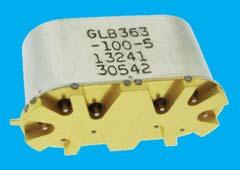
8 LOOPBACK RELAYS RF RF Series LB/GLB/SGLB Electromechanical Relays The LoopBack Series relays combines to DPDT electromechanical relays in one package that includes an internal bypass path for Automated Test Equipment (ATE) applications. The LoopBack combines the technology of two Teledyne SGRF0 Series relays and eliminates the need for external PCB traces in loop back applications. This innovation results in superior signal integrity and RF performance while taking minimal board space. The internal structure of the LoopBack relays reduces the number of discontinuities and shortens the signal path during loop back testing, providing lower insertion loss and higher signal integrity performance than two SGRF0 Series relays. This LoopBack Relay is available with surface mount ground shield and J-lead confi guration to provide improved high data rate and high frequency performance and ease of surface mount attachment. Two DPDT Relays Capacitor Value 000 = No capacitor 00 = 0nF 00 = 00nF 0 = 0nF Mounting LB = Thru-hole GLB = Surface-Mount Ground Shield (Stub) SGLB = Surface-Mount Ground Shield(J-Lead) Temperature Storage: C to + C Operating: C to + C LB Part Number Excellent Signal integrity up to Gbps Hermetically Sealed High Resistance to ESD Metal Enclosure for EMI shielding High Repeatability Broader bandwidth Through-hole or surface-mount confi gurations Million Cycle Life LB GLB SGLB Voltage,,, Coil Resistance (Ω), 00, 00, 00 Frequency (GHz) DC- DC- DC- AC Bypass Path (Thru-CAP) Single-Ended Bit Gbps Eye Height (mv) Eye Width (ps) Jitter p-p (ps) Through Path Single-Ended Bit Gbps Eye Height (mv) Eye Width (ps) Jitter p-p (ps) AC Bypass Path (Thru-CAP) Single-Ended Bit Gbps Eye Height (mv) Eye Width (ps) Jitter p-p (ps) Through Path Single-Ended Bit Gbps Eye Height (mv) Eye Width (ps) Jitter p-p (ps) GLB SGLB DC TEST JITTER INSPECTION BIST LOOPBACK DPDT ATE AT SPEED CHARACTERIZATION CAP CAP DUT TX Slow speed signals routed to ATE RX (Contacts shown in De-Energized position) Figure : Single LoopBack Relay DPDT Figure : DPDT Relays with external capacitors Schematics as viewed from terminals Page (00) (0) 0 TELEDYNE RELAYS


9 LOOPBACK RELAYS Dual SGRF0 Loopback Single LB Loopback.Gbps PRBS0.Gbps PRBS0 RF Dual SGRF0 Loopback Single LB Loopback. Gbps PRBS0. Gbps PRBS0 X DPDT relay LoopBack relay oss (db) Insertion Lo P - SN P - SN Dual RF0 - P P - SN P - SN Dual RF0 - P Frequency (MHz) A single LB has better Insertion Loss performance than SGRF0 relays in a LoopBack application 0 TELEDYNE RELAYS SPECIFICATIONS SUBJECT TO CHANGE WITHOUT NOTICE Page
10 RF RELAYS Series RF00/RF0 Electromechanical Relays The RF00 and RF0 TO- relays are designed to provide improved RF signal repeatability over the frequency range. The RF00 Series is offered with a standard or sensitive coil. The GRF00 and GRF0 TO- relays feature a unique ground shield that isolates and shields each lead to ensure excellent contact-to-contact and pole-to-pole isolation. This ground shield provides a ground interface that results in improved high-frequency performance as well as parametric repeatability. The SGRF00 and SGRF0 TO- relays extend performance advantages over similar RF devices that simply offer formed leads for surface mounting. Excellent Signal integrity up to Gbps+ Hermetically Sealed Metal Enclosure for EMI shielding High Repeatability Broader bandwidth Through-hole or surface-mount confi gurations 0 Million Cycle Life RF Typical RF Performance DPDT Non-Latching Coil Type 00 = Standard Coil 0 = Sensitive Coil Diode Option D = Internal diode for coil transient suppression DD = Internal diode for coil transient suppression and polarity reversal protection Mounting RF = Thru-hole GRF = Surface-Mount (Stub) SGRF = Surface-Mount (J-Lead) SRF = Surface Mount (J-Lead) Temperature Storage: C to + C Operating: C to + C RF00 RF00D RF0 RF0D GRF00 GRF00D GRF0 GRF0D SGRF00 SGRF00D SGRF0 SGRF0D SRF00 SRF00D Frequency (GHz) VSWR (max) Pole to Pole (min) Isolation (db) Across Contacts (min) Insertion Loss (db) (max) DC-. : : : 0 0. DC-. : : : :.0 DC-. : : : : DC-. : : 0. SRF0 -.0 :.0 SRF0D -. : Voltage Nominal Coil* Resistance (Ω) 00D 0D RF00 0 RF00D 0 RF0 00 RF0D 0 For RF00DD & RF0DD values, please see Datasheet. *RF, GRF, SGRF and SRF have equivalent Voltage Options and Coil Resistance. 00DD 0DD Schematics as viewed from terminals Page (00) (0) 0 TELEDYNE RELAYS


11 RF RF RF RELAYS Gbps Eye Height Eye Width Jitter P-P mv. ps.0 ps Gbps Eye Height Eye Width Jitter P-P mv. ps 0. ps 0 Gbps Eye Height Eye Width Jitter P-P mv. ps. ps 0 TELEDYNE RELAYS SPECIFICATIONS SUBJECT TO CHANGE WITHOUT NOTICE Page
12 RF RELAYS Series SI00/SI0 Electromechanical Relays The miniature SI00/SI0 Series is designed for high-speed digital applications. They are capable of transmitting high-sped signals with data rates up to 0 Gbps. The SI00 series has a lower profi le but higher coil operating power; whereas the SI0 Series has lower coil operating power but has a higher profi le. Excellent Signal integrity up to 0Gbps High Repeatability Hermetically Sealed High Resistance to ESD Metal Enclosure for EMI shielding Ground pin option to improve case grounding Million Cycle Life RF DPDT Non-Latching Coil Type SI00= Standard Coil SI0 = Sensitive Coil Temperature Storage: C to + C Operating: C to + C SI00 SI0 Frequency (GHz) VSWR (max) Typical RF Performance Pole to Pole (min) Isolation (db) Across Contacts (min) Insertion Loss (db) (max) DC-. : : : 0 0. SI00 SI0 Voltage Nominal Coil Resistance (Ω) SI00 SI0 Schematics as viewed from terminals SI00 Time Response % ps reference Volt 0..ps propagation delay time ps pulse rise time 0% Time (ps) Data is the average from readings taken on all closed contacts. Page 0 (00) (0) 0 TELEDYNE RELAYS


13 RF RELAYS Gbps Eye Height Eye Width Jitter P-P mv. ps. ps RF RF Gbps Eye Height Eye Width Jitter P-P mv. ps. ps 0 Gbps Eye Height Eye Width Jitter P-P mv ps 0. ps 0 TELEDYNE RELAYS SPECIFICATIONS SUBJECT TO CHANGE WITHOUT NOTICE Page

14 RF RELAYS RF Series RF00/RF0 Electromechanical Relays The RF00 and RF0 Centigrid relays are designed to provide improved RF signal repeatability over the frequency range. The GRF00 and GRF0 Centigrid relays feature a unique ground shield that isolates and shields each lead to ensure excellent contact-to-contact and pole-to-pole isolation. This ground shield provides a ground interface that results in improved high-frequency performance as well as parametric repeatability. The SGRF00 and SGRF0 Centigrid relays extend performance advantages over similar RF devices that simply offer formed leads for surface mounting DPDT Non-Latching Coil Type 00 = Standard Coil 0 = Sensitive Coil RF00 Coil Voltage V: Coil Resistance (Ω) = 0 V: Coil Resistance (Ω) = 0 RF0 Coil Voltage V: Coil Resistance (Ω) = 00 V: Coil Resistance (Ω) = 00 Mounting RF = Thru-hole GRF = Surface-Mount (Stub) SGRF = Surface-Mount (J-Lead) Temperature Storage: C to + C Operating: C to + C RF00 RF0 GRF00 GRF0 SGRF00 SGRF0 Frequency (GHz) VSWR (max) Excellent Signal integrity up to Gbps Hermetically Sealed High Resistance to ESD Metal Enclosure for EMI shielding High Repeatability Broader bandwidth Through-hole or surface-mount confi gurations 0 Million Cycle Life Typical RF Performance Pole to Pole (min) Isolation (db) Across Contacts (min) Insertion Loss (db) (max) DC-. : : : DC-. : : : : 0. DC-. : : : :.0 Series RF00/RF0 Electromechanical Relays The ultraminiature RF00 and RF0 relays are designed to provide improved RF signal switching repeatability over the frequency range. These relays are engineered for use in RF attenuator, RF switch matrices, ATE and other applications that require dependable high frequency signal fi delity and performance. The Series RF00/RF0 relays have internal discrete silicon diodes for coil suppression and polarity reversal protection. This hybrid package reduces required PC board fl oor space by reducing the number of external components needed to drive the relay Hermetically Sealed High Resistance to ESD Metal Enclosure for EMI shielding High Repeatability Broader bandwidth Through-hole or surface-mount confi gurations Million Cycle Life 00 0 DPDT Non-Latching Coil Type 00 = Standard Coil 0 = Sensitive Coil Mounting RF = Thru-hole GRF = Surface-Mount (Stub) SGRF = Surface-Mount (J-Lead) Temperature Storage: C to + C Operating: C to + C RF00 RF0 Frequency (GHz) VSWR (max) Typical RF Performance Pole to Pole (min) Isolation (db) Across Contacts (min) Insertion Loss (db) (max) DC-. : : : : Voltage Nominal Coil Resistance (Ω) RF RF Page (00) (0) 0 TELEDYNE RELAYS
15 RF RELAYS Series RF/RF Electromechanical Relays The RF/RF relays are designed to provide improved RF signal repeatability over the frequency range. These relays are highly suitable for use in attenuator and other RF circuits. The GRF offers monotonic insertion loss to GHz. This improvement in RF insertion loss over the frequency range makes these relays highly suitable for use in attenuator and other RF circuits. The GRF features a unique ground shield that isolates and shields each lead to ensure excellent contact-to-contact isolation. This ground shield provides a ground interface that results in improved high-frequency performance as well as parametric repeatability. Excellent Signal integrity up to 0Gbps Hermetically Sealed High Resistance to ESD Metal Enclosure for EMI shielding High Repeatability Broader bandwidth Through-hole or surface-mount confi gurations 0 Million Cycle Life RF SPDT Non-Latching Coil Type = Standard Coil = Sensitive Coil RF Coil Voltage V: Coil Resistance (Ω) = 0 V: Coil Resistance (Ω) = 0 V: Coil Resistance (Ω) = 000 RF Coil Voltage V: Coil Resistance (Ω) = V: Coil Resistance (Ω) = 0 V: Coil Resistance (Ω) = 000 Mounting RF = Thru-hole GRF = Surface-Mount (Stub) Temperature Storage: C to + C Operating: C to + C RF GRF RF Frequency (GHz) Typical RF Performance VSWR (max) Isolation Across Contacts (db) (min) Insertion Loss (db) (max) DC-. : : : : 0. DC-. : : : : 0.0 DC-. : : : : 0. Schematics as viewed from terminals Series RF Electromechanical Relays The RF series relay is an ultraminiature, hermetically sealed, magnetic-latching relay featuring extremely low intercontact capacitance for exceptional RF performance well into the C band. Its low profi le and small size make it ideal for applications where extreme packaging density and/or close PC board spacing are required. Due to its minimal mass, many relays may be used to confi gure replacements for bulkier switching solutions at substantial savings in weight. The RF design has been optimized by increasing the distance between the set/reset contacts. This design improvement makes these unique relays the perfect choice for use in RF attenuators, RF switching matrices and other RF applications requiring high isolation, low insertion loss and low VSWR. The GRF features a unique ground shield that isolates and shields each lead to ensure excellent contactto-contact isolation. This ground shield provides a ground interface that results in improved high-frequency performance as well as parametric repeatability. Excellent Signal integrity up to 0Gbps Hermetically Sealed High Resistance to ESD Metal Enclosure for EMI shielding High Repeatability Broader bandwidth Through-hole or surface-mount confi gurations 0 Million Cycle Life SPDT Magnetic-Latching Coil Type = Standard Coil RF Coil Voltage V: Coil Resistance (Ω) = V: Coil Resistance (Ω) = 00 V: Coil Resistance (Ω) = 000 Mounting RF = Thru-hole GRF = Surface-Mount (Stub) Temperature Storage: C to + C Operating: C to + C RF GRF Frequency (GHz) Typical RF Performance 0 TELEDYNE RELAYS SPECIFICATIONS SUBJECT TO CHANGE WITHOUT NOTICE Page VSWR (max) Isolation Across Contacts (db) (min) Insertion Loss (db) (max) DC-. : : : 0.0 DC-. : : :. COIL A _ Schematics as viewed from terminals + SCHEMATIC (Coil A Last Energized) + COIL B _
 and other RF circuits.")
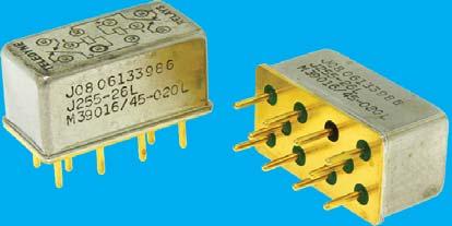
16 RF RELAYS RF Series RF/RF Electromechanical Relays The Series RF/ The Series RF is an industry-standard, half-size, latching crystal can relay. These relays are highly suitable for high RF power applications (RF Power Handling) and other RF circuits. Teledyne Relays Series RF offers: all welded construction, wire leads, gold-plated or solder-coated, matched seal for superior hermeticity, gold-plated contact assembly, modernized assembly process and advanced cleaning techniques. Excellent Signal integrity up to 0Gbps Hermetically Sealed High Resistance to ESD Metal Enclosure for EMI shielding High Repeatability Broader bandwidth Through-hole or surface-mount confi gurations Million Cycle Life DPDT Magnetic-Latching Mounting RF = Thru-hole RF Coil Voltage V: Coil Resistance (Ω) = V: Coil Resistance (Ω) = V: Coil Resistance (Ω) = V: Coil Resistance (Ω) = 000 Temperature Storage: C to + C Operating: C to + C RF RF Frequency (GHz) VSWR (max) Typical RF Performance Pole to Pole (min) Isolation (db) Across Contacts (min) Insertion Loss (db) (max) DC-.0: : : RF B A A X Y X RF B A A X Y X Y Y B B A B B A SCHEMATIC (Coil X Last Energized) (Bottom View) Series GRF Electromechanical Relays The Series GRF relay is a hermetically sealed, RF relay designed from inception for surface mount applications. This magnetic-latching relay features extremely low internal circuit losses for exceptional time and frequency domain response characteristics through and beyond the UHF spectrum and into the S band. The GRF features a unique ground shield that isolates and shields each lead to ensure excellent contact-to-contact and pole-to-pole isolation. This ground shield provides an RF ground interface that results in improved high-frequency performance as well as parametric repeatability. The GRF extends performance advantages over similar RF devices that simply offer formed leads for surface mounting. Excellent Signal integrity up to 0Gbps Hermetically Sealed High Resistance to ESD Metal Enclosure for EMI shielding High Repeatability Broader bandwidth Through-hole or surface-mount confi gurations 0 Million Cycle Life DPDT Magnetic-Latching Coil Type = Standard Coil RF Coil Voltage V: Coil Resistance (Ω) = V: Coil Resistance (Ω) = 00 Mounting GRF = Surface-Mount (Stub) Temperature Storage: C to + C Operating: C to + C GRF Frequency (GHz) VSWR (max) Typical RF Performance Pole to Pole (min) Isolation (db) Across Contacts (min) GRF Insertion Loss (db) (max) DC-. : : : 0. COIL B Schematics as viewed from terminals COIL A SCHEMATIC (Coil A Last Energized) Page (00) (0) 0 TELEDYNE RELAYS
17 RF RELAYS Series RF0/GRF0 Electromechanical Relays The Series RF0 relay is a hermetically sealed, magnetic-latching relay featuring extremely low intercontact capacitance for exceptional RF performance over the full UHF spectrum. Its low profi le height and.00 (. mm) grid spaced terminals make it ideal for applications where extreme packaging density and/or close PC board spacing are required. The GRF0 features a unique ground shield that isolates and shields each lead to ensure excellent contactto-contact and pole-to-pole isolation. This ground shield provides a ground interface that results in improved high-frequency performance as well as parametric repeatability. DPDT Magnetic-Latching Coil Type 0 = Standard Coil RF0 Coil Voltage V: Coil Resistance (Ω) = V: Coil Resistance (Ω) = 00 V: Coil Resistance (Ω) = 000 Mounting RF = Thru-hole GRF = Surface-Mount (Stub) Temperature Storage: C to + C Operating: C to + C RF0 GRF0 Frequency (GHz) VSWR (max) Typical RF Performance Pole to Pole (min) Isolation (db) Across Contacts (min) Insertion Loss (db) (max) DC-. : : : 0. DC-. : : : 0. Excellent Signal integrity up to 0Gbps Hermetically Sealed High Resistance to ESD Metal Enclosure for EMI shielding High Repeatability Broader bandwidth Through-hole or surface-mount confi gurations 0 Million Cycle Life COIL B RF 0 SCHEMATIC (Coil B Last Energized) COIL A Schematics as viewed from terminals Series GRF Electromechanical Relays The GRF Centigrid relay is a hermetically sealed, armature relay for.ghz RF applications. Its low profi le height.0 (. mm) and.00 (. mm) grid spaced terminals make it an ideal choice where extreme packaging density and/or close PC board spacing are required. The GRF features a unique ground shield that isolates and shields each lead to ensure excellent contact-to-contact and pole-topole isolation. This ground shield provides a ground interface that results in improved high-frequency performance as well as parametric repeatability. The GRF extends performance advantages over similar RF devices that simply offer formed leads for surface mounting. The Series GRFD has an internal discrete silicon diode for coil suppression. Excellent Signal integrity up to 0Gbps Hermetically Sealed High Resistance to ESD Metal Enclosure for EMI shielding High Repeatability Broader bandwidth Through-hole or surface-mount confi gurations Million Cycle Life DPDT Non-Latching Coil Type = Standard Coil RFCoil Voltage V: Coil Resistance (Ω) = V: Coil Resistance (Ω) = 00 V: Coil Resistance (Ω) = 00 Diode Option D = Internal diode for coil transient suppression Mounting GRF = Surface-Mount (Stub) Temperature Storage: C to + C Operating: C to + C GRF GRFD Frequency (GHz) VSWR (max) Typical RF Performance Pole to Pole (min) Isolation (db) Across Contacts (min) Insertion Loss (db) (max) DC-. : : : 0 0. GRF GRFD Schematics as viewed from terminals 0 TELEDYNE RELAYS SPECIFICATIONS SUBJECT TO CHANGE WITHOUT NOTICE Page


18 RF RELAYS RF Series RF/GRF/SGRF Electromechanical Relays The Series RF/GRF/SGRF relay is an ultraminiature, hermetically sealed, magnetic-latching relay featuring low intercontact capacitance for exceptional RF performance from DC- GHz. Its low profi le and small size make it ideal for applications where extreme packaging density and/or close PC board spacing are required. The RF Series features a unique ground shield that isolates and shields each lead to ensure excellent contact-to-contact and pole-to-pole isolation. This ground shield provides a ground interface that results in improved high-frequency performance as well as parametric repeatability. PST Magnetic-Latching Coil Type = Standard Coil RF Coil Voltage V: Coil Resistance (Ω) = V: Coil Resistance (Ω) = 00 V: Coil Resistance (Ω) = 000 Mounting RF = Thru-hole GRF = Surface-Mount (Stub) SGRF = Surface-Mount (J-Lead) Temperature Storage: C to + C Operating: C to + C RF RFD GRF GRFD Frequency (GHz) VSWR (max) Typical RF Performance Pole to Pole (min) Isolation (db) Across Contacts (min) Insertion Loss (db) (max) DC-.0: : : : 0. Contact Factory Excellent Signal integrity up to 0Gbps Hermetically Sealed High Resistance to ESD Metal Enclosure for EMI shielding High Repeatability Broader bandwidth Through-hole or surface-mount confi gurations 0 Million Cycle Life SGRF SGRFD Contact Factory - COIL B COIL B RF + 0 GRF SGRF COIL A + + SCHEMATIC (Coil B Last Energized) (Bottom View) - COIL A SCHEMATIC (Coil B Last Energized) (Bottom View) COIL B COIL A RFD - COIL B GRFD SGRFD Schematics as viewed from terminals For GRF and SGRF case to be grounded SCHEMATIC (Coil B Last Energized) (Bottom View) - COIL A SCHEMATIC (Coil B Last Energized) (Bottom View) Page (00) (0) 0 TELEDYNE RELAYS
19 RF RELAYS Series RF0/RF Electromechanical Relays The ultraminiature RF0 and RF relays are designed with an internal bypass (through path), when the coil is de-energized, to provide low insertion loss and VSWR through the bypass and simplicity of design for the user. Relays have improved RF insertion loss repeatability over the frequency range from DC to GHz. Highly suitable for use in attenuator, linear amplifi er and other RF circuits. N.C. bypass confi guration Repeatable insertion loss Broad Bandwidth Metal Enclosure for EMI shielding Ground pin option to improve ground case RF grounding High isolation between control and signal path 0 Million Cycle Life RF Normally Closed Bypass Coil Type 0 = Standard Coil = Sensitive Coil Mounting RF = Thru-hole Temperature Storage: C to + C Operating: C to + C RF0 RF Nominal Coil Voltage Resistance (Ω) Frequency (GHz) N.O. (max) Typical RF Performance VSWR Bypass (max) Isolation (db) N.O. (min) Bypass (min) Insertion Loss (db) N.O. (max) Bypass (max) 0 DC-. :. : :. : :. : DC-. :. : :. : RF0 RF -. :. : Series RF0/RF Electromechanical Relays The ultraminiature RF0 and RF relays are designed with an internal bypass (through path), when the coil is energized, to provide low insertion loss and VSWR through the bypass and simplicity of design for the user. The RF0 and RF relays have improved RF insertion loss repeatability over the frequency range from DC to GHz. Highly suitable for use in attenuator, linear amplifi er and other RF circuits. N.O. bypass confi guration Repeatable insertion loss Broad Bandwidth Metal Enclosure for EMI shielding Ground pin option to improve ground case RF grounding High isolation between control and signal path 0 Million Cycle Life Normally Open Bypass Coil Type 0 = Standard Coil = Sensitive Coil Mounting RF = Thru-hole Temperature Storage: C to + C Operating: C to + C RF0 RF Nominal Coil Voltage Resistance (Ω) Frequency (GHz) N.C. (max) Typical RF Performance VSWR Bypass (max) Isolation (db) N.C. (min) Bypass (min) Insertion Loss (db) N.C. (max) Bypass (max) 0 DC-. :. : :. : :. : DC-. :. : :. : RF0 RF -. :. : Schematics as viewed from terminals 0 TELEDYNE RELAYS SPECIFICATIONS SUBJECT TO CHANGE WITHOUT NOTICE Page

20 RF RELAYS RF Series A0 Electromechanical Relays The Series A0 ultraminiature Attenuator Relays are designed for attenuating RF signals in 0-ohm systems over a frequency range from DC to GHz. Their low profi le and small grid spacing makes them ideal for use when packaging density is a prime consideration. The A0 relays eliminate the need for additional external resistors. These single section, switchable attenuator relays have internal matched thin fi lm attenuator pads in L, T or Pi confi gurations, as applicable. Relays are available in fi xed increments of,,,,,,, 0, and 0 db, which can be used singly or in combination to achieve the attenuation levels desired. The GA0 features a unique ground shield that isolates and shields each lead to ensure excellent contact-to-contact isolation. This ground shield provides a ground interface that results in improved high-frequency performance as well as parametric repeatability. Excellent phase linearity Hermetically Sealed High Resistance to ESD Metal Enclosure for EMI shielding High Repeatability Broader bandwidth Through-hole or surface-mount confi gurations 0 Million Cycle Life RF Attenuator Coil Type A0 = Standard Coil Mounting A = Thru-hole GA = Surface-Mount (Stub) Temperature Storage: C to + C Operating: C to + C A0 Nominal Coil Voltage Resistance (Ω) Frequency (GHz) Typical RF Performance Attenuated Path (Typ.) VSWR Thru Path (Max.) Insertion Loss (db) Typ. Max. 0 DC-.0 :.0 : :.0 : :. : DC-.0 :.0 : Attenuator Pad 0 GA :.0 : :.0 : SCHEMATIC (Bottom View) 0 Series A Electromechanical Relays The Series A highly repeatable ultraminiature attenuator relays are designed for attenuating RF signals in 0-ohm systems over a frequency range from DC to GHz. Their low profi le and small grid spacing makes them ideal for use when packaging density is a prime consideration. The A relays eliminate the need for additional external resistors/attenuators. These single section, switchable attenuator relays have an internal matched thin fi lm attenuator pad in a Pi confi guration. Relays are available in a fi xed increment of 0 db. (Other values available) The GA features a unique ground shield that isolates and shields each lead to ensure excellent contact-to-contact isolation. This ground shield provides a ground interface that results in improved high-frequency performance as well as parametric repeatability. Hermetically Sealed High Resistance to ESD Metal Enclosure for EMI shielding High Repeatability Broader bandwidth Through-hole or surface-mount confi gurations 0 Million Cycle Life RF Attenuator Coil Type A = Standard Coil Mounting A = Thru-hole GA = Surface-Mount (Stub) Temperature Storage: C to + C Operating: C to + C A Nominal Coil Voltage Resistance (Ω) Frequency (GHz) Typical RF Performance Attenuated Path (Typ.) VSWR Thru Path (Max.) Insertion Loss (db) Typ. Max. 0 DC-.0 :.0 : :.0 : :. : See Datasheet 0 DC-.0 :.0 : Attenuator Pad GA :.0 : :.0 : SCHEMATIC (Bottom View) :.0 : Page (00) (0) 0 TELEDYNE RELAYS

21 COMMERCIAL RELAYS Series C Electromechanical Relays The C Centigrid magnetic-latching relay is an ultraminiature, hermetically sealed, armature relay capable of being directly driven by most IC logic families. Its low profi le height and.00 (. mm) grid spaced terminals, which precludes the need for spreader pads, make it ideal for applications where extreme packaging density and/or close PC board spacing are required. The basic operating function and internal structure are similar to Teledyne s TO-, relay series. The C is capable of meeting Teledyne Relays TR requirements. The Series C relay has internal silicon diodes for coil suppression, Zener diodes to protect the MOSFET gate inputs, and N-channel enhancement-mode MOSFET chips, which enable direct relay interfacing with most microprocessor and IC logic families (CMOS, TTL and MOS). The C magnetic-latching relay is ideally suited for applications where coil operating power must be minimized. The relays can be operated with a short-duration pulse. After the contacts have transferred, no external coil power is required. The magnetic-latching feature of the Series C relay provides a memory capability, since the relays will not reset upon removal of coil power. All welded construction Unique uni-frame design providing high magnetic effi ciency and mechanical rigidity High force/mass ratio for resistance to shock and vibration Precious metal alloy contact material with gold plating assures excellent high current and dry circuit switching capabilities 0 Million Cycle Life Nominal Coil DPDT Magnetic-Latching CMOS Feature Internal power MOSFET driver and diode coil suppression Vibration Shock 0 g s 00 g s msec, to 000 Hz half-sine Acceleration 0 g s Temperature Storage: C to + C Operating: C to + C C Voltage Coil Current (ma) Min. 0+ Max. Operating Latch and Power Reset Voltage (mw) (Max) PIN : GATE A PIN : SUPPLY PIN : GATE B PIN 0: + SUPPLY C Contact Load Rating.. 0. Resistive: A/Vdc..0. Inductive: 00mA/Vdc (0mH)... Lamp: 00mA/Vdc Low Level: 0 to 0 ua/0 to 0 mv COMMERCIAL SCHEMATIC (Coil A Last Energized) Series Electromechanical Relays The Centigrid relay is an ultraminiature, hermetically sealed, armature relay for commercial applications. Its low profi le height.0 (. mm) and.00 (. mm) grid spaced terminals, which preclude the need for spreader pads, make it an ideal choice where extreme packaging density and/or close PC board spacing are required. The Series relay has an internal discrete silicon diode for coil transient suppression. By virtue of its inherently low intercontact capacitance and contact circuit losses, the relay is an excellent subminiature RF switch for frequencies well into the UHF spectrum. Applications include telecommunications, test instruments, mobile communications, attenuators, and automatic test equipment. All welded construction Unique uni-frame design providing high magnetic effi ciency and mechanical rigidity High force/mass ratio for resistance to shock and vibration Precious metal alloy contact material with gold plating assures excellent high current and dry circuit switching capabilities Million Cycle Life DPDT Non-Latching Diode Options D = Internal diode for coil transient suppression Vibration Shock 0 g s msec, 0 g s to 00 Hz half-sine Temperature Storage: C to + C Operating: C to + C Schematics as viewed from terminals D Voltage Resistance (Ω) Nominal Coil P.U.V (max.) Operating Power (mw) D Contact Load Rating. Resistive: A/Vdc. 0 Inductive: 00mA/Vdc (0mH) Lamp: 00mA/Vdc Low Level: 0 to 0 ua/0 to 0 mv P.U.V = Pick-Up Voltage 0 TELEDYNE RELAYS SPECIFICATIONS SUBJECT TO CHANGE WITHOUT NOTICE Page
22 COMMERCIAL RELAYS Series Electromechanical Relays The TO- relay, originally conceived and developed by Teledyne, has become one of the industry standards for low-level switching from dry circuit to ampere. Designed for high-density PC board mounting, the Series relays are some of the most versatile ultraminiature relays available because of their small size and low coil power dissipation. The Series D relay has an internal discrete silicon diode for coil transient suppression. The hybrid Series TN relay has an internal silicon diode and transistor driver. The integrated packaging of the relay with its associated semiconductor devices greatly reduces PC board fl oor space requirements as well as component installation costs. By virtue of its inherently low intercontact capacitance and contact circuit losses, the has proven to be excellent ultraminiature RF switch for frequency ranges well into the UHF spectrum. A typical RF application for the TO- relay is in handheld radio transceivers, wherein the combined features of good RF performance, small size, low coil power dissipation and high reliability make it a preferred method of Transmit-Receive switching. All welded construction Unique uni-frame design providing high magnetic effi ciency and mechanical rigidity High force/mass ratio for resistance to shock and vibration Precious metal alloy contact material with gold plating assures excellent high current and dry circuit switching capabilities 0 Million Cycle Life Nominal Coil DPDT Non-Latching Diode Options Voltage Resistance (Ω) P.U.V (max.) Base Current to Turn On ( TN only) Contact Load Rating D = Internal diode for coil Resistive: A/Vdc COMMERCIAL transient suppression TN = Internal transistor driver and coil transient suppression diode Vibration Shock 0 g s msec, 0 g s to 00 Hz half-sine Temperature Storage: C to + C Operating: C to + C D TN..0 Inductive: 00mA/Vdc (0mH) 0.. Lamp: 00mA/Vdc 0..0 Low Level: 0 to 0 ua/0 to 0 mv D TN Schematics as viewed from terminals Series Electromechanical Relays The magnetic-latching TO- relay, originally conceived and developed by Teledyne, has become one of the industry standards for low-level switching from dry circuit to ampere. Designed for high-density PC board mounting, the relay has become one of the most versatile ultraminiature relays available because of its small size and low coil power dissipation. The Series D relay has discrete silicon diodes for coil transient suppression. The Series magnetic-latching relays are ideally suited for applications where coil power dissipation must be minimized. The relays can be operated with a short duration pulse and after the contacts have transferred, no external coil power is required. The magnetic-latching feature of the Series provides a memory capability, since the relays will not reset upon removal of coil power. All welded construction Unique uni-frame design providing high magnetic effi ciency and mechanical rigidity High force/mass ratio for resistance to shock and vibration Precious metal alloy contact material with gold plating assures excellent high current and dry circuit switching capabilities 0 Million Cycle Life DPDT Magnetic-Latching Diode Options D = Internal diode for coil transient suppression Vibration Shock 0 g s msec, 0 g s to 00 Hz half-sine Temperature Storage: C to + C Operating: C to + C D COIL B Voltage Nominal Coil Resistance (Ω) Set & Reset Voltage Contact Load Rating. Resistive: A/Vdc 0. Inductive: 00mA/Vdc (0mH) 0. Lamp: 00mA/Vdc 00.0 Low Level: 0 to 0 ua/0 to 0 mv COIL B 0 D COIL A COIL A SCHEMATIC (Coil A Last Energized) (Bottom View) SCHEMATIC (Coil A Last Energized) (Bottom View) Page 0 (00) (0) 0 TELEDYNE RELAYS
23 COMMERCIAL RELAYS Series Electromechanical Relays The TO- relay, originally conceived and developed by Teledyne, has become one of the industry standards for low-level switching from dry circuit to ampere. Designed for high-density PC board mounting, the Series relay is one of the most versatile ultraminiature relays available because of their small size and low coil power dissipation. The sensitive relay has a high resistance coil, thus requiring extremely low operating power (00 mw typical). The advantages of reduced heat dissipation and power supply demands are a plus. The Series D relay has an internal discrete silicon diode for coil transient suppression. The hybrid Series TN relay has an internal silicon diode and transistor driver. The integrated packaging of the relay with its associated semiconductor devices greatly reduces PC board fl oor space requirements as well as component installation costs. By virtue of its inherently low intercontact capacitance and contact circuit losses, the has proven to be excellent ultraminiature RF switch for frequency ranges well into the UHF spectrum. A typical RF application for the TO- relay is in handheld radio transceivers, wherein the combined features of good RF performance, small size, low coil power dissipation and high reliability make it a preferred method of Transmit-Receive switching. All welded construction Unique uni-frame design providing high magnetic effi ciency and mechanical rigidity High force/mass ratio for resistance to shock and vibration Precious metal alloy contact material with gold plating assures excellent high current and dry circuit switching capabilities 0 Million Cycle Life Nominal Coil DPDT Non-Latching Coil Diode Options D = Internal diode for coil transient suppression TN = Internal transistor driver and coil transient suppression diode Vibration Shock 0 g s msec, 0 g s to 00 Hz half-sine Temperature Storage: C to + C D TN Voltage Resistance (Ω) P.U.V (max.) Base Current to Turn On ( TN only) Contact Load Rating Resistive: A/Vdc Inductive: 00mA/Vdc (0mH) Lamp: 00mA/Vdc Low Level: 0 to 0 ua/0 to 0 mv COMMERCIAL Operating: C to + C 0 D TN Schematics as viewed from terminals 0 TELEDYNE RELAYS SPECIFICATIONS SUBJECT TO CHANGE WITHOUT NOTICE Page
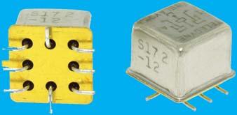
24 COMMERCIAL SURFACE-MOUNT RELAYS Series S & S Electromechanical Relays The Series S Surface Mount Centigrid Relay is an ultraminiature, hermetically sealed, armature relay. The low profi le height.0 (. mm) and.00 (. mm) lead spacing make it ideal for applications where extreme packaging density and/or close PC board spacing are required. The specially formed leads are pre-tinned to make the relays ideal for most types of surface mount solder refl ow processes. The basic design and internal construction are identical to the Series & Centigrid relays, and are capable of meeting Teledyne Relays TR requirements. The SD and SDD relays have internal discrete silicon diodes for coil suppression and polarity reversal protection. The sensitive S surface mount Centigrid Relay has a high resistance coil, thus requiring extremely low operating power (00 mw typical). The advantages of reduced heat dissipation and power supply demands are a plus. All welded construction Unique uni-frame design providing high magnetic effi ciency and mechanical rigidity 0 Million Cycle Life High force/mass ratio for resistance to shock and vibration Precious metal alloy contact material with gold plating assures excellent high current and dry circuit switching capabilities Nominal Coil COMMERCIAL SURFACE-MOUNT DPDT Non-Latching Coil Type S = Standard Coil S = Sensitive Coil Diode Options D = Internal diode for coil transient suppression DD = Internal diode for coil transient suppression and polarity reversal protection Vibration Shock 0 g s to 000 g s msec, Hz half-sine Acceleration 0 g s Temperature Storage: C to + C Operating: C to + C S SD SDD S SD SDD Voltage Resistance (Ω) P.U.V (max.) D.O.V min. max. Contact Load Rating Resistive: A/Vdc. 0.. Inductive: 00mA/Vdc (0mH) Lamp: 00mA/Vdc Low Level: 0 to 0 ua/0 to 0 mv Resistive: A/Vdc Inductive: 00mA/Vdc (0mH) Lamp: 00mA/Vdc Low Level: 0 to 0 ua/0 to 0 mv Resistive: A/Vdc Inductive: 00mA/Vdc (0mH) Lamp: 00mA/Vdc Low Level: 0 to 0 ua/0 to 0 mv Resistive: A/Vdc Inductive: 00mA/Vdc (0mH) Lamp: 00mA/Vdc Low Level: 0 to 0 ua/0 to 0 mv S S SD SD SDD SDD Schematics as viewed from terminals Page (00) (0) 0 TELEDYNE RELAYS
25 COMMERCIAL SURFACE-MOUNT RELAYS Series S Electromechanical Relays The S surface mount Centigrid relay is an ultraminiature, hermetically sealed, armature relay for commercial applications. Its low profi le height.0 (. mm) and.00 (. mm) grid spaced terminals make it an ideal choice where extreme packaging density and/or close PC board spacing are required. The specially formed surface-mount leads are pre-tinned to make the relays ideal for all types of surface-mount solder refl ow processes. The basic design and internal structure are similar to Teledyne s DPDT Centigrid relay. (see page ) The SD relay has an internal discrete silicon diode for coil transient suppression. All welded construction Unique uni-frame design providing high magnetic effi ciency and mechanical rigidity High force/mass ratio for resistance to shock and vibration Precious metal alloy contact material with gold plating assures excellent high current and dry circuit switching capabilities Million Cycle Life DPDT Non-Latching Diode Options D = Internal diode for coil transient suppression Vibration Shock 0 g s msec, 0 g s to 00 Hz half-sine Temperature Storage: C to + C Operating: C to + C S SD Voltage Series S Electromechanical Relays The magnetic-latching TO- relay, originally conceived and developed by Teledyne, has become one of the industry standards for low-level switching from dry circuit to ampere. Designed for high-density PC board surface mounting, its small size and low coil power dissipation make the S relay one of the most versatile ultraminiature relays available. The Series SD and SDD utilize discrete diodes for coil suppression and polarity reversal protection. The Series S magnetic-latching relays are ideally suited for applications where power dissipation must be minimized. The relays can be operated with a short duration pulse. After the contacts have transferred, no external holding power is required. The magnetic-latching feature of the Series S relays provide a memory capability, since the relays will not reset upon removal of coil power. S Nominal Coil Resistance (Ω) P.U.V (max.) Operating Power (mw) SD Contact Load Rating. 0 Resistive: A/Vdc Inductive: 00mA/Vdc (0mH) Lamp: 00mA/Vdc Low Level: 0 to 0 ua/0 to 0 mv All welded construction Unique uni-frame design providing high magnetic effi ciency and mechanical rigidity High force/mass ratio for resistance to shock and vibration Precious metal alloy contact material with gold plating assures excellent high current and dry circuit switching capabilities 0 Million Cycle Life COMMERCIAL SURFACE-MOUNT DPDT Magnetic-Latching Diode Options D = Internal diode for coil transient suppression DD = Internal diode for coil transient suppression and polarity reversal protection Vibration Shock 0 g s msec, 0 g s to 00 Hz half-sine Temperature Storage: C to + C Operating: C to + C Schematics as viewed from terminals COIL B S SD SDD 0 COIL A Voltage S Nominal Coil Resistance (Ω) Set & Reset Voltage SD Contact Load Rating. Resistive: A/Vdc 0. Inductive: 00mA/Vdc (0mH) 0. Lamp: 00mA/Vdc 00.0 Low Level: 0 to 0 ua/0 to 0 mv Resistive: A/Vdc. Inductive: 00mA/Vdc (0mH) 0. Lamp: 00mA/Vdc Low Level: 0 to 0 ua/0 to 0 mv COIL B 0 COIL A COIL B 0 COIL A SDD SCHEMATIC (Coil A Last Energized) SCHEMATIC (Coil A Last Energized) SCHEMATIC (Coil A Last Energized) 0 TELEDYNE RELAYS SPECIFICATIONS SUBJECT TO CHANGE WITHOUT NOTICE Page
26 ESTABLISHED RELIABILITY T R RELAYS Series ER Electromechanical Relays The Series ER Centigrid relay is an ultraminiature, hermetically sealed, armature relay. Its low profi le height. ( mm) and.00 (. mm) grid spaced terminals, which precludes the need for spreader pads, make it ideal for applications where extreme packaging density and/or close PC board spacing are required. The basic design and internal construction are similar to the standard Teledyne DPDT TO- relay (e.g., Series ER). The Series ERD and ERDD relays have internal discrete silicon diodes for coil suppression and polarity reversal protection. By virtue of its inherently low intercontact capacitance and contact circuit losses, the ER relay has proven to be an excellent ultraminiature RF switch for frequency ranges well into the UHF spectrum. A typical RF application for the ER relay is in handheld radio transceivers, wherein the combined features of good RF performance, small size, low coil power dissipation and high reliability make it a preferred method of Transmit-Receive switching. All welded construction Unique uni-frame design providing high magnetic effi ciency and mechanical rigidity High force/mass ratio for resistance to shock and vibration Precious metal alloy contact material with gold plating assures excellent high current and dry circuit switching capabilities 0 Million Cycle Life DPDT Non-Latching Diode Options D = Internal diode for coil transient suppression DD = Internal diode for coil transient suppression and polarity reversal protection Vibration Shock 0 g s g s msec, to 000 Hz half-sine Acceleration Temperature 0 g s Operating & Storage: C to + C ER ERD ERDD Voltage Resistance (Ω) Nominal Coil P.U.V (max.) D.O.V min. max. Contact Load Rating Resistive: A/Vdc. 0.. Inductive: 00mA/Vdc (0mH) Lamp: 00mA/Vdc Low Level: 0 to 0 ua/0 to 0 mv Resistive: A/Vdc Inductive: 00mA/Vdc (0mH) Lamp: 00mA/Vdc Low Level: 0 to 0 ua/0 to 0 mv ESTABLISHED RELIABILITY Series ERC Electromechanical Relays The ERC Centigrid relay is an ultraminiature, hermetically sealed, armature relay capable of being directly driven by most IC logic families. Its low profi le height and.00 (. mm) grid spaced terminals, which preclude the need for spreader pads, make it ideal for applications where extreme packaging density and/or close PC board spacing are required. The Series ERC utilizes an internal silicon diode for coil suppression, a Zener diode to protect the MOSFET gate input, and an N-channel enhancement mode MOSFET chip, which enables direct relay interfacing with most Microprocessor and IC logic families (CMOS, TTL and MOS). DPDT Non-Latching CMOS Feature Internal power MOSFET driver, Zener diode gate protection, and diode coil suppression Vibration Shock 0 g s g s msec, to 000 Hz half-sine Acceleration Temperature 0 g s Operating & Storage: C to + C ERC Voltage Nominal Coil Coil Current (ma) Min. Max. Operating Power (mw) P.U.V (max.) All welded construction Unique uni-frame design providing high magnetic effi ciency and mechanical rigidity High force/mass ratio for resistance to shock and vibration 0 Million Cycle Life Contact Load Rating...0 Resistive: A/Vdc 0... Inductive: 00mA/Vdc (0mH)... Lamp: 00mA/Vdc... Low Level: 0 to 0 ua/0 to 0 mv PIN : + SUPPLY PIN : SUPPLY PIN 0: GATE ER ERD ERDD ERC P.U.V = Pick-Up Voltage Schematics as viewed from terminals Page (00) (0) 0 TELEDYNE RELAYS
27 ESTABLISHED RELIABILITY T R RELAYS Series ER Electromechanical Relays The ER sensitive Centigrid relay retains the same features as the ER standard Centigrid relay with only a minimal increase in profi le height. (. mm). Its.00 (. mm) grid spaced terminals, which preclude the need for spreader pads, and its low profi le make the ER relay ideal for applications where high packaging density is important.the Series ERD and ERDD have internal discrete silicon diodes for coil suppression and polarity reversal protection. The sensitive ER Centigrid relay has a high resistance coil, thus requiring extremely low operating power (00 mw typical). The advantages of reduced heat dissipation and power supply demands are a plus. All welded construction Unique uni-frame design providing high magnetic effi ciency and mechanical rigidity High force/mass ratio for resistance to shock and vibration Precious metal alloy contact material with gold plating assures excellent high current and dry circuit switching capabilities 0 Million Cycle Life DPDT Non-Latching Diode Options D = Internal diode for coil transient suppression DD = Internal diode for coil transient suppression and polarity reversal protection Vibration Shock 0 g s g s msec, to 000 Hz half-sine Acceleration Temperature 0 g s Operating & Storage: C to + C ER ERD ERDD Voltage Resistance (Ω) Nominal Coil P.U.V (max.) D.O.V min. max. Contact Load Rating Resistive: A/Vdc Inductive: 00mA/Vdc (0mH) Lamp: 00mA/Vdc Low Level: 0 to 0 ua/0 to 0 mv Resistive: A/Vdc Inductive: 00mA/Vdc (0mH) Lamp: 00mA/Vdc Low Level: 0 to 0 ua/0 to 0 mv Series ERC Electromechanical Relays The sensitive ERC Centigrid relay is an ultraminiature, hermetically sealed, armature relay capable of being directly driven by most IC logic families. Its low profi le height and.00 (. mm) grid spaced terminals, which precludes the need for spreader pads, make it ideal for applications where extreme packaging density and/or close PC board spacing are required. The sensitive ERC Centigrid relay has a high resistance coil, thus requiring extremely low operating power (00 mw, typical). The advantages of reduced heat dissipation and power supply demands are a plus. The sensitive Series ERC utilizes an internal silicon diode for coil suppression, a Zener diode to protect the MOSFET gate input, and an N-channel enhancement-mode MOSFET chip that enables direct relay interfacing with most microprocessor and IC logic families (CMOS, TTL and MOS). DPDT Non-Latching CMOS Feature Internal power MOSFET driver, Zener diode gate protection, and diode coil suppression Vibration Shock 0 g s g s msec, to 000 Hz half-sine Acceleration Temperature 0 g s Operating & Storage: C to + C ERC Voltage Nominal Coil Coil Current (ma) Min. Max. Operating Power (mw) P.U.V (max.) All welded construction Unique uni-frame design providing high magnetic effi ciency and mechanical rigidity High force/mass ratio for resistance to shock and vibration 0 Million Cycle Life Contact Load Rating Resistive: A/Vdc Inductive: 00mA/Vdc (0mH).. 0. Lamp: 00mA/Vdc.. 0. Low Level: 0 to 0 ua/0 to 0 mv PIN : + SUPPLY PIN : SUPPLY PIN 0: GATE ESTABLISHED RELIABILITY ER ERD ERDD ERC Schematics as viewed from terminals P.U.V = Pick-Up Voltage D.O.V = Drop-Out Voltage 0 TELEDYNE RELAYS SPECIFICATIONS SUBJECT TO CHANGE WITHOUT NOTICE Page
28 ESTABLISHED RELIABILITY T R RELAYS Series ER & ER Electromechanical Relays The TO- relay, originally conceived and developed by Teledyne, has become one of the industry standards for low-level switching from dry circuit to ampere. Designed specifi cally for high-density PC board mounting, its small size and low coil power dissipation make the ER relay one of the most versatile ultraminiature relays available. The Series ERD and ERDD relays have internal discrete silicon diodes for coil suppression and polarity reversal protection. The hybrid ERT relay features an internal silicon suppression diode and transistor driver. This hybrid package reduces required PC board fl oor space by reducing the number of external components needed to drive the relay. The sensitive ER relay has a high resistance coil, thus requiring extremely low operating power (0 mw typical). The advantages of reduced heat dissipation and power supply demands are a plus. The Series ERD and ERDD relays have internal discrete silicon diodes for coil suppression and polarity reversal protection. The hybrid ERT relay features an internal silicon suppression diode and transistor driver. This hybrid package reduces required PC board fl oor space by minimizing the number of external components needed to drive the relay. All welded construction Unique uni-frame design providing high magnetic effi ciency and mechanical rigidity High force/mass ratio for resistance to shock and vibration Precious metal alloy contact material with gold plating assures excellent high current and dry circuit switching capabilities 0 Million Cycle Life Nominal Coil ESTABLISHED RELIABILITY SPDT Non-Latching Coil Type ER = Standard Coil ER = Sensitive Coil Diode Options D = Internal diode for coil transient suppression DD = Internal diode for coil transient suppression and polarity reversal protection T = Internal transistor drive and coil transient suppression diode Vibration Shock 0 g s g s msec, to 000 Hz half-sine Acceleration Temperature 0 g s Operating & Storage: C to + C ER ER ERD ERD ERDD ERDD ER ERD ERDD ERT ER ERD ERDD ERT Voltage Resistance (Ω) P.U.V (max.) D.O.V min. max. Contact Load Rating. 0.. Resistive: A/Vdc. 0.. Inductive: 00mA/Vdc (0mH) Lamp: 00mA/Vdc Low Level: 0 to 0 ua/0 to 0 mv Resistive: A/Vdc. 0.. Inductive: 00mA/Vdc (0mH) Lamp: 00mA/Vdc Low Level: 0 to 0 ua/0 to 0 mv Resistive: A/Vdc. 0.. Inductive: 00mA/Vdc (0mH) Lamp: 00mA/Vdc Low Level: 0 to 0 ua/0 to 0 mv Resistive: A/Vdc. 0.. Inductive: 00mA/Vdc (0mH) Lamp: 00mA/Vdc Low Level: 0 to 0 ua/0 to 0 mv Resistive: A/Vdc Inductive: 00mA/Vdc (0mH) Lamp: 00mA/Vdc Low Level: 0 to 0 ua/0 to 0 mv Resistive: A/Vdc. 0.. Inductive: 00mA/Vdc (0mH) Lamp: 00mA/Vdc Low Level: 0 to 0 ua/0 to 0 mv ERT ERT Schematics as viewed from terminals P.U.V = Pick-Up Voltage D.O.V = Drop-Out Voltage Page (00) (0) 0 TELEDYNE RELAYS
29 ESTABLISHED RELIABILITY T R RELAYS Series ER & ER Electromechanical Relays The TO- relay, originally conceived and developed by Teledyne, has become one of the industry standards for low-level switching from dry circuit to ampere. Designed specifi cally for high-density PC board mounting, its small size and low coil power dissipation make the ER relay one of the most versatile ultraminiature relays available. The Series ERD and ERDD relays have internal discrete silicon diodes for coil suppression and polarity reversal protection. The hybrid ERT relay features an internal silicon suppression diode and transistor driver. This hybrid package reduces required PC board fl oor space by reducing the number of external components needed to drive the relay. The sensitive ER relay has a high resistance coil, thus requiring extremely low operating power (00 mw typical). The advantages of reduced heat dissipation and power supply demands are a plus. The Series ERD and ERDD relays have internal discrete silicon diodes for coil suppression and polarity reversal protection. The hybrid ERT relay features an internal silicon suppression diode and transistor driver. This hybrid package reduces required PC board fl oor space by minimizing the number of external components needed to drive the relay. All welded construction Unique uni-frame design providing high magnetic effi ciency and mechanical rigidity High force/mass ratio for resistance to shock and vibration Precious metal alloy contact material with gold plating assures excellent high current and dry circuit switching capabilities 0 Million Cycle Life DPDT Non-Latching Coil Type ER = Standard Coil ER = Sensitive Coil Diode Options D = Internal diode for coil transient suppression DD = Internal diode for coil transient suppression and polarity reversal protection T = Internal transistor drive and coil transient suppression diode Vibration Shock 0 g s g s msec, to 000 Hz half-sine Acceleration Temperature 0 g s 0 Operating & Storage: C to + C ER ER ERD ERD ERDD ERDD ERT ERT ER ERD ERDD ERT ER ERD ERDD ERT Voltage Schematics as viewed from terminals Resistance (Ω) Nominal Coil P.U.V (max.) D.O.V min. max. Contact Load Rating Resistive: A/Vdc. 0.. Inductive: 00mA/Vdc (0mH) Lamp: 00mA/Vdc Low Level: 0 to 0 ua/0 to 0 ua Resistive: A/Vdc. 0.. Inductive: 00mA/Vdc (0mH) Lamp: 00mA/Vdc Low Level: 0 to 0 ua/0 to 0 ua Resistive: A/Vdc. 0.. Inductive: 00mA/Vdc (0mH) Lamp: 00mA/Vdc Low Level: 0 to 0 ua/0 to 0 mv Resistive: A/Vdc Inductive: 00mA/Vdc (0mH) Lamp: 00mA/Vdc Low Level: 0 to 0 ua/0 to 0 mv Resistive: A/Vdc Inductive: 00mA/Vdc (0mH) Lamp: 00mA/Vdc Low Level: 0 to 0 ua/0 to 0 mv Resistive: A/Vdc Inductive: 00mA/Vdc (0mH) Lamp: 00mA/Vdc Low Level: 0 to 0 ua/0 to 0 mv P.U.V = Pick-Up Voltage D.O.V = Drop-Out Voltage ESTABLISHED RELIABILITY 0 TELEDYNE RELAYS SPECIFICATIONS SUBJECT TO CHANGE WITHOUT NOTICE Page
30 ESTABLISHED RELIABILITY T R RELAYS Series, Electromechanical Relays The Series is an industry-standard, half-size, latching crystal can relay. It has a wide range of switching capabilities ranging from low level to amps. The Series J/ latching relay confi guration is doublepole double-throw (DPDT), so the relay offers excellent switching density and versatility. Half-Size Crystal Can Features: Low level to amps Wide range of switching capabilities Smallest relay package capable of switching amps Modernized assembly process Lead-free (gold-plated wire lead only) All welded construction Wire leads, gold-plated or solder-coated Matched seal for superior hermeticity Gold-plated contact assembly Modernized assembly process Advanced cleaning techniques Million Cycle Life Nominal Coil DPDT Magnetic-Latching Vibration 0G, 0-00 Hz (Sinusoidal) Shock 00G, msec half-sine (Specifi ed Pulse) Temperature Operating & Storage: C to + C Voltage B A A X Resistance (Ω) Set & Reset Voltage Min. Max. B A A X Contact Load Rating.0. Resistive: A/Vdc.. Inductive: 0.A/Vdc (0mH)..0 Intermediate Current: 0.A/Vdc Lamp: 0.A/Vdc Low Level: 0 to 0 ua/0 to 0 mv Y X Y X Y Y B B A B B A ESTABLISHED RELIABILITY Series ER Electromechanical Relays The magnetic-latching TO- relay, originally conceived and developed by Teledyne, has become one of the industry standards for low-level switching from dry circuit to ampere. Designed for high-density PC board mounting, its small size and low coil power dissipation make the ER relay one of the most versatile ultraminiature relays available. The Series ERD and ERDD utilize discrete silicon diodes for coil suppression and polarity reversal protection. The Series ER magnetic-latching relays are ideally suited for applications where coil power dissipation must be minimized. The relays can be operated with a short duration pulse. After the contacts have transferred, no external holding power is required. The magnetic-latching feature of the Series ER provides a memory capability, since the relays will not reset upon removal of coil power. SPDT Magnetic-Latching Diode Options D = Internal diode for coil transient suppression DD = Internal diode for coil transient suppression and polarity reversal protection Vibration Shock 0 g s 00 g s msec, to 000 Hz half-sine Acceleration Temperature 0 g s Operating & Storage: C to + C *See Schematics on Page ER ERD ERDD SCHEMATIC (Coil X Last Energized) (Bottom View) Voltage Nominal Coil Resistance (Ω) SCHEMATIC (Coil X Last Energized) (Bottom View) Set & Reset Voltage All welded construction Unique uni-frame design providing high magnetic effi ciency and mechanical rigidity High force/mass ratio for resistance to shock and vibration Precious metal alloy contact material with gold plating assures excellent high current and dry circuit switching capabilities 0 Million Cycle Life Contact Load Rating. Resistive: A/Vdc 0. Inductive: 00mA/Vdc (0mH) 0. Lamp: 00mA/Vdc 00.0 Low Level: 0 to 0 ua/0 to 0 mv Resistive: A/Vdc 0. Inductive: 00mA/Vdc (0mH) 0. Lamp: 00mA/Vdc 00.0 Low Level: 0 to 0 ua/0 to 0 mv Resistive: A/Vdc. Inductive: 00mA/Vdc (0mH) 0. Lamp: 00mA/Vdc Low Level: 0 to 0 ua/0 to 0 mv Page (00) (0) 0 TELEDYNE RELAYS
31 ESTABLISHED RELIABILITY T R RELAYS Series ER0 & ER Electromechanical Relays The magnetic-latching TO- relay, originally conceived and developed by Teledyne, has become one of the industry standards for low-level switching from dry circuit to ampere. Designed for high-density PC board mounting, its small size and low coil power dissipation make the ER0 & ER relays some of the most versatile ultraminiature relays available. The Series ER0D/ERD and ER0DD/ERDD utilize discrete silicon diodes for coil suppression and polarity reversal protection. The Series ER0/ER magnetic-latching relays are ideally suited for applications where coil power dissipation must be minimized. The relays can be operated with a short duration pulse. After the contacts have transferred, no external holding power is required. The magnetic-latching feature of the Series ER0/ ER relays provide a memory capability, since the relays will not reset upon removal of coil power. All welded construction Unique uni-frame design providing high magnetic effi ciency and mechanical rigidity High force/mass ratio for resistance to shock and vibration Precious metal alloy contact material with gold plating assures excellent high current and dry circuit switching capabilities 0 Million Cycle Life DPDT Magnetic-Latching Grounding Options 0 = Common = Individual Diode Options D = Internal diode for coil transient suppression DD = Internal diode for coil transient suppression and polarity reversal protection Vibration Shock 0 g s 00 g s msec, to 000 Hz half-sine Acceleration Temperature 0 g s Operating & Storage: C to + C COIL B ER0 ER ER0D ERD ER0DD ERDD COIL A Voltage Nominal Coil Resistance (Ω) Set & Reset Voltage Contact Load Rating. Resistive: A/Vdc 0. Inductive: 00mA/Vdc (0mH) 0. Lamp: 00mA/Vdc 00.0 Low Level: 0 to 0 ua/0 to 0 mv Resistive: A/Vdc. Inductive: 00mA/Vdc (0mH) 0. Lamp: 00mA/Vdc Low Level: 0 to 0 ua/0 to 0 mv COIL B COIL A COIL B ER0 ER0D ER0DD COIL A ESTABLISHED RELIABILITY COIL A COIL B COIL B COIL A COIL B COIL A ER ERD ERDD COIL B COIL B COIL B COIL A COIL A ER ERD ERDD COIL A Schematics Shown with Coil A Last Energized Schematics as viewed from terminals 0 TELEDYNE RELAYS SPECIFICATIONS SUBJECT TO CHANGE WITHOUT NOTICE Page
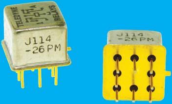
32 MILITARY QUALIFIED (JAN) RELAYS Series J Electromechanical Relays The Series J Centigrid relay is an ultraminiature, hermetically sealed, armature relay. Its low profi le height. ( mm) and.00 (. mm) grid spaced terminals, which precludes the need for spreader pads, make it ideal for applications where extreme packaging density and/or close PC board spacing are required. The basic design and internal construction are similar to the standard Teledyne DPDT TO- relay (e.g., Series J). The Series JD and JDD relays have internal discrete silicon diodes for coil suppression and polarity reversal protection. By virtue of its inherently low intercontact capacitance and contact circuit losses, the J relay has proven to be an excellent ultraminiature RF switch for frequency ranges well into the UHF spectrum. A typical RF application for the J relay is in handheld radio transceivers, wherein the combined features of good RF performance, small size, low coil power dissipation and high reliability make it a preferred method of Transmit-Receive switching. All welded construction Unique uni-frame design providing high magnetic effi ciency and mechanical rigidity High force/mass ratio for resistance to shock and vibration Precious metal alloy contact material with gold plating assures excellent high current and dry circuit switching capabilities 0 Million Cycle Life DPDT Non-Latching Diode Options D = Internal diode for coil transient suppression DD = Internal diode for coil transient suppression and polarity reversal protection Vibration Shock 0 g s g s msec, to 000 Hz half-sine Acceleration Temperature 0 g s Operating & Storage: C to + C J (M0/) JD (M0/) JDD (M0/) Voltage Resistance (Ω) Nominal Coil P.U.V (max.) D.O.V min. max. Contact Load Rating Resistive: A/Vdc. 0.. Inductive: 00mA/Vdc (0mH) Lamp: 00mA/Vdc Low Level: 0 to 0 ua/0 to 0 mv Resistive: A/Vdc Inductive: 00mA/Vdc (0mH) Lamp: 00mA/Vdc Low Level: 0 to 0 ua/0 to 0 mv MILITARY QUALIFIED (JAN) Series JC Electromechanical Relays The JC Centigrid relay is an ultraminiature, hermetically sealed, armature relay capable of being directly driven by most IC logic families. Its low profi le height and.00 (. mm) grid spaced terminals, which preclude the need for spreader pads, make it ideal for applications where extreme packaging density and/or close PC board spacing are required. The Series JC utilizes an internal silicon diode for coil suppression, a Zener diode to protect the MOSFET gate input, and an N-channel enhancement mode MOSFET chip, which enables direct relay interfacing with most Microprocessor and IC logic families (CMOS, TTL and MOS). DPDT Non-Latching CMOS Feature Internal power MOSFET driver, Zener diode gate protection, and diode coil suppression Vibration Shock 0 g s g s msec, to 000 Hz half-sine Acceleration Temperature JC (M/) Voltage Nominal Coil Coil Current (ma) Min. Max. Operating Power (mw) P.U.V (max.) All welded construction Unique uni-frame design providing high magnetic effi ciency and mechanical rigidity High force/mass ratio for resistance to shock and vibration 0 Million Cycle Life Contact Load Rating...0 Resistive: A/Vdc 0... Inductive: 00mA/Vdc (0mH)... Lamp: 00mA/Vdc... Low Level: 0 to 0 ua/0 to 0 mv g s P.U.V = Pick-Up Voltage D.O.V = Drop-Out Voltage Operating & Storage: C to + C Schematics as viewed from terminals 0 + J JD JDD JC PIN : + SUPPLY PIN : SUPPLY PIN 0: GATE Page 0 (00) (0) 0 TELEDYNE RELAYS
33 MILITARY QUALIFIED (JAN) RELAYS Series J Electromechanical Relays The J sensitive Centigrid relay retains the same features as the J standard Centigrid relay with only a minimal increase in profi le height. (. mm). Its.00 (. mm) grid spaced terminals, which preclude the need for spreader pads, and its low profi le make the J relay ideal for applications where high packaging density is important. The Series JD and JDD have internal discrete silicon diodes for coil suppression and polarity reversal protection. The sensitive J Centigrid relay has a high resistance coil, thus requiring extremely low operating power (00 mw typical). The advantages of reduced heat dissipation and power supply demands are a plus. All welded construction Unique uni-frame design providing high magnetic effi ciency and mechanical rigidity High force/mass ratio for resistance to shock and vibration Precious metal alloy contact material with gold plating assures excellent high current and dry circuit switching capabilities 0 Million Cycle Life DPDT Non-Latching Diode Options D = Internal diode for coil transient suppression DD = Internal diode for coil transient suppression and polarity reversal protection Vibration Shock 0 g s g s msec, to 000 Hz half-sine Acceleration Temperature 0 g s Operating & Storage: C to + C J (M0/) JD (M0/) JDD (M0/) Voltage Resistance (Ω) Nominal Coil P.U.V (max.) D.O.V min. max. Contact Load Rating Resistive: A/Vdc Inductive: 00mA/Vdc (0mH) Lamp: 00mA/Vdc Low Level: 0 to 0 ua/0 to 0 mv Resistive: A/Vdc Inductive: 00mA/Vdc (0mH) Lamp: 00mA/Vdc Low Level: 0 to 0 ua/0 to 0 mv Series JC Electromechanical Relays The sensitive JC Centigrid relay is an ultraminiature, hermetically sealed, armature relay capable of being directly driven by most IC logic families. Its low profi le height and.00 (. mm) grid spaced terminals, which precludes the need for spreader pads, make it ideal for applications where extreme packaging density and/or close PC board spacing are required. The sensitive JC Centigrid relay has a high resistance coil, thus requiring extremely low operating power (00 mw, typical). The advantages of reduced heat dissipation and power supply demands are a plus. The sensitive Series JC utilizes an internal silicon diode for coil suppression, a Zener diode to protect the MOSFET gate input, and an N-channel enhancement-mode MOSFET chip that enables direct relay interfacing with most microprocessor and IC logic families (CMOS, TTL and MOS). DPDT Non-Latching CMOS Feature Internal power MOSFET driver, Zener diode gate protection, and diode coil suppression Vibration Shock 0 g s g s msec, to 000 Hz half-sine Acceleration Temperature 0 g s Operating & Storage: C to + C JC (M/) Voltage Nominal Coil Coil Current (ma) Min. Max. Operating Power (m W ) P.U.V (max.) All welded construction Unique uni-frame design providing high magnetic effi ciency and mechanical rigidity High force/mass ratio for resistance to shock and vibration Precious metal alloy contact material with gold plating assures excellent high current and dry circuit switching capabilities 0 Million Cycle Life Contact Load Rating Resistive: A/Vdc Inductive: 00mA/Vdc (0mH).. 0. Lamp: 00mA/Vdc.. 0. Low Level: 0 to 0 ua/0 to 0 mv PIN : + SUPPLY PIN : SUPPLY PIN 0: GATE MILITARY QUALIFIED (JAN) Schematics as viewed from terminals J JD JDD JC P.U.V = Pick-Up Voltage D.O.V = Drop-Out Voltage 0 TELEDYNE RELAYS SPECIFICATIONS SUBJECT TO CHANGE WITHOUT NOTICE Page
34 MILITARY QUALIFIED (JAN) RELAYS Series J & J Electromechanical Relays The TO- relay, originally conceived and developed by Teledyne, has become one of the industry standards for low-level switching from dry circuit to ampere. Designed specifi cally for high-density PC board mounting, its small size and low coil power dissipation make the J relay one of the most versatile ultraminiature relays available. The Series JD and JDD relays have internal discrete silicon diodes for coil suppression and polarity reversal protection. The hybrid JT relay features an internal silicon suppression diode and transistor driver. This hybrid package reduces required PC board fl oor space by reducing the number of external components needed to drive the relay. The sensitive J relay has a high resistance coil, thus requiring extremely low operating power (0 mw typical). The advantages of reduced heat dissipation and power supply demands are a plus. The Series JD and JDD relays have internal discrete silicon diodes for coil suppression and polarity reversal protection. The hybrid JT relay features an internal silicon suppression diode and transistor driver. This hybrid package reduces required PC board fl oor space by reducing the number of external components needed to drive the relay. All welded construction Unique uni-frame design providing high magnetic effi ciency and mechanical rigidity High force/mass ratio for resistance to shock and vibration Precious metal alloy contact material with gold plating assures excellent high current and dry circuit switching capabilities 0 Million Cycle Life Nominal Coil MILITARY QUALIFIED (JAN) SPDT Non-Latching Coil Type J = Standard Coil J = Sensitive Coil Diode Options D = Internal diode for coil transient suppression DD = Internal diode for coil transient suppression and polarity reversal protection T = Internal transistor drive and coil transient suppression diode Vibration Shock 0 g s g s msec, to 000 Hz half-sine Acceleration Temperature 0 g s Operating & Storage: C to + C J J JD JD JDD JDD J (M0/) JD (M0/) JDD (M0/) JT (M/) J (M0/0) JD (M0/) JDD (M0/) JT (M/) Voltage Resistance (Ω) P.U.V (max.) D.O.V min. max. Contact Load Rating. 0.. Resistive: A/Vdc. 0.. Inductive: 00mA/Vdc (0mH) Lamp: 00mA/Vdc Low Level: 0 to 0 ua/0 to 0 mv Resistive: A/Vdc. 0.. Inductive: 00mA/Vdc (0mH) Lamp: 00mA/Vdc Low Level: 0 to 0 ua/0 to 0 mv Resistive: A/Vdc. 0.. Inductive: 00mA/Vdc (0mH) Lamp: 00mA/Vdc Low Level: 0 to 0 ua/0 to 0 mv Resistive: A/Vdc. 0.. Inductive: 00mA/Vdc (0mH) Lamp: 00mA/Vdc Low Level: 0 to 0 ua/0 to 0 mv Resistive: A/Vdc Inductive: 00mA/Vdc (0mH) Lamp: 00mA/Vdc Low Level: 0 to 0 ua/0 to 0 mv Resistive: A/Vdc. 0.. Inductive: 00mA/Vdc (0mH) Lamp: 00mA/Vdc Low Level: 0 to 0 ua/0 to 0 mv JT JT P.U.V = Pick-Up Voltage D.O.V = Drop-Out Voltage Schematics as viewed from terminals Page (00) (0) 0 TELEDYNE RELAYS
35 MILITARY QUALIFIED (JAN) RELAYS Series J & J Electromechanical Relays The TO- relay, originally conceived and developed by Teledyne, has become one of the industry standards for lowlevel switching from dry circuit to ampere. Designed specifi cally for high-density PC board mounting, its small size and low coil power dissipation make the J relay one of the most versatile ultraminiature relays available. The Series JD and JDD relays have internal discrete silicon diodes for coil suppression and polarity reversal protection. The hybrid JT relay features an internal silicon suppression diode and transistor driver. This hybrid package reduces required PC board fl oor space by reducing the number of external components needed to drive the relay. The sensitive J relay has a high resistance coil, thus requiring extremely low operating power (00 mw typical). The advantages of reduced heat dissipation and power supply demands are a plus. The Series JD and JDD relays have internal discrete silicon diodes for coil suppression and polarity reversal protection. The hybrid JT relay features an internal silicon suppression diode and transistor driver. This hybrid package reduces required PC board fl oor space by reducing the number of external components needed to drive the relay. All welded construction Unique uni-frame design providing high magnetic effi ciency and mechanical rigidity High force/mass ratio for resistance to shock and vibration Precious metal alloy contact material with gold plating assures excellent high current and dry circuit switching capabilities 0 Million Cycle Life DPDT Non-Latching Coil Type J = Standard Coil J = Sensitive Coil Diode Options D = Internal diode for coil transient suppression DD = Internal diode for coil transient suppression and polarity reversal protection T = Internal transistor drive and coil transient suppression diode Vibration Shock 0 g s g s msec, to 000 Hz half-sine Acceleration Temperature 0 g s Operating & Storage: C to + C J J JD JD JDD JDD J (M0/) JD (M0/) JDD (M0/0) JT (M/) J (M0/) JD (M0/) JDD (M0/) JT (M/) Voltage Resistance (Ω) Nominal Coil P.U.V (max.) D.O.V min. max. Contact Load Rating Resistive: A/Vdc. 0.. Inductive: 00mA/Vdc (0mH) Lamp: 00mA/Vdc Low Level: 0 to 0 ua/0 to 0 ua Resistive: A/Vdc. 0.. Inductive: 00mA/Vdc (0mH) Lamp: 00mA/Vdc Low Level: 0 to 0 ua/0 to 0 ua Resistive: A/Vdc. 0.. Inductive: 00mA/Vdc (0mH) Lamp: 00mA/Vdc Low Level: 0 to 0 ua/0 to 0 mv Resistive: A/Vdc Inductive: 00mA/Vdc (0mH) Lamp: 00mA/Vdc Low Level: 0 to 0 ua/0 to 0 mv Resistive: A/Vdc Inductive: 00mA/Vdc (0mH) Lamp: 00mA/Vdc Low Level: 0 to 0 ua/0 to 0 mv Resistive: A/Vdc Inductive: 00mA/Vdc (0mH) Lamp: 00mA/Vdc Low Level: 0 to 0 ua/0 to 0 mv MILITARY QUALIFIED (JAN) 0 JT JT Schematics as viewed from terminals P.U.V = Pick-Up Voltage D.O.V = Drop-Out Voltage 0 TELEDYNE RELAYS SPECIFICATIONS SUBJECT TO CHANGE WITHOUT NOTICE Page
36 MILITARY QUALIFIED (JAN) RELAYS Series J Electromechanical Relays The Series J is an industry-standard, half-size, latching crystal can relay. It has a wide range of switching capabilities ranging from low level to amps. The Series J latching relay confi guration is double-pole double-throw (DPDT), so the relay offers excellent switching density and versatility. Half-Size Crystal Can Features: Low level to amps Wide range of switching capabilities Smallest relay package capable of switching amps Modernized assembly process Qualifi ed to MIL-PRF0/ Lead-free (gold-plated wire lead only) All welded construction Wire leads, gold-plated or solder-coated Matched seal for superior hermeticity Gold-plated contact assembly Modernized assembly process Advanced cleaning techniques Million Cycle Life DPDT Magnetic-Latching Vibration 0G, 0-00 Hz (Sinusoidal) Shock 00G, msec half-sine (Specifi ed Pulse) Temperature Operating & Storage: C to + C Y J (M0/) B A A X Y X Voltage J Resistance (Ω) Nominal Coil Set & Reset Voltage Min. Max. Contact Load Rating.0. Resistive: A/Vdc.. Inductive: 0.A/Vdc (0mH)..0 Intermediate Current: 0.A/Vdc Lamp: 0.A/Vdc Low Level: 0 to 0 ua/0 to 0 mv B B A SCHEMATIC (Coil X Last Energized) (Bottom View) Series J Electromechanical Relays The magnetic-latching TO- relay, originally conceived and developed by Teledyne, has become one of the industry standards for low-level switching from dry circuit to ampere. Designed for high-density PC board mounting, its small size and low coil power dissipation make the J relay one of the most versatile ultraminiature relays available. The Series JD and JDD utilize discrete silicon diodes for coil suppression and polarity reversal protection. The Series J magnetic-latching relays are ideally suited for applications where coil power dissipation must be minimized. The relays can be operated with a short duration pulse. After the contacts have transferred, no external holding power is required. The magnetic-latching feature of the Series J provides a memory capability, since the relays will not reset upon removal of coil power. All welded construction Unique uni-frame design providing high magnetic effi ciency and mechanical rigidity High force/mass ratio for resistance to shock and vibration Precious metal alloy contact material with gold plating assures excellent high current and dry circuit switching capabilities 0 Million Cycle Life MILITARY QUALIFIED (JAN) SPDT Magnetic-Latching Diode Options D = Internal diode for coil transient suppression DD = Internal diode for coil transient suppression and polarity reversal protection Vibration Shock 0 g s 00 g s msec, to 000 Hz half-sine Acceleration Temperature 0 g s *See Schematics on Page Operating & Storage: C to + C J (M0/) JD (M0/) JDD (M0/) Voltage Nominal Coil Resistance (Ω) Set & Reset Voltage Contact Load Rating. Resistive: A/Vdc 0. Inductive: 00mA/Vdc (0mH) 0. Lamp: 00mA/Vdc 00.0 Low Level: 0 to 0 ua/0 to 0 mv Resistive: A/Vdc 0. Inductive: 00mA/Vdc (0mH) 0. Lamp: 00mA/Vdc 00.0 Low Level: 0 to 0 ua/0 to 0 mv Resistive: A/Vdc. Inductive: 00mA/Vdc (0mH) 0. Lamp: 00mA/Vdc Low Level: 0 to 0 ua/0 to 0 mv Page (00) (0) 0 TELEDYNE RELAYS
37 MILITARY QUALIFIED (JAN) RELAYS Series J0 & J Electromechanical Relays The magnetic-latching TO- relay, originally conceived and developed by Teledyne, has become one of the industry standards for low-level switching from dry circuit to ampere. Designed for high-density PC board mounting, its small size and low coil power dissipation make the J0 & J relays some of the most versatile ultraminiature relays available. The Series J0D/JD and J0DD/JDD utilize discrete silicon diodes for coil suppression and polarity reversal protection. The Series J0/J magnetic-latching relays are ideally suited for applications where coil power dissipation must be minimized. The relays can be operated with a short duration pulse. After the contacts have transferred, no external holding power is required. The magnetic-latching feature of the Series J0/ J relays provide a memory capability, since the relays will not reset upon removal of coil power. All welded construction Unique uni-frame design providing high magnetic effi ciency and mechanical rigidity High force/mass ratio for resistance to shock and vibration Precious metal alloy contact material with gold plating assures excellent high current and dry circuit switching capabilities 0 Million Cycle Life DPDT Magnetic-Latching Grounding Options J0 = Common J = Individual Diode Options D = Internal diode for coil transient suppression DD = Internal diode for coil transient suppression and polarity reversal protection Vibration Shock 0 g s 00 g s msec, to 000 Hz half-sine Acceleration Temperature J0 (M0/) J (M0/) J0D (M0/) JD (M0/) J0DD (M0/0) JDD (M0/0) Voltage Nominal Coil Resistance (Ω) Set & Reset Voltage Contact Load Rating. Resistive: A/Vdc 0. Inductive: 00mA/Vdc (0mH) 0. Lamp: 00mA/Vdc 00.0 Low Level: 0 to 0 ua/0 to 0 mv Resistive: A/Vdc. Inductive: 00mA/Vdc (0mH) 0. Lamp: 00mA/Vdc Low Level: 0 to 0 ua/0 to 0 mv g s Operating & Storage: C to + C COIL B COIL B COIL B COIL A COIL A COIL A J0 J0D J0DD COIL A COIL B COIL B Schematics Shown with Coil A Last Energized Schematics as viewed from terminals COIL B COIL A COIL A J JD JDD MILITARY QUALIFIED (JAN) COIL B COIL B COIL B COIL A COIL A J JD JDD COIL A 0 TELEDYNE RELAYS SPECIFICATIONS SUBJECT TO CHANGE WITHOUT NOTICE Page
38 HIGH-PERFORMANCE RELAYS Series H, H & H Electromechanical Relays - High Temperature The TO- relay, originally conceived and developed by Teledyne, has become one of the industry standards for low-level switching from dry circuit to ampere. Designed for high-density PC board mounting, these TO- relays are some of the most versatile ultraminiature relays available because of their small size and low coil power dissipation. The H Series high-temperature TO- relays are designed for reliable operation in elevated ambient temperatures up to 00 C. Special material selection and processing provide assurance of freedom from contact contamination and mechanical malfunctioning that might otherwise be caused by ultra high ambient temperature conditions. Typical applications: Oil exploration (down-hole) instrumentation High-Temperature industrial and process control instrumentation All welded construction Unique uni-frame design providing high magnetic effi ciency and mechanical rigidity High force/mass ratio for resistance to shock and vibration Precious metal alloy contact material with gold plating assures excellent high current and dry circuit switching capabilities 0 Million Cycle Life H = DPDT Non-Latching H = DPDT Non-Latching H = DPDT Magnetic- Latching Coil Type H = Standard Coil H = Standard Coil H = Sensitive Coil Vibration 0 g s to 000 Hz Shock H = g s msec, half-sine H = g s msec, half-sine H = 00 g s Acceleration 0 g s Temperature Operating & Storage: C to +00 C H H H Voltage Voltage Resistance (Ω) Nominal Coil Resistance (Ω) Nominal Coil P.U.V (max.) Set & Reset Voltage D.O.V min. max. Contact Load Rating Resistive: A/Vdc. 0.. Inductive: 00mA/Vdc (0mH) Lamp: 00mA/Vdc Low Level: 0 to 0 ua/0 to 0 mv Resistive: A/Vdc Inductive: 00mA/Vdc (0mH) Lamp: 00mA/Vdc Low Level: 0 to 0 ua/0 to 0 mv Contact Load Rating. Resistive: A/Vdc 0. Inductive: 00mA/Vdc (0mH) 0.0 Lamp: 00mA/Vdc 00. Low Level: 0 to 0 ua/0 to 0 mv COIL B 0 HIGH PERFORMANCE Schematics as viewed from terminals P.U.V = Pick-Up Voltage D.O.V = Drop-Out Voltage H H SCHEMATIC (Coil A Last Energized) H COIL A Page (00) (0) 0 TELEDYNE RELAYS
39 HIGH-PERFORMANCE RELAYS Series K & K Electromechanical Relays - High Shock The TO- relay, originally conceived and developed by Teledyne, has become one of the industry standards for low-level switching from dry circuit to ampere. Designed for high-density PC board mounting, its small size and low coil power dissipation make the TO- relay one of the most versatile subminiature relays available. The K Series high-shock TO- relays are designed to withstand shock levels up to 000 g s,. msec duration. Special material selection and construction details provide assurance that critical elements of the relay structure and mechanism will not be permanently displaced or damaged as a result of extremely high g level shocks. Typical applications: Commercial avionics aircraft control Commercial aircraft control systems Transportation systems (rail/truck) All welded construction Unique uni-frame design providing high magnetic effi ciency and mechanical rigidity High force/mass ratio for resistance to shock and vibration Precious metal alloy contact material with gold plating assures excellent high current and dry circuit switching capabilities 0 Million Cycle Life K = DPDT Non-Latching K = DPDT Magnetic- Latching Vibration 0 g s to 000 Hz Shock K = g s msec, half-sine 000 g s, 0. msec axial plane, half-sine 000 g s, 0. msec side planes, half-sine K = 00 g s msec, half-sine 00 g s, 0. msec axial plane, half-sine 0 g s, 0. msec side planes, half-sine Acceleration 0 g s Temperature Operating & Storage: C to + C K K Voltage Voltage Resistance (Ω) Nominal Coil Resistance (Ω) Nominal Coil P.U.V (max.) Set & Reset Voltage D.O.V min. max. Contact Load Rating Resistive: A/Vdc Inductive: 00mA/Vdc (0mH) Lamp: 00mA/Vdc Low Level: 0 to 0 ua/0 to 0 mv Contact Load Rating. Resistive: A/Vdc 0. Inductive: 00mA/Vdc (0mH) 0. Lamp: 00mA/Vdc 00.0 Low Level: 0 to 0 ua/0 to 0 mv COIL B 0 K COIL A SCHEMATIC (Coil A Last Energized) K Schematics as viewed from terminals P.U.V = Pick-Up Voltage D.O.V = Drop-Out Voltage HIGH PERFORMANCE 0 TELEDYNE RELAYS SPECIFICATIONS SUBJECT TO CHANGE WITHOUT NOTICE Page
40 HIGH-PERFORMANCE RELAYS Series V & V Electromechanical Relays - High Vibration The V and V TO- relays, originally conceived and developed by Teledyne, have become the industry standards for low level switching from dry circuit to ampere in high-vibration environments. Designed for high-density PC board mounting, these TO- relays are some of the most versatile ultraminiature relay available because of their small size and low coil power dissipation. The V Series high-vibration relays are designed to withstand vibration levels of 0 to 0 g s at the frequencies noted, when tested on a resonant beam for 0 to 0 seconds, in the axis parallel to contact motion (x-axis), or 00 g s Hz for 0 minutes in the x-axis. A unique magnetic circuit prevents contact opening (chatter) in excess of 0 microseconds under vibration or shock conditions. Typical applications: Avionics aircraft control Aircraft control systems Transportation systems (rail/truck) All welded construction Unique uni-frame design providing high magnetic effi ciency and mechanical rigidity High force/mass ratio for resistance to shock and vibration Precious metal alloy contact material with gold plating assures excellent high current and dry circuit switching capabilities 0 Million Cycle Life DPDT Non-Latching Coil Type V = Standard Coil V = Sensitive Coil Diode Options D = Internal diode for coil transient suppression DD = Internal diode for coil transient suppression and polarity reversal protection Vibration 0 g s at 0 ± Hz 0 g s at 0 ± Hz 0 g s at 00 ± Hz Shock 0 g s msec, half-sine Acceleration 0 g s Temperature Operating & Storage: C to + C V DV DDV V DV Voltage Resistance (Ω) Nominal Coil P.U.V (max.) D.O.V min. max. Contact Load Rating Resistive: A/Vdc Inductive: 00mA/Vdc (0mH). 0.. Lamp: 00mA/Vdc Low Level: 0 to 0 ua/0 to 0 mv Resistive: A/Vdc. 0.. Inductive: 00mA/Vdc (0mH). 0.. Lamp: 00mA/Vdc Low Level: 0 to 0 ua/0 to 0 mv Resistive: A/Vdc Inductive: 00mA/Vdc (0mH) Lamp: 00mA/Vdc Low Level: 0 to 0 ua/0 to 0 mv V V DV DV DDV HIGH PERFORMANCE Schematics as viewed from terminals P.U.V = Pick-Up Voltage D.O.V = Drop-Out Voltage Page (00) (0) 0 TELEDYNE RELAYS


41 APPENDIX: SIGNAL INTEGRITY EYE DIAGRAMS SERIES SI00 / SI0 Bit Rate Eye Height Eye Width Jitter P-P 0 Gbps mv ps 0. ps SERIES RF + mv - mv 0 ps 0 ps 0 ps 0 ps 0 ps 00 ps Bit Rate Eye Height Eye Width Jitter P-P 0 Gbps 0 mv 0. ps. ps 0 TELEDYNE RELAYS SPECIFICATIONS SUBJECT TO CHANGE WITHOUT NOTICE Page


 -00 www.")

42 APPENDIX: SIGNAL INTEGRITY EYE DIAGRAMS Gbps Gbps Bit Rate Eye Height Eye Width Jitter P-P Gbps 0 mv. ps. ps Gbps Gbps Bit Rate Eye Height Eye Width Jitter P-P Gbps. mv. ps. ps 0Gbps 0Gbps Bit Rate Eye Height Eye Width Jitter P-P 0 Gbps mv. ps. ps Page 0 (00) (0) 0 TELEDYNE RELAYS


43 APPENDIX: SIGNAL INTEGRITY EYE DIAGRAMS SERIES LB AC BYPASS (Capacitor Gbps Normally Closed Gbps +0 mv +0 mv -0 mv -0 mv 0 ps 0 ps 0 ps 0 ps 0 ps 00 ps 0 ps 0 ps 0 ps 0 ps 0 ps 00 ps Bit Rate Eye Height Eye Width Jitter P-P Gbps 0 mv.0 ps. ps Bit Rate Eye Height Eye Width Jitter P-P Gbps mv. ps. ps SERIES GLB AC BYPASS (Capacitor Gbps Normally Closed Gbps +0 mv +0 mv -0 mv -0 mv 0 ps 0 ps 0 ps 0 ps 0 ps 00 ps 0 ps 0 ps 0 ps 0 ps 0 ps 00 ps Bit Rate Eye Height Eye Width Jitter P-P Gbps mv. ps. ps Bit Rate Eye Height Eye Width Jitter P-P Gbps mv. ps 0. ps SERIES SGLB AC BYPASS (Capacitor Gbps Normally Closed Gbps +0 mv +0 mv -0 mv -0 mv 0 ps 0 ps 0 ps 0 ps 0 ps 00 ps 0 ps 0 ps 0 ps 0 ps 0 ps 00 ps Bit Rate Eye Height Eye Width Jitter P-P Gbps mv. ps. ps Bit Rate Eye Height Eye Width Jitter P-P Gbps mv. ps. ps 0 TELEDYNE RELAYS SPECIFICATIONS SUBJECT TO CHANGE WITHOUT NOTICE Page


 www.teledyne-europe.com 0 TELEDYNE RELAYS")
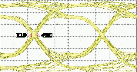
44 APPENDIX: SIGNAL INTEGRITY EYE DIAGRAMS SERIES RF00/RF0 Normally Closed Normally Open +0 mv +0 mv -0 mv -0 mv 0 ps 0 ps 0 ps 0 ps 0 ps 0 ps 0 ps 0 ps 0 ps 0 ps. mv 0. ps.. ps 0. mv. ps..00 ps SERIES SRF00/SRF0 Normally Closed Normally Open +0 mv +0 mv -0 mv -0 mv 0 ps 0 ps 0 ps 0 ps 0 ps 0 ps 0 ps 0 ps 0 ps 0 ps. mv. ps.. ps. mv. ps..00 ps SERIES GRF00/GRF0 Normally Closed Normally Open +0 mv +0 mv -0 mv -0 mv 0 ps 0 ps 0 ps 0 ps 0 ps 0 ps 0 ps 0 ps 0 ps 0 ps. mv 0.0 ps.. ps. mv. ps.. ps Page (00) (0) 0 TELEDYNE RELAYS
 RF PCB")
45 APPENDIX: SIGNAL INTEGRITY EYE DIAGRAMS SERIES SGRF00/SGRF0 Normally Closed Normally Open +0 mv +0 mv -0 mv -0 mv 0 ps 0 ps 0 ps 0 ps 0 ps 0 ps 0 ps 0 ps 0 ps 0 ps. mv.0 ps.. ps. mv 0. ps.. ps PATTERN GENERATOR SETTINGS 0 Gbps Random Pulse Pattern Generator - PRBS signal PRBS output of 00mV P-P (nominal) RF PCB effect (negligible) not removed from measurement Data shown is typical of both poles 0 TELEDYNE RELAYS SPECIFICATIONS SUBJECT TO CHANGE WITHOUT NOTICE Page

 -00 www.")
46 APPENDIX: SIGNAL INTEGRITY EYE DIAGRAMS SERIES RF00 Normally Closed Normally Open +0 mv +0 mv -0 mv -0 mv 0 ps 0 ps 0 ps 0 ps 0 ps 0 ps 0 ps 0 ps 0 ps 0 ps. mv. ps.0. ps. mv.0 ps.. ps SERIES GRF00 Normally Closed Normally Open +0 mv +0 mv -0 mv -0 mv 0 ps 0 ps 0 ps 0 ps 0 ps 0 ps 0 ps 0 ps 0 ps 0 ps. mv 0.0 ps.0. ps. mv. ps 0.. ps Page (00) (0) 0 TELEDYNE RELAYS


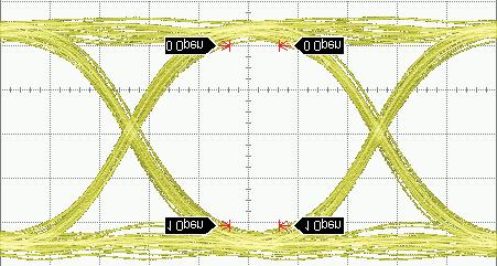
47 APPENDIX: SIGNAL INTEGRITY EYE DIAGRAMS SERIES SGRF00 Normally Closed Normally Open +0 mv +0 mv -0 mv -0 mv 0 ps 0 ps 0 ps 0 ps 0 ps 0 ps 0 ps 0 ps 0 ps 0 ps. mv.0 ps..00 ps. mv. ps.0. ps SERIES GRF Normally Closed Normally Open +0 mv +0 mv -0 mv -0 mv 0 ps 0 ps 0 ps 0 ps 0 ps 0 ps 0 ps 0 ps 0 ps 0 ps. mv. ps.. ps. mv 0. ps.. SERIES RF/RF Normally Closed Normally Open +0 mv +0 mv -0 mv -0 mv 0 ps 0 ps 0 ps 0 ps 0 ps 0 ps 0 ps 0 ps 0 ps 0 ps. mv. ps.. ps. mv.0 ps..00 ps 0 TELEDYNE RELAYS SPECIFICATIONS SUBJECT TO CHANGE WITHOUT NOTICE Page


 www.teledyne-europe.")
48 APPENDIX: SIGNAL INTEGRITY EYE DIAGRAMS SERIES GRF/GRF Normally Closed Normally Open +0 mv +0 mv -0 mv -0 mv 0 ps 0 ps 0 ps 0 ps 0 ps 0 ps 0 ps 0 ps 0 ps 0 ps 0.0 mv. ps.. ps. mv 0. ps 0.. ps SERIES RF Normally Closed Normally Open +0 mv +0 mv -0 mv -0 mv 0 ps 0 ps 0 ps 0 ps 0 ps 0 ps 0 ps 0 ps 0 ps 0 ps 0. mv. ps.. ps. mv. ps.. ps SERIES GRF Normally Closed Normally Open +0 mv +0 mv -0 mv -0 mv 0 ps 0 ps 0 ps 0 ps 0 ps 0 ps 0 ps 0 ps 0 ps 0 ps. mv.0 ps.. ps. mv. ps..00 ps Page (00) (0) 0 TELEDYNE RELAYS


49 APPENDIX: SIGNAL INTEGRITY EYE DIAGRAMS SERIES GRF Normally Closed Normally Open +0 mv +0 mv -0 mv -0 mv 0 ps 0 ps 0 ps 0 ps 0 ps 0 ps 0 ps 0 ps 0 ps 0 ps. mv 0. ps.. ps. mv. ps.. ps SERIES RF0 Normally Closed Normally Open +0 mv +0 mv -0 mv -0 mv 0 ps 0 ps 0 ps 0 ps 0 ps 0 ps 0 ps 0 ps 0 ps 0 ps 0. mv. ps. 0. ps. mv. ps. 0. ps SERIES GRF0 Normally Closed Normally Open +0 mv +0 mv -0 mv -0 mv 0 ps 0 ps 0 ps 0 ps 0 ps 0 ps 0 ps 0 ps 0 ps 0 ps. mv.0 ps.. ps 0. mv.0 ps. 0. ps 0 TELEDYNE RELAYS SPECIFICATIONS SUBJECT TO CHANGE WITHOUT NOTICE Page
 -00 www.teledynerelays.com + (0) www.teledyne-europe.")
50 APPENDIX: SIGNAL INTEGRITY EYE DIAGRAMS SERIES RF Typical Path +0 mv -0 mv 0 ps 0 ps 0 ps 0 ps 0 ps.0 mv 0. ps.. ps SERIES GRF Normally Closed +0 mv -0 mv 0 ps 0 ps 0 ps 0 ps 0 ps.0 mv 0. ps.. ps SERIES SGRF Normally Closed +0 mv -0 mv 0 ps 0 ps 0 ps 0 ps 0 ps.0 mv 0. ps.. ps Page (00) (0) 0 TELEDYNE RELAYS


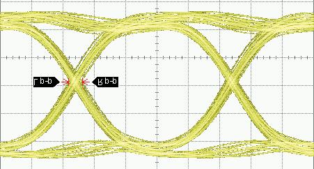
51 APPENDIX: SIGNAL INTEGRITY EYE DIAGRAMS SERIES RF0/RF Normally Closed Normally Open +0 mv +0 mv -0 mv -0 mv 0 ps 0 ps 0 ps 0 ps 0 ps 0 ps 0 ps 0 ps 0 ps 0 ps. mv. ps.. ps. mv 0. ps.. ps SERIES RF0/RF Normally Closed Normally Open +0 mv +0 mv -0 mv -0 mv 0 ps 0 ps 0 ps 0 ps 0 ps 0 ps 0 ps 0 ps 0 ps 0 ps. mv. ps.. ps. mv 0. ps.. ps SERIES A0 Attenuated Path Thru Path +0 mv +0 mv -0 mv -0 mv 0 ps 0 ps 0 ps 0 ps 0 ps 0 ps 0 ps 0 ps 0 ps 0 ps. mv. ps.0.00 ps 0. mv. ps. 0. ps 0 TELEDYNE RELAYS SPECIFICATIONS SUBJECT TO CHANGE WITHOUT NOTICE Page


 RF PCB effect (negligible) not removed from")
 www.teledyne-europe.")
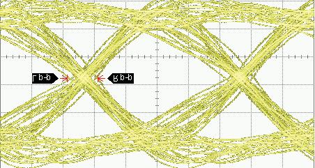
52 APPENDIX: SIGNAL INTEGRITY EYE DIAGRAMS SERIES GA0 Attenuated Path Thru Path +0 mv +0 mv -0 mv -0 mv 0 ps 0 ps 0 ps 0 ps 0 ps 0 ps 0 ps 0 ps 0 ps 0 ps.0 mv. ps.. ps 0. mv. ps.0. ps SERIES A Attenuated Path Thru Path +0 mv +0 mv -0 mv -0 mv 0 ps 0 ps 0 ps 0 ps 0 ps 0 ps 0 ps 0 ps 0 ps 0 ps.0 mv. ps.. ps. mv.0 ps.. ps SERIES GA Attenuated Path Thru Path +0 mv +0 mv -0 mv -0 mv 0 ps 0 ps 0 ps 0 ps 0 ps 0 ps 0 ps 0 ps 0 ps 0 ps. mv.0 ps.. ps. mv. ps.0. ps PATTERN GENERATOR SETTINGS 0 Gbps Random Pulse Pattern Generator - PRBS signal PRBS output of 00mV P-P (nominal) RF PCB effect (negligible) not removed from measurement Data shown is typical of both poles Page 0 (00) (0) 0 TELEDYNE RELAYS
53 RoHS and REACH CERTIFICATE OF COMPLIANCE RoHS It is hereby stated and certifi ed that Teledyne Relays complies with the Restrictions on Hazardous Substances (RoHS) Directives to the extent herein: Teledyne Relays does not use any of the Restricted Substances specifi ed by the RoHS Directives (listed below) as components in TO- and Centigrid Electromechanical Relay products, nor are these substances employed during any electromechanical relay manufacturing process: Lead Mercury Cadmium Hexavalent Chromium Polybrominated Biphenyls (PBB s) Polybrominated Diphenyl Ethers (PBDE s) However, upon request from the Customer, relay leads may be coated with solder, which contains 0% tin and 0% lead. REACH It is hereby stated and certifi ed that Teledyne Relays complies with the Registration Evaluation Authorization and Restriction of Chemicals (REACH) Directives to the extent stated herein: Teledyne Relays is a manufacturer of articles. Teledyne Relays has taken the initiative to review the () substances that are under consideration for treatment as Substances of Very High Concern (SVHC) candidates. Teledyne Relays confirmed that our relays do not contain any of the listed substances in concentration >0.% weight per supplied article, substance or preparation weight. For Additional Information please us at: relays@teledyne.com 0 TELEDYNE RELAYS SPECIFICATIONS SUBJECT TO CHANGE WITHOUT NOTICE Page
54 APPENDIX: TELEDYNE RELAYS PART NUMBERING SYSTEM LoopBack Relays Relay Series LB YZ Ground Pin (Optional) Y = Center Position Z = Center Position Blank = No ground pin Relay Series GLB= Stub Pins SGLB = SMT J-Leads Ground Pin (Optional) Y = Center Position Z = Center Position Blank = No ground pin SGLB YZ Coil Voltage = V = V Capacitance 00= 00nF 00 = 0nF Coil Voltage = V = V Capacitance 00= 00nF 00 = 0nF Relay Series Ground Pin Option (See Appendix) * Not Applicable for GRF Relays RF Relays (Except Attenuator Relays) RF00 X - / S Q Q = Solder-Coated Leads G = Gold-Plated Leads (RoHS Compliant) R = RoHS Compliant Solder * Lead finsih Sn0/Pb0 standard for J-Lead Relays S = 0. Leads No Suffix = 0. Leads Nominal Coil Voltage ( =. V) T R Established Reliability Relays Established Reliability Designator Relay Series Ground Pin Option (See Appendix) Pad Option (See Appendix) Nominal Coil Voltage ( =. V) ER Y M - A / S Q Q = Solder-Coated Leads G = Gold-Plated Leads (RoHS Compliant) R = RoHS Compliant Solder S = 0. Leads W =. Leads No Suffix = 0. Leads Screening and Reliability Level (See Appendix for Screening Options) General Note: Parts ordered without suffix may be supplied with Solder-Coated or Gold-Plated leads Parts ordered with Solder-Coated leads will have (Sn0/Pb0) Parts ordered with RoHS Solder-Coated leads will have (Sn./Cu0.) Not Applicable to GRF relays SMT=Surface Mount Technology Page (00) (0) 0 TELEDYNE RELAYS
55 APPENDIX: TELEDYNE RELAYS PART NUMBERING SYSTEM Military Qualified (JAN) Relays Military (JAN) Designator Relay Series Ground Pin Option (See Appendix) Pad Option (See Appendix) J Z M - P L Screening and Reliability Level (See Appendix for Screening Options) P = 0. Leads W =. Leads No Suffix = 0. Leads Nominal Coil Voltage ( =. V) Relay Series Commercial Surface Mount Relays S - / R Q = Solder-Coated Leads (Surface Mount Relays are Solder-Coated by default) R = RoHS Compliant Solder Nominal Coil Voltage ( =. V) Commercial Relays, (Except Surface Mount Relays) Y M - / S Q Relay Series Ground Pin Option (See Appendix) Pad Option (See Appendix) Q = Solder-Coated Leads G = Gold-Plated Leads (RoHS Compliant) R = RoHS Compliant Solder S = 0. Leads No Suffix = 0. Leads Nominal Coil Voltage ( =. V) High Performance Relays DV X M - / S G Relay Series Q = Solder-Coated Leads Ground Pin Option (See Appendix) Pad Option (See Appendix) G = Gold-Plated Leads (RoHS Compliant) R = RoHS Compliant Solder S = 0. Leads W =. Leads No Suffix = 0. Leads Nominal Coil Voltage ( =. V) General Note: Parts ordered without suffix may be supplied with Solder-Coated or Gold-Plated leads. Parts ordered with Solder-Coated leads will have (Sn0/Pb0) Parts ordered with RoHS Solder-Coated leads will have (Sn./Cu0.) 0 TELEDYNE RELAYS SPECIFICATIONS SUBJECT TO CHANGE WITHOUT NOTICE Page
56 TO- Package Relays (Through Hole) APPENDIX: TELEDYNE RELAYS DIMENSIONS CASE DETAIL.0 (.0) DIA. MAX.. (.) DIA. MAX. H. (.) MAX..0 (.) ±.00 (0.) WIRE LEAD:. (.0) MIN. TERMINAL LOCATIONS AND PIN NUMBERING (REF. ONLY) (Viewed from Terminals).00 (.0) ±.00 (.) DIA..0 (.) ±.00 (0.0) TRANSISTOR BASE CONNECTION FOR TRANSISTOR TN ONLY OPTION ± TYP (.0).0 (.).00 (.0) DIA. H Dimension Max inches (mm) Applicable Relay Series: 0.0 (.), D, DD, T 0. (.), D, TN, RF00, RF00D, RF00DD, RF0, RF0, RF (.), D, RF, 0, 0D, 0DD,, D, DD,, D, DD 0. (.) RF, SI00, RF, RFD 0. (.), D, DD, T 0. (.), D, TN, RF0, RF0D, RF0DD, RF, RF 0.00 (0.) RF, SI0 Page (00) (0) 0 TELEDYNE RELAYS
57 TO- Package Relays (Through Hole) APPENDIX: TELEDYNE RELAYS DIMENSIONS.0 (.0) DIA. MAX.. (.) DIA. MAX. H.0 (.) MAX. WIRE LEAD:. (.0) MIN. PIN:. (.) ±.00 (.) (See Note ) TERMINAL LOCATIONS AND PIN NUMBERING (REF. ONLY) (Viewed from Terminals).0 (.) ±.00 (0.0).0 (.) ±.00 (0.).00 (.0) ±.00 (.) DIA. ± TYP (.0).0 (.).00 (.0) DIA. DIMENSIONS ARE SHOWN IN INCHES (MILLIMETERS) H Dimension Max inches (mm) Applicable Relays: 0.0 (.) RF, ER, ERD, ERDD, J, JD, JDD CASE DETAIL.0 (.0) DIA. MAX.. (.) DIA. MAX..0(.) ±.00(0.0).00(.0) ±.00(.) DIA. H. (.) MAX..0 (.) ±.00 (0.) +.00 (.0).0 (.) ±.00 (.0) DIA. WIRE LEAD:. (.0) MIN. PIN:. (.) ±. 00 (.) (See Note ) ± TYP. LEADS ± TYP. T,, D, D, DD DD T T, D, DD RF RF LEADS H Dimension Max inches (mm) 0.0 (.), D, DD, T 0. (.) RF 0. (.), D, DD, T 0. (.) RF Applicable Relays: 0 TELEDYNE RELAYS SPECIFICATIONS SUBJECT TO CHANGE WITHOUT NOTICE Page
58 TO- Package Relays (Surface Mount) APPENDIX: TELEDYNE RELAYS DIMENSIONS. MAX (.).0 (.) REF.0 (.) REF. MAX () H (GRF00). MAX (0.) (GRF0). MAX (.) LEADS.0 REF (.).00±0.0 ±.00 (.0 (. ± ±0.) DIA. ± TYP H Dimension Max inches (mm) 0. (.00) GRF (.) GRF 0. (.) GRF, GRF, GRFD 0. (0.0) GRF0 0.0 (.) GRF Applicable Relays: H. [] MAX.0 [0.] REF.0 [0.] REF Ø.0 [.] MAX Ø.00 [Ø.0] ± TYP H Dimension Max inches (mm) 0. (.00) GRF Applicable Relays: Page (00) (0) 0 TELEDYNE RELAYS
59 APPENDIX: TELEDYNE RELAYS DIMENSIONS TO- Package Relays (J-Lead Surface Mount) Ø. MAX (.).0 REF (0.).0 REF (0.) SGRF00.0 HMAX (.).0 MAX (.) SGRF0.0 MAX (.).0 REF (.) () LEADS Ø ( ) X ( ) Ø.00 ±.00 (.0 ±0.) ± TYP H Dimension Max inches (mm) 0.0 (.) SGRF (.) SGRF, SGRF, SGRFD 0.0 (.) SGRF0 0. (.) SGRF Applicable Relays: H H Dimension Max inches (mm) 0.0 (.) SRF00 0. (.) S, SD, SDD 0.0 (.) SRF0 Applicable Relays: 0 TELEDYNE RELAYS SPECIFICATIONS SUBJECT TO CHANGE WITHOUT NOTICE Page
60 APPENDIX: TELEDYNE RELAYS DIMENSIONS Centigrid Package Relays (Through Hole). (.) SQ. MAX.. (.) SQ. MAX..0 ±.00 (. ±.0).0 ±.00 (. ±.). (.) MAX. H.00 ±.00 (. ±.) TYP PLACES WIRE LEAD.0 (.0) MIN. PIN:. (.).00 (.) PIN:. (.) ±.00 (.) (See Notes and ) +.00 (.0).0 (.) DIA..00 (.0) H Dimension Max inches (mm) Applicable Relay Series: 0. (.), D, DD 0.0 (.), D 0.0 (.) RF00 0. (.), D, DD 0. (0.0) RF0 Centigrid Package Relays (Surface Mount). SQ (.) MAX.0 REF (0.).0 REF (0.).0 MAX (.) H.0 REF (0.).00 TYP (.). SQ (.) MAX LEADS LENGTH DIA..0 (0.) REF (0.) TYP (.) H Dimension Max inches (mm) Applicable Relay Series: 0.0 (.) GRF00, GRF, GRFD 0. (.0) GRF0 Page (00) (0) 0 TELEDYNE RELAYS
61 APPENDIX: TELEDYNE RELAYS DIMENSIONS Centigrid Package Relays (J-Lead Surface Mount). SQ MAX (.).0 REF (0.).0 REF (0.) SRGF00. HMAX (.0) SRGF0.0.0 REF MAX (.) (.) +.00 X ( ).00 ±0.00 TYP (. ±0.). SQ MAX (.) () LEADS +.00 Ø (0. 0.0).00 ±0.00 TYP (. ±0.) H Dimension Max inches (mm) Applicable Relay Series: 0. (.0) SGRF (.) SGRF0. MAX (.).0 REF (.).0 REF (.) MAX TYP MAX TYP.0 MIN PL (.).00 PL (.). MAX (.).0 MAX (.) H.00 TYP (.). SQ MAX (.).00 (.0).0 MIN (0.) TYP ( ) Ø.0 REF (.) ± TYP.00 (.0) (Note ).00 (.0) H Dimension Max inches (mm) Applicable Relay Series: 0.0 (.) S, SD, SDD 0.0 (.0) S, SD 0.0 (.) S, SD, SDD 0 TELEDYNE RELAYS SPECIFICATIONS SUBJECT TO CHANGE WITHOUT NOTICE Page
62 APPENDIX: TELEDYNE RELAYS DIMENSIONS Extended Centigrid Package Relays (RF - Through Hole) H H Dimension Max inches (mm) Applicable Relay Series: 0. (.) RF Extended Centigrid Package Relays (GRF - Surface Mount) H H Dimension Max inches (mm) Applicable Relay Series: 0. (.) GRF Page 0 (00) (0) 0 TELEDYNE RELAYS
63 APPENDIX: TELEDYNE RELAYS DIMENSIONS Extended Centigrid Package Relays (Through Hole). MAX. (.). MAX. (.0). MAX. (.).0 REF. (0.).0 REF. (0.) 0 H.00 MAX. (.).00 (.) TYP.. MAX. (.0). MIN. (.0) (0.) + (0.0) (0.0) 0 LEADS DIA. PIN NUMBERS FOR REF. ONLY.00 (.0) H Dimension Max inches (mm) Applicable Relay Series: 0. (.) C 0.00 (.) RF0. MAX. (.). MAX. (.0).0 ±.00 (. ±.0). MAX. (.).0 ±.00 (. ±.). MAX. (.). MIN. (.0).00 ±.00 (. ±.) TYP 0. MAX. (.0) +.00 (.0).0 (.) DIA. ±.00 (.0) LEADS.00 ±.00 (.0 ±0.) H Dimension Max inches (mm) Applicable Relay Series: 0. (.) C 0. (.) C 0 TELEDYNE RELAYS SPECIFICATIONS SUBJECT TO CHANGE WITHOUT NOTICE Page
64 APPENDIX: TELEDYNE RELAYS DIMENSIONS Extended Centigrid Package Relays (Through Hole). MAX. (.). MAX. (.0). MAX. (.).00 ±.0 (.0 ±.0) DIA..00 ( ).0 (.) H.00 MIN. (.).0 REF. (.).0 ±.0 TYP. (. ±.).0 REF. (.). MAX. (.0) H Dimension Max inches (mm) Applicable Relay Series: 0.0 (.) A0 0. (.) A Extended Centigrid Package Relays (Surface Mount) H. MAX [. ]. MAX [.0 ] H Dimension Max inches (mm) Applicable Relay Series: 0. (.) GA Page (00) (0) 0 TELEDYNE RELAYS
65 APPENDIX: TELEDYNE RELAYS DIMENSIONS LoopBack Package Relays (Through Hole) (Optional) H (Optional) H Dimension Max inches (mm) Applicable Relay Series: 0. (.) LB LoopBack Package Relays (Surface Mount) H RF GROUND SHIELD (SEE NOTE.) H Dimension Max inches (mm) Applicable Relay Series: 0. (0.) GLB 0 TELEDYNE RELAYS SPECIFICATIONS SUBJECT TO CHANGE WITHOUT NOTICE Page
66 APPENDIX: TELEDYNE RELAYS DIMENSIONS LoopBack Package Relays (J-Lead Surface Mount) H RF GROUND SHIELD (SEE NOTE ) H Dimension Max inches (mm) Applicable Relay Series: 0. (.) SGLB Half-Size Crystal Can Package Relays (Through Hole).0 MAX (0.).0 MAX (0.) CONTRASTING GLASS (X). MAX (0.) X.00 (.) H.0 MAX (0.).00 TYP (.0). MAX (0.) LEADS. ±.00 (. ±0.) MEASUREMENTS IN INCHES (MILLIMETERS).00 TYP (.0) X.00 (.) H Dimension Max inches (mm) Applicable Relay Series: 0.0 (0.),, RF, RF Page (00) (0) 0 TELEDYNE RELAYS
67 Handling Guidelines for TO- and Centigrid Relays ) Do not drop, throw or in any way mishandle individual relays, cartons containing relay packs, or individual relay packs. ) Store unused relays in a humidity controlled, shock and vibration-free environment. Storage temperature range limits -ºC to + ºC, however, when possible, relays should be stored in a ºC environment. ) Observe normal good practice in the handling and storage of any relay packs marked as static sensitive. ) When removing relays from packaging, do so with care. If removing relays from Styrofoam packaging, remove relays carefully as pouring them from the packaging may cause damage to the relay. If removing from bulk packaging, gently pour the relays from the container, taking care to not allow the relays to drop from the container onto the new surface, to prevent unnecessary shock. Do not allow relays to fall onto the fl oor. ) When transferring relays to the production area after unpacking, do not drop, throw, or mishandle the relays in any way. When removing relays from the container, pouring is acceptable but again should be done gently and in a way as to not allow the relays to drop. ) Attached relay spreader pads and insulating pads should not be removed from the relays. ) Relays should not be exposed to any process or environment that exceeds any limits within this guide or any published specifi cation that applies to the relay. ) Relays are hermetically sealed. Damaged to the casing or glass-to-metal seals will compromise the relays performance and reliability. ) Never subject relays to ultrasonic cleaning environments. 0) Unless otherwise specifi ed, do not subject relays to solder refl ow temperatures above 0ºC, minute maximum. ) Do not stack heavy object directly onto relays. ) Excessive handling of relay leads with bare hands, or exposure of the relay leads with other contaminating sources can compromise their solderability. ) Avoid exceeding -pound pull strength of the terminals. ) Avoid subjecting magnetic latching relays to large magnetic fi elds. Do not handle magnetic latching relays with magnetic holding tools. ) Avoid bending the fl ange, the base of the relays or bending/forming the leads in a manner which may result in deformation of the fl ange or base of the relays. Any such deformation, or handling, which results in visible deformations or dents to any part of the relays (including the cover) may compromise the precisely assembled internal parts of the relays, causing degradation of performance or potential permanent damage and may void the warranty. 0 TELEDYNE RELAYS SPECIFICATIONS SUBJECT TO CHANGE WITHOUT NOTICE Page
68 APPENDIX: Spacer Pads Pad designation and bottom view dimensions Height For use with the following: Dim. H Max. ER, ERD, ERDD. (.) Ø.0 [.] (REF), D, TN, RF00, RF0, RF0 RF00, RF0.00 (.) Dim H MAX ER0, ER0D, ER0DD,, ERD, ERDD, ER, ERD, ERDD,, D, RF.0 (.) ERT, ERT, ER, ERD, ERDD.00 (0.), D, TN, RF0, RF, RF.0 (0.) M Pad for TO- RF, RF SI00, SI0.0 (.) ER, ERD, ERDD, ERT. (.) Dim H MAX ER, ERD, ERDD.00 (0.) RF.00 (.) M Pad for TO- RF.0 (0.), D.0 (.) Dim H MAX ER, ERD, ERDD, J, JD, JDD.00 (.) ER, ERD, ERDD, J, JD, JDD.00 (0.) RF00. (.00) M Pad for Centigrid. [.] (REF) RF0.0 (0.) C, A.0 (.) Dim H MAX ERC, JC.00 (.). [.] (REF) ERC, JC.00 (0.) RF0. (.) M Pad for Centigrid Notes:. Spacer pad material: Polyester fi lm.. To specify an M or M spacer pad, refer to the mounting variants portion of the part numbering example in the applicable datasheet.. Dimensions are in inches (mm).. Unless otherwise specifi ed, tolerance is ±.00 (. mm).. Add 0 mω to the contact resistance shown in the datasheet.. Add 0.0 oz. (0. g) to the weight of the relay assembly shown in the datasheet. A0.0 (.) Page (00) (0) 0 TELEDYNE RELAYS
69 APPENDIX: Spreader Pads Pad designation and bottom view dimensions Height For use with the following: Dim. H Max..00 [.].0 [.].0 [.] MAX SQ.00 [.0] M Pad / /.00 [.].00 [.] Dim H MAX.0 [.] MIN.0 [0.] (REF) ERT, JT, ER, ERD ERDD, J, JD, JDD. (.) ERT, JT, D, TN. (.) ERT, JT, ER, ERD ERDD, J, JD, JDD. (.) ERT, JT, D, TN.0 (.) ER0, J0, ER0D, J0D ER0DD, J0DD, ER, J ERD, JD, ERDD JD, ERDD, JDD,. (0.).0 [.] SQ.00 [.] ERT ER, ERD, ERDD J, JD, JDD. (.0).00 [.].00 [.].0 [.] Dim H MAX, D. (.) ER, ERD, ERDD, D. (.).00 [.].0 [.].00 [.] M Pad / /.0 [.] MAX SQ.00 [.0] M Pad / / /.0 [.].00 [.].00 [.].0 [.] Dim H MAX.0 [.] MIN ERT ER, ERD, ERDD. (.), D. (.) ER, ERD, ERDD, ERTX ERX, ERDX, ERDDX ERTX. (.) X, DX, TNX. (.) ER0X, ER0DX, ER0DDX ERX, ERDX, ERDDX. (0.) ERX, ERDX ERDDX, X, DDX ER, ERD, ERDD ERTX ERX, ERDX, ERDDX ERTX. (.) X, DX, TNX.0 (.) Notes:. Spreader pad material: Diallyl Phthalate.. To specify an M, M or M spreader pad, refer to the mounting variants portion of the part number example in the applicable datasheet.. Dimensions are in inches (mm).. Unless otherwise specifi ed, tolerance is ±.00 (0. mm). /. Add mω to the contact resistance shown in the datasheet. /. Add.0 oz. (0. g) to the weight of the relay assembly shown in the datasheet. /. Add 0 mω to the contact resistance shown in the datasheet. /. Add 0.0 oz (0. g) to the weight of the relay assembly shown in the datasheet. /. M pad to be used only when the relay has a center pin (e.g. ERM-A, XM-.).0 [0.] (REF) 0 TELEDYNE RELAYS SPECIFICATIONS SUBJECT TO CHANGE WITHOUT NOTICE Page
70 APPENDIX: Ground Pin Positions Ø.00 [Ø.0] "Z" POSITION "X" POSITION "Z" POSITION Ø.00 [Ø.0] ± "Y" POSITION ± "Y" POSITION TO- Relays: ERT, ER, ERT, ER0, ER, ER, ERT, ER, ERT,, TN, 00H, 00K, 00V, RF00, RF0, RF, RF, RF, RF0, RF, RF0, RF, SI00, SI0, RF00, RF0 TO- Relays: ER, ER, RF, RF.00 [.] "Y" POSITION "W" POSITION.00 [.] "Y" POSITION "Z" POSITION.00 [.] "Z" POSITION.00 [.].00 [.] "X" POSITION.00 [.].00 [.] "U" POSITION (ERC and ERC only) Centigrid Relays: RF0, ERC, C, ERC Centigrid Relays: RF00, RF0, ER, ER, Z Position Loopback Relays: LB Y Position Indicates ground pin position Indicates glass insulated lead position Indicates ground pin or lead position depending on relay type NOTES. Terminal views shown. Dimensions are in inches (mm). Tolerances: ±.00 (±.) unless otherwise specifi ed. Ground pin positions are within.0 (0.) dia. of true position. Ground pin head dia., 0.0 (0.) ref: height 0.00 (0.) ref.. Lead dia. 0.0 (0.) nom. Page (00) (0) 0 TELEDYNE RELAYS


71 APPENDIX: Teledyne Relays T R Program Teledyne Relays program was developed to provide the JAN relay user an alternate means of specifying and procuring established reliability relays. The form, fit and function of a relay is the same as that of its JAN counterpart. program requirements differ in certain regimens/tests found in both MIL-PRF- and MIL-PRF-0 that add cost but no value to the relay. This program parallels the military specifi cations in most aspects. The components that make up such a program are intricate and varied. Furthermore, there are additional options of high value for design, manufacturability and operation of high reliability assemblies. The following page presents a table that compares the 00% screening performed on JAN relays and relays prior to shipment. Other signifi cant highlights of the program include: Two unique screening levels The ability to define lead finish Spacer pad options which may not be available in military specifi cations Ground pin options which may not be available in military specifi cations Reduced lead time Reduced cost The program is fully defined for both general product requirements and detailed product requirements in the following Teledyne Relays specifi cations: TR-R- TR-STD- TR-STD- TR-ERL- TR-R-/XXX TR Supplement Copies of these documents are available from Teledyne Relays. We suggest that users check with Teledyne Relays from time to time to assure that they have the latest issue. Can t Find What You Need? Check out our full line of relays and switches. Order literature online at 0 TELEDYNE RELAYS SPECIFICATIONS SUBJECT TO CHANGE WITHOUT NOTICE Page
72 APPENDIX: Teledyne Relays T R Program INSPECTION A Level.%/0K Cycles Screening Levels B Level.%/0K Cycles JAN L Level %/0K Cycles JAN M Level %/0K Cycles Subgroup Screening, Internal Moisture AQL Vibration (Sinusoidal) AQL Vibration (Sinusoidal) 00% Screening, Burn-In (Hybrids only) Screening, Run-In (Room Temperature) Screening, Run-In (+ C and C) Subgroup Coil Resistance or Coil Current Insulation Resistance Dielectric Withstanding Voltage Static Contact Resistance Pickup and Dropout or Set and Reset Voltage Operate and Release or Set and Reset Time Hold Voltage Turn-On and Turn-Off Time (Hybrids only) Contact Bounce Time Contact Stabilization Time Turn-On Current (T Hybrids only) Turn-On Voltage (C Hybrids only) Turn-Off Voltage (Hybrids only) Coil Transient Suppression (D, DD and Hybrids only) Diode Blocking Integrity (DD only) Zener Voltage (C Hybrid only) Neutral Screen (Latching Relays only) Break Before Make Verifi cation Contact Simultaneity Subgroup Solderability Samples per Daily Solderability Inspection Lot Leak Test External Visual and Mechanical Inspection /Lot for Dimension and Weight Check AQL = Acceptable Quality Level Page 0 (00) (0) 0 TELEDYNE RELAYS

73 Teledyne Relays HI-REL Program Teledyne Relays: Because in deep space there is no acceptable failure rate Teledyne Relays has a long history of supplying High Reliability relays for use in space bound vehicles. From the earliest deep space probes, such as Voyager I, now nearing billion miles out in space, to the next generation of probes scheduled for the future, Teledyne Relays continues to be the preeminent supplier of Hi-Reliability relays to the space market. Teledyne Relays Hi-Reliability Specification: TR-HIREL- Eliminates the need for customers to develop and maintain specifi cations. Manufacturing and Quality Assurance requirements are fully defi ned and documented. Meets the general requirements of both ESA/ SCC and NASA/GSFC documents. Offers options for 00% Group A screening Offers options for levels of Lot Acceptance Testing (LAT). Teledyne Screening Document 0-0- NASA approved screening regimen based on NASA/GSFC S--P. RELAY TYPES TO- Magnetic-Latching Relays TO- Non-Latching Relays TO- Magnetic-Latching, High-Shock Relays TO- Non-Latching, High-Shock Relays TO- Non-Latching, High-Vibration Relays HI-REL SCREENING CAPABILITIES 00% Open Electrical Inspection 00% Precap Inspection Fully Automated Small Particle Inspection (Millipore Clean) Asynchronous Miss Test Coil Continuity Sine Vibration Random Vibration High/Low Run In (Miss Test) C ± C Radiographic Inspection Mechanical Shock Test Thermal Shock Test Acceleration Radiographic Inspection (X-ray) Mechanical Shock Test Thermal Shock Test Acceleration Load Banks for a Variety of Life Test Load Serialized Printed Electrical Data Continuous Life Testing Environmental Testing Vertical Integration For information or answers to your questions, please visit our website. 0 TELEDYNE RELAYS SPECIFICATIONS SUBJECT TO CHANGE WITHOUT NOTICE Page


74 Did you know... Teledyne Relays offers electromechanical relays for various markets? RF RELAYS Signal Integrity up to 0Gbps DC - GHz Surface-Mount DPDT, SPDT, PST and Loopback Relays MILITARY GRADE RELAYS Built and tested to meet MIL-PRF-0 Built and tested to meet MIL-PRF- Built-in Diodes, Transistor Driver and CMOS Low Power coils TELEDYNE ESTABLISHED RELIABILITY RELAYS Fully defined product requirements and screening levels Spacer/Spreader pad options not allowed by military specifications Reduced lead time and cost vs Military Grade Gade HIGH PERFORMANCE RELAYS - C to +00 C Shock up to,000 g s Vibration up to 0 g s Non-Latching & Magnetic-Latching COMMERCIAL RELAYS Standard electrical tests at C Low cost switching solutions Surface-Mount Short lead times Page SPECIFICATIONS SUBJECT TO CHANGE WITHOUT NOTICE 0 Teledyne Relays Page (00) (0) 0 TELEDYNE RELAYS


 - www.")

75 Did you know... COAX SWITCHES Teledyne Coax Switches offers coaxial switches for ATE, Radar, Amplifier Switching, Etc.? SPDT SWITCHES DC - 0GHz, Internal 0 Ω Termination SMA, mini-smb, TNC & N Connectors Million Cycles High Power & Low PIM Failsafe & Latching TRANSFER SWITCHES DC - GHz SMA, TNC & N Connectors Million Cycles High Power Failsafe & Latching MULTI-THROW SWITCHES DC - 0 GHz, Internal 0 Ω Termination SMA, mini-smb, TNC & N Connectors SPT - SP0T Million Cycles Normally Open & Latching LOW PIM SWITCHES DC - GHz SMA, N and / D Connectors SPDT, Transfer and Multi-Throw Failsafe & Latching SPECIALTY SWITCHES DC - 0GHz -State Attenuated Switch Radiation Shielding Switch Blocks Redundant Diode Confi guration 0 Teledyne Coax Switches (00) (0) Page 0 TELEDYNE RELAYS SPECIFICATIONS SUBJECT TO CHANGE WITHOUT NOTICE Page


 www.")
76 Did you know... Teledyne Relays offers Commercial/Industrial Solid State Relays? SINGLE PHASE AC SOLID STATE RELAYS Up to 0Vac, A Input & Output Protection Chassis, DIN Rail and PCB Mount Zero-Cross & Random Switching Touch-Proof Covers DUAL-PHASE AC SOLID STATE RELAYS Up to 00Vac, 0A Output Protection Chassis and DIN Rail Zero-Cross & Random Switching Touch-Proof Covers & PHASE SOLID STATE RELAYS Up to 00Vac, A Output Protection Chassis and DIN Rail Zero-Cross & Random Switching DC & AC Control DC SOLID STATE RELAYS Up to 00Vdc, 00A Output Protection Chassis, DIN Rail and PCB Mount IGBT and MOSFET Touch-Proof Covers SOFT START MOTOR CONTROLLERS AND MOTOR REVERSERS Up to kw, 0Vac Star & Delta Confi gurations DIN Rail Output Protection Built-in Diagnostics and Self Test Page SPECIFICATIONS SUBJECT TO CHANGE WITHOUT NOTICE 0 Teledyne Relays Page (00) (0) 0 TELEDYNE RELAYS


77 Did you know... Teledyne Relays offers Military Solid State Relays? DC SOLID STATE RELAYS Meet MIL-PRF-0 Tested Per MIL-STD-0 Silicon Carbide MOSFET Up to 0Vdc, A Chassis and PCB Mount Short-Circuit Protection Plastic and Hermetically Sealed BI-DIRECTIONAL/AC SOLID STATE RELAYS Meet MIL-PRF-0 Tested Per MIL-STD-0 Up to 0Vac, A Chassis and PCB Mount Short-Circuit Protection Plastic and Hermetically Sealed COMMERCIAL, LOW POWER, I/O MODULES Up to 0Vac, 0A Short-Circuit Protection Chassis and PCB Mount Zero-Cross & Random Switching Low Off-State Leakage Current SILICON CARBIDE TECHNOLOGY Up to 0Vdc, 0 A Meet MIL-PRF-0 Tested Per MIL-STD-0 Low ON resistance Low Profile Hermetic Package 0 Teledyne Coax Switches (00) (0) Page 0 TELEDYNE RELAYS SPECIFICATIONS SUBJECT TO CHANGE WITHOUT NOTICE Page


78 Did you know... Teledyne Coax Switches offers coaxial switch matrices for ATE, Radar, Filter Switching, Airborne Surveillance Systems, Etc.? MINI MATRICES COAX SWITCHES Remote Control via USB and/or Ethernet GUI controllable Accepts ASCII code Available in,. and 0 GHz SPDT, Transfer and Multi-throw configurations MULTIPLEXOR/FANOUT SWITCH MATRICES Up to x0 Switch Matrix SMA, mini-smb, TNC & N Connectors Failsafe, Latching or Normally Open Confi gurations Switching Systems for 0 Ω & Ω applications MIMO/BLOCKING AND MIMO SINGLE CONNECTION SWITCH MATRICES Up to x0 Switch Matrix SMA, mini-smb, TNC & N Connectors RS-, TTL, USB, GPIB, TTL, Ethernet Control Million Cycles Failsafe & Latching CUSTOMIZED SWITCH MATRICES EMI/RFI Transient Suppression Ballistic Shock Fatigue Crash Load Altitude Page SPECIFICATIONS SUBJECT TO CHANGE WITHOUT NOTICE 0 Teledyne Relays Page (00) (0) 0 TELEDYNE RELAYS


 - www.")
79 Did you know... Teledyne Relays offers Space Qualified Switches? SPACE MARKET SEGMENTS SERVED Deep-Space Probes Manned Programs Communications Satellites Launch Vehicles Earth Observatory / Weather Satellites Commercial / Military Satellites CAPABILITIES Logistic Infrastructure Chemical Analysis Lab Scanning Electro Microscope In-house Plating Shop Enviroment Test Lab Field edtechnical ca Support ELECTROMECHANICAL RELAY SPECIFICATIONS MIL-PRF-0 MIL-PRF- NASA/GSFC S--P- NASA EEE-INST-00 ESA/SCC 0 & 0 0 Teledyne Coax Switches (00) (0) Page
Electromechanical Relays Selection Guide
 Electromechanical Relays Selection Guide Latching JAN Non-Latching RF Loopback Established Reliability PST Surface-Mount Environmental Attenuated Switching Solutions Teledyne Relays has been the world
Electromechanical Relays Selection Guide
 Electromechanical Relays Selection Guide Latching JAN Non-Latching RF Commercial Established Reliability Surface-Mount Attenuated Environmental Switching Solutions Teledyne Relays has been the world s
TO-5 RELAYS ESTABLISHED RELIABILITY MILITARY DPDT
 TO-5 RELAYS ESTABLISHED RELIABILITY MILITARY DPDT SERIES RELAY TYPE DPDT basic relay D DPDT relay with internal diode for coil transient suppression DD DPDT relay with polarity reversal protection and
CENTIGRID ESTABLISHED RELIABILITY RELAYS
 SERIES DESIGNATION CENTIGRID ESTABLISHED RELIABILITY RELAYS SENSITIVE DPDT 134 DPDT basic relay 134D 134DD RELAY TYPE DPDT relay with internal diode for coil transient suppression DPDT relay with internal
TO-5 RELAYS ESTABLISHED RELIABILITY MILITARY DPDT
 TO-5 RELAYS ESTABLISHED RELIABILITY MILITARY DPDT SERIES RELAY TYPE DPDT basic relay D DPDT relay with internal diode for coil transient suppression DD DPDT relay with polarity reversal protection and
MAGNETIC-LATCHING ESTABLISHED RELIABILITY TO-5 RELAYS
 MAGNETIC-LATCHING ESTABLISHED RELIABILITY TO-5 RELAYS SPDT SERIES 421 SERIES DESIGNATION RELAY TYPE 421 SPDT basic relay 421D 421DD SPDT relay with internal diode for coil transient suppression SPDT relay
MAGNETIC-LATCHING ESTABLISHED RELIABILITY TO-5 RELAYS DPDT RELAY TYPE. DPDT relay with internal diode for coil transient suppression
 ESTABLISHED RELIABILITY SERIES DESIGNATION MAGNETIC-LATCHING ESTABLISHED RELIABILITY TO-5 RELAYS DPDT 420/422 DPDT basic relay 420D/422D 420DD/422DD RELAY TYPE DPDT relay with internal diode for coil transient
LoopBack Relay. GLB363 Series. With Built-in AC Bypass Capacitors / DC LoopBack Relay
 GLB363 Series With Built-in AC Bypass Capacitors / DC SERIES DESIGNATION GLB363 RELAY TYPE, Sensitive Coil, Surface Mount Ground Shield and Stub pins with AC Bypass Capacitors or No capacitor DESCRIPTION
LoopBack Relay. LB363 Series. With Built-in AC Bypass Capacitors. LoopBack Relay, Sensitive Coil, thru-hole with AC Bypass Capacitors
 LB363 Series With Built-in AC Bypass Capacitors SERIES DESIGNATION LB363 RELAY TYPE, Sensitive Coil, thru-hole with AC Bypass Capacitors DESCRIPTION The LoopBack Series relay combines two DPDT electromechanical
SURFACE MOUNT HIGH REPEATABILITY, BROADBAND TO-5 RELAYS DPDT
 SURFACE MOUNT HIGH REPEATABILITY, BROADBAND TO-5 RELAYS DPDT SERIES GRF300 GRF300D GRF300DD GRF303 GRF303D GRF303DD RELAY TYPE Repeatable, RF relay Repeatable, RF relay with internal diode for coil transient
SURFACE MOUNT HIGH REPEATABILITY SPDT, BROADBAND 16 GHZ 40GBPS MAGNETIC-LATCHING RF RELAY
 SURFACE MOUNT HIGH REPEATABILITY SPDT, BROADBAND 16 GHZ 40GBPS MAGNETIC-LATCHING RF RELAY Series GRF121 SERIES GRF121 RELAY TYPE RF Magnetic-Latching, SPDT, Surface Mount Relay DESCRIPTION The ultraminiature
HIGH REPEATABILITY, DC-8 GHz/20Gbps TO-5 RELAYS, DPDT
 HIGH REPEATABILITY, DC-8 GHz/Gbps TO-5 RELAYS, DPDT SERIES RELAY TYPE RF3 RF33 Repeatable, RF relay Low Power Operating Coil, RF relay DESCRIPTION The ultra miniature RF3 is designed to improve upon the
MAGNETIC-LATCHING DC-8 GHz TO-5 RELAYS 4PST
 MagneticLatching Electromechanical Relay MAGNETICLATCHING DC8 GHz TO5 RELAYS PST SERIES SGRF SGRFD RELAY TYPE PST RF Relay PST RF Relay with internal diodes for coil transient suppression DESCRIPTION The
SURFACE MOUNT HIGH REPEATABILITY SPDT, BROADBAND 18 GHZ 40GBPS MAGNETIC-LATCHING RF RELAY
 SURFACE MOUNT HIGH REPEATABILITY SPDT, BROADBAND 18 GHZ 40GBPS MAGNETIC-LATCHING RF RELAY Series GRF121/GRF121R SERIES GRF121 GRF121R RELAY TYPE RF Magnetic-Latching, SPDT, Common Coil Negative, Surface
HIGH REPEATABILITY, TO-5 RELAYS DPDT
 HIGH REPEATABILITY, TO-5 RELAYS DPDT SERIES RELAY TYPE RF7 RF7 Repeatable, RF relay Sensitive, repeatable, RF relay DESCRIPTION The ultraminiature RF7 and RF7 relays are designed to provide improved RF
HIGH REPEATABILITY SPDT, BROADBAND 12 GHZ, 20 Gbps MAGNETIC-LATCHING RF RELAY
 HIGH REPEATABILITY SPDT, BROADBAND 12 GHZ, 20 Gbps MAGNETIC-LATCHING RF RELAY SERIES RF121 RF121R RELAY TYPE RF Magnetic-Latching, SPDT, Common Coil Negative, Through-Hole Relay RF Magnetic-Latching, SPDT,
SURFACE MOUNT HIGH REPEATABILITY, BROADBAND TO-5 RELAYS DPDT DC-4 GHz
 SURFACE MOUNT HIGH REPEATABILITY, BROADBAND TO-5 RELAYS DPDT DC-4 GHz SERIES RELAY TYPE GRF7 GRF73 Repeatable, RF relay Sensitive, repeatable, RF relay DESCRIPTION The ultraminiature GRF7 and GRF73 relays
MAGNETIC-LATCHING DPDT HALF-SIZE CRYSTAL CAN HIGH POWER RF RELAY DC-3 GHZ
 MAGNETIC-LATCHING DPDT HALF-SIZE CRYSTAL CAN HIGH POWER RF RELAY DC-3 GHZ SERIES RELAY TYPE Commercial, DPDT, High Power, Half-Size Crystal Can Relay Commercial, DPDT, High Power, Half-Size Crystal Can
Electromechanical Relays - Frequently Asked Questions
 Electromechanical Relays - Frequently Asked Questions Q: What is the contact carry rating? A: Our EMR are capable of hot switching 28W load plus 100 cycles of overload condition at 56W. Therefore at a
Series CCS-19 Multi-Throw DC-2 GHz Latching Coaxial Switch
 PART NUMBER CCS-19 CS-19 DESCRIPTION Commercial Latching Multi-throw, DC-2GHz, with N or TNC connectors Elite Latching Multi-throw, DC-2GHz, with N or TNC connectors The CCS-19/CS-19 is a broadband, multi-throw,
Series HD 2A, 60Vdc, True Output Status Feedback, Short-Circuit Protected DC Solid-State Relay
 Part* Number HD00CFW DESC Drawing Number HD00CFY 88062-008 HD02CFW HD02CFY 88062-006 HD20CFW HD20CFY 88062-004 HD22CFW HD22CFY 88062-002 HD24CFW HD24CFY Relay Description Solid State Relay (SSR) SSR with
Series CCP-32N Low PIM DC 3 GHz Latching SPDT Coaxial Switch
 COAX SWITCHES Series CCP-32N PART NUMBER CCP-32N DESCRIPTION Commercial Latching SPDT, DC-3GHz, Low PIM These switches are designed to have extremely low passive intermodulation for use in narrow bandwidth
RAMSES SERIES R 570 PART NUMBER SELECTION. SPDT up to 18 GHz. Our Most Important Connection is with You. N - TNC - BNC
 SPDT up to 18 GHz PART NUMBER SELECTION Frequency Range: 0: N up to 3 GHz 1: N up to 12.4 GHz 2: BNC up to 3 GHz 5: TNC up to 3 GHz 6: TNC up to 12.4 GHz D: TNC up to 18 GHz Type: 1: Failsafe 2: Failsafe
Series HR422/ HRS422 DC up to 1 GHz Magnetic Latching Space Grade DPDT Relay
 PART NUMBER HR422 DESCRIPTION Magnetic-Latching, DPDT, TO-5 Space Grade Relay (HIREL) HRS422 Magnetic-Latching, DPDT, TO-5 Space Grade Relay (HIREL), Surface Mount J-Leads Teledyne Relays HR/HRS422 Series
Series CD. 2A, 60Vdc Optically Isolated, Short-Circuit Protected DC Solid-State Relay ELECTRICAL SPECIFICATIONS
 2A, 60Vdc Optically Isolated, Short-Circuit Protected DC Solid-State Relay Part* DESC Drawing Relay Description Number Number CD00CFW Basic Solid-State Relay (SSR) CD00CFY 90091-008 CD01CFW SSR with Control
Series H-33S DC up to 26.5 GHz Latching SPDT Space Grade Coaxial Switch
 COAX SWITCHES Series H-33S PART NUMBER H-33S DESCRIPTION Space Grade Latching SPDT, Teledyne Coax Switches H-33S Series RF Coaxial Switch is a Commercial Off-The Shelf (COTS) product suitable for high
Series CCR-33K/CR-33 K Miniature DC 33.5 GHz Failsafe SPDT Coaxial Switch
 PART NUMBER CCR-33K CR-33K DESCRIPTION Commercial Failsafe SPDT, DC-33.5GHz Elite Failsafe SPDT, DC-33.5GHz The CCR-33K/CR-33K is a broadband, SPDT, electromechanical, coaxial switch designed to switch
Series CCR-39S/CR-39S Multi-Throw DC-18 GHz/DC-22 GHz Latching Coaxial Switch
 PART NUMBER CCR-39S CR-39S DESCRIPTION Commercial Latching Multi-throw, DC-8GHz Elite Latching Multi-throw, DC-22GHz The CCR-39S/CR-39S is a broadband, multi-throw, electromechanical coaxial switch designed
Series CCRS-33S/CRS-33S Miniature DC 18 GHz Failsafe 2P3T Coaxial Switch
 COAX SWITCHES Series CCRS-33S/CRS-33S PART NUMBER CCRS-33S CRS-33S DESCRIPTION Commercial Failsafe 2P3T, DC-18GHz Elite Failsafe 2P3T, DC-18GHz The CCRS-33S/CRS-33S is a broadband, 2P3T, electromechanical
Series HR412K/ HRS412K DC up to 1 GHz, High Shock Non-Latching Space Grade DPDT Relay
 Series HR412K/ HRS412K PART NUMBER HR412K HRS412K DESCRIPTION Non-Latching, DPDT, TO-5 Space Grade Relay (HIREL), High Shock Non-Latching, DPDT, TO-5 Space Grade Relay (HIREL), High Shock, Surface Mount
Series CCS-32/CS-32 High Power DC 12 GHz Failsafe SPDT Coaxial Switch
 PART NUMBER CCS-32 CS-32 DESCRIPTION Commercial Failsafe SPDT, DC-2GHz Elite Failsafe SPDT, DC-2GHz The CCS-32/CS-32 is a broadband, SPDT, electromechanical, coaxial switch designed to switch a microwave
Series CCRT-33S/CRT-33S Internal 50Ω Termination DC 18 GHz/DC-22 GHz Latching SPDT Coaxial Switch
 COAX SWITCHES Series CCRT-33S/CRT-33S PART NUMBER CCRT-33S CRT-33S DESCRIPTION Commercial Latching SPDT, DC-18GHz, Internal 50Ω Termination Elite Latching SPDT, DC-22GHz, Internal 50Ω Termination The CCRT-33S/CRT-33S
Series CCRT-33S/CRT-33S Internal 50Ω Termination DC 18 GHz/DC-22 GHz Failsafe SPDT Coaxial Switch
 COAX SWITCHES Series CCRT-33S/CRT-33S PART NUMBER CCRT-33S CRT-33S DESCRIPTION Commercial Failsafe SPDT, DC-18GHz, Internal 50Ω Termination Elite Failsafe SPDT, DC-22GHz, Internal 50Ω Termination The CCRT-33S/CRT-33S
AN-B21C-0004 Applications Note
 Rev. A, 10/12/09 SD 2009 Coto Technology All Rights Reserved 1/10 B21C Relay Specification Data TEST PARAMETERS CONDITIONS 1,2 MIN NOM MAX UNITS COIL SPECIFICATIONS COIL RESISTANCE 140.0 155.0 170.0 Ω
Series H-47N DC up to 12 GHz Latching Transfer Space Grade Coaxial Switch
 COAX SWITCHES Series H-47N PART NUMBER H-47N DESCRIPTION Space Grade Latching Transfer, DC up to 12GHz Teledyne Coax Switches H-47N Series RF Coaxial Switch is a Commercial Off-The Shelf (COTS) product
Series CCT-59S/CT-59S Multi-Throw DC-26.5 GHz Latching Coaxial Switch
 PART NUMBER CCT-59S CT-59S DESCRIPTION Commercial Latching Multi-throw, DC-26.5GHz Elite Latching Multi-throw, DC-26.5GHz The CCT-59S/CT-59S is an Internally Terminated broadband, multi-throw, electromechanical
Series HR422K/ HRS422K DC up to 1 GHz, High Shock Magnetic Latching Space Grade DPDT Relay
 PART NUMBER HR422K DESCRIPTION Magnetic-Latching, DPDT, TO-5 Space Grade Relay (HIREL), High Shock HRS422K Magnetic-Latching, DPDT, TO-5 Space Grade Relay (HIREL), High Shock, Surface Mount J-Leads Teledyne
Series CCS-37K/CS-37K Miniature DC 36 GHz Latching TRANSFER Coaxial Switch
 PART NUMBER CCS-37K CS-37K DESCRIPTION Commercial Latching TRANSFER, DC-36GHz Elite Latching TRANSFER, DC-36GHz The CCS-37K/CS-37K is a long-life high performance transfer switch designed for use in 50
Series CCR-40K/CR-40K Miniature DC 40 GHz Latching SPDT Coaxial Switch
 COAX SWITCHES Series CCR-40K/CR-40K PART NUMBER CCR-40K CR-40K DESCRIPTION Commercial Latching SPDT, DC-40GHz, 2.92mm. Elite Latching SPDT, DC-40GHz, 2.92mm. The CCR-40K/CR-40K is a broadband, SPDT, electromechanical,
Series CCR-33K/CR-33K Miniature DC 33.5 GHz Failsafe SPDT Coaxial Switch
 PART NUMBER CCR-33K CR-33K DESCRIPTION Commercial Failsafe SPDT, DC-33.5GHz Elite Failsafe SPDT, DC-33.5GHz The CCR-33K/CR-33K is a broadband, SPDT, electromechanical, coaxial switch designed to switch
Series CCT-59S Multi-Throw DC-18 GHz, SP7T & SP8T Latching Coaxial Switch, Internal 50Ω Termination
 COAX SWITCHES Series CCT-59S PART NUMBER CCT-59S DESCRIPTION Commercial Latching Multi-throw, DC-18GHz The CCT-59S is a broadband, multi-throw, electromechanical coaxial switch designed to switch a microwave
Series CCP-47N Low PIM DC 3 GHz Latching TRANSFER Coaxial Switch
 COAX SWITCHES Series CCP-47N PART NUMBER CCP-47N DESCRIPTION Commercial Latching TRANSFER, DC-3GHz, Low PIM These switches are designed to have extremely low passive intermodulation for use in narrow bandwidth
Series CCR-33S/CR-33S Miniature DC 18 GHz/DC-22 GHz Failsafe SPDT Coaxial Switch
 COAX SWITCHES Series CCR-33S/CR-33S PART NUMBER CCR-33S CR-33S DESCRIPTION Commercial Failsafe SPDT, DC-18GHz Elite Failsafe SPDT, DC-22GHz The CCR-33S/CR-33S is a broadband, SPDT, electromechanical, coaxial
Series CCRS-53S/CRS-53S Miniature DC 26.5 GHz Failsafe 2P3T Coaxial Switch
 COAX SWITCHES Series CCRS-53S/CRS-53S PART NUMBER CCRS-53S CRS-53S DESCRIPTION Commercial Failsafe 2P3T, DC-26.5GHz Elite Failsafe 2P3T, DC-26.5GHz The CCRS-53S/CRS-53S is a broadband, 2P3T, electromechanical
Series HR255/HR257 DC up to 3 GHz Magnetic Latching Space Grade DPDT Relay
 PART NUMBER HR255, HR257 DESCRIPTION Magnetic-Latching, DPDT, Half-Size Crystal Can, Space Grade Relay (HIREL) Teledyne Relays HR255/257 Series relay is a High Reliability Off-The Shelf (COTS) relay suitable
Series CCT-38S Multi-Throw DC 12 GHz, SP7T & SP8T Normally Open Coaxial Switch
 COAX SWITCHES Series CCT-38S PART NUMBER CCT-38S DESCRIPTION Commercial Normally Open Multi-throw, DC-12 GHz The CCT-38S is a broadband, multi-throw, electromechanical coaxial switch designed to switch
Series CCT-58S/CT-58S Multi-Throw DC-26.5 GHz Normally Open Coaxial Switch
 COAX SWITCHES Series CCT-58S/CT-58S PART NUMBER CCT-58S CT-58S DESCRIPTION Commercial Normally Open Multi-throw, DC-26.5GHz Elite Normally Open Multi-throw, DC-26.5GHz The CCT-58S/CT-58S is an internally
Application Note 1047
 Low On-Resistance Solid-State Relays for High-Reliability Applications Application Note 10 Introduction In military, aerospace, and commercial applications, the high performance, long lifetime, and immunity
Table of Contents. Kilovac Time Delay Relays
 Table of Contents 1600/1700 Series, Delay on Operate, Fixed & Adjustable......................8-2, 8-3 2400 Series, Subminiature, Delay on Operate, Fixed.............................8-4 5600/5700 Series,
Series CCT-58S/CT-58S Multi-Throw DC-26.5 GHz Normally Open Coaxial Switch
 COAX SWITCHES Series CCT-58S/CT-58S PART NUMBER CCT-58S CT-58S DESCRIPTION Commercial Normally Open Multi-throw, DC-26.5GHz Elite Normally Open Multi-throw, DC-26.5GHz The CCT-58S/CT-58S is an internally
Series CCT-38S/CT-38S Multi-Throw DC 18 GHz/DC-22 GHz Normally Open Coaxial Switch
 COAX SWITCHES Series CCT-38S/CT-38S PART NUMBER CCT-38S CT-38S DESCRIPTION Commercial Normally Open Multi-throw, DC-18GHz Elite Normally Open Multi-throw, DC-22GHz The CCT-38S/CT-38S is an internally terminated,
FMSW6097 DATA SHEET. SPDT Failsafe Electro-Mechanical Relay Switch From DC to 26.5 GHz, 20 Watts with TTL, Diodes, Indicators, SMA.
 SPDT Failsafe Electro-Mechanical Relay Switch From DC to 26.5 GHz, 20 Watts with TTL, Diodes, Indicators, SMA The FMSW6097 is an SPDT Electromechanical Relay Switch that operates over a wide frequency
FMSW6124 DATA SHEET. Transfer Latching Electro-Mechanical Relay Switch From DC to 40 GHz, 5 Watts with Indicators, TTL, Self Cut Off, Diodes, 2.
 Transfer Latching Electro-Mechanical Relay Switch From DC to 40 GHz, 5 Watts with Indicators, TTL, Self Cut Off, Diodes, 2.92mm The FMSW6124 is a Transfer Electromechanical Relay Switch that operates over
Series CCS-47/CS-47 High Power DC 12 GHz Latching TRANSFER Coaxial Switch
 PART NUMBER CCS-47 CS-47 DESCRIPTION Commercial Latching TRANSFER, DC-GHz Elite Latching TRANSFER, DC-GHz The CCS-47/CS-47 is a long-life high performance transfer switch designed for use in 5 Ohms coaxial
Series CCRS-53S/CRS-53S Miniature DC 26.5 GHz Latching 2P3T Coaxial Switch
 COAX SWITCHES Series CCRS-53S/CRS-53S PART NUMBER CCRS-53S CRS-53S DESCRIPTION Commercial Latching 2P3T, DC-26.5GHz Elite Latching 2P3T, DC-26.5GHz The CCRS-53S/CRS-53S is a broadband, 2P3T, electromechanical
CORRY MICRONICS, INC. 761 COMMONWEALTH DRIVE SUITE 201 WARRENDALE, PA P F
 CORRY MICRONICS, INC. 761 COMMONWEALTH DRIVE SUITE 201 WARRENDALE, PA 15086 P 724.940.7556 F 724.940.7707 EMAIL: SALES@CORMIC.COM WWW.CORMIC.COM Manufacturers of RF and Microwave Components and Assemblies
Series CCR-33K/CR-33K Miniature DC 33.5 GHz Latching SPDT Coaxial Switch
 COAX SWITCHES Series CCR-33K/CR-33K PART NUMBER CCR-33K CR-33K DESCRIPTION Commercial Latching SPDT, DC-33.5GHz Elite Latching SPDT, DC-33.5GHz The CCR-33K/CR-33K is a broadband, SPDT, electromechanical,
Series CCR-33S/CR-33S Miniature DC 18 GHz/DC-22 GHz Latching SPDT Coaxial Switch
 PART NUMBER CCR-33S CR-33S DESCRIPTION Commercial Latching SPDT, DC-18GHz Elite Latching SPDT, DC-22GHz The CCR-33S/CR-33S is a broadband, SPDT, electromechanical, coaxial switch designed to switch a microwave
Series CCRT-53S/CRT-53S Internal 50Ω Termination DC-26.5 GHz Failsafe SPDT Coaxial Switch
 COAX SWITCHES Series CCRT-53S/CRT-53S PART NUMBER CCRT-53S CRT-53S DESCRIPTION Commercial Failsafe SPDT, DC-26.5GHz, Internal 5Ω Termination Elite Failsafe SPDT, DC-26.5GHz, Internal 5Ω Termination The
Series CCR-48K/CR-48K Multi-Throw DC 40 GHz Normally Open Coaxial Switch
 COAX SWITCHES Series CCR-48K/CR-48K PART NUMBER CCR-48K CR-48K DESCRIPTION Commercial Normally Open Multi-throw, DC-40GHz Elite Normally Open Multi-throw, DC-40GHz The CCR-48K/CR-48K is a broadband, multi-throw,
Monolithic Amplifier CMA-103+ Ultra Linear Low Noise, Ceramic to 4 GHz
 Ultra Linear Low Noise, Ceramic Monolithic Amplifier 50Ω 0.05 to 4 GHz The Big Deal Ceramic, hermetically sealed, nitrogen filled Low profile case, 0.045 Ultra High IP3 Broadband High Dynamic Range CASE
Series CCS-47/CS-47 High Power DC 12 GHz Failsafe TRANSFER Coaxial Switch
 COAX SWITCHES Series CCS-47/CS-47 PART NUMBER CCS-47 CS-47 DESCRIPTION Commercial Failsafe TRANSFER, DC-GHz Elite Failsafe TRANSFER, DC-GHz The CCS-47/CS-47 is a long-life high performance transfer switch
HCPL-576x* AC/DC to Logic Interface Hermetically Sealed Optocouplers
 HCPL-576x* 5962-8947701 AC/DC to Logic Interface Hermetically Sealed Optocouplers Data Sheet Description These devices are single channel, hermetically sealed, voltage/current threshold detection optocouplers.
Series CCR-53S/CR-53S Miniature DC 26.5 GHz Latching SPDT Coaxial Switch
 PART NUMBER CCR-53S CR-53S DESCRIPTION Commercial Latching SPDT, DC-26.5GHz Elite Latching SPDT, DC-26.5GHz The CCR-53S/CR-53S is a broadband, SPDT, electromechanical, coaxial switch designed to switch
Series CCR-58S/CR-58S Multi-Throw DC 26.5 GHz Normally Open Coaxial Switch
 PART NUMBER CCR-58S CR-58S DESCRIPTION Commercial Normally Open Multi-throw, DC-6.5GHz Elite Normally Open Multi-throw, DC-6.5GHz The CCR-58S/CR-58S is a broadband, multi-throw, electromechanical coaxial
PAGE 1/6 ISSUE SERIES Micro-SPDT PART NUMBER R516 XXX 10X. (All dimensions are in mm [inches]) R 516 _ 1 0 _
![PAGE 1/6 ISSUE SERIES Micro-SPDT PART NUMBER R516 XXX 10X. (All dimensions are in mm [inches]) R 516 _ 1 0 _](/thumbs/96/127769340.jpg "PAGE 1/6 ISSUE SERIES Micro-SPDT PART NUMBER R516 XXX 10X. (All dimensions are in mm [inches]) R 516 _ 1 0 _") PAGE 1/6 ISSUE 15-10-18 SERIES Micro-SPDT PART NUMBER R516 XXX 10X R516 series: the RAMSES concept merges with the SLIM LINE technology, breaking up the frequency limits of SMT switches : - FULL SMT TECHNOLOGY
PAGE 1/6 ISSUE 15-10-18 SERIES Micro-SPDT PART NUMBER R516 XXX 10X R516 series: the RAMSES concept merges with the SLIM LINE technology, breaking up the frequency limits of SMT switches : - FULL SMT TECHNOLOGY
FMSW6129 DATA SHEET. SP4T Normally Open Electro-Mechanical Relay Switch From DC to 22 GHz, 20 Watts with Indicators, TTL, Diodes, SMA.
 SP4T Normally Open Electro-Mechanical Relay Switch From DC to 22 GHz, 20 Watts with Indicators, TTL, Diodes, SMA The FMSW6129 is an SP4T Electromechanical Relay Switch that operates over a wide frequency
Note: This model is same as ZFSWA2R-63DR+ except RF1 and RF2 ports are interchanged.
 Absorptive SPDT RF Switch 50Ω 500-6000 MHz The Big Deal Wide bandwidth 500 to 6000 MHz Very high isolation, 65 at 1GHz Very fast switching, 35ns Rugged case with internal hermetically sealed ceramic semi-conductor
HMC-AUH232 MICROWAVE & OPTICAL DRIVER AMPLIFIERS - CHIP. GaAs HEMT MMIC MODULATOR DRIVER AMPLIFIER, DC - 43 GHz. Typical Applications.
 DRIVER AMPLIFIER, DC - 3 GHz Typical Applications This is ideal for: 0 Gb/s Lithium Niobate/ Mach Zender Fiber Optic Modulators Broadband Gain Block for Test & Measurement Equipment Broadband Gain Block
Mii RADIATION TOLERANT, 90V - 0.8A DUAL POWER MOSFET OPTOCOUPLERS. Features: Applications:
 55 RADIATION TOLERANT, 90V - 0.8A DUAL POWER MOSFET OPTOCOUPLERS Mii Features: Designed for 100 krad(si) Total Dose 8-Pin Dual-In-Line Hermetic Package Performance over 55 C to +15 C Compact Isolation
433 & 443 Series INTELLIGENT RELAY SP3T & SP4T IN-LINE Multithrow Switches
 433 & 443 Series INTELLIGENT RELAY SP3T & SP4T IN-LINE Multithrow Switches Available with two types of internal drive electronics (Binary Decoding or MOSFET Pulse Latching), these SP3T and SP4T IN-LINE
Series CCS-37S/CS-37S Miniature DC 18 GHz Latching TRANSFER Coaxial Switch
 COAX SWITCHES Series CCS-37S/CS-37S PART NUMBER CCS-37S CS-37S DESCRIPTION Commercial Latching TRANSFER, DC-8GHz Elite Latching TRANSFER, DC-8GHz The CCS-37S/CS-37S is a long-life high performance transfer
Series CCS-37S/CS-37S Miniature DC 18 GHz Failsafe TRANSFER Coaxial Switch
 COAX SWITCHES Series CCS-37S/CS-37S PART NUMBER CCS-37S CS-37S DESCRIPTION Commercial Failsafe TRANSFER, DC-8GHz Elite Failsafe TRANSFER, DC-8GHz The CCS-37S/CS-37S is a long-life high performance transfer
SURFACE MOUNT HIGH FREQUENCY, ACTIVE RF SWITCH SPDT
 SURFACE MOUNT HIGH FREQUENCY, ACTIVE RF SWITCH SPDT SERIES InP1012 Solid State, InP-HEMT Active RF Switch DESCRIPTION The InP1012-40 is a highly compact, reflective SPDT Active RF switch, manufactured
RF-LAMBDA LEADER OF RF BROADBAND SOLUTIONS
 Absorptive Coaxial SP3T Switch 0.5-50GHz Electrical Specifications, T A = +25 C, Vdd = +5V/-5V, TTL = 0 / +5V Description PN: SP3T Absorptive Switch Low Power Cold Switching Parameter Min Typ Max Min Typ
Features. = +25 C, Vdd = 5V, Idd = 85 ma*
 Typical Applications The is an ideal gain block or driver amplifi er for: Point-to-Point Radios Point-to-Multi-Point Radios VSAT Functional Diagram Features Saturated Power: +23 dbm @ 27% PAE Gain: db
LM111/LM211/LM311 Voltage Comparator
 LM111/LM211/LM311 Voltage Comparator 1.0 General Description The LM111, LM211 and LM311 are voltage comparators that have input currents nearly a thousand times lower than devices like the LM106 or LM710.
Features. = +25 C, Vdd= +8V *
 Typical Applications Features This is ideal for: Fiber Optic Modulator Driver Fiber Optic Photoreceiver Post Amplifi er Gain Block for Test & Measurement Equipment Point-to-Point/Point-to-Multi-Point Radio
SEMS-4079-SP8T-SMA DATA SHEET
 SP8T Latching Electro-Mechanical Relay Switch From DC to 18 GHz, 100 Watts with Self Cut Off, Auto Reset, Indicators, Diodes, SMA The SEMS-4079-SP8T-SMA is an SP8T Terminated Electromechanical Relay Switch
Agilent 87222C/D/E Coaxial Transfer Switches dc to 26.5, 40, 50 GHz
 Agilent 87C/D/E Coaxial Transfer Switches dc to 6.5, 0, 50 GHz Technical Overview High Performance Transfer Switches for Micro wave and RF Instrumentation and Systems Exceptional repeatability for more
Customised Pack Sizes / Qtys. Support for all industry recognised supply formats: o o o. Waffle Pack Gel Pak Tape & Reel
 Design Assistance Assembly Assistance Die handling consultancy Hi-Rel die qualification Hot & Cold die probing Electrical test & trimming Customised Pack Sizes / Qtys Support for all industry recognised
RF-LAMBDA LEADER OF RF BROADBAND SOLUTIONS
 Reflective Coaxial SP2T Switch 50 700MHz Electrical Specifications, TA = +25 C, Vdd = +5V/-28V, TTL = 0 / +5V Description Features Wide Band Operation 50-700MHz TTL compatible driver included Fast Switching
Monolithic Amplifier CMA-84+ Wideband, High Dynamic Range, Ceramic. DC to 7 GHz. The Big Deal
 Wideband, High Dynamic Range, Ceramic Monolithic Amplifier 50Ω DC to 7 GHz The Big Deal Ceramic, hermetically sealed, nitrogen filled Low profile case, 0.045 High IP3, +38 dbm High Gain, 24 db High POUT,
Schematic and Application Circuit RF COMMON. DUT RF Section. Internal CMOS Driver. Control VDD
 Ceramic, Hermetic SPDT RF Switch Absorptive RF Switch with internal driver. Single Supply Voltage, +3V to +5V Product Features Wide bandwidth, 500 to 6000 MHz High Isolation, 65 typ. at 1 GHz Low insertion
DC/DC Converter 9 to 36Vdc and 18 to 75Vdc input voltage, 20 Watt Output Power; 3.3 to 15Vdc Single Output and ±12Vdc to ±15Vdc Dual Output
 THN 20WI Series Application Note DC/DC Converter 9 to 36Vdc and 18 to 75Vdc input voltage, 20 Watt Output Power; 3.3 to 15Vdc Single Output and ±12Vdc to ±15Vdc Dual Output Pending Applications Wireless
VXR S SERIES 1.0 DESCRIPTION 1.1 FEATURES 1.2 COMPLIANCE 1.3 PACKAGING 1.4 SIMILAR PRODUCTS AND ACCESSORIES
 VXR15-2800S SERIES HIGH RELIABILITY COTS DC-DC CONVERTERS Models Available Input: 9 V to 60 V continuous, 6 V to 100 V transient 15 W, single output of 3.3 V, 5 V, 12 V, 15 V -55 C to 105 C Operation 1.0
MAAM Wideband Amplifier 10 MHz - 40 GHz Rev. V2. Features. Functional Schematic. Description. Pin Configuration. Ordering Information 1,2
 MAAM-1119 1 MHz - 4 GHz Rev. V2 Features 13 db Gain Ω Input / Output Match +18 dbm Output Power + V DC, 19 ma Lead-Free mm 9-lead LGA Package RoHS* Compliant and 26 C Reflow Compatible Description The
Monolithic Amplifier CMA-81+ Wideband, High Dynamic Range, Ceramic. DC to 6 GHz. The Big Deal
 Wideband, High Dynamic Range, Ceramic Monolithic Amplifier 50Ω DC to 6 GHz The Big Deal Ceramic, hermetically sealed, nitrogen filled Low profile case, 0.045 High IP3, +38 m High POUT, +19.5 m CASE STYLE:
DATASHEET VXR S SERIES
 VXR250-2800S SERIES HIGH RELIABILITY COTS DC-DC CONVERTERS DATASHEET Models Available Input: 11 V to 60 V continuous, 9 V to 80 V transient 250 W, single output of 3.3 V, 5 V, 12 V, 15 V, 28 V -55 C to
2 PDT Coil supply. Contacts rated at. Contact rating per pole and load type. Load Current in 100,000 cycles 100,000 cycles
 ENGINEERING DATA SHEET GP250 RELAY - LATCH 2 PDT, 2 AMP Polarized, latching hermetically sealed relay Contact arrangement 2 PDT Coil supply Direct current Qualified to SCC3602/010 PRINCIPLE TECHNICAL CHARACTERISTICS
PAGE 1/6 ISSUE Jul SERIES Micro-SPDT PART NUMBER R516 XXX 10X R 516 _ 1 0 _
 PAGE 1/6 ISSUE Jul-24-2017 SERIES Micro-SPDT PART NUMBER R516 XXX 10X R516 series: the RAMSES concept merges with the SLIM LINE technology, breaking up the frequency limits of SMT switches : - FULL SMT
DVHV2800S Series HIGH RELIABILITY HYBRID DC-DC CONVERTERS DESCRIPTION FEATURES
 HIGH RELIABILITY HYBRID DC-DC CONVERTERS DESCRIPTION The DVHV series of high reliability DC-DC converters is operable over the full military (-55 C to +125 C) temperature range with no power derating.
SURFACE MOUNT HIGH FREQUENCY, ACTIVE RF SWITCH SPDT
 Series InP112-4 SPDT 3kHz - 4+ GHz Active RF Switch Signal Integrity Beyond 4Gbps SURFACE MOUNT HIGH FREQUENCY, ACTIVE RF SWITCH SPDT SERIES InP112-4 Solid State, InP-HEMT Active RF Switch DESCRIPTION
Electromechanical Printed Circuit Board Relays Application Data
 Electromechanical Printed Circuit Board Relays Application Data Introduction: In the past several years the dry reed relay has become an important product among relay specifiers, primarily because of the
Digital Step Attenuator
 Surface Mount Digital Step Attenuator 50Ω 0 to 31.5, 0.5 Step DC to 4.0 GHz DAT-31R5A+ Series The Big Deal Wideband, operates up to 4 GHz Immune to latchup High IP3, 52 m CASE STYLE: DG983-2 Product Overview
AXICOM Telecom-, Signal and RF Relays. D2n V23105 Relay Nov. 07 Rev A ECOC: JM10
 108-98007 Nov. 07 Rev A ECOC: JM10 Disclaimer While Tyco Electronics has made every reasonable effort to ensure the accuracy of the information in this datasheet, Tyco Electronics does not guarantee that
POST REFLOW HEIGHT DIMENSIONS
 MEDER electronic RM Series 4 input / 2 output DESRIPTION The RM05-4A-S-4/2 and RM05-2A2B-S-4/2 are low-profile 4 input / 2 output Relay Modules with an FR-4 substrate and rugged thermoset epoxy overmold.
Features. = +25 C, Vctl = 0/+5 Vdc, 50 Ohm System RF1 / RF2 RF1 / RF2. trise, tfall (10/90% RF) ton, toff (50% CTL to 10/90% RF)
 ton, toff (50% CTL to 10/90% RF)") HMC194MS8 / 194MS8E Typical Applications The HMC194MS8 /HMC194MS8E is ideal for: Cellular/PCS Base Stations Portable Wireless MMDS & WirelessLAN Features Ultra Small Package: MSOP8 High Isolation: 5 Positive
HMC194MS8 / 194MS8E Typical Applications The HMC194MS8 /HMC194MS8E is ideal for: Cellular/PCS Base Stations Portable Wireless MMDS & WirelessLAN Features Ultra Small Package: MSOP8 High Isolation: 5 Positive
DVTR2800D Series HIGH RELIABILITY HYBRID DC-DC CONVERTERS DESCRIPTION FEATURES
 HIGH RELIABILITY HYBRID DC-DC CONVERTERS DESCRIPTION The DVTR series of high reliability DC-DC converters is operable over the full military (-55 C to +125 C) temperature range with no power derating.
YL SERIES RELAY LATCH DC COIL 4PDT, LOW LEVEL TO 5 AMP
 Magnetic latch operation All weld construction Contact arrangement 4 PDT Qualified to MIL-PRF-6106 PRINCIPLE TECHNICAL CHARACTERISTICS Applicable sockets: SO-1066-001 SM-1002-003 Contacts rated at Low