Fundamentals of Wireless Transmissions
|
|
|
- Hortense French
- 6 years ago
- Views:
Transcription
1 Fundamentals of Wireless Transmissions Dr. Farahmand Updated: 9/15/14
2 Overview (1) Week 1 Demo Energy and waves Dipole Antennas Signal characteristics and spectrum Bandwidth Signal power (Vpeak and Vrms) Antenna concept XBEE modules TinyOS RF Transceivers Antenna Cables Signal propagation Free Space Transmission Model Isotropic and other types of antenna Antenna Gain and efficiency Loss and attenuation Receiver sensitivity Maximum separation
3 Wireless Communication Systems 1- Antenna - Channel Multiplexer Modulator Converter Electromagnetic Energy Electromagnetic Energy Converter De modulator De multiplexer

4 A simple Wireless Transmitter Audio Transformer Oscillator
5 Waves and Propagation Consider waving a charged ping pong ball at 10 hertz [1] n Using an megameter-wave receiver we can detect a signal Let s pretend vibrating a single electron at radio frequency.

6 Waves and Propagation - Demo

7 Electromagnetic Energy (Radio Waves) Electromagnetic waves are used to transmit signals (electric impulses) Waves are deformation (disturbance) of medium n Temporary disturbance of medium (e.g., Heat Waves) n This is how energy is being transmitted EM Wave consists of n Electric field (red) n Magnetic Field (blue) n Both traveling at the speed of light (3x10^8 m/s) n plane polarized wave travels in X direction Remember: Visible light is EM energy with very high frequency The basic idea behind an electromagnet is simple: By running electric current through a wire, you can create a magnetic field. Applet:
8 EM Radiation Properties Wave Model n When radiation distance and time scale is large n Wave properties (speed, freq, wavelength) Particle Model n When radiation distance and time scale is small n Discrete packets of energy is released (photons) n Described by photon-energy expression (E=hf) this is energy per photon n Remember photons transport energy Atom absorbs photonà excites electronsà photoionization Atom losses energy à atom emits a photonà generating light


9 EM Waves Classification EM waves can be classified according to their frequencies
10 Colors and Wavelengths
11 EM Radiation Signals can be converted à EM waves Antennas are used to enhance radiated waves Radiated waves have typical signal properties à We need to learn about signal properties first! à Given such properties how is the system capacity impacted! RF Signal Conversion Signals EM Waves Antenna EM Radiation - Enhanced Waves Signal Properties Radio (electromagnetic) waves Signal Freq. and spectrum
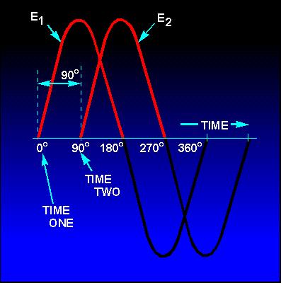
12 Wave-properties Signal Characteristics Analog (continuous) or digital (discrete) Periodic or aperiodic Components of a periodic electromagnet wave signal n Amplitude (maximum signal strength) e.g., in V n Frequency (rate at which the a periodic signal repeats itself) expressed in Hz n Phase (measure of relative position in time within a single period) in deg or radian (π = 360 = 1 period) Periodic: S( t) = S( t + T) S( t) = Asin( πft + ϕ) ϕ = phase A = amplitude f = frequncy T = period = 1/ f

13 Sine Waves

 f = 5Kz f = 1Kz A dual")
 =")
14 Sound Wave Examples Each signal is represented by x(t) = sin (πf.t) f = 5Kz f = 1Kz A dual tone signal with f1 and f is represented by x(t) = sin (πf1.t) + sin (πf.t)
 n n Wavelength is the distance the signal travels")
 λ = vf λf=v T = 1/ f v = 3x10 8 m / sec Exact speed light through vacuum is")
15 Periodic Signal Characteristics The simplest signal is a sinusoidal wave A sine wave can be expressed in time or space (wavelength) n n Wavelength is the distance the signal travels over a single cycle Wavelength is a function of speed and depends on the medium (signal velocity) λ = vf λf=v T = 1/ f v = 3x10 8 m / sec Exact speed light through vacuum is 99,79,458 m/s
16 More about signals.
17 Taylor Series Complex signals are often broken into simple pieces Signal requirements n n n Can be expressed into simpler problems Is linear The first few terms can approximate the signal Example: The Taylor series of a real or complex function ƒ(x) is the power series
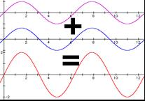
18 Signal Representation We can represent all complex signals as harmonic series of simpler signals Frequency components of the square wave with amplitude A can be expressed as s( t) 4 = A π K = 1/ odd sin(πkft) k
19 Square Wave S(t)=sin(πft) S(t)=1/3[sin(π(3f)t)] S(t)= 4/π{sin(πft) +1/3[sin(π(3f)t)]} s( t) = 4 A π K = 1/ odd sin(πkft) k
20 Square Wave K=1,3,5 K=1,3,5, 7 Frequency Components of Square Wave s( t) = 4 A π K = 1/ odd sin(πkft) k K=1,3,5, 7, 9,.. Fourier Expansion
21 Periodic Signals A Periodic signal/function can be approximated by a sum (possible infinite) sinusoidal signals. Consider a periodic signal with period T A periodic signal can be Real or Complex The fundamental frequency: ωo Example: n Prove that x(t) is periodic: Periodic Re al Complex ω T o o x( t) = π / T o = π / ω x( t) = cos( ω t + θ) o x( t + nt ) = x( t) = o = cos( ω t o Ae jω t o x( t) + θ )
22 Signal Generation No Modulation
23 Signal Generation - Modulated
24 RF Source

25 Frequency Spectrum We can plot the frequency spectrum or line spectrum of a signal n In Fourier Series k represent harmonics n Frequency spectrum is a graph that shows the amplitudes and/or phases of the Fourier Series coefficients Ck. Amplitude spectrum Ck =4A/k.pi The lines Ck are called line spectra because we indicate the values by lines s( t) = 4 A π K = 1/ odd sin(πkft) k
26 Examples
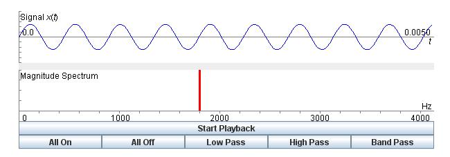
27 Periodic Signal Characteristics A signal can be made of many frequencies n All frequencies are multiple integer of the fundamental frequency n Spectrum of a signal identifies the range of frequencies the signal contains n Absolute bandwidth is defined as: Highest_Freq Lowest_Freq n 3-dB Bandwidth in general is defined as the frequency ranges where a signal has its most of energies Signal data rate n n n Information carrying capacity of a signal Expressed in bits per second (bps) Typically, the larger frequency à larger data rate Example à
28 Periodic Signal Characteristics Consider the following signal n Consists of two freq. component (f) and (3f) with BW = f S( t) = ( 4 / π) sin( πft) + ( 4 / 3π ) sin( π( 3 f ) t) Fundamental _ freq = f Max_ freq = 3 f Abs_ BW = 3 f f = f BW What is the Max amplitude of this component? f 3f
29 Calculating Signal Power Sinusoidal signals RMS (Root Mean Square) or effective value of the sine waveform (single tone): Average Power is calculated using RMS value and expressed in Watts Instantaneous power is V^/ V P = Vp / = V = RMS R RMS 0.707Vp Vp=Vpeak (not peak-to-peak) Read for more information:
30 RMS Concept Examples Find the Vrms for a square wave signal!
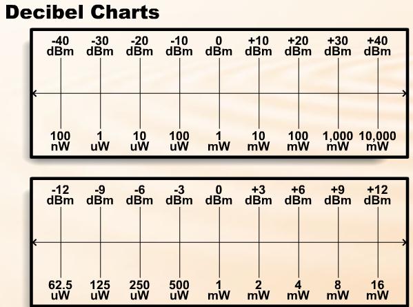
31 Power in Telecommunication Systems Power change can have large dynamic range Remember: x then x Hence 10 = y log(10 ) = log y x = Example 1: if P=mW and P1 = 1mW à 10log 10 (P/P1)=3.01 db Example : if P=1KW and P1=10W à 0dB What if db is given and you must find P/P1? n P/P1 = Antilog(dB/10) = 10 db/10. Example 3: if db is +10 what is P/P1? n P/P1 = Antilog(+10/10) = /10 = 10 log y We tend to express power in dbw or dbm
32 Converting and Amplification Watt, dbw, dbm, db Conversions: Watt to dbw & dbm P =10(W ) =10 log(10) =10dBW =10 log( mw /1mW ) =10 4 = 40dBm For more see:
33 dbm
34 Wireless Systems
35 Antenna An antenna is an electrical conductor (transducer) n Converts time-varying current/voltage signals into EM waves (and vise versa) Antennas RX and TX EM EM waves n Transmission - radiates electromagnetic energy into space n Reception - collects electromagnetic energy from space In two-way communication, the same antenna can be used for transmission and reception n Antenna characteristics are the same for transmitting or receiving electromagnetic energy The antenna can receive on one frequency and transmit on another
36 Isotropic Radiation We assume power is radiated spherically n The source be surrounded by a sphere or radius d n A perfect Omni directional power (isotropic antenna) We measure directionality based on how much of the isotropic radiation is focused in a certain direction n This is referred to as the antenna directionality or antenna Gain
 Received power (W): n n Also called power intercepted Aer is effective aperture or area (m^) n Aer is based on the physical area P r = P den = P t 4π d P t 4π d")
37 Isotropic Antenna A single source of transmission n Sphere of radiation with radius d n Uniform flux lines (just like the sun) Power flux density =P den = Transmit Power/A Sphere (W/m^) Received power (W): n n Also called power intercepted Aer is effective aperture or area (m^) n Aer is based on the physical area P r = P den = P t 4π d P t 4π d A er
38 Antenna Directionality or Gain Power density can be increased by changing its directionality n That is transmitting or receiving more in certain directions n This is referred to as the antenna gain (Gt) Equivalent Isotropic Radiated Power (EIRP) P r = P t G t 4π d A er = EIRP 4π d A er Let s discuss G, Ae, and EIRP!
 P r = P G t t")

39 Antenna Gain & Effective Area Power gain is expressed relative to isotropic (assume ohmic loss very small η=1; note: η>=1 ) P r = P G t t 4π d A er = EIRP 4π d A er Also known as Hertzian Dipole For Isotropic G = 4π η λ Ae = G λ 4π η A e = 4π f η c A e η is efficiency of the system (later)
40 Different Antenna Types
 n Pr = P den.")
 Also known as Range Eqn.")
41 Receiver Effective Area On the receiver side the larger the antenna the more of the radiated power can be captured (intercepted) n Pr = P den. Aer (in Watt) n Aer is the physical effective area of the receiver antenna P r = P t 4π d A er = P t G t G r = P t G t G r λ 4π d 1 4π (d / λ ) Also known as Range Eqn. Or Friis Or Free Space Eqn.
42 Antenna Gain & Effective Area P r = P t G t 4π d A er Both TX and RX antennas can have gains The receiver gain is directly related to its effective area n Note that larger Aeff à more gain à more power TX and RX Remember: G r = η 4π A er λ G t = η 4π A et λ η is efficiency of the system (later)
43 Equivalent Isotropic Radiated Power EIRP= Pt.Gt n Indicates signal strength radiated n Can be expressed in dbi or dbd dbi represents the power density with respect to an isotropic antenna dbd represents the power density with respect to a dipole antenna n Note: dbi = dbd +.15dB For example: n Calculate EIRP if a 1 dbi gain antenna is fed with 15 dbm of power 1 dbi + 15dBm = 7 dbm (500 mw)

 and η=1: n Find the gain and its effective area.")
/(c*c)")
44 Example: Antenna Gain Given a parabolic antenna with radius of 1 meter used to send WiFi (80.11b) channel ; Assume the effective area of the parabolic is 0.56A(Face Area) and η=1: n Find the gain and its effective area. n What is the gain in db? MATLAB CODE: Face_Area=0.56*pi*r*r; f=.417*10^9; c=3*10^8; l=c/f Gain=(4*pi*Face_Area*f*f)/(c*c) Gain_in_db=10*log10(Gain) G 4πA λ 4πf c See next slide for freq. bands in b = e = A e
45 Example: Antenna Gain 80.11b Frequency Band (GHz) In the United States and Canada there are 11 channels available for use in the 80.11b.4GHz WiFi Frequency range. This standard is defined by the IEEE. Average

46 Receiver Sensitivity GPS Receiver What is the minimum level of signal power the receiver can receive and still process it properly? P r (min) = P G t t 4πd A P (min) = P G G λ t t r er r η(4πd) In this case, given d à we find Pr(min)
47 Maximum Distance Covered Using sensitivity: min max ) (4 ) (4 4 r t t t r t t r r t t r P G G P d d G G P P A d G P P = = = π η λ π η λ π η=1 if no ohmic loss!
48 Sensitivity and RSSI Remember: EIRP à signal strength radiated Power strength can be adjusted in the routers/wireless devices There are two well-known values for link quality estimation: n n Received Signal Strength Indicator (RSSI) Determines the total energy of the signal Higher RSSI à more signal energy Higher RSSI à less packet error ratio (PER) Link Quality Indicator (LQI) Measurement is performed per packet No standard as to how to implement RSSI n Difficult to compare performances of difference devices to one another
49 Example: Power Transmission in XBEE XBEE has a threshold sensitivity of -44dBm and it can transmit with maximum of 10 dbm. What is the maximum distance two XBEE transceivers can be separated from one another? (assume: free space, Gt=Gr=1; no ohmic loss, f=.417ghz) d max = P max t G G t r ( 4π ) P min r η λ
50 Signal Distortion n n n Received signal conditions must have sufficient strength so that circuitry in the receiver can interpret the signal must maintain a level sufficiently higher than noise to be received without error Signal can be distorted: (1) High Noise; () Low Signal Strength Low Signal Strength is due to Attenuation (loss of energy) There are many sources contributing to signal attenuation Strength of signal falls off with distance over transmission medium (free space) à Free Space Loss (signal spreading) Ohmic loss converting to heat Note: Equalizing attenuation improves distortion By equalizing we can ensure that the signal performs the same over the entire frequency band
51 Loss in Free Space Model Note that Lpath is the loss due to signal spreading as it travels (not due to converting to heat or ohmic loss) Note: n as wave length increases more loss occurs n the impact of distance and wavelength are very drastic P L r = path EIRP G = (4π ) r (4π ) ( d / λ ) 1 ( d How does loss changes as the frequency increases? / λ )
52 Free Space Loss The signal disperses with distance Free space loss, for ideal isotropic antenna L path = P t P r = ( ) 4πd ( 4πfd) λ P t = signal power at transmitting antenna P r = signal power at receiving antenna λ = carrier wavelength d = propagation distance between antennas c = speed of light (» 3 10^8 m/s) where d and λ are in the same units (e.g., meters) = c When there is loss (db)à we have to subtract!
53 Free Space Loss (in db) Free space loss equation can be represented as L path_ db P P t = 10log = 0log ; r 4πd λ P t P r ( λ) + 0log( ) 1.98 db = 0 log d + Attenuation (loss) is greater at higher frequencies, causing distortion
54 Other Factors Impacting Attenuation Mismatch between the source and antenna Propagation loss (passing though walls) Absorption (due to hitting building) Antenna ohmic loss (converting to heat) P r = EIRP G L sys = L 1 L L = r ( 1/ L ) (1/ L path sys n L i i L sys _ db =10 log(l 1 )+10log(L )+10 log(l )+... )
55 Free Space Loss: A different view P = EIRP G r r (4π ) 1 ( d / λ ) Free space loss accounting for gain of other antennas P ( ) ( ) ( ) 4π d λd ( cd ) t Lend to end = = η = η = η Pr GrGtλ Aer Aet f A er A et G t = gain of transmitting antenna G r = gain of receiving antenna A et = effective area of transmitting antenna A er = effective area of receiving antenna G G r t = = 4πA er λ 4πA et λ
56 ..Free Space Loss Free space loss accounting for gain of other antennas can be recast as P ( 4π ) ( d ) ( λd ) ( cd ) L t Lend to end = = η = η = η Pr GrGtλ Ar At f end to end _ db = 0log ( λ) + 0 log( d ) 10 log( A A ) ( f ) + 0log( d) 10log( A t A ) dB = r Note that as λ increases frequency decreases and Hence, the total attenuation increases! A A 0 log + r t t r
57 Free Space Loss and Frequency Note that, ASSUMING THERE IS NO GAIN CHANGE, as f increases the loss increases! L L end to end _ db end to end _ db = = L db 0log Pt = 10log P r 4πfd = 0log c ( λ) + 0 log( d ) 10 log( A A ) t r Two approaches ( f ) + 0log( d) 10log( A t A ) dB = r 0 log + Note that, IF WE ACCOUNT FOR GAIN, as frequency increases total attenuation decreases! Frequency impacts gain!
58 Efficiency We define the efficiency of antenna (system) using η eff n Note the total power transmitted: P r + P loss = P total η eff = P r Ptotal = P r Pr + P loss TX (Pt) RX (Pr) Electromagnetic Energy
59 Example: Find the received power in a cell phone Notes Refer to Notes Example A
60 Example: Compare the received power for different antennas Notes Refer to Notes Example B
61 References Stallings, William. Wireless Communications & Networks, /E. Pearson Education India, 009.Stallings, William. Wireless Communications & Networks, /E. Pearson Education India, 009. Black, Bruce A., et al. Introduction to wireless systems. Prentice Hall PTR, 008. Rappaport, Theodore S. Wireless communications: principles and practice. Vol.. New Jersey: Prentice Hall PTR, 1996.
Antennas and Propagation
 Mobile Networks Module D-1 Antennas and Propagation 1. Introduction 2. Propagation modes 3. Line-of-sight transmission 4. Fading Slides adapted from Stallings, Wireless Communications & Networks, Second
Antennas and Propagation. Chapter 5
 Antennas and Propagation Chapter 5 Introduction An antenna is an electrical conductor or system of conductors Transmission - radiates electromagnetic energy into space Reception - collects electromagnetic
Antennas and Propagation. Chapter 5
 Antennas and Propagation Chapter 5 Introduction An antenna is an electrical conductor or system of conductors Transmission - radiates electromagnetic energy into space Reception - collects electromagnetic
Antennas & Propagation. CSG 250 Fall 2007 Rajmohan Rajaraman
 Antennas & Propagation CSG 250 Fall 2007 Rajmohan Rajaraman Introduction An antenna is an electrical conductor or system of conductors o Transmission - radiates electromagnetic energy into space o Reception
Antennas and Propagation
 Antennas and Propagation Chapter 5 Introduction An antenna is an electrical conductor or system of conductors Transmission - radiates electromagnetic energy into space Reception - collects electromagnetic
Session2 Antennas and Propagation
 Wireless Communication Presented by Dr. Mahmoud Daneshvar Session2 Antennas and Propagation 1. Introduction Types of Anttenas Free space Propagation 2. Propagation modes 3. Transmission Problems 4. Fading
Antenna Parameters. Ranga Rodrigo. University of Moratuwa. December 15, 2008
 Antenna Parameters Ranga Rodrigo University of Moratuwa December 15, 2008 Ranga Rodrigo (University of Moratuwa) Antenna Parameters December 15, 2008 1 / 47 Summary of Last Week s Lecture 90 o Radiation
Introduction to Telecommunications and Computer Engineering Unit 3: Communications Systems & Signals
 Introduction to Telecommunications and Computer Engineering Unit 3: Communications Systems & Signals Syedur Rahman Lecturer, CSE Department North South University syedur.rahman@wolfson.oxon.org Acknowledgements
Chapter 3 Data Transmission COSC 3213 Summer 2003
 Chapter 3 Data Transmission COSC 3213 Summer 2003 Courtesy of Prof. Amir Asif Definitions 1. Recall that the lowest layer in OSI is the physical layer. The physical layer deals with the transfer of raw
The quality of the transmission signal The characteristics of the transmission medium. Some type of transmission medium is required for transmission:
 Data Transmission The successful transmission of data depends upon two factors: The quality of the transmission signal The characteristics of the transmission medium Some type of transmission medium is
Project = An Adventure : Wireless Networks. Lecture 4: More Physical Layer. What is an Antenna? Outline. Page 1
 Project = An Adventure 18-759: Wireless Networks Checkpoint 2 Checkpoint 1 Lecture 4: More Physical Layer You are here Done! Peter Steenkiste Departments of Computer Science and Electrical and Computer
Antennas and Propagation
 CMPE 477 Wireless and Mobile Networks Lecture 3: Antennas and Propagation Antennas Propagation Modes Line of Sight Transmission Fading in the Mobile Environment Introduction An antenna is an electrical
Signal Characteristics
 Data Transmission The successful transmission of data depends upon two factors:» The quality of the transmission signal» The characteristics of the transmission medium Some type of transmission medium
EC 554 Data Communications
 EC 554 Data Communications Mohamed Khedr http://webmail. webmail.aast.edu/~khedraast.edu/~khedr Syllabus Tentatively Week 1 Week 2 Week 3 Week 4 Week 5 Week 6 Week 7 Week 8 Week 9 Week 10 Week 11 Week
TSEK02: Radio Electronics Lecture 6: Propagation and Noise. Ted Johansson, EKS, ISY
 TSEK02: Radio Electronics Lecture 6: Propagation and Noise Ted Johansson, EKS, ISY 2 Propagation and Noise - Channel and antenna: not in the Razavi book - Noise: 2.3 The wireless channel The antenna Signal
Lecture (01) Data Transmission (I)
 Data Transmission (I)") Agenda Lecture (01) Data Transmission (I) The objective Transmission terminologies Bandwidth and data rate Dr. Ahmed ElShafee ١ Dr. Ahmed ElShafee, ACU Spring 2016, Data Communication ٢ Dr. Ahmed ElShafee,
Agenda Lecture (01) Data Transmission (I) The objective Transmission terminologies Bandwidth and data rate Dr. Ahmed ElShafee ١ Dr. Ahmed ElShafee, ACU Spring 2016, Data Communication ٢ Dr. Ahmed ElShafee,
Lecture 2: SIGNALS. 1 st semester By: Elham Sunbu
 Lecture 2: SIGNALS 1 st semester 1439-2017 1 By: Elham Sunbu OUTLINE Signals and the classification of signals Sine wave Time and frequency domains Composite signals Signal bandwidth Digital signal Signal
Propagation mechanisms
 RADIO SYSTEMS ETIN15 Lecture no: 2 Propagation mechanisms Ove Edfors, Department of Electrical and Information Technology Ove.Edfors@eit.lth.se Contents Short on db calculations Basics about antennas Propagation
Introduction to wireless systems
 Introduction to wireless systems Wireless Systems a.a. 2014/2015 Un. of Rome La Sapienza Chiara Petrioli Department of Computer Science University of Rome Sapienza Italy Background- Wireless Systems What
Vehicle Networks. Wireless communication basics. Univ.-Prof. Dr. Thomas Strang, Dipl.-Inform. Matthias Röckl
 Vehicle Networks Wireless communication basics Univ.-Prof. Dr. Thomas Strang, Dipl.-Inform. Matthias Röckl Outline Wireless Signal Propagation Electro-magnetic waves Signal impairments Attenuation Distortion
CHAPTER 6 THE WIRELESS CHANNEL
 CHAPTER 6 THE WIRELESS CHANNEL These slides are made available to faculty in PowerPoint form. Slides can be freely added, modified, and deleted to suit student needs. They represent substantial work on
Chapter 4 The RF Link
 Chapter 4 The RF Link The fundamental elements of the communications satellite Radio Frequency (RF) or free space link are introduced. Basic transmission parameters, such as Antenna gain, Beamwidth, Free-space
Review of Lecture 2. Data and Signals - Theoretical Concepts. Review of Lecture 2. Review of Lecture 2. Review of Lecture 2. Review of Lecture 2
 Data and Signals - Theoretical Concepts! What are the major functions of the network access layer? Reference: Chapter 3 - Stallings Chapter 3 - Forouzan Study Guide 3 1 2! What are the major functions
Elements of Communication System Channel Fig: 1: Block Diagram of Communication System Terminology in Communication System
 Content:- Fundamentals of Communication Engineering : Elements of a Communication System, Need of modulation, electromagnetic spectrum and typical applications, Unit V (Communication terminologies in communication
Mobile and Wireless Networks Course Instructor: Dr. Safdar Ali
 Mobile and Wireless Networks Course Instructor: Dr. Safdar Ali BOOKS Text Book: William Stallings, Wireless Communications and Networks, Pearson Hall, 2002. BOOKS Reference Books: Sumit Kasera, Nishit
Data and Computer Communications Chapter 3 Data Transmission
 Data and Computer Communications Chapter 3 Data Transmission Eighth Edition by William Stallings Transmission Terminology data transmission occurs between a transmitter & receiver via some medium guided
Adapted from Dr. Joe Montana (George mason University) Dr. James
 Dr. James") ink Budget Adapted from Dr. Joe Montana (George mason University) Dr. James W. apean course notes Dr. Jeremy Allnutt course notes And some internet resources + Tim Pratt book 1 ink Power Budget Tx EIRP
ink Budget Adapted from Dr. Joe Montana (George mason University) Dr. James W. apean course notes Dr. Jeremy Allnutt course notes And some internet resources + Tim Pratt book 1 ink Power Budget Tx EIRP
Lecture 2 Physical Layer - Data Transmission
 DATA AND COMPUTER COMMUNICATIONS Lecture 2 Physical Layer - Data Transmission Mei Yang Based on Lecture slides by William Stallings 1 DATA TRANSMISSION The successful transmission of data depends on two
Data Communication. Chapter 3 Data Transmission
 Data Communication Chapter 3 Data Transmission ١ Terminology (1) Transmitter Receiver Medium Guided medium e.g. twisted pair, coaxial cable, optical fiber Unguided medium e.g. air, water, vacuum ٢ Terminology
ELEC 425 Interference Control in Electronics Lecture 7(a) Introduction to Antennas: Terminology
 Introduction to Antennas: Terminology") Dr. Gregory J. Mazzaro Fall 017 ELEC 45 Interference Control in Electronics Lecture 7(a) Introduction to Antennas: Terminology Chapter 9 THE CITADEL, THE MILITARY COLLEGE OF SOUTH CAROLINA 171 Moultrie
Dr. Gregory J. Mazzaro Fall 017 ELEC 45 Interference Control in Electronics Lecture 7(a) Introduction to Antennas: Terminology Chapter 9 THE CITADEL, THE MILITARY COLLEGE OF SOUTH CAROLINA 171 Moultrie
TSEK02: Radio Electronics Lecture 6: Propagation and Noise. Ted Johansson, EKS, ISY
 TSEK02: Radio Electronics Lecture 6: Propagation and Noise Ted Johansson, EKS, ISY 2 Propagation and Noise - Channel and antenna: not in the Razavi book - Noise: 2.3 The wireless channel The antenna Signal
Dr. John S. Seybold. November 9, IEEE Melbourne COM/SP AP/MTT Chapters
 Antennas Dr. John S. Seybold November 9, 004 IEEE Melbourne COM/SP AP/MTT Chapters Introduction The antenna is the air interface of a communication system An antenna is an electrical conductor or system
Data Transmission. ITS323: Introduction to Data Communications. Sirindhorn International Institute of Technology Thammasat University ITS323
 ITS323: Introduction to Data Communications Sirindhorn International Institute of Technology Thammasat University Prepared by Steven Gordon on 23 May 2012 ITS323Y12S1L03, Steve/Courses/2012/s1/its323/lectures/transmission.tex,
Outline / Wireless Networks and Applications Lecture 3: Physical Layer Signals, Modulation, Multiplexing. Cartoon View 1 A Wave of Energy
 Outline 18-452/18-750 Wireless Networks and Applications Lecture 3: Physical Layer Signals, Modulation, Multiplexing Peter Steenkiste Carnegie Mellon University Spring Semester 2017 http://www.cs.cmu.edu/~prs/wirelesss17/
Chapter 3 Solution to Problems
 Chapter 3 Solution to Problems 1. The telemetry system of a geostationary communications satellite samples 100 sensors on the spacecraft in sequence. Each sample is transmitted to earth as an eight-bit
Mobile Communications
 Mobile Communications Part IV- Propagation Characteristics Professor Z Ghassemlooy School of Computing, Engineering and Information Sciences University of Northumbria U.K. http://soe.unn.ac.uk/ocr Contents
Noise and Propagation mechanisms
 2 Noise and Propagation mechanisms Noise Johnson-Nyquist noise Physical review 1928 V rms2 = 4kTBR k : Bolzmann s constant T : absolute temperature B : bandwidth R : Resistance P=4kTB 1 1 Why is this a
Radio Propagation Fundamentals
 Radio Propagation Fundamentals Concept of Electromagnetic Wave Propagation Mechanisms Modes of Propagation Propagation Models Path Profiles Link Budget Fading Channels Electromagnetic (EM) Waves EM Wave
Noise and Interference Limited Systems
 Chapter 3 Noise and Interference Limited Systems 47 Basics of link budgets Link budgets show how different components and propagation processes influence the available SNR Link budgets can be used to compute
The Radio Channel. COS 463: Wireless Networks Lecture 14 Kyle Jamieson. [Parts adapted from I. Darwazeh, A. Goldsmith, T. Rappaport, P.
 The Radio Channel COS 463: Wireless Networks Lecture 14 Kyle Jamieson [Parts adapted from I. Darwazeh, A. Goldsmith, T. Rappaport, P. Steenkiste] Motivation The radio channel is what limits most radio
Data Communications & Computer Networks
 Data Communications & Computer Networks Chapter 3 Data Transmission Fall 2008 Agenda Terminology and basic concepts Analog and Digital Data Transmission Transmission impairments Channel capacity Home Exercises
UNIT Explain the radiation from two-wire. Ans: Radiation from Two wire
 UNIT 1 1. Explain the radiation from two-wire. Radiation from Two wire Figure1.1.1 shows a voltage source connected two-wire transmission line which is further connected to an antenna. An electric field
Range Considerations for RF Networks
 TI Technology Days 2010 Range Considerations for RF Networks Richard Wallace Abstract The antenna can be one of the most daunting components of wireless designs. Most information available relates to large
Announcements : Wireless Networks Lecture 3: Physical Layer. Bird s Eye View. Outline. Page 1
 Announcements 18-759: Wireless Networks Lecture 3: Physical Layer Please start to form project teams» Updated project handout is available on the web site Also start to form teams for surveys» Send mail
Introduction to Analog And Digital Communications
 Introduction to Analog And Digital Communications Second Edition Simon Haykin, Michael Moher Chapter 11 System and Noise Calculations 11.1 Electrical Noise 11.2 Noise Figure 11.3 Equivalent Noise Temperature
UNIT- 7. Frequencies above 30Mhz tend to travel in straight lines they are limited in their propagation by the curvature of the earth.
 UNIT- 7 Radio wave propagation and propagation models EM waves below 2Mhz tend to travel as ground waves, These wave tend to follow the curvature of the earth and lose strength rapidly as they travel away
Methodology for Analysis of LMR Antenna Systems
 Methodology for Analysis of LMR Antenna Systems Steve Ellingson June 30, 2010 Contents 1 Introduction 2 2 System Model 2 2.1 Receive System Model................................... 2 2.2 Calculation of
MSIT 413: Wireless Technologies Week 3
 MSIT 413: Wireless Technologies Week 3 Michael L. Honig Department of EECS Northwestern University January 2016 Why Study Radio Propagation? To determine coverage Can we use the same channels? Must determine
Announcement : Wireless Networks Lecture 3: Physical Layer. A Reminder about Prerequisites. Outline. Page 1
 Announcement 18-759: Wireless Networks Lecture 3: Physical Layer Peter Steenkiste Departments of Computer Science and Electrical and Computer Engineering Spring Semester 2010 http://www.cs.cmu.edu/~prs/wirelesss10/
Narrow- and wideband channels
 RADIO SYSTEMS ETIN15 Lecture no: 3 Narrow- and wideband channels Ove Edfors, Department of Electrical and Information technology Ove.Edfors@eit.lth.se 2012-03-19 Ove Edfors - ETIN15 1 Contents Short review
Contents. ITS323: Introduction to Data Communications CSS331: Fundamentals of Data Communications. Transmission Media and Spectrum.
 2 ITS323: Introduction to Data Communications CSS331: Fundamentals of Data Communications Sirindhorn International Institute of Technology Thammasat University Prepared by Steven Gordon on 3 August 2015
ITS323: Introduction to Data Communications CSS331: Fundamentals of Data Communications
 ITS323: Introduction to Data Communications CSS331: Fundamentals of Data Communications Sirindhorn International Institute of Technology Thammasat University Prepared by Steven Gordon on 3 August 2015
Chapter 2. Signals and Spectra
 Chapter 2 Signals and Spectra Outline Properties of Signals and Noise Fourier Transform and Spectra Power Spectral Density and Autocorrelation Function Orthogonal Series Representation of Signals and Noise
Chapter 3 Data Transmission
 Chapter 3 Data Transmission COSC 3213 Instructor: U.T. Nguyen 1 9/27/2007 3:21 PM Terminology (1) Transmitter Receiver Medium Guided medium e.g. twisted pair, optical fiber Unguided medium e.g. air, water,
Ultra Wide Band Signal Simulations Using FDTD Method
 Ultra Wide Band Signal Simulations Using FDTD Method Kazimierz Kai Siwiak Time Domain Corporation Tadeusz M. Babij Florida International University 27-28 September 2001 The Boston Marriott Hotel Newton,
Half-Wave Dipole. Radiation Resistance. Antenna Efficiency
 Antennas Simple Antennas Isotropic radiator is the simplest antenna mathematically Radiates all the power supplied to it, equally in all directions Theoretical only, can t be built Useful as a reference:
August, Antennas 101: A Course in RF Basics
 August, 2012 Antennas 101: A Course in RF Basics Antenna Basics Agenda: In today s training, we will go over a brief summary of the following topics at a basic level: Electromagnetic Waves Frequency and
Final Examination. 22 April 2013, 9:30 12:00. Examiner: Prof. Sean V. Hum. All non-programmable electronic calculators are allowed.
 UNIVERSITY OF TORONTO FACULTY OF APPLIED SCIENCE AND ENGINEERING The Edward S. Rogers Sr. Department of Electrical and Computer Engineering ECE 422H1S RADIO AND MICROWAVE WIRELESS SYSTEMS Final Examination
Antenna and Noise Concepts
 Antenna and Noise Concepts 1 Antenna concepts 2 Antenna impedance and efficiency 3 Antenna patterns 4 Receiving antenna performance Levis, Johnson, Teixeira (ESL/OSU) Radiowave Propagation August 17, 2018
Chapter 3. Data Transmission
 Chapter 3 Data Transmission Reading Materials Data and Computer Communications, William Stallings Terminology (1) Transmitter Receiver Medium Guided medium (e.g. twisted pair, optical fiber) Unguided medium
ANTENNAS AND WAVE PROPAGATION EC602
 ANTENNAS AND WAVE PROPAGATION EC602 B.Tech Electronics & Communication Engineering, Semester VI INSTITUTE OF TECHNOLOGY NIRMA UNIVERSITY 1 Lesson Planning (L-3,P-2,C-4) Chapter No. Name Hours 1. Basic
Antenna Fundamentals Basics antenna theory and concepts
 Antenna Fundamentals Basics antenna theory and concepts M. Haridim Brno University of Technology, Brno February 2017 1 Topics What is antenna Antenna types Antenna parameters: radiation pattern, directivity,
An Introduction to Antennas
 May 11, 010 An Introduction to Antennas 1 Outline Antenna definition Main parameters of an antenna Types of antennas Antenna radiation (oynting vector) Radiation pattern Far-field distance, directivity,
Basic Propagation Theory
 S-7.333 POSTGRADUATE COURSE IN RADIO COMMUNICATIONS, AUTUMN 4 1 Basic Propagation Theory Fabio Belloni S-88 Signal Processing Laboratory, HUT fbelloni@hut.fi Abstract In this paper we provide an introduction
2.5.3 Antenna Temperature
 ECEn 665: Antennas and Propagation for Wireless Communications 36.5.3 Antenna Temperature We now turn to thermal noise received by an antenna. An antenna in a warm environment receives not only a signal
Narrow- and wideband channels
 RADIO SYSTEMS ETIN15 Lecture no: 3 Narrow- and wideband channels Ove Edfors, Department of Electrical and Information technology Ove.Edfors@eit.lth.se 27 March 2017 1 Contents Short review NARROW-BAND
Chapter 2. Fundamental Properties of Antennas. ECE 5318/6352 Antenna Engineering Dr. Stuart Long
 Chapter Fundamental Properties of Antennas ECE 5318/635 Antenna Engineering Dr. Stuart Long 1 IEEE Standards Definition of Terms for Antennas IEEE Standard 145-1983 IEEE Transactions on Antennas and Propagation
Unit 3 - Wireless Propagation and Cellular Concepts
 X Courses» Introduction to Wireless and Cellular Communications Unit 3 - Wireless Propagation and Cellular Concepts Course outline How to access the portal Assignment 2. Overview of Cellular Evolution
RECOMMENDATION ITU-R S.1512
 Rec. ITU-R S.151 1 RECOMMENDATION ITU-R S.151 Measurement procedure for determining non-geostationary satellite orbit satellite equivalent isotropically radiated power and antenna discrimination The ITU
Contents. Telecom Service Chae Y. Lee. Data Signal Transmission Transmission Impairments Channel Capacity
 Data Transmission Contents Data Signal Transmission Transmission Impairments Channel Capacity 2 Data/Signal/Transmission Data: entities that convey meaning or information Signal: electric or electromagnetic
Wireless Communication System
 Wireless Communication System Generic Block Diagram An t PC An r Source Tx Rx Destination P t G t L p G r P r Source a source of information to be transmitted Destination a destination of the transmitted
Antennas and Propagation. Chapter 4: Antenna Types
 Antennas and Propagation : Antenna Types 4.4 Aperture Antennas High microwave frequencies Thin wires and dielectrics cause loss Coaxial lines: may have 10dB per meter Waveguides often used instead Aperture
Data Communications and Networks
 Data Communications and Networks Abdul-Rahman Mahmood http://alphapeeler.sourceforge.net http://pk.linkedin.com/in/armahmood abdulmahmood-sss twitter.com/alphapeeler alphapeeler.sourceforge.net/pubkeys/pkey.htm
RF Design Final Spring 2005
 RF Design Final Spring 2005 Name: LAST 4 NUMBERS in Student Number: Do NOT begin until told to do so Make sure that you have all pages before starting Open notes, NO CELL PHONES/WIRELESS DEVICES DO ALL
CHAPTER 5 THEORY AND TYPES OF ANTENNAS. 5.1 Introduction
 CHAPTER 5 THEORY AND TYPES OF ANTENNAS 5.1 Introduction Antenna is an integral part of wireless communication systems, considered as an interface between transmission line and free space [16]. Antenna
COMP211 Physical Layer
 COMP211 Physical Layer Data and Computer Communications 7th edition William Stallings Prentice Hall 2004 Computer Networks 5th edition Andrew S.Tanenbaum, David J.Wetherall Pearson 2011 Material adapted
Mobile Radio Propagation Channel Models
 Wireless Information Transmission System Lab. Mobile Radio Propagation Channel Models Institute of Communications Engineering National Sun Yat-sen University Table of Contents Introduction Propagation
Link Budget Calculation
 Link Budget Calculation Training materials for wireless trainers This 60 minute talk is about estimating wireless link performance by using link budget calculations. It also introduces the Radio Mobile
Satellite Signals and Communications Principles. Dr. Ugur GUVEN Aerospace Engineer (P.hD)
") Satellite Signals and Communications Principles Dr. Ugur GUVEN Aerospace Engineer (P.hD) Principle of Satellite Signals In essence, satellite signals are electromagnetic waves that travel from the satellite
Satellite Signals and Communications Principles Dr. Ugur GUVEN Aerospace Engineer (P.hD) Principle of Satellite Signals In essence, satellite signals are electromagnetic waves that travel from the satellite
ANTENNAS 101 An Introduction to Antennas for Ham Radio. Lee KD4RE
 ANTENNAS 101 An Introduction to Antennas for Ham Radio Lee KD4RE Prepared for Presentation at the Vienna Wireless Society, 13 January 2017 So What is an Antenna Anyway? We are all familiar with wire antennas
Antennas and Propagation. Prelude to Chapter 4 Propagation
 Antennas and Propagation Prelude to Chapter 4 Propagation Introduction An antenna is an electrical conductor or system of conductors for: Transmission - radiates electromagnetic energy into space (involves
Channel Characteristics and Impairments
 ELEX 3525 : Data Communications 2013 Winter Session Channel Characteristics and Impairments is lecture describes some of the most common channel characteristics and impairments. A er this lecture you should
UNIT Write short notes on travelling wave antenna? Ans: Travelling Wave Antenna
 UNIT 4 1. Write short notes on travelling wave antenna? Travelling Wave Antenna Travelling wave or non-resonant or aperiodic antennas are those antennas in which there is no reflected wave i.e., standing
E-716-A Mobile Communications Systems. Lecture #2 Basic Concepts of Wireless Transmission (p1) Instructor: Dr. Ahmad El-Banna
 Instructor: Dr. Ahmad El-Banna") October 2014 Ahmad El-Banna Integrated Technical Education Cluster At AlAmeeria E-716-A Mobile Communications Systems Lecture #2 Basic Concepts of Wireless Transmission (p1) Instructor: Dr. Ahmad El-Banna
October 2014 Ahmad El-Banna Integrated Technical Education Cluster At AlAmeeria E-716-A Mobile Communications Systems Lecture #2 Basic Concepts of Wireless Transmission (p1) Instructor: Dr. Ahmad El-Banna
9.4 Temporal Channel Models
 ECEn 665: Antennas and Propagation for Wireless Communications 127 9.4 Temporal Channel Models The Rayleigh and Ricean fading models provide a statistical model for the variation of the power received
RADIOMETRIC TRACKING. Space Navigation
 RADIOMETRIC TRACKING Space Navigation Space Navigation Elements SC orbit determination Knowledge and prediction of SC position & velocity SC flight path control Firing the attitude control thrusters to
Signals. Periodic vs. Aperiodic. Signals
 Signals 1 Periodic vs. Aperiodic Signals periodic signal completes a pattern within some measurable time frame, called a period (), and then repeats that pattern over subsequent identical periods R s.
Antennas and Propagation. Chapter 6a: Propagation Definitions, Path-based Modeling
 Antennas and Propagation a: Propagation Definitions, Path-based Modeling Introduction Propagation How signals from antennas interact with environment Goal: model channel connecting TX and RX Antennas and
Antenna & Propagation. Basic Radio Wave Propagation
 For updated version, please click on http://ocw.ump.edu.my Antenna & Propagation Basic Radio Wave Propagation by Nor Hadzfizah Binti Mohd Radi Faculty of Electric & Electronics Engineering hadzfizah@ump.edu.my
6 Radio and RF. 6.1 Introduction. Wavelength (m) Frequency (Hz) Unit 6: RF and Antennas 1. Radio waves. X-rays. Microwaves. Light
 Frequency (Hz) Unit 6: RF and Antennas 1. Radio waves. X-rays. Microwaves. Light") 6 Radio and RF Ref: http://www.asecuritysite.com/wireless/wireless06 6.1 Introduction The electromagnetic (EM) spectrum contains a wide range of electromagnetic waves, from radio waves up to X-rays (as
6 Radio and RF Ref: http://www.asecuritysite.com/wireless/wireless06 6.1 Introduction The electromagnetic (EM) spectrum contains a wide range of electromagnetic waves, from radio waves up to X-rays (as
Basic Radio Physics. Developed by Sebastian Buettrich. ItrainOnline MMTK 1
 Basic Radio Physics Developed by Sebastian Buettrich 1 Goals Understand radiation/waves used in wireless networking. Understand some basic principles of their behaviour. Apply this understanding to real
Modulation. Digital Data Transmission. COMP476 Networked Computer Systems. Analog and Digital Signals. Analog and Digital Examples.
 Digital Data Transmission Modulation Digital data is usually considered a series of binary digits. RS-232-C transmits data as square waves. COMP476 Networked Computer Systems Analog and Digital Signals
Fundamentals of Antennas. Prof. Ely Levine
 Fundamentals of Antennas Prof. Ely Levine levineel@zahav.net.il 1 Chapter 3 Wire Antennas 2 Types of Antennas 3 Isotropic Antenna Isotropic radiator is the simplest antenna mathematically Radiates all
Terminology (1) Chapter 3. Terminology (3) Terminology (2) Transmitter Receiver Medium. Data Transmission. Simplex. Direct link.
 Chapter 3. Terminology (3) Terminology (2) Transmitter Receiver Medium. Data Transmission. Simplex. Direct link.") Chapter 3 Data Transmission Terminology (1) Transmitter Receiver Medium Guided medium e.g. twisted pair, optical fiber Unguided medium e.g. air, water, vacuum Corneliu Zaharia 2 Corneliu Zaharia Terminology
Chapter 3 Data Transmission Terminology (1) Transmitter Receiver Medium Guided medium e.g. twisted pair, optical fiber Unguided medium e.g. air, water, vacuum Corneliu Zaharia 2 Corneliu Zaharia Terminology
Study of Factors which affect the Calculation of Co- Channel Interference in a Radio Link
 International Journal of Electronic and Electrical Engineering. ISSN 0974-2174 Volume 8, Number 2 (2015), pp. 103-111 International Research Publication House http://www.irphouse.com Study of Factors which
Experimental Evaluation Scheme of UWB Antenna Performance
 Tokyo Tech. Experimental Evaluation Scheme of UWB Antenna Performance Sathaporn PROMWONG Wataru HACHITANI Jun-ichi TAKADA TAKADA-Laboratory Mobile Communication Research Group Graduate School of Science
BROADBAND GAIN STANDARDS FOR WIRELESS MEASUREMENTS
 BROADBAND GAIN STANDARDS FOR WIRELESS MEASUREMENTS James D. Huff Carl W. Sirles The Howland Company, Inc. 4540 Atwater Court, Suite 107 Buford, Georgia 30518 USA Abstract Total Radiated Power (TRP) and
Data and Computer Communications. Tenth Edition by William Stallings
 Data and Computer Communications Tenth Edition by William Stallings Data and Computer Communications, Tenth Edition by William Stallings, (c) Pearson Education - Prentice Hall, 2013 Wireless Transmission
5.9 GHz V2X Modem Performance Challenges with Vehicle Integration
 5.9 GHz V2X Modem Performance Challenges with Vehicle Integration October 15th, 2014 Background V2V DSRC Why do the research? Based on 802.11p MAC PHY ad-hoc network topology at 5.9 GHz. Effective Isotropic
Channel Modeling and Characteristics
 Channel Modeling and Characteristics Dr. Farid Farahmand Updated:10/15/13, 10/20/14 Line-of-Sight Transmission (LOS) Impairments The received signal is different from the transmitted signal due to transmission