NBU-1012 Square pulse flashlamp driver User Manual
|
|
|
- Conrad Byrd
- 6 years ago
- Views:
Transcription
1 rev 1.07/ NBU-1012 Square pulse flashlamp driver User Manual
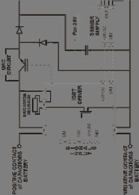
2 Overview / Applications Cooling NBU-1012 Square Pulse Flashlamp Driver is designed for simplification of solid-state laser systems development. Module forms flashlamp pulses of quasi-square shape using the energy stored in external capacitors bank. Special feature of the driver is built-in simmer module with complete triggering circuit for serial or external flashlamp triggering. NBU-1012 is intended for capacitor charging / pulse discharging applications such as pulsed laser systems. By default NBU-1012 is supplied in modification with serial triggering. Modification with external triggering is available on request (see Part number table). No external cooling is required.
3 Connections, signals, signal descriptions CAPACITORS: M6 studs C+ capacitor battery positive contact C capacitor battery negative contact FLASHLAMP: M6 studs LAMP+ positive flashlamp contact (anode) LAMP negative flashlamp contact (cathode) CM (TO CAPACITOR CHARGING MODULE): Molex PIN (color) DESIGNATION DESCRIPTION 1, 2, 3 (red) Positive CM Positive contact connection from charging module 4, 5, 6 (black or blue) Negative CM Negative contact connection from charging module +24 VDC (TO +24V POWER SUPPLY MODULE): Molex PIN (color) DESIGNATION DESCRIPTION 1, 2 (yellow) +24V DC Connect to these pins positive wire of 24V DC power supply for correct operations of NBU-1012 Regulation: 17 31V DC. Maximum input current: 4A 3, 4 (green) +24V DC Return Return from power supply producing +24V DC EXT (TO EXTERNAL TRIGGERING TRANSFORMER): Molex PIN (color) DESIGNATION DESCRIPTION 1, 2 Not Connected 3 Positive EXT Positive of triggering transformer primary winding 4 Negative EXT Negative of triggering transformer primary winding This connector is present in external triggering modification NBU-1012-EXT only
4 PWF (PULSE CONTROL): Molex PIN (color) DESIGNATION DESCRIPTION 1 (black) Interface Return Return Pulse and Discharge signals 2, 4, 7 Not Connected 3 (orange) Pulse 5 (green) Discharge Duration of +5V DC pulse at PIN3 completely defines IGBT-key open state time and, as consequence, flashlamp pulse duration While 0V voltage is applied to PIN5 (Discharge is ON), capacitor battery is continuously discharging on internal 1kOhm 50W resistor. While Discharge is ON capacitor charging power supply is blocked and capacitor charging is prohibited. While +5V DC voltage is applied to PIN5 (Discharge is OFF) module can be operated in the regular way. 6 (blue) Monitor Return Return Voltage Monitor signal 8 (red) Voltage Monitor Voltage measured at PIN8 is a monitor signal proportional to voltage on capacitor battery 0V at PIN8 corresponds to 0V on capacitor battery; 10V at PIN8 corresponds to maximal voltage value (1000V by default) on capacitor battery PWF CIRCUITS: PWF: Pulse PWF: Discharge PWF: Voltage Monitor 1k PIN 08 PIN 06

. Simmer will be maintained until 0V is applied to PIN3.")
5 SIM (SIMMER SUPPLY CONTROL): Molex PIN (color) DESIGNATION DESCRIPTION 1 (violet) Sensor Return Return Simmer Sensor signal 2 (yellow) Simmer Sensor 3 (red) Enable Simmer Sensor circuit is closed while simmer current flows through flashlamp and is open while simmer current is absent Since +5V DC voltage is applied to PIN3 embedded simmer supply tries to strike and maintain low-current discharge (simmer) in the flashlamp. If flashlamp triggering is failed simmer supply module tries to trigger it again with approximately 30 Hz repetition rate. After successful triggering the simmer supply can support up to 800mA flashlamp current (500mA is set by default). Simmer will be maintained until 0V is applied to PIN3. 4 (black) Enable Return Return Simmer Enable signal SIM CIRCUITS: SIM: Enable SIM: Simmer Sensor
6 Safety Warning! This equipment produces high voltages that can be very dangerous. Don t be careless around this equipment. During operation the protective covers of the equipment must be securely in place and all electrical connections must be properly attached NBU-1012 square pulse flashlamp driver is designed to be installed inside a properly grounded metal. It is the user s responsibility to ensure that personnel are prevented from accidentally contacting the NBU-1012, especially the CM Positive/Negative, C+/, LAMP+/ connectors and cable. Casual contact could be fatal! After shutdown, do not handle the capacitance load until it has been discharged. Use an appropriate meter to check for complete discharge. Disconnect the module from the DC power source before making or changing electrical or mechanical connections. Don t remove protective covers! There are no user serviceable parts inside this equipment.
7 Operations 1. Connect capacitor charging power supply, +24V DC power supply, capacitor battery and flashlamp to NBU-1012 module 2. Set +5V DC voltage on PIN5 of PWF to switch off capacitor bank discharging Warning! Normally capacitor discharging is on. So be careful and always switch off capacitor discharging before starting to charge capacitors. Otherwise it may lead to power supply failure. 3. Disable simmer supply (PIN3 of SIM) 4. Apply +24V DC power to the module 5. Enable your capacitor charging power supply (charging module). As soon as charging module starts operation, capacitors are charged 6. Enable simmer supply (set +5V DC on PIN3 of SIM) 7. Wait 5-10 seconds for Simmer Sensor. If it fails shut down your system 8. Disable your power supply before pulse Note that PCP and PCA-series power supplies are well-protected and it isn t obligatory to disable them. We recommend you to not disable PCP (PCA) at high on-off time ratio. 9. Set +5V DC pulse on PIN3 of PWF. This pulse duration defines IGBT-key open state time and flashlamp pulse width. 10. Enable your power supply after pulse 11. Repeat #8-#10 To power down NBU-1012 and discharge capacitor battery 1. Turn off or Disable your power supply 2. Set 0V on PIN5 of PWF to switch on capacitor bank discharging. Wait for complete discharge of capacitors. Warning! Don t use complete discharge of capacitor battery too often because of discharging resistor overheating 3. Remove +24V DC power from the module.
8 Specification +24VDC: Voltage regulations +24V DC +/ 7V Maximal power consumption 4A max CM: Maximal input voltage (maximal allowed capacitor charging 1000 V power supply output voltage) Maximal average input power 3000 W CAPACITORS BATTERY (C+, C-) Maximal current 600 A (1200 A within 1 ms pulse) Recommended wires LIFY 4 sq mm FLASHLAMP OUTPUT (LAMP+, LAMP-) Maximal current 600 A (1200 A within 1 ms pulse) Recommended wires LIFY 4 sq mm SIMMER PARAMETERS Current up to 800 ma Voltage up to 150 V Open Circuit Voltage up to 1350 V TRIGGERING PARAMETERS Voltage 20 kv negative pulse Pulse Width ~1 us Restrike Rate ~30 Hz Cooling No external cooling is required Protections From simultaneous capacitor battery charging and discharging (see Discharge signal description) From too short pulses (50us by default) From too long pulses (10ms by default) Environment: Operation temperature C Storage temperature C Humidity 90%, non-condensing Size (LxWxH) 210x198x52 mm Weight 3.0 kg
9 DRAWINGS M4 (x4)
10 Part number table Part Number NBU-1012 NBU-1012-EXT Triggering Serial External Modifications with non-standard simmer current for the NBU-1012 square pulse flashlamp driver are available on request. In that case Sxxx suffix should be added to the part number, where xxx means required simmer current in ma (from 300 to 800, 500 by default) Example: NBU-1012-EXT-S400


11 System Flowchart (Serial triggering modification)
12 System Flowchart (External triggering modification) NBU-1012-EXT module LAMP + EXT + EXT - LAMP Triggering transformer flashlamp - With external triggering modification NBU-1012-EXT we supply triggering transformer as it shown at drawing. Of course you may use any other construction of triggering transformer.
QBU series Pockels cell driver
 rev 1.14 / 2017 04 14 QBU series Pockels cell driver User manual Warning! This equipment produces high voltages that can be very dangerous. Please read user manual before starting operations. Important
Electro Optical Components, Inc.
 Electro Optical Components, Inc. 5460 Skylane Boulevard, Santa Rosa, CA 95403 Toll Free: 855-EOC-6300 www.eoc-inc.com info@eoc-inc.com rev 1.01 / 2010 07 02 QBU-BT series Pockels cell driver User Manual
ELECTRONICS FOR PULSE PICKERS
 Rev. 3.07 / 2014 04 10 ELECTRONICS FOR PULSE PICKERS TABLE OF CONTENTS Description... 2 High voltage switches... 3 Appearance / dimensions... 3 Power ratings... 3 Interfaces... 4 Specifications... 6 How
USER MANUAL XLB-650 Short Arc Xenon Lamp Ballast
 26 Ward Hill Dr., Bradford, MA 01835 Phone: +1-978-241-8260 Fax: +1-978-241-8262 USER MANUAL XLB-650 Short Arc Xenon Lamp Ballast The XLB-650 Xenon lamp ballast is a very compact power supply designed
USER MANUAL XLB-2500 Short Arc Xenon Lamp Ballast
 USER MANUAL XLB-2500 Short Arc Xenon Lamp Ballast The XLB-2500 Xenon lamp ballast is a very compact power supply designed for OEM applications. The XLB-2500 is ideal for high power applications where economy
HPP Laser Diode Pulser
 The HPP laser diode pulser is a new concept in pulsed diode driver development. Designed to be used with the LDD series drivers as the power source, the HPP pulser can deliver up to 350 amps of output
LYRA 501 USER S MANUAL
 LYRA 501 USER S MANUAL D O R A D O e n e r g y Belgrade, February 2005 1 GENERAL DESCRIPTION 1.1. IMPORTANT NOTICE 2 TECHNICAL SPECIFICATIONS CONTENTS 2.1. INPUT (MAINS) 2.2. OUTPUT 2.3. ENVIROMENTAL CONDITIONS
MOXTEK. 50kV 10 Watt MAGNUM X-ray Source. X-ray Sources. Contents
 X-ray Sources 0kV 10 Watt MAGNUM X-ray Source Manual Contents MAGNUM X-ray Source Characteristics Initial Inspection and Handling Tube Setup Operating Conditions Operating Precautions and Warnings Operating
ADC5000 SERIES. AC/DC Switch Mode Power Supplies and Rectifiers for Industrial and Telecom Applications. 60W, 125W and 250 W
 ADC5000 SERIES AC/DC Switch Mode Power Supplies and Rectifiers for Industrial and Telecom Applications 60W, 125W and 250 W Input voltage 230/115 VAC voltages 12, 24, 36 or 48 VDC Statistical MTBF >3 000
DIGITAL MULTIMETER AUTORANGING
 MODEL: D03124 DIGITAL MULTIMETER AUTORANGING 1 CONTENTS Page Number Details 2 Introduction 2 What s Included 3 Important Safety Information 3 Symbol Guide 4 Overview 5 Buttons 5 Display Indicators 6 General
3 in 1 Laser Power Supply (diode driver + Q-switch driver + DC power supply of marking head)
") 3 in 1 Laser Power Supply (diode driver + Q-switch driver + DC power supply of marking head) In a diode pumped Nd:YAG laser marker, a diode driver, a Q-switch driver and a DC power supply are needed. They
3 in 1 Laser Power Supply (diode driver + Q-switch driver + DC power supply of marking head) In a diode pumped Nd:YAG laser marker, a diode driver, a Q-switch driver and a DC power supply are needed. They
CW Lamp Power Supply
 CW Lamp Power Supply The STCW series laser power supplies are made for CW lamp-pumped Nd:YAG lasers. The main circuit of the power supply is based on power electronic module IGBT, adopts PWM technique
IX6611 Evaluation Board
 IXUM6611-0716 The IX6611 Evaluation Board is created to simplify the IX6611 driver s accommodation in a new design. It is a standalone device that can be easily connected to any IGBT or MOSFET to evaluate
External RF Driver. Electrical Driver for AOTF-crystal. Instruction Manual
 External RF Driver Electrical Driver for AOTF-crystal Instruction Manual Table of Contents 1 General... 3 2 Compliance... 3 3 Labeling... 4 4 Interface... 5 4.1 Front Panel... 5 4.2 Back Panel... 6 4.2.1
Zürcherstrasse 70 -CH 8104 Weiningen Tel Fax P.O. Box 155 Switzerland
 Zürcherstrasse 70 -CH 8104 Weiningen Tel. + 41 44 750 63 63 Fax + 41 44 750 63 66 P.O. Box 155 Switzerland www.prescoag.com info@prescoag.com Table of contents 1 Safety precautions 1.1 Safety 1.2 Safety
User Manual LDP-V UF3. PicoLAS GmbH Company for Innovative Power Electronics and Laser Technology. Kaiserstrasse Herzogenrath
 User Manual LDP-V 03-100 UF3 PicoLAS GmbH Company for Innovative Power Electronics and Laser Technology Kaiserstrasse 100 52134 Herzogenrath Phone: Fax: E-Mail: Web: +49 (0) 2407-563 58-0 +49 (0) 2407-563
CD770 DIGITAL MULTIMETER INSTRUCTION MANUAL
 CD770 DIGITAL MULTIMETER INSTRUCTION MANUAL Table of Contents 1 SAFETY PRECAUTIONS Before use, read the following safety precautions.- 1-1 Explanation of Warning Symbols 001 1-2 Warning Messages for Safe
USER MANUAL LDY CW Diode Driver Power Supplies
 USER MANUAL LDY CW Diode Driver Power Supplies The LDY family of CW diode laser drivers is Lumina Power s second generation of high power laser diode drivers. As a laser diode driver, the LDY power supply
3 Circuit Theory. 3.2 Balanced Gain Stage (BGS) Input to the amplifier is balanced. The shield is isolated
 Input to the amplifier is balanced. The shield is isolated") Rev. D CE Series Power Amplifier Service Manual 3 Circuit Theory 3.0 Overview This section of the manual explains the general operation of the CE power amplifier. Topics covered include Front End Operation,
Rev. D CE Series Power Amplifier Service Manual 3 Circuit Theory 3.0 Overview This section of the manual explains the general operation of the CE power amplifier. Topics covered include Front End Operation,
High Intensity LED Stroboscope Digital Tachometer DT-361/365. Instruction manual. Be sure to read before use.
 98585A High Intensity LED Stroboscope Digital Tachometer DT-361/365 Instruction manual Be sure to read before use. Before use, please carefully read these safety precautions as well as instructions, and
Operator Manual 1.4 FRACSIM MINI
 FracSim Meters FracSim Meters was founded with the intention of providing specifically designed tools for the well service industry. Our goal is to provide quality tools with a robust design to meet the
AEI800L Avid extreme Liquid Cooled Inverter Module Data Sheet REV 00, March AEI800L Liquid Cooled Inverter Module Data Sheet
 AEI800L Avid extreme Liquid Cooled Inverter Module REV 00, March 2016 Avid Controls Inc. 41261 Park 290 Drive, Waller, TX 77484, USA info@avidcontrolsinc.com (+1) (281) 640-8600 Page 1 of 16 Copyright
D.C. BRUSHLESS MOTORS DRIVE. BLD07-IT Service Manual
 D.C. BRUSHLESS MOTORS DRIVE BLD07-IT Service Manual INTECNO s.r.l. Via Caduti di Sabbiuno n. 9/E 40011 Anzola Emilia (BO) - Italy tel. 051.19985350 fax 051.19985360 www.intecno-srl.com INDEX Description
WRM-10 TM TRANSFORMER WINDING RESISTANCE METER
 WRM-10 TM TRANSFORMER WINDING RESISTANCE METER USER S MANUAL Vanguard Instruments Company, Inc. 1520 S. Hellman Ave. Ontario, California 91761, USA TEL: (909) 923-9390 FAX: (909) 923-9391 June 2009 Revision
DSSIU-6-1U. Dedicated 6-channel system interface unit for ultra-stable, high precision fluxgate technology DS series current transducers.
 DSSIU-6-1U Dedicated 6-channel system interface unit for ultra-stable, high precision fluxgate technology DS series current transducers. Powers up to 6 x DS50 to DS2000 at the same time. Supports calibration
Presco AG. Peak Voltmeter. Type PVM-100. Instruction Manual. Table of contents
 Zürcherstrasse 70 -CH 8104 Weiningen Tel. + 41 44 750 63 63 Fax + 41 44 750 63 66 P.O. Box 155 Switzerland Email : info@prescoag.com Internet : www.prescoag.com Peak Voltmeter Type PVM-100 Instruction
Triple Voltage Regulator TLE 4471
 Triple Voltage Regulator TLE 4471 Features Triple Voltage Regulator Output Voltage 5 V with 450 ma Current Capability Two tracked Outputs for 50 ma and 100 ma Enable Function for main and tracked Output(s)
10 Error Code List. Motion Control SW. NTI AG / LinMot User Manual Motion Control SW/ Page 87/94
 Motion Control SW L i n M o t 10 List Code Description Actions to take 0000h No Error No error is pending. 0001h X4 Logic Supply Too Low The logic supply voltage has been too low. The minimal logic supply
Laser Electronics. Laser Synchronization Modules Pockels Cell Drivers Laser Diode Drivers Flashlamp Drivers Cooling Units Pump Chambers Crystal Ovens
 Laser Electronics Laser Synchronization Modules Pockels Cell Drivers Laser Diode Drivers Flashlamp Drivers Cooling Units Pump Chambers Crystal Ovens 2018 FEATURED Universal Laser Diode Driver unildd series
MG5223F S-Band Magnetron
 MG5223F S-Band Magnetron The data should be read in conjunction with the Magnetron Preamble. ABRIDGED DATA Fixed frequency pulse magnetron. Operating frequency... 3050 ± 10 MHz Typical peak output power...
TIG 250 AC-DC. POWER SOURCE art
 CEBORA S.p.A. 1 TIG 250 AC-DC POWER SOURCE art. 236.76 SERVICE MANUAL CEBORA S.p.A. 2 CONTENTS 1 - GENERAL INFORMATION... 3 1.1 - Introduction.... 3 1.2 - General service policy.... 3 1.3 - Safety information....
NANOSECOND PULSE GENERATOR NPG-18/3500(N) USER MANUAL
 USER MANUAL") NANOSECOND PULSE GENERATOR NPG-18/3500(N) USER MANUAL 2014 Megaimpulse Ltd. Copyright 2013 MEGAIMPULSE Ltd. All Rights Reserved. MEGAIMPULSE LTD. PROVIDES THIS MANUAL "AS IS" WITHOUT WARRANTY OF ANY KIND,
NANOSECOND PULSE GENERATOR NPG-18/3500(N) USER MANUAL 2014 Megaimpulse Ltd. Copyright 2013 MEGAIMPULSE Ltd. All Rights Reserved. MEGAIMPULSE LTD. PROVIDES THIS MANUAL "AS IS" WITHOUT WARRANTY OF ANY KIND,
HITEK POWER OLS10K SERIES
 10 KW HIGH VOLTAGE POWER SUPPLIES The HiTek Power OLS10K series range of single-output high voltage power supplies meets the exacting requirements found in electron-beam, ion-beam, and x-ray systems, as
EE-110 Introduction to Engineering & Laboratory Experience Saeid Rahimi, Ph.D. Lab Timer: Blinking LED Lights and Pulse Generator
 EE-110 Introduction to Engineering & Laboratory Experience Saeid Rahimi, Ph.D. Lab 9 555 Timer: Blinking LED Lights and Pulse Generator In many digital and analog circuits it is necessary to create a clock
Industrial motor controller for brushed DC motors 12 VDC
 Industrial motor controller for brushed DC motors 12 VDC Design for output currents up to 5 A Control with the following functions: - reversal of direction of rotation - rotational speed control (external)
Instruction Manual ICM 3091N Digital AC Clampmeter EN FR IT DE ES
 Instruction Manual ICM 3091N Digital AC Clampmeter EN FR IT DE ES TABLE OF CONTENTS / EN TITLE TABLE OF CONTENTS PAGE 1. SAFETY INFORMATION... 1 2. TECHNICAL SPECIFICATIONS... 2 3. PARTS & CONTROLS...
NDR6110 Single Channel Dynamic Driver for Piezoelectric Actuators
 NDR61 Driver Series NDR6110 Single Channel Dynamic Driver for Piezoelectric Actuators Features Bipolar and unipolar output load Galvanic separation of the output Adjustable input range and phase inversion
CPAT AFDD Operation Manual
 CPAT AFDD Operation Manual v 2.0 / 2008.08.12 Contents 1. FCC and IC Compliance Statements 3 2. System Components 4 3. AFDD Unit Physical Installation 5 4. Antennas Installation 6 5. Electrical Installation
Modbus Register Map: InfraStruXure Symmetra 3-Phase Absolute Starting Register Number, (Decimal)
") Modbus Map: InfraStruXure Symmetra 3-Phase 990-3249 // Status Word 0 40000 0 8 Reserved R = UPS ready to provide power to the load upon return of normal line voltage or upon user command = State == Enable
Modbus Map: InfraStruXure Symmetra 3-Phase 990-3249 // Status Word 0 40000 0 8 Reserved R = UPS ready to provide power to the load upon return of normal line voltage or upon user command = State == Enable
The latest version offers all the features already available in the IPoD series 8232 to 8238 and 8427 as well as providing several exclusive
 Power driving module for injectors using magnetoelectric technology. It features different driving modes and numerous advanced functions enabling it to adapt to most commercially available injectors. IPoD
1. General Instructions 2 2. Safety 2 3. Lamp Starting Test Instrument LSTI 5 3
 1. General Instructions 2 2. Safety 2 3. Lamp Starting Test Instrument LSTI 5 3 3.1. Components and Connections of the Front Panel (Fig. 1) 5 3.2. Connection of the Rear Panel (Fig. 2) 7 3.3. Operation
ULTRAVOLT TF SERIES HIGH VOLTAGE TEST FIXTURES
 ULTRAVOLT TF SERIES HIGH VOLTAGE TEST FIXTURES Reduced-size HV test fixture devices The TF series product line supports the need to make accurate measurements of high voltage power supply (HVPS) and HV
Artistic Licence. Candle-Power CP12. User Guide. Download this user guide by scanning the following QR code: Candle-Power CP12 User Guide Version 4-8
 Artistic Licence Candle-Power CP12 User Guide Download this user guide by scanning the following QR code: Version 4-8 Connections 1 2 3 4 5 6 4 5 6 Term DAT+ DAT- COM DAT+ DAT- COM DMX512 In DMX512 Loop
Model: &
 600A True RMS Digital Clamp Meter Model: 72-3097 & 72-3099 1 CONTENTS Page Number Details 3 Important Safety Information 4 Product overview 4 Key Functions 5 General Specification 5 Electrical Specification
Relay Driver Overview and Applications
 Relay Driver Overview and Applications Describes Basic and Advanced Settings for common and alternative/novel uses for the Relay driver (RD-1). Morningstar s Relay Driver (RD-1) is a fully programmable
CX1140 Hydrogen Thyratron
 CX1140 Hydrogen Thyratron The data to be read in conjunction with the Hydrogen Thyratron Preamble. ABRIDGED DATA Hydrogen-filled tetrode thyratron, featuring low jitter and low anode delay time drift.
PCX-9000 Series Datasheet
 PCX-9000 Series Datasheet PCX-9000 Series PULSED/CW LASER DIODE DRIVER Features: Up to 600A of Output Current Adjustable 60A bias (simmer current) PCX-9600-X 600Amps at 24 Volts Internal Trigger 2kHz-25KHz
High Voltage Power Supply s THESE PSU S ARE NO TOY S. KNOW WHAT YOU ARE DOING, AS THEY CAN KILL YOU.
 High Voltage Power Supply s 1/6 High Voltage Power Supply s THESE PSU S ARE NO TOY S. KNOW WHAT YOU ARE DOING, AS THEY CAN KILL YOU. MAKE SHURE THE POWER SUPPLY IS DISCONNECTED FROM THE MAIN AND THERE
Laser Electronics. Laser Synchronization Modules Pockels Cell Drivers Laser Diode Drivers Flashlamp Drivers Cooling Units Pump Chambers Crystal Ovens
 Laser Electronics Laser Synchronization Modules Pockels Cell Drivers Laser Diode Drivers Flashlamp Drivers Cooling Units Pump Chambers Crystal Ovens 2018 Featured Universal Laser Diode Driver unildd series
BMS BMU Vehicle Communications Protocol
 BMS Communications Protocol 2013 Tritium Pty Ltd Brisbane, Australia http://www.tritium.com.au 1 of 11 TABLE OF CONTENTS 1 Introduction...3 2 Overview...3 3 allocations...4 4 Data Format...4 5 CAN packet
Brushless DC Motor Controller Specification Assemblies 025F0248
 Brushless DC Motor Controller Specification Assemblies 025F0248 600A1099 Rev. B April 4 th, 2014 Revision History EC Date Description Rev EC54318 09/03/13 Initial Release A EC58093 04/04/14 Added cap discharge
Industrial motor controller for brushed DC motors 24 VDC
 Industrial motor controller for brushed DC motors 24 VDC Design for output currents up to 5 A Control with the following functions: - reversal of direction of rotation - open-loop speed control (external)
Power Supply Device (KLTE-430D) Installation & Operation Manual
 Installation & Operation Manual") 9-25-212 modified 6-3-216 KLTE-43DInstallation&Operation (1/15) Power Supply Device (KLTE-43D) Installation & Operation Manual Sept. 25, 212 KLTE-43DInstallation&Operation (2/15) Table of Contents < Rectifier
9-25-212 modified 6-3-216 KLTE-43DInstallation&Operation (1/15) Power Supply Device (KLTE-43D) Installation & Operation Manual Sept. 25, 212 KLTE-43DInstallation&Operation (2/15) Table of Contents < Rectifier
Datasheet (Preliminary) Modular Inverter System VARIS Datasheet VARIS
 Modular Inverter System VARIS Datasheet VARIS") Datasheet (Preliminary) Modular Inverter System VARIS -06-12 Individual circuit arrangement or forced air cooled 60µF capacitance per module Optical or electrical signal transmission Current and temperature
Datasheet (Preliminary) Modular Inverter System VARIS -06-12 Individual circuit arrangement or forced air cooled 60µF capacitance per module Optical or electrical signal transmission Current and temperature
Electronically Commutated (EC) Motor Control with Solo, Select and Sync PWM Boards
 Motor Control with Solo, Select and Sync PWM Boards") Electronically Commutated (EC) Motor Control with Solo, Select and Sync PWM Boards The Solo, Select and Sync PWM boards provide a pulse-width modulated (PWM) signal to the EC motor to control fan speed.
Electronically Commutated (EC) Motor Control with Solo, Select and Sync PWM Boards The Solo, Select and Sync PWM boards provide a pulse-width modulated (PWM) signal to the EC motor to control fan speed.
VARAN Stepper Module VST 012
 VARAN Stepper Module VST 012 The VST 012 is a VARAN module designed for the control of a stepper motor up to a maximum 10 A RMS. The available operating modes are full step, half step and micro step. The
CHAPTER MAINTENANCE AND TROUBLESHOOTING. In This Chapter... Maintenance and Inspection Troubleshooting...6 3
 CHAPTER MAINTENANCE AND 6 TROUBLESHOOTING In This Chapter... Maintenance and Inspection.................6 2 Monthly Inspection:..................................6 2 Annual Inspection....................................6
INFO-PTr. PT-100 Measuring Card. PT-100 Temperature Measurement. Technical Data
 PT-100 Temperature Measurement Technical Data The INFO-PT board is the measurement element for precise registration of temperatures. Up to 14 PT-100 sensors are connected via 4-wire lead directly to the
MODEL 25D MANUAL PRODUCT OVERVIEW:
 MODEL 25D MANUAL PRODUCT OVERVIEW: The Model 25D drive electronics is a high voltage push-pull power amplifier capable of output voltage swings in the order of 175v P-P, push-pull. The Model 25D provides
FREQUENCY-CONVERTER MFR 600A / 1500A Version 2
 Technical documentation for: FREQUENCY-CONVERTER MFR 600A / 1500A Version 2 Contents: 1. General description 2. Technical data 3. Function of the ramp generator 4. Electrical connection, examples for the
User instructions for CMS EE HV Distribution Crates [DEG 547] (including the associated control, input and output cards)
![User instructions for CMS EE HV Distribution Crates [DEG 547] (including the associated control, input and output cards)](/thumbs/86/94469061.jpg "User instructions for CMS EE HV Distribution Crates [DEG 547] (including the associated control, input and output cards)") User instructions for CMS EE HV Distribution Crates [DEG 547] (including the associated control, input and output cards) Version 2.1 : 20 th October 2011 1. Overview The DEG547 distribution crate, together
User instructions for CMS EE HV Distribution Crates [DEG 547] (including the associated control, input and output cards) Version 2.1 : 20 th October 2011 1. Overview The DEG547 distribution crate, together
Smart-house Dimmer Power dimmer up to 500W Type SH2D500W230
 Smart-house Dimmer Power dimmer up to 500W Type SH2D500W230 Universal dimmer switch for R, L, C up to 500W and LED loads Automatic load detection for L, R, C loads Integrated heat sink for temperature
Installation Tech Note Dallas, Texas
 AMC B40A40AC Installation Tech Note Dallas, Texas May, 2010 ! CAUTION! Do NOT apply air pressure to release the collet while the servo motor is rotating. The servo motor spindle must be FULLY STOPPED before
Ameritron ALS-600 Retrofit ALS-600-LPF Assembly Manual
 Ameritron ALS-600 Retrofit ALS-600-LPF Assembly Manual FEATURES Automatic band change based on TX frequency. PIN diode QSK RX/TX switch. Temperature controlled FAN for quiet operation. RS-232 serial port
Multifunction Digital
 MS2009A Multifunction Digital Clamp Meter User Manual 200/600 OFF 2/20 NCV SEL MAX V RAN HOLD OFF MS2009A AC CLAMP METER AUTO MAX C F kmω μmva CONTENTS Safety requirements...1 Safety signs...1 Notes...1
S D 1 Operating Instructions
 S D 1 Operating Instructions Volutronic 1. SAFETY 3 2. DESCRIPTION 4 3. CONNECTING THE SD1 5 3.1 Connecting the voltage supply 5 3.2 Connecting SD1 with rectangular output. 5 3.3 Connecting the SD1 with
PKG-232-MBC12-PS-CBL System Diagram and Specifications
 PKG-232-MBC12-PS-CBL System Diagram and Specifications Included Components: 23Y206S-LW8-MS Stepper Motor MBC12101 Stepper Driver PSA80V4A-1 Power Supply CBL-18AWG-04C-010-MS Motor Cable WIR-1007-18-YEL
NANOSECOND PULSE GENERATOR NPG-15/2000(N) USER MANUAL
 USER MANUAL") NANOSECOND PULSE GENERATOR NPG-15/2000(N) USER MANUAL 2013 Megaimpulse Ltd. Copyright 2013 MEGAIMPULSE Ltd. All Rights Reserved. MEGAIMPULSE LTD. PROVIDES THIS MANUAL "AS IS" WITHOUT WARRANTY OF ANY KIND,
NANOSECOND PULSE GENERATOR NPG-15/2000(N) USER MANUAL 2013 Megaimpulse Ltd. Copyright 2013 MEGAIMPULSE Ltd. All Rights Reserved. MEGAIMPULSE LTD. PROVIDES THIS MANUAL "AS IS" WITHOUT WARRANTY OF ANY KIND,
MRS ELECTRONIC DATASHEET CAN I/O AND PLC DESCRIPTION TECHNICAL DATA REGULATORY APPROVALS AND TESTING SOFTWARE/PROGRAMMING
 DESCRIPTION The versatile CAN I/O PLC with 14 inputs and outputs impresses with its compact design and its operating voltage range of 9 to 30 volts. It provides 8 I/Os that can be configured as inputs
Portable Appliance Testers. OmegaPAT MI 2140 BetaPAT MI 2141 User Manual Ver Code No
 Portable Appliance Testers OmegaPAT MI 2140 BetaPAT MI 2141 User Manual Ver. 1.2. Code No. 20 750 684 Distributor: Producer: METREL d.d. Ljubljanska 77 SI-1354 Horjul E-mail: metrel@metrel.si http://www.metrel.si
SONO 1500 CT Ultrasonic flow sensor
 Data sheet SONO 1500 CT Ultrasonic flow sensor Description/Application MID examination certificate no.: DE-09-MI004-PTB011 The SONO 1500 CT is an ultrasonic flow sensor especially designed for heating,
Digital Clamp Meter Model: &
 Digital Clamp Meter Model: 72-7224 & 72-7226 1 SAFETY INFORMATION Please read these instructions carefully before use and retain for future reference. This meter is designed to meet IEC61010-1, 61010-2-032,
PIN/PINLESS DEEP SENSING MOISTURE METER WITH SPHERICAL SENSOR AND REMOTE PROBE
 99 Washington Street Melrose, MA 02176 Phone 781-665-1400 Toll Free 1-800-517-8431 Visit us at www.testequipmentdepot.com PIN/PINLESS DEEP SENSING MOISTURE METER WITH SPHERICAL SENSOR AND REMOTE PROBE
Operating Instructions
 4XH35QB151210 Small General Frequency Converter Operating Instructions 220V 0.75KW 5.5KW 400V 0.75KW 15KW Please read the instruction carefully and understand the contents so that it can be installed and
312, 316, 318. Clamp Meter. Users Manual
 312, 316, 318 Clamp Meter Users Manual PN 1989445 July 2002 Rev.2, 2/06 2002, 2006 Fluke Corporation. All rights reserved. Printed in China. All product names are trademarks of their respective companies.
CBCT TM CIRCUIT BREAKER COIL TESTER
 CBCT TM CIRCUIT BREAKER COIL TESTER USER S MANUAL Vanguard Instruments Company, Inc. 1520 S. Hellman Ave. Ontario, California 91761, USA TEL: (909) 923-9390 FAX: (909) 923-9391 August 2010 Revision 1 SAFETY
HITEK POWER OL1K SERIES
 HIGH VOLTAGE POWER SUPPLY The HiTek Power OL1K Series range of single output high voltage power supplies meets the exacting requirements found in electron and ion beam systems, ion implantation and X-ray
SP483E. Enhanced Low EMI Half-Duplex RS-485 Transceiver
 SP483E Enhanced Low EMI Half-Duplex RS-485 Transceiver +5V Only Low Power BiCMOS Driver / Receiver Enable for Multi-Drop Configurations Enhanced ESD Specifications: +/-15kV Human Body Model +/-15kV IEC61000-4-2
X-band Magnetron. Cooling (note 5) Water Output coupling (note 6) UG51/U Magnet (note 7) Integral, Permanent
 Water Output coupling (note 6) UG51/U Magnet (note 7) Integral, Permanent") X-band Magnetron GENERAL DESCRIPTION MX7637 is a tunable X-band pulsed type magnetron intended primarily for linear accelerator. It is cooled with water and has a UG51/U (WR112) output coupling. It is
X-band Magnetron GENERAL DESCRIPTION MX7637 is a tunable X-band pulsed type magnetron intended primarily for linear accelerator. It is cooled with water and has a UG51/U (WR112) output coupling. It is
USER MANUAL. CW Diode Driver Power Supplies
 USER MANUAL CW Diode Driver Power Supplies The LDD-100/150/250 family of high power CW diode laser can be configured for output currents from as low as 10A to output current up to 80A at maximum power
IS-3000 SERIES INFRARED SCANNER
 IS-3000 SERIES INFRARED SCANNER NON-CONTACT, RELIABLE, PRECISE, LONG RANGE POSITIONING FOR HOT OR COLD PRODUCTS FEATURES ANALOG AND DIGITAL OUTPUTS INDICATIVE OF TARGET POSITION, WIDTH AND TEMPERATURE
Advantages. Applications
 LDD MLB High Mercury Power Lamp CW Laser Power Diode Supplies Drivers The MLB series Mercury lamp ballasts are designed for the OEM customer. MLB power supplies provide a precise constant power output
analog output inductive sensors analog output for distance control analog
 for distance control analog output inductive sensors KEY ADVANTAGES ü Highest sensing ranges ü Best temperature stability ü Excellent repeat accuracy ü Resolution in µm range Range overview Housing size
CONTENTS. SAFETY PRECAUTIONS: Before use, read the following safety precautions
 CONTENTS [1] SAFETY PRECAUTIONS: Before use, read the following safety precautions 2 [2] APPLICATION AND FEATURES 5 [3] NAME OF COMPONENT UNITS 6 [4] DESCRIPTION OF FUNCTIONS 8 [5] MEASUREMENT PROCEDURE
PHOENIX CONTACT
 Electronic circuit breaker CLIPLINE Data sheet 102898_en_03 PHOENIX CONTACT 2010-12-17 1 Description The electronic circuit breaker can be used in applications that cover all aspects of the switched-mode
L25 Series Operator Manual
 L25 Series Operator Manual L25 899-07001-000 L25P 899-07005-000 L25D 899-07002-000 Access Laser Company 917 134 th St SW Ste A1 Everett, WA 98204 425.582.8674 www.accesslaser.com REVISION J TABLE OF CONTENTS
SKS B2 120 GD 69/11 - MA PB
 SKS B2 12 GD 69/11 - MA PB Absolute maximum ratings 1) Symbol Conditions Values Unit I OUT MAX Maximum permanent output current 1 2 A RMS I IN MAX Maximum permanent input current 1 8 A DC V OUT MAX Maximum
E2V Technologies MG5223F S-Band Magnetron
 E2V Technologies MG5223F S-Band Magnetron The data should be read in conjunction with the Magnetron Preamble. ABRIDGED DATA Fixed frequency pulse magnetron. Operating frequency..... 3050 + 10 MHz Typical
SCOPE TRM 25 TRM 25+ Transformer Winding Resistance Meter. The most advanced Transformer Winding Resistance Meter injects up to 25A DC...
 SCOPE TRM 25 TRM 25+ Transformer Winding Resistance Meter The most advanced Transformer Winding Resistance Meter injects up to 25A DC......TRM 25 The Product TRM 25 / TRM 25+ : Advanced Transformer Winding
CM80 Series Vari-Angle IR Illuminator
 CM80 Series Vari-Angle IR Illuminator Installation Guide Rev. 1.1 QIG Part no.: 625040201G Revision History: * Rev. 1.0: Initial Release * Rev. 1.1: Added safety instructions and warning messages. Package
1.6W Gate Drive DC-DC Converter P2AGDC-Series
 SIL7 Package Single / dual output 3000 Vrms isolation -40...105 C operating temperature range Efficiency up to 80 % Low couple I/O capacitance Model guide Type designation Input voltage range [V DC ] min.
KMD-S04 Multímetro de bolsillo
 www.grupotemper.com KMD-S04 Multímetro de bolsillo Table of Contents Title Page Overview ~~~~~~~~~~~~~~~~~~~~~~~~~~~~~~~~~~~~~~~~~~ 3 Unpacking Inspection ~~~~~~~~~~~~~~~~~~~~~~~~~~~~~~~~~ 4 Safety Information
SAFETY PRECAUTIONS: Before use, read the following safety precautions
 [1] SAFETY PRECAUTIONS: Before use, read the following safety precautions This instruction manual explains how to use your multimeter CD731, CD751 safely. Before use, please read this manual thoroughly.
IP-1000М Transmitter
 ELGEO Ltd. Research & Production Company IP-1000М Transmitter Operating manual Saint-Petersburg 2015 г. 2 TABLE OF CONTENTS Стр. 1 Overview and main functions of the transmitter..... 3 1.1 Main functions
Magnetic Encoder MEM 22
 Description The MEM 22 is a magnetic incremental encoder. He is a reliable low cost hollow shaft encoder that can be fixed quickly and easily on different sizes of motor shafts. The encoder MEM22 is designed
AC/DC Power Supply Series APPLICATION NOTE
 -175 AC/DC Power Supply Series APPLICATION NOTE 69493 NV175 App note 6a.doc Document Number 69493 Page 1 of 20 1. INPUT... 4 AC INPUT LINE REQUIREMENTS... 4 2. DC OUTPUT... 4 OUTPUT VOLTAGES all models
Technical Data Sheets
 GE Consumer & Industrial Power Protection Technical Data Sheets Digital Energy Uninterruptible Power Supply SG Series 80 100 120 kva 400 Vac CE Series 0 Date of issue: 01.11.2007 SGSE_080_UPS_GE_01a SGSE_100-120_UPS_GE_01a
Efficiency (typ.) (Range) Load VDC VDC ma ma(typ.) ma(typ.) μf % MCWI05-12S
 (Range) Load VDC VDC ma ma(typ.) ma(typ.) μf % MCWI05-12S") FEATURES Smallest Encapsulated 5W Ultracompact SIP8 Package Ultrawide 4 : 1 Input Voltage Range Fully Regulated Output Voltage I/O Isolation 1500 VDC Operating Ambient Temp. Range40 to 75 No Min. Requirement
FEATURES Smallest Encapsulated 5W Ultracompact SIP8 Package Ultrawide 4 : 1 Input Voltage Range Fully Regulated Output Voltage I/O Isolation 1500 VDC Operating Ambient Temp. Range40 to 75 No Min. Requirement
M302RM OPERATING MANUAL
 M302RM OPERATING MANUAL The Model 302RM is a Linear, high voltage, differential amplifier designed to drive a capacitive load such as Conoptics 350, 360, 370 series E.O. modulators. The amplifier is DC
Vert-X 22E - 24V / 4-20mA. Applications Wind vanes Valve control Level sensor Special purpose vehicles
 Sensor principle MH-C MH-C2 Electrical data Measuring range 0... 360 0... 360 Indep. linearitiy (without misalignment) % of meas. range ±0.3 ±0.3 Indep. linearitiy (with allowed misalignment @ 360 ) %