Chapter 21. Alternatng Current Circuits and Electromagnetc Waves
|
|
|
- Emory Harrison
- 6 years ago
- Views:
Transcription


1 Chapter 21 Alternatng Current Circuits and Electromagnetc Waves
2 AC Circuits AC circuits power everyday electric appliances. Will look at various circuit elements in an AC circuit Resistor Capacitor Inductor Also will look at what happens when these elements are placed in combinatons in AC circuits Introducton
3 Electromagnetc Waves Electromagnetc waves are composed of fuctuatng electric and magnetc felds. Electromagnetc waves come in various forms. These forms include Visible light Infrared Radio X-rays Introducton
4 AC Circuit An AC circuit consists of a combinaton of circuit elements and an AC generator or source. The output of an AC generator is sinusoidal and varies with tme according to the following equaton Δv = ΔVmax sin 2 ƒt Δv is the instantaneous voltage ΔVmax is the maximum voltage of the generator ƒ is the frequency at which the voltage changes, in Hz Secton 21.1
5 Resistor in an AC Circuit Consider a circuit consistng of an AC source and a resistor. Secton 21.1
6 Resistor, Cont. The graph shows the current through and the voltage across the resistor. The current and the voltage reach their maximum values at the same tme. The current and the voltage are said to be in phase. Secton 21.1
7 More About Resistors in an AC Circuit The directon of the current has no efect on the behavior of the resistor. The rate at which electrical energy is dissipated in the circuit is given by P = i² R Where i is the instantaneous current The heatng efect produced by an AC current with a maximum value of I max is not the same as that of a DC current of the same value. The maximum current occurs for a small amount of tme. Secton 21.1
8 rms Current and Voltage The rms current is the direct current that would dissipate the same amount of energy in a resistor as is actually dissipated by the AC current. Alternatng voltages can also be discussed in terms of rms values. Secton 21.1
9
10 rms Graph The average value of i² is ½ I²max Secton 21.1
11 Power Revisited The average power dissipated in resistor in an AC circuit carrying a current I is Pav = I²max R
12 Notaton Note Secton 21.1
13 Ohm s Law in an AC Circuit rms values will be used when discussing AC currents and voltages. AC ammeters and voltmeters are designed to read rms values. Many of the equatons will be in the same form as in DC circuits. Ohm s Law for a resistor, R, in an AC circuit ΔVR,rms = Irms R Also applies to the maximum values of v and i Secton 21.1
14 Capacitors in an AC Circuit Consider a circuit consistng of an AC source and a capacitor. Secton 21.2
15 Capacitors, Cont. The current starts out at a large value and charges the plates of the capacitor. There is initally no resistance to hinder the fow of the current while the plates are not charged. As the charge on the plates increases, the voltage across the plates increases and the current fowing in the circuit decreases. Secton 21.2
16 More About Capacitors in an AC Circuit The current reverses directon. The voltage across the plates decreases as the plates lose the charge they had accumulated. The voltage across the capacitor lags behind the current by 90 Secton 21.2
17 Capacitve Reactance and Ohm s Law The impeding efect of a capacitor on the current in an AC circuit is called the capacitve reactance and is given by When ƒ is in Hz and C is in F, XC will be in ohms Ohm s Law for a capacitor in an AC circuit ΔVC,rms = Irms XC Secton 21.2

18
19 Inductors in an AC Circuit Consider a circuit consistng of an AC source and an inductor. Secton 21.3
20 Inductors in an AC Circuit The current in the circuit is impeded by the back emf of the inductor. The voltage across the inductor always leads the current by 90 Secton 21.3
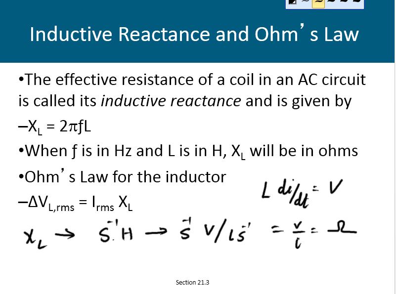
21 Inductve Reactance and Ohm s Law The efectve resistance of a coil in an AC circuit is called its inductve reactance and is given by XL = 2 ƒl When ƒ is in Hz and L is in H, XL will be in ohms Ohm s Law for the inductor ΔVL,rms = Irms XL Secton 21.3
22
23 The RLC Series Circuit The resistor, inductor, and capacitor can be combined in a circuit. The current in the circuit is the same at any tme and varies sinusoidally with tme. Secton 21.4
24 Current and Voltage Relatonships in an RLC Circuit, Graphical Summary The instantaneous voltage across the resistor is in phase with the current. The instantaneous voltage across the inductor leads the current by 90 The instantaneous voltage across the capacitor lags the current by 90 Secton 21.4
25 Phasor Diagrams To account for the diferent phases of the voltage drops, vector techniques are used. Represent the voltage across each element as a rotatng vector, called a phasor. The diagram is called a phasor diagram. Secton 21.4
26 Phasor Diagram for RLC Series Circuit The voltage across the resistor is on the +x axis since it is in phase with the current. The voltage across the inductor is on the +y since it leads the current by 90 The voltage across the capacitor is on the y axis since it lags behind the current by 90 Secton 21.4
27 Phasor Diagram, Cont. The phasors are added as vectors to account for the phase diferences in the voltages. ΔVL and ΔVC are on the same line and so the net y component is ΔVL - ΔVC Secton 21.4
28 ΔVmax From the Phasor Diagram The voltages are not in phase, so they cannot simply be added to get the voltage across the combinaton of the elements or the voltage source. is the phase angle between the current and the maximum voltage. The equatons also apply to rms values. Secton 21.4
29 Impedance of a Circuit The impedance, Z, can also be represented in a phasor diagram. Secton 21.4
30 Impedance and Ohm s Law Ohm s Law can be applied to the impedance. ΔVmax = Imax Z This can be regarded as a generalized form of Ohm s Law applied to a series AC circuit. Secton 21.4
31 Summary of Circuit Elements, Impedance and Phase Angles Secton 21.4

32 Nikola Tesla Inventor Key fgure in development of AC electricity High-voltage transformers Transport of electrical power via AC transmission lines Beat Edison s idea of DC transmission lines Secton 21.4
33 Problem Solving for RLC Circuits Calculate the inductve and capacitve reactances, XL and XC Be careful of units use F, H, Ω Use XL and XC with R to fnd Z Find the maximum current or maximum voltage drop using Ohm s Law, Vmax = Imax Z Secton 21.4
34 Problem Solving, Cont. Calculate the voltage drops across the individual elements using the appropriate form of Ohm s Law. Obtain the phase angle. Secton 21.4
35 Power in an AC Circuit No power losses are associated with pure capacitors and pure inductors in an AC circuit. In a pure capacitor, during one-half of a cycle energy is stored and during the other half the energy is returned to the circuit. In a pure inductor, the source does work against the back emf of the inductor and energy is stored in the inductor, but when the current begins to decrease in the circuit, the energy is returned to the circuit. Secton 21.5
36 1. If switch A is closed in Fig, what happens to the impedance of the circuit? (a) It increases. (b) It decreases. (c) It doesn t change 2. Suppose XL > XC in Fig. If switch A is closed, what happens to the phase angle? (a) It increases. (b) It decreases. (c) It doesn t change.2.
37 3. Suppose XL >XC in Fig. If switch A is left open and switch B is closed, what happens to the phase angle? (a) It increases. (b) It decreases. (c) It doesn t change. 4. Suppose XL >XC in Fig with both switches open, a piece of iron is slipped into the inductor. During this process, what happens to the brightness of the bulb? (a) It increases. (b) It decreases. (c) It doesn t change.
38
39 Power in an AC Circuit, Cont. The average power delivered by the generator is converted to internal energy in the resistor. Pav = IrmsΔVR = IrmsΔVrms cos cos is called the power factor of the circuit Phase shifs can be used to maximize power outputs. Secton 21.5
40 A series RLC AC circuit has resistance R = 2.50 x 10² V, inductance L = H, capacitance C = 3.50 mf, frequency f = 60.0 Hz, and maximum voltage Vmax = 1.50 x 10² V. Find (a) the impedance of the circuit, (b) the maximum current in the circuit, (c) the phase angle, and (d) the maximum voltages across the elements
41
42 Resonance in an AC Circuit Resonance occurs at the frequency, ƒo, where the current has its maximum value. To achieve maximum current, the impedance must have a minimum value. This occurs when XL = XC Then, Secton 21.6
43 Resonance, Cont. Theoretcally, if R = 0 the current would be infnite at resonance. Real circuits always have some resistance. Tuning a radio A varying capacitor changes the resonance frequency of the tuning circuit in your radio to match the staton to be received. Metal Detector The portal is an inductor, and the frequency is set to a conditon with no metal present. When metal is present, it changes the efectve inductance, which changes the current. The change in current is detected and an alarm sounds. Secton 21.6
44
45 Transformers An AC transformer consists of two coils of wire wound around a core of sof iron. The side connected to the input AC voltage source is called the primary and has N1 turns. Secton 21.7
46 Transformers, 2 The other side, called the secondary, is connected to a resistor and has N2 turns. The core is used to increase the magnetc fux and to provide a medium for the fux to pass from one coil to the other. The rate of change of the fux is the same for both coils. Secton 21.7
47 Transformers, 3 The voltages are related by When N2 > N1, the transformer is referred to as a step up transformer. When N2 < N1, the transformer is referred to as a step down transformer. Secton 21.7
48 Transformer, Final The power input into the primary equals the power output at the secondary. I1ΔV1 = I2ΔV2 If the secondary voltage is higher, the secondary current must be lower. You don t get something for nothing. This assumes an ideal transformer. In real transformers, power efciencies typically range from 90% to 99%. Secton 21.7
49 Electrical Power Transmission When transmitng electric power over long distances, it is most economical to use high voltage and low current. (conservaton of energy V1I1 = V2I2) Minimizes I2R power losses In practce, voltage is stepped up to about V at the generatng staton and stepped down to V at the distributon staton and fnally to 120 V at the customer s utlity pole. Secton 21.7

50 James Clerk Maxwell Electricity and magnetsm were originally thought to be unrelated. in 1865, James Clerk Maxwell provided a mathematcal theory that showed a close relatonship between all electric and magnetc phenomena. Secton 21.8
51 More of Maxwell s Contributons Electromagnetc theory of light Kinetc theory of gases Nature of Saturn s rings Color vision Electromagnetc feld interpretaton Led to Maxwell s Equatons Secton 21.8
52 Maxwell s Startng Points Electric feld lines originate on positve charges and terminate on negatve charges. Magnetc feld lines always form closed loops they do not begin or end anywhere. A varying magnetc feld induces an emf and hence an electric feld (Faraday s Law). Magnetc felds are generated by moving charges or currents (Ampère s Law). Secton 21.8
53 Maxwell s Predictons Maxwell used these startng points and a corresponding mathematcal framework to prove that electric and magnetc felds play symmetric roles in nature. He hypothesized that a changing electric feld would produce a magnetc feld. Maxwell calculated the speed of light to be 3x10⁸ m/s. He concluded that visible light and all other electromagnetc waves consist of fuctuatng electric and magnetc felds, with each varying feld inducing the other. Secton 21.8

54 Heinrich Rudolf Hertz First to generate and detect electromagnetc waves in a laboratory setng Showed radio waves could be refected, refracted and difracted The unit Hz is named for him. Secton 21.9
55 Hertz s Basic LC Circuit When the switch is closed, oscillatons occur in the current and in the charge on the capacitor. When the capacitor is fully charged, the total energy of the circuit is stored in the electric feld of the capacitor. At this tme, the current is zero and no energy is stored in the inductor. Secton 21.9
56 LC Circuit, Cont. As the capacitor discharges, the energy stored in the electric feld decreases. At the same tme, the current increases and the energy stored in the magnetc feld increases. When the capacitor is fully discharged, there is no energy stored in its electric feld. The current is at a maximum and all the energy is stored in the magnetc feld in the inductor. The process repeats in the opposite directon. There is a contnuous transfer of energy between the inductor and the capacitor. Secton 21.9
57 Hertz s Experimental Apparatus An inducton coil is connected to two large spheres forming a capacitor. Oscillatons are initated by short voltage pulses. The inductor and capacitor form the transmiter. Secton 21.9
58 Hertz s Experiment Several meters away from the transmiter is the receiver. This consisted of a single loop of wire connected to two spheres. It had its own efect inductance, capacitance and natural frequency of oscillaton. When the resonance frequencies of the transmiter and receiver matched, energy transfer occurred between them. Secton 21.9
59 Hertz s Conclusions Hertz hypothesized the energy transfer was in the form of waves. These are now known to be electromagnetc waves. Hertz confrmed Maxwell s theory by showing the waves existed and had all the propertes of light waves. They had diferent frequencies and wavelengths. Secton 21.9
60 Hertz s Measurement of the Speed of the Waves Hertz measured the speed of the waves from the transmiter. He used the waves to form an interference patern and calculated the wavelength. From v = f λ, v was found. v was very close to 3 x 10⁸ m/s, the known speed of light. This provided evidence in support of Maxwell s theory. Secton 21.9
61 Electromagnetc Waves Produced by an Antenna When a charged partcle undergoes an acceleraton, it must radiate energy. If currents in an ac circuit change rapidly, some energy is lost in the form of EM waves. EM waves are radiated by any circuit carrying alternatng current. An alternatng voltage applied to the wires of an antenna forces the electric charges in the antenna to oscillate. Secton 21.10
62 EM Waves by an Antenna, Cont. Two rods are connected to an ac source, charges oscillate between the rods (a). As oscillatons contnue, the rods become less charged, the feld near the charges decreases and the feld produced at t = 0 moves away from the rod (b). The charges and feld reverse (c). The oscillatons contnue (d). Secton 21.10
63 EM Waves by an Antenna, Final Because the oscillatng charges in the rod produce a current, there is also a magnetc feld generated. As the current changes, the magnetc feld spreads out from the antenna. The magnetc feld is perpendicular to the electric feld. Secton 21.10
64 Charges and Fields, Summary Statonary charges produce only electric felds. Charges in uniform moton (constant velocity) produce electric and magnetc felds. Charges that are accelerated produce electric and magnetc felds and electromagnetc waves. An acceleratng charge also radiates energy. Secton 21.10
65 Electromagnetc Waves, Summary A changing magnetc feld produces an electric feld. A changing electric feld produces a magnetc feld. These felds are in phase. At any point, both felds reach their maximum value at the same tme. Secton 21.10


66 Electromagnetc Waves are Transverse Waves The and felds are perpendicular to each other. Both felds are perpendicular to the directon of moton. Therefore, EM waves are transverse waves. Secton 21.10
67 Propertes of EM Waves Electromagnetc waves are transverse waves. Electromagnetc waves travel at the speed of light. Because EM waves travel at a speed that is precisely the speed of light, light is an electromagnetc wave. Secton 21.11
68 Propertes of EM Waves, 2 The rato of the electric feld to the magnetc feld is equal to the speed of light. Electromagnetc waves carry energy as they travel through space, and this energy can be transferred to objects placed in their path. Secton 21.11
69 Propertes of EM Waves, 3 Energy carried by EM waves is shared equally by the electric and magnetc felds. Intensity (I) is average power per unit area. Secton 21.11
70 Propertes of EM Waves, Final Electromagnetc waves transport linear momentum as well as energy. For complete absorpton of energy U, p=u/c For complete refecton of energy U, p=(2u)/c Radiaton pressures can be determined experimentally. Secton 21.11

71 Determining Radiaton Pressure This is an apparatus for measuring radiaton pressure. In practce, the system is contained in a vacuum. The pressure is determined by the angle at which equilibrium occurs. Secton 21.11
72 Propertes of EM Waves, Summary EM waves travel at the speed of light. EM waves are transverse waves because the electric and magnetc felds are perpendicular to the directon of propagaton of the wave and to each other. The rato of the electric feld to the magnetc feld in an EM wave equals the speed of light. EM waves carry both energy and momentum, which can be delivered to a surface. Secton 21.11
73 The Spectrum of EM Waves Forms of electromagnetc waves exist that are distnguished by their frequencies and wavelengths. c = ƒλ Wavelengths for visible light range from 400 nm to 700 nm. There is no sharp division between one kind of EM wave and the next. Secton 21.12

74 The EM Spectrum Note the overlap between types of waves. Visible light is a small porton of the spectrum. Types are distnguished by frequency or wavelength. Secton 21.12
75 Notes on The EM Spectrum Radio Waves Used in radio and television communicaton systems Microwaves Wavelengths from about 1 mm to 30 cm Well suited for radar systems Microwave ovens are an applicaton Secton 21.12
76 Notes on the EM Spectrum, 2 Infrared waves Incorrectly called heat waves Produced by hot objects and molecules Wavelengths range from about 1 mm to 700 nm Readily absorbed by most materials Visible light Part of the spectrum detected by the human eye Wavelengths range from 400 nm to 700 nm Most sensitve at about 560 nm (yellow-green) Secton 21.12
77 Notes on the EM Spectrum, 3 Ultraviolet light Covers about 400 nm to 0.6 nm The Sun is an important source of uv light. Most uv light from the sun is absorbed in the stratosphere by ozone. X-rays Wavelengths range from about 10 nm to 10-4 nm Most common source is acceleraton of high-energy electrons striking a metal target Used as a diagnostc tool in medicine Secton 21.12
78 Notes on the EM Spectrum, Final Gamma rays Wavelengths from about m to m Emited by radioactve nuclei Highly penetratng and cause serious damage when absorbed by living tssue Looking at objects in diferent portons of the spectrum can produce diferent informaton. Secton 21.12

79 Crab Nebula in Various Wavelengths Secton 21.12
80 Doppler Efect and EM Waves A Doppler Efect occurs for EM waves, but difers from that of sound waves. For sound waves, moton relatve to a medium is most important. For light waves, the medium plays no role since the light waves do not require a medium for propagaton. The speed of sound depends on its frame of reference. The speed of EM waves is the same in all coordinate systems that are at rest or moving with a constant velocity with respect to each other. Secton 21.13
81 Doppler Equaton for EM Waves The Doppler efect for EM waves fo is the observed frequency. fs is the frequency emited by the source. u is the relatve speed of the source and the observer. The equaton is valid only when u is much smaller than c. Secton 21.13
82 Doppler Equaton, Cont. The positve sign is used when the object and source are moving toward each other. The negatve sign is used when the object and source are moving away from each other. Astronomers refer to a red shif when objects are moving away from the earth since the wavelengths are shifed toward the red end of the spectrum.
Chapter 21. Alternating Current Circuits and Electromagnetic Waves
 Chapter 21 Alternating Current Circuits and Electromagnetic Waves AC Circuit An AC circuit consists of a combination of circuit elements and an AC generator or source The output of an AC generator is sinusoidal
General Physics (PHY 2140)
") General Physics (PHY 2140) Lecture 11 Electricity and Magnetism AC circuits and EM waves Resonance in a Series RLC circuit Transformers Maxwell, Hertz and EM waves Electromagnetic Waves 6/18/2007 http://www.physics.wayne.edu/~alan/2140website/main.htm
General Physics (PHY 2140) Lecture 11 Electricity and Magnetism AC circuits and EM waves Resonance in a Series RLC circuit Transformers Maxwell, Hertz and EM waves Electromagnetic Waves 6/18/2007 http://www.physics.wayne.edu/~alan/2140website/main.htm
AC Circuit. What is alternating current? What is an AC circuit?
 Chapter 21 Alternating Current Circuits and Electromagnetic Waves 1. Alternating Current 2. Resistor in an AC circuit 3. Capacitor in an AC circuit 4. Inductor in an AC circuit 5. RLC series circuit 6.
Chapter 25. Electromagnetic Waves
 Chapter 25 Electromagnetic Waves EXAM # 3 Nov. 20-21 Chapter 23 Chapter 25 Powerpoint Nov. 4 Problems from previous exams Physics in Perspective (pg. 836 837) Chapter 25 Electromagnetic Waves Units of
Chapter 33. Alternating Current Circuits
 Chapter 33 Alternating Current Circuits Alternating Current Circuits Electrical appliances in the house use alternating current (AC) circuits. If an AC source applies an alternating voltage to a series
An induced emf is the negative of a changing magnetic field. Similarly, a self-induced emf would be found by
 This is a study guide for Exam 4. You are expected to understand and be able to answer mathematical questions on the following topics. Chapter 32 Self-Induction and Induction While a battery creates an
ELECTROMAGNETIC INDUCTION AND ALTERNATING CURRENT (Assignment)
") ELECTROMAGNETIC INDUCTION AND ALTERNATING CURRENT (Assignment) 1. In an A.C. circuit A ; the current leads the voltage by 30 0 and in circuit B, the current lags behind the voltage by 30 0. What is the
ELECTROMAGNETIC INDUCTION AND ALTERNATING CURRENT (Assignment) 1. In an A.C. circuit A ; the current leads the voltage by 30 0 and in circuit B, the current lags behind the voltage by 30 0. What is the
Physics for Scientists & Engineers 2 2 = 1 LC. Review ( ) Review (2) Review (3) e! Rt. cos "t + # ( ) q = q max. Spring Semester 2005 Lecture 30 U E
 Review (2) Review (3) e! Rt. cos t + # ( ) q = q max. Spring Semester 2005 Lecture 30 U E") Review hysics for Scientists & Engineers Spring Semester 005 Lecture 30! If we have a single loop RLC circuit, the charge in the circuit as a function of time is given by! Where q = q max e! Rt L cos "t
Review hysics for Scientists & Engineers Spring Semester 005 Lecture 30! If we have a single loop RLC circuit, the charge in the circuit as a function of time is given by! Where q = q max e! Rt L cos "t
Alternating Current. Slide 1 / 69. Slide 2 / 69. Slide 3 / 69. Topics to be covered. Sources of Alternating EMF. Sources of alternating EMF
 Slide 1 / 69 lternating urrent Sources of alternating EMF Transformers ircuits and Impedance Topics to be covered Slide 2 / 69 LR Series ircuits Resonance in ircuit Oscillations Sources of lternating EMF
Alternating Current. Slide 2 / 69. Slide 1 / 69. Slide 3 / 69. Slide 4 / 69. Slide 6 / 69. Slide 5 / 69. Topics to be covered
 Slide 1 / 69 lternating urrent Sources of alternating EMF ircuits and Impedance Slide 2 / 69 Topics to be covered LR Series ircuits Resonance in ircuit Oscillations Slide 3 / 69 Sources of lternating EMF
Chapter 30 Inductance, Electromagnetic. Copyright 2009 Pearson Education, Inc.
 Chapter 30 Inductance, Electromagnetic Oscillations, and AC Circuits 30-7 AC Circuits with AC Source Resistors, capacitors, and inductors have different phase relationships between current and voltage
Chapter 33. Alternating Current Circuits
 Chapter 33 Alternating Current Circuits C HAP T E O UTLI N E 33 1 AC Sources 33 2 esistors in an AC Circuit 33 3 Inductors in an AC Circuit 33 4 Capacitors in an AC Circuit 33 5 The L Series Circuit 33
15. the power factor of an a.c circuit is.5 what will be the phase difference between voltage and current in this
 1 1. In a series LCR circuit the voltage across inductor, a capacitor and a resistor are 30 V, 30 V and 60 V respectively. What is the phase difference between applied voltage and current in the circuit?
Chapter 6: Alternating Current. An alternating current is an current that reverses its direction at regular intervals.
 Chapter 6: Alternating Current An alternating current is an current that reverses its direction at regular intervals. Overview Alternating Current Phasor Diagram Sinusoidal Waveform A.C. Through a Resistor
Chapter 11. Alternating Current
 Unit-2 ECE131 BEEE Chapter 11 Alternating Current Objectives After completing this chapter, you will be able to: Describe how an AC voltage is produced with an AC generator (alternator) Define alternation,
Electromagnetic Oscillations and Currents. March 23, 2014 Chapter 30 1
 Electromagnetic Oscillations and Currents March 23, 2014 Chapter 30 1 Driven LC Circuit! The voltage V can be thought of as the projection of the vertical axis of the phasor V m representing the time-varying
RC circuit. Recall the series RC circuit.
 RC circuit Recall the series RC circuit. If C is discharged and then a constant voltage V is suddenly applied, the charge on, and voltage across, C is initially zero. The charge ultimately reaches the
Look over Chapter 31 sections 1-4, 6, 8, 9, 10, 11 Examples 1-8. Look over Chapter 21 sections Examples PHYS 2212 PHYS 1112
 PHYS 2212 Look over Chapter 31 sections 1-4, 6, 8, 9, 10, 11 Examples 1-8 PHYS 1112 Look over Chapter 21 sections 11-14 Examples 16-18 Good Things To Know 1) How AC generators work. 2) How to find the
PHYSICS WORKSHEET CLASS : XII. Topic: Alternating current
 PHYSICS WORKSHEET CLASS : XII Topic: Alternating current 1. What is mean by root mean square value of alternating current? 2. Distinguish between the terms effective value and peak value of an alternating
CHAPTER 6: ALTERNATING CURRENT
 CHAPTER 6: ALTERNATING CURRENT PSPM II 2005/2006 NO. 12(C) 12. (c) An ac generator with rms voltage 240 V is connected to a RC circuit. The rms current in the circuit is 1.5 A and leads the voltage by
Lecture Notes (Electric & Magnetic Fields in Space)
") James C. Maxwell: Lecture Notes (Electric & Magnetic Fields in Space) - Maxwell (1831-1879) was a Scottish physicist who is generally regarded as the most profound and productive physicist between the
James C. Maxwell: Lecture Notes (Electric & Magnetic Fields in Space) - Maxwell (1831-1879) was a Scottish physicist who is generally regarded as the most profound and productive physicist between the
Exam 3 Solutions. ! r, the ratio is ( N ) ( ) ( )( ) 2. PHY2054 Spring Prof. Pradeep Kumar Prof. Paul Avery Prof. Yoonseok Lee Mar.
 ( ) ( )( ) 2. PHY2054 Spring Prof. Pradeep Kumar Prof. Paul Avery Prof. Yoonseok Lee Mar.") PHY054 Spring 009 Prof. Pradeep Kumar Prof. Paul Avery Prof. Yoonseok Lee Mar. 7, 009 Exam 3 Solutions 1. Two coils (A and B) made out of the same wire are in a uniform magnetic field with the coil axes
PHY054 Spring 009 Prof. Pradeep Kumar Prof. Paul Avery Prof. Yoonseok Lee Mar. 7, 009 Exam 3 Solutions 1. Two coils (A and B) made out of the same wire are in a uniform magnetic field with the coil axes
INTRODUCTION. 5. Electromagnetic Waves
 INTRODUCTION An electric current produces a magnetic field, and a changing magnetic field produces an electric field Because of such a connection, we refer to the phenomena of electricity and magnetism
Chapter 24. Alternating Current Circuits
 Chapter 24 Alternating Current Circuits Objective of Lecture Generators and Motors Inductance RL Circuits (resistance and inductance) Transformers AC REMINDER: WORK ON THE EXAMPLES Read physics in perspective
Chapter 31. Alternating Current. PowerPoint Lectures for University Physics, 14th Edition Hugh D. Young and Roger A. Freedman Lectures by Jason Harlow
 Chapter 31 Alternating Current PowerPoint Lectures for University Physics, 14th Edition Hugh D. Young and Roger A. Freedman Lectures by Jason Harlow Learning Goals for Chapter 31 Looking forward at How
Alternating current circuits- Series RLC circuits
 FISI30 Física Universitaria II Professor J.. ersosimo hapter 8 Alternating current circuits- Series circuits 8- Introduction A loop rotated in a magnetic field produces a sinusoidal voltage and current.
ELECTROMAGNETIC WAVES MARKS WEIGHTAGE 3 marks
 ELECTROMAGNETIC WAVES MARKS WEIGHTAGE 3 marks QUICK REVISION (Important Concepts & Formulas) Electromagnetic radiation is the radiation in which associated electric and magnetic field oscillations are
AP Physics C. Alternating Current. Chapter Problems. Sources of Alternating EMF
 AP Physics C Alternating Current Chapter Problems Sources of Alternating EMF 1. A 10 cm diameter loop of wire is oriented perpendicular to a 2.5 T magnetic field. What is the magnetic flux through the
Lecture Outline Chapter 24. Physics, 4 th Edition James S. Walker. Copyright 2010 Pearson Education, Inc.
 Lecture Outline Chapter 24 Physics, 4 th Edition James S. Walker Chapter 24 Alternating-Current Circuits Units of Chapter 24 Alternating Voltages and Currents Capacitors in AC Circuits RC Circuits Inductors
Physics 102: Lecture 14 Electromagnetic Waves
 Physics 102: Lecture 14 Electromagnetic Waves Physics 102: Lecture 14, Slide 1 Review: Phasors & Resonance At resonance Z is minimum (=R) I max is maximum (=V gen,max /R) V gen is in phase with I X L =
AC Circuits INTRODUCTION DISCUSSION OF PRINCIPLES. Resistance in an AC Circuit
 AC Circuits INTRODUCTION The study of alternating current 1 (AC) in physics is very important as it has practical applications in our daily lives. As the name implies, the current and voltage change directions
Exercise 9: inductor-resistor-capacitor (LRC) circuits
 circuits") Exercise 9: inductor-resistor-capacitor (LRC) circuits Purpose: to study the relationship of the phase and resonance on capacitor and inductor reactance in a circuit driven by an AC signal. Introduction
Exercise 9: inductor-resistor-capacitor (LRC) circuits Purpose: to study the relationship of the phase and resonance on capacitor and inductor reactance in a circuit driven by an AC signal. Introduction
E) all of the above E) 1.9 T
 all of the above E) 1.9 T") 1. The figure shows a uniform magnetic field that is normal to the plane of a conducting loop, which has a resistance R. Which one of the following changes will cause an induced current to flow through
1. The figure shows a uniform magnetic field that is normal to the plane of a conducting loop, which has a resistance R. Which one of the following changes will cause an induced current to flow through
Physics 1442 and 1444 Questions and problems Only
 Physics 1442 and 1444 Questions and problems Only U15Q1 To measure current using a digital multimeter the probes of the meter would be placed the component. ) in parallel with ) in series with C) adjacent
Series and Parallel Resonant Circuits
 Series and Parallel Resonant Circuits Aim: To obtain the characteristics of series and parallel resonant circuits. Apparatus required: Decade resistance box, Decade inductance box, Decade capacitance box
Turn off all electronic devices
 Radio 1 Radio 2 Observations about Radio Radio It can transmit sound long distances wirelessly It involve antennas It apparently involves electricity and magnetism Its reception depends on antenna positioning
No Brain Too Small PHYSICS
 ELECTRICITY: AC QUESTIONS No Brain Too Small PHYSICS MEASURING IRON IN SAND (2016;3) Vivienne wants to measure the amount of iron in ironsand mixtures collected from different beaches. The diagram below
Physics Class 12 th NCERT Solutions
 Chapter.7 Alternating Current Class XII Subject Physics 7.1. A 100 Ω resistor is connected to a 220 V, 50 Hz ac supply. a) What is the rms value of current in the circuit? b) What is the net power consumed
z z" z v 2 ft = 2k ft. 328 Concepts of Physics The energy dissipated in 1000 s = P * 1000 s
 38 Concepts of Physics. A series AC circuit contains an inductor ( mh), a capacitor ( (JF), a resistor ( ft) and an AC source of V, Hz. Find the energy dissipated in the circuit in s. Solution : The time
LECTURE 19. Alternating Current Generators (DEMO)
") ETURE 9 A Generators A ircuits Start by considering simple circuits with one element (R,, or ) in addition to the driving emf. It will lead to Oscillations and Driven R circuits Alternating urrent Generators
ETURE 9 A Generators A ircuits Start by considering simple circuits with one element (R,, or ) in addition to the driving emf. It will lead to Oscillations and Driven R circuits Alternating urrent Generators
Ac fundamentals and AC CIRCUITS. Q1. Explain and derive an expression for generation of AC quantity.
 Ac fundamentals and AC CIRCUITS Q1. Explain and derive an expression for generation of AC quantity. According to Faradays law of electromagnetic induction when a conductor is moving within a magnetic field,
Announcements. EM Induction. Faraday s Law 4/24/15. Why is current induced? EM Induction: Current is Induced
 Announcements Today: Induction & transformers Wednesday: Finish transformers, start light Reading: review Fig. 26.3 and Fig. 26.8 Recall: N/S poles (opposites attract) Moving electrical charges produce
Properties of Waves, Magnetism, & Electricity Unit 4 Summative Assessment
 1. When a sound wave travels through a medium, what is being transmitted in the direction of the movement of the wave? density mass energy velocity 2. An iron rod changes colors when heated in a hot flame.
In an unmagnetized piece of iron, the atoms are arranged in domains. In each domain the atoms are aligned, but the domains themselves are random.
 4/7 Properties of the Magnetic Force 1. Perpendicular to the field and velocity. 2. If the velocity and field are parallel, the force is zero. 3. Roughly (field and vel perp), the force is the product
Chapter 6: Alternating Current
 hapter 6: Alternating urrent 6. Alternating urrent.o 6.. Define alternating current (A) An alternating current (A) is the electrical current which varies periodically with time in direction and magnitude.
1. If the flux associated with a coil varies at the rate of 1 weber/min,the induced emf is
 1. f the flux associated with a coil varies at the rate of 1 weber/min,the induced emf is 1 1. 1V 2. V 60 3. 60V 4. Zero 2. Lenz s law is the consequence of the law of conservation of 1. Charge 2. Mass
Lecture 38: MON 24 NOV Ch.33 Electromagnetic Waves
 Physics 2113 Jonathan Dowling Heinrich Hertz (1857 1894) Lecture 38: MON 24 NOV Ch.33 Electromagnetic Waves Maxwell Equations in Empty Space: E da = 0 S B da = 0 S C C B ds = µ ε 0 0 E ds = d dt d dt S
Physics 1C. Lecture 24A. Finish Chapter 27: X-ray diffraction Start Chapter 24: EM waves. Average Quiz score = 6.8 out of 10.
 Physics 1C Lecture 24A Finish Chapter 27: X-ray diffraction Start Chapter 24: EM waves Average Quiz score = 6.8 out of 10 This is a B- Diffraction of X-rays by Crystals! X-rays are electromagnetic radiation
Class XII Chapter 7 Alternating Current Physics
 Question 7.1: A 100 Ω resistor is connected to a 220 V, 50 Hz ac supply. (a) What is the rms value of current in the circuit? (b) What is the net power consumed over a full cycle? Resistance of the resistor,
Bakiss Hiyana binti Abu Bakar JKE, POLISAS BHAB
 1 Bakiss Hiyana binti Abu Bakar JKE, POLISAS 1. Explain AC circuit concept and their analysis using AC circuit law. 2. Apply the knowledge of AC circuit in solving problem related to AC electrical circuit.
Experiment 7: Undriven & Driven RLC Circuits
 MASSACHUSETTS INSTITUTE OF TECHNOLOGY Department of Physics 8.02 Spring 2006 OBJECTIVES Experiment 7: Undriven & Driven RLC Circuits 1. To explore the time dependent behavior of RLC Circuits, both driven
Alternating Current Circuits and Electromagnetic Waves
 hapter Alternating urrent ircuits and Electromagnetic Wes Quick Quizzes. (a, (c. The erage power is proportional to the current which is non-zero even though the erage current is zero. (a is only valid
Intermediate Physics PHYS102
 Intermediate Physics PHYS102 Dr Richard H. Cyburt Assistant Professor of Physics My office: 402c in the Science Building My phone: (304) 384-6006 My email: rcyburt@concord.edu My webpage: www.concord.edu/rcyburt
California State University, Bakersfield. Signals and Systems. Luis Medina,
 Luis Medina, Department of Electrical and Computer Engineering, California State University, Bakersfield Lecture 9 (Intro, History and Background) July 29 th, 2013 1 Electric Fields An electric field surrounds
QUESTION BANK ETE (17331) CM/IF. Chapter1: DC Circuits
 CM/IF. Chapter1: DC Circuits") QUESTION BANK ETE (17331) CM/IF Chapter1: DC Circuits Q1. State & explain Ohms law. Also explain concept of series & parallel circuit with the help of diagram. 3M Q2. Find the value of resistor in fig.
QUESTION BANK ETE (17331) CM/IF Chapter1: DC Circuits Q1. State & explain Ohms law. Also explain concept of series & parallel circuit with the help of diagram. 3M Q2. Find the value of resistor in fig.
Chapter 25 Alternating Currents
 Chapter 25 Alternating Currents GOALS When you have mastered the contents of this chapter, you will be able to achieve the following goals: Definitions Define each of the following terms and use it in
22-1 (SJP, Phys 2020, Fa '01)
") 22-1 (SJP, Phys 2020, Fa '01) Ch. 22: Electromagnetic waves. We ve seen some of the ideas/discoveries of Ampere, Faraday, and others. So far, E & B seem different but somehow related. In what is perhaps
22-1 (SJP, Phys 2020, Fa '01) Ch. 22: Electromagnetic waves. We ve seen some of the ideas/discoveries of Ampere, Faraday, and others. So far, E & B seem different but somehow related. In what is perhaps
Worksheet for Exploration 31.1: Amplitude, Frequency and Phase Shift
 Worksheet for Exploration 31.1: Amplitude, Frequency and Phase Shift We characterize the voltage (or current) in AC circuits in terms of the amplitude, frequency (period) and phase. The sinusoidal voltage
ELECTROMAGNETIC WAVES HERTZ S EXPERIMENTS & OBSERVATIONS
 VISUAL PHYSICS ONLINE MODULE 7 NATURE OF LIGHT ELECTROMAGNETIC WAVES HERTZ S EXPERIMENTS & OBSERVATIONS PRODUCTION & RECEPTION OF RADIO WAVES Heinrich Rudolf Hertz (1857 1894) was a German physicist who
(A) 2f (B) 2 f (C) f ( D) 2 (E) 2
 2f (B) 2 f (C) f ( D) 2 (E) 2") 1. A small vibrating object S moves across the surface of a ripple tank producing the wave fronts shown above. The wave fronts move with speed v. The object is traveling in what direction and with what
1. A small vibrating object S moves across the surface of a ripple tank producing the wave fronts shown above. The wave fronts move with speed v. The object is traveling in what direction and with what
Wave Behavior and The electromagnetic Spectrum
 Wave Behavior and The electromagnetic Spectrum What is Light? We call light Electromagnetic Radiation. Or EM for short It s composed of both an electrical wave and a magnetic wave. Wave or particle? Just
Chapter 16 Light Waves and Color
 Chapter 16 Light Waves and Color Lecture PowerPoint Copyright The McGraw-Hill Companies, Inc. Permission required for reproduction or display. What causes color? What causes reflection? What causes color?
BAKISS HIYANA BT ABU BAKAR JKE,POLISAS
 BAKISS HIYANA BT ABU BAKAR JKE,POLISAS 1 1. Explain AC circuit concept and their analysis using AC circuit law. 2. Apply the knowledge of AC circuit in solving problem related to AC electrical circuit.
Electricity & Optics
 Physics 24100 Electricity & Optics Lecture 19 Chapter 29 sec. 1,2,5 Fall 2017 Semester Professor Koltick Series and Parallel R and L Resistors and inductors in series: R series = R 1 + R 2 L series = L
LCR CIRCUITS Institute of Lifelong Learning, University of Delhi
 L UTS nstitute of Lifelong Learning, University of Delhi L UTS PHYSS (LAB MANUAL) nstitute of Lifelong Learning, University of Delhi PHYSS (LAB MANUAL) L UTS ntroduction ircuits containing an inductor
James Clerk Maxwell. Electric and Magnetic Fields
 L 30 Electricity and Magnetism [7] Electromagnetic Waves Faraday laid the groundwork with his discovery of electromagnetic induction Maxwell added the last piece of the puzzle Hertz made the experimental
AC Circuits. Nikola Tesla
 AC Circuits Nikola Tesla 1856-1943 Mar 26, 2012 Alternating Current Circuits Electrical appliances in the house use alternating current (AC) circuits. If an AC source applies an alternating voltage of
Chapter 31 Alternating Current
 Chapter 31 Alternating Current In this chapter we will learn how resistors, inductors, and capacitors behave in circuits with sinusoidally vary voltages and currents. We will define the relationship between
( ). (9.3) 9. EXPERIMENT E9: THE RLC CIRCUIT OBJECTIVES
. (9.3) 9. EXPERIMENT E9: THE RLC CIRCUIT OBJECTIVES") 9. EXPERIMENT E9: THE RLC CIRCUIT OBJECTIVES In this experiment, you will measure the electric current, voltage, reactance, impedance, and understand the resonance phenomenon in an alternating-current
9. EXPERIMENT E9: THE RLC CIRCUIT OBJECTIVES In this experiment, you will measure the electric current, voltage, reactance, impedance, and understand the resonance phenomenon in an alternating-current
Chapter 28 Alternating Current Circuits
 History teaches us that the searching spirit of man required thousands of years for the discovery of the fundamental principles of the sciences, on which the superstructure was then raised in a comparatively
Wave & Electromagnetic Spectrum Notes
 Wave & Electromagnetic Spectrum Notes December 17, 2011 I.) Properties of Waves A) Wave: A periodic disturbance in a solid, liquid or gas as energy is transmitted through a medium ( Waves carry energy
Electrical Theory. Power Principles and Phase Angle. PJM State & Member Training Dept. PJM /22/2018
 Electrical Theory Power Principles and Phase Angle PJM State & Member Training Dept. PJM 2018 Objectives At the end of this presentation the learner will be able to: Identify the characteristics of Sine
ECE 2006 University of Minnesota Duluth Lab 11. AC Circuits
 1. Objective AC Circuits In this lab, the student will study sinusoidal voltages and currents in order to understand frequency, period, effective value, instantaneous power and average power. Also, the
A.C. Circuits -- Conceptual Solutions
 A.C. Circuits -- Conceptual Solutions 1.) Charge carriers in a DC circuit move in one direction only. What do charge carriers do in an AC circuit? Solution: The voltage difference between the terminals
KINGS COLLEGE OF ENGINEERING DEPARTMENT OF ELECTRICAL AND ELECTRONICS ENGINEERING QUESTION BANK UNIT I BASIC CIRCUITS ANALYSIS PART A (2-MARKS)
") KINGS COLLEGE OF ENGINEERING DEPARTMENT OF ELECTRICAL AND ELECTRONICS ENGINEERING QUESTION BANK YEAR / SEM : I / II SUBJECT CODE & NAME : EE 1151 CIRCUIT THEORY UNIT I BASIC CIRCUITS ANALYSIS PART A (2-MARKS)
KINGS COLLEGE OF ENGINEERING DEPARTMENT OF ELECTRICAL AND ELECTRONICS ENGINEERING QUESTION BANK YEAR / SEM : I / II SUBJECT CODE & NAME : EE 1151 CIRCUIT THEORY UNIT I BASIC CIRCUITS ANALYSIS PART A (2-MARKS)
Lecture PowerPoints. Chapter 22 Physics: Principles with Applications, 7 th edition Giancoli
 Lecture PowerPoints Chapter 22 Physics: Principles with Applications, 7 th edition Giancoli This work is protected by United States copyright laws and is provided solely for the use of instructors in teaching
Lesson 24 Electromagnetic Waves
 Physics 30 Lesson 24 Electromagnetic Waves On April 11, 1846, Michael Faraday was scheduled to introduce Sir Charles Wheatstone at a meeting of the Royal Society of London. Unfortunately, Wheatstone had
Antenna? What s That? Chet Thayer WA3I
 Antenna? What s That? Chet Thayer WA3I Space: The Final Frontier Empty Space (-Time) Four dimensional region that holds everything Is Permeable : It requires energy to set up a magnetic field within it.
12/6/2011. Electromagnetic Induction. Electromagnetic Induction and Electromagnetic Waves. Checking Understanding. Magnetic Flux. Lenz s Law.
 Electromagnetic Induction and Electromagnetic Waves Topics: Electromagnetic induction Lenz s law Faraday s law The nature of electromagnetic waves The spectrum of electromagnetic waves Electromagnetic
SIDDHARTH GROUP OF INSTITUTIONS :: PUTTUR (AUTONOMOUS) Siddharth Nagar, Narayanavanam Road QUESTION BANK (DESCRIPTIVE) UNIT I INTRODUCTION
 Siddharth Nagar, Narayanavanam Road QUESTION BANK (DESCRIPTIVE) UNIT I INTRODUCTION") SIDDHARTH GROUP OF INSTITUTIONS :: PUTTUR (AUTONOMOUS) Siddharth Nagar, Narayanavanam Road 517583 QUESTION BANK (DESCRIPTIVE) Subject with Code : Electrical Circuits(16EE201) Year & Sem: I-B.Tech & II-Sem
SIDDHARTH GROUP OF INSTITUTIONS :: PUTTUR (AUTONOMOUS) Siddharth Nagar, Narayanavanam Road 517583 QUESTION BANK (DESCRIPTIVE) Subject with Code : Electrical Circuits(16EE201) Year & Sem: I-B.Tech & II-Sem
Alternating Current Page 1 30
 Alternating Current 26201 11 Page 1 30 Calculate the peak and effective voltage of current values for AC Calculate the phase relationship between two AC waveforms Describe the voltage and current phase
Topic 4: Waves 4.2 Traveling waves
 Crests and troughs Compare the waves traveling through the mediums of rope and spring. CREST TROUGH TRANSVERSE WAVE COMPRESSION RAREFACTION LONGITUDINAL WAVE Wave speed and frequency The speed at which
EXPERIMENT FREQUENCY RESPONSE OF AC CIRCUITS. Structure. 8.1 Introduction Objectives
 EXPERIMENT 8 FREQUENCY RESPONSE OF AC CIRCUITS Frequency Response of AC Circuits Structure 81 Introduction Objectives 8 Characteristics of a Series-LCR Circuit 83 Frequency Responses of a Resistor, an
Physics Unit 5 Waves Light & Sound
 Physics Unit 5 Waves Light & Sound Wave A rhythmic disturbance that transfers energy through matter and/or a vacuum Material a wave travels through is called the medium 2 types of waves: 1. Transverse
Chapter Moving Charges and Magnetism
 100 Chapter Moving Charges and Magnetism 1. The power factor of an AC circuit having resistance (R) and inductance (L) connected in series and an angular velocity ω is [2013] 2. [2002] zero RvB vbl/r vbl
Unit 15 Electromagnetic Waves
 Unit 5 Electromagnetic Waves 97 SUMMRY 9 99 MCQ For the answer of the following questions choose the correct alternative from among the given ones. () Who produced the electromagnetic waves first? Marconi
Note 2 Electromagnetic waves N2/EMWAVES/PHY/XII/CHS2012
 ELECTROMAGNETIC SPECTRUM Electromagnetic waves include visible light waves, X-rays, gamma rays, radio waves, microwaves, ultraviolet and infrared waves. The classification of em waves according to frequency
Solution: All electromagnetic waves in vacuum, regardless of their wavelength or frequency, travel at the speed of light, c.
 1. Two electromagnetic waves travel through empty space. Wave A as a wavelength of 700 nm (red light), while Wave B has a wavelength of 400 nm (blue light). Which statement is true? A) Wave A travels faster
PHYSICS - CLUTCH CH 29: ALTERNATING CURRENT.
 !! www.clutchprep.com CONCEPT: ALTERNATING VOLTAGES AND CURRENTS BEFORE, we only considered DIRECT CURRENTS, currents that only move in - NOW we consider ALTERNATING CURRENTS, currents that move in Alternating
not to be republished NCERT ALTERNATING CURRENT Chapter Seven MCQ 1
 hapter Seven ALTERNATING URRENT MQ 1 7.1 If the rms current in a 50 Hz ac circuit is 5 A, the value of the current 1/300 seconds after its value becomes zero is (a) 5 2 A (b) 5 3/2 A (c) 5/6 A (d) 5/ 2
Chapter 23 Electromagnetic Waves Lecture 14
 Chapter 23 Electromagnetic Waves Lecture 14 23.1 The Discovery of Electromagnetic Waves 23.2 Properties of Electromagnetic Waves 23.3 Electromagnetic Waves Carry Energy and Momentum 23.4 Types of Electromagnetic
AC Sources and Phasors
 AC Sources and Phasors Circuits powered by a sinusoidal emf are called AC circuits, where AC stands for alternating current. Steady-current circuits are called DC circuits, for direct current. The instantaneous
Waves Mechanical vs. Electromagnetic Mechanical Electromagnetic Transverse vs. Longitudinal Behavior of Light
 PSC1341 Chapter 4 Waves Chapter 4: Wave Motion A.. The Behavior of Light B. The E-M spectrum C. Equations D. Reflection, Refraction, Lenses and Diffraction E. Constructive Interference, Destructive Interference
DC and AC Circuits. Objective. Theory. 1. Direct Current (DC) R-C Circuit
 R-C Circuit") [International Campus Lab] Objective Determine the behavior of resistors, capacitors, and inductors in DC and AC circuits. Theory ----------------------------- Reference -------------------------- Young
[International Campus Lab] Objective Determine the behavior of resistors, capacitors, and inductors in DC and AC circuits. Theory ----------------------------- Reference -------------------------- Young
CHAPTER 2. Basic Concepts, Three-Phase Review, and Per Unit
 CHAPTER 2 Basic Concepts, Three-Phase Review, and Per Unit 1 AC power versus DC power DC system: - Power delivered to the load does not fluctuate. - If the transmission line is long power is lost in the
ALTERNATING CURRENT CIRCUITS
 CHAPTE 23 ALTENATNG CUENT CCUTS CONCEPTUAL QUESTONS 1. EASONNG AND SOLUTON A light bulb and a parallel plate capacitor (including a dielectric material between the plates) are connected in series to the
ELECTROMAGNETIC WAVES AND THE EM SPECTRUM MR. BANKS 8 TH GRADE SCIENCE
 ELECTROMAGNETIC WAVES AND THE EM SPECTRUM MR. BANKS 8 TH GRADE SCIENCE ELECTROMAGNETIC WAVES Do not need matter to transfer energy. Made by vibrating electric charges. When an electric charge vibrates,
WAVES & EM SPECTRUM. Chapters 10 & 15
 WAVES & EM SPECTRUM Chapters 10 & 15 What s a wave? repeating disturbance transfers energy through matter or space Oscillation back & forth movement carries energy w/o transporting matter can travel through
Sirindhorn International Institute of Technology Thammasat University
 Sirindhorn International Institute of Technology Thammasat University School of Information, Computer and Communication Technology COURSE : ECS 34 Basic Electrical Engineering Lab INSTRUCTOR : Dr. Prapun
INTRODUCTION TO AC FILTERS AND RESONANCE
 AC Filters & Resonance 167 Name Date Partners INTRODUCTION TO AC FILTERS AND RESONANCE OBJECTIVES To understand the design of capacitive and inductive filters To understand resonance in circuits driven