S. Eswar Prasad, Adjunct Professor, Department of Mechanical & Industrial Engineering, Chairman, Piemades Inc, Piemades, Inc.
|
|
|
- Mariah Goodman
- 6 years ago
- Views:
Transcription
1 Lecture 1: Introduction to Smart Materials and Systems Lecture 2: Sensor technologies for smart systems and their evaluation criteria. Lecture 3: Actuator technologies for smart systems and their evaluation criteria. Lecture 4: Piezoelectric Materials and their Applications. Lecture 5: Control System Technologies. Lecture 6: Smart System Applications. S. Eswar Prasad, Adjunct Professor, Department of Mechanical & Industrial Engineering, Chairman, Piemades Inc, Piemades, Inc. 1
2 Control Technologies for Smart Systems S. Eswar Prasad, Adjunct Professor, Department of Mechanical & Industrial Engineering, Chairman, Piemades Inc, Piemades, Inc. 2
3 Control Technologies for Smart Systems Control Systems Overview Open loop and closed loop systems Control System Characteristics Steady State, Transient Response and Stability Controller Operation Proportional, Compensated Digital Control Systems Control algorithms, implementation, hardware Control System Design 3 3
4 Control Systems Overview Deals with influencing the behaviour of dynamic systems Interdisciplinary field, which originated in engineering and mathematics, and evolved into use by the social sciences, like psychology, sociology, criminology and in financial systems. Control systems have four basic functions; Measure, Compare, Compute, and Correct. These four functions are completed by three elements; Sensors, Actuators, Control System. In a smart system, these three elements are typically contained in one unit. 4
5 Control Systems Overview Definition of a Smart System 5
6 Control Systems Overview Historical Feedback control (Bode,1945) Theory of Stochastic Processes (Weiner, 1930) Root Locus Theory (Evans, 1948) Modern Control (1950s, Kalman, Bellman, Pontryagin) Root locus theory remains an important technique today. Suitable for design and stability analysis. Root locus analysis is a graphical method for examining how the roots of a system change with variation of a certain system parameter, commonly the gain of a feedback system. This is a technique used in the field of control systems developed by Walter R. Evans. 6
7 Control Systems Overview Root locus approach Assumption The definition of the damping ratio and natural frequency presumes that the overall feedback system is well approximated by a second order system, that is, the system has a dominant pair of poles. Uses Determine the stability of the system Design for the damping ratio and natural frequency of a feedback system. Lag, lead, PI, PD and PID controllers can be designed approximately with this technique. 7

8 Control Systems Overview Example: cruise control of a car Cruise Control is a device designed to maintain vehicle speed at a constant desired or reference speed provided by the driver. The controller is the cruise control, the plant is the car, and the system is the car and the cruise control. The system output is the car's speed, and the control itself is the engine's throttle position which determines how much power the engine generates. 8
9 Control System Technology Method-1. Implement cruise control by simply locking the throttle position when the driver engages cruise control. However, if the cruise control is engaged on a stretch of flat road, then the car will travel slower going uphill and faster when going downhill. Method-2. Use the system output (the car's speed) to control the throttle position. As a result, the controller can compensate for changes acting on the car, like a change in the slope of the road. 9
10 Control Systems Overview Types of Control systems Open Loop Control Closed Loop Control 10
11 Open Loop System Reference Input Controller Actuating Signal Controlled Process (Plant) Controlled Variable (output) General block diagram of an open-loop system An open-loop controller is often used in simple processes because of its simplicity and low cost, especially in systems where feedback is not critical An open-loop controller, also called a non-feedback controller, is a type of controller that computes its input into a system using only the current state and its model of the system. 11
12 Open Loop System Reference Input Controller Actuating Signal Controlled Process (Plant) Controlled Variable (output) General block diagram of an open-loop system A characteristic of the open-loop controller is that it does not use feedback to determine if its output has achieved the desired goal of the input. This means that the system does not observe the output of the processes that it is controlling. It also may not compensate for disturbances in the system. 12

13 Open Loop System Reference Input Controller Actuating Signal Controlled Process (Plant) Controlled Variable (output) General block diagram of an open-loop system Typical examples: Washing Machine, for which the length of machine wash time is entirely dependent on the judgment and estimation of the human operator. Some Irrigation Sprinklers are programmed to turn on/off at set times. It does not measure soil moisture as a form of feedback. Even if rain is pouring down on the lawn, the sprinkler system would activate on schedule, wasting water. 13
14 Closed Loop System Reference Input Error Detector + - Error Signal Controller Actuating Signal Controlled Process (Plant) Controlled Variable (output) Feedback Signal Feedback Path Elements General block diagram of a closed-loop control system A closed-loop controller uses feedback to control states or outputs of a dynamical system. Its name comes from the information path in the system: Process inputs have an effect on the process outputs, which is measured with sensors and processed by the controller; the result (the control signal) is used as input to the process, closing the loop. 14
15 Closed Loop System Reference Input Error Detector + - Error Signal Controller Actuating Signal Controlled Process (Plant) Controlled Variable Feedback Signal Feedback Path Elements General block diagram of a closed-loop control system Closed-loop controllers have the following advantages over open-loop controllers: Reduce error (eliminating the error) Reduce sensitivity or Enhance robustness Disturbance rejection or elimination Improve dynamic performance or adjust the transient response (such as reduce time constant) rejection (such as unmeasured friction in a motor) unstable processes can be stabilized improved reference tracking performance 15
16 Closed Loop System Reference Input + - Error Error Signal Controller Actuating Signal Controlled Process (Plant) Controlled Variabl Feedback Signal Feedback Path Elements General block diagram of a closed-loop control system Examples of Closed Loop Systems The mouse on a computer A joystick on a video game An air conditioning system or a heating system in a house. The speed control (cruise control) on an automobile. 16
17 Closed Loop System Sensor The output of the system y(t) is fed back through a sensor measurement F to the reference value r(t). The controller C then takes the error e (difference) between the reference and the output to change the inputs u to the system under control P. This kind of controller is a closed-loop controller or feedback controller. This is called a single-input-single-output (SISO) control system; MIMO (i.e., Multi-Input-Multi-Output) systems, with more than one input/output, are common. In such cases variables are represented through vectors instead of simple scalar values. 17
18 Closed Loop System Sensor If we assume the controller C, the plant P, and the sensor F are linear and timeinvariant (i.e., elements of their transfer function C(s), P(s), and F(s) do not depend on time), the systems above can be analyzed using the Laplace transform on the variables. This gives the following relations: Solving for Y(s) in terms of R(s) gives: 18
 gain from r to y, and the denominator is one plus the gain in going around the feedback loop, the so-called loop gain. If, i.e., it has a large norm with each value of s, and if, then Y(s) is approximately equal to R(s) and the output closely tracks the reference input.")
19 Closed Loop System Sensor The expression is referred to as the closed-loop transfer function of the system. The numerator is the forward (open-loop) gain from r to y, and the denominator is one plus the gain in going around the feedback loop, the so-called loop gain. If, i.e., it has a large norm with each value of s, and if, then Y(s) is approximately equal to R(s) and the output closely tracks the reference input. 19
20 Selection of a Control System An open-loop system Trade-offs Simplicity and low cost Complexity and higher cost A closed-loop system 20
21 Elements of Control Systems Response Characteristics Steady State Response Transient Response Stability 21
22 Amplitude Elements of Control Systems Response Characteristics Steady State Response is defined as the output of the plant. Difference between final value and the desired value is known as the steady-state error. Overshoot Steady State Error Input Command Transient Response Steady State Response Time 22
23 Amplitude Elements of Control Systems Response Characteristics Transient Response is defined as the change undergone by plant from time input is applied to the time taken to reach steady state. The ideal situation is to reach the final state accurately and in as little time as possible. Four parameters define the transient response. Overshoot Steady State Error Input Command Transient Response Steady State Response Time 23
24 Amplitude Elements of Control Systems Response Characteristics Overshoot Steady State Error Input Command Transient Response Steady State Response Time Settling time, ts, is the time it takes output to settle within a specified boundary typically 2%). Rise time, tr, is the time it takes for the output to change from 10% to 90% of final value. Peak time, tp, is the time to reach the vicinity of set point, and usually the largest, peak. Overshoot, Mp, is the amount that the peak exceeds the steady state value at the peak time. generally expressed as a percentage of the final steady state value. 24
25 Elements of Control Systems Response Characteristics Stability is defined as the ability of a control system to achieve its goal without going into oscillation. The total response of a control system is a combination of the natural response, totally governed by the plant, and the forced response, typically governed by the controller. It is a mandatory requirement that a control system be stable. 25

26 Open loop Closed Loop Step response of a control system 26

27 Elements of Control Systems Response Characteristics Considering a second order system, we can derive expressions for the terms using the pole location parameters ζ and ωn. 27
28 Elements of Control Systems Response Characteristics Considering a second order system, we can derive expressions for the terms using the pole location parameters ζ and ωn. 28
29 Controller Operation Controller provides a means to allow the output of a system to track the input. Using frequency domain analysis methods, the transfer function can be expressed as, Ideally, Y(s)=1, and the output tracks input perfectly. Controllers are broadly classified into two types. Proportional Controllers Compensated Controllers 29
30 Proportional Controllers In the proportional control algorithm, the controller output is proportional to the error signal, which is the difference between the set point and the process variable. In other words, the output of a proportional controller is the multiplication product of the error signal and the proportional gain. This can be mathematically expressed as where Pout: Output of the proportional controller Kp: Proportional gain e(t): Instantaneous process error at time 't'. e(t) = SP PV SP: Set point PV: Process variable 30
31 Compensated Controllers Compensation is a technique used to change the root locus so that it passes through a desired pole position. This process involves the selective positioning of additional poles and zeros into the overall response of the system. Compensation can be used to improve both the steady state error and the transient response. Most controllers now are implemented digitally. 31
32 PID Controllers A proportional integral derivative controller (PID controller) is a generic control loop feedback mechanism (controller) widely used in industrial control systems a PID is the most commonly used feedback controller. A PID controller calculates an "error" value as the difference between a measured process variable and a desired set point. The controller attempts to minimize the error by adjusting the process control inputs. P u(t) + - e(t) I Plant/Process y(t) D 32
33 PID Controllers The PID controller calculation (algorithm) involves three separate constant parameters, the proportional, the integral and derivative values, denoted P, I, and D. These values can be interpreted in terms of time: P depends on the present error, I on the accumulation of past errors, and D is a prediction of future errors, based on current rate of change. The weighted sum of these three actions is used to adjust the process via a control element. In the absence of knowledge of the underlying process, a PID controller is the best controller. By tuning the three parameters in the PID controller algorithm, the controller can provide control action designed for specific process requirements. The the use of the PID algorithm for control does not guarantee optimal control of the system or system stability. CONTROL SYSTEMS, ROBOTICS, AND AUTOMATION Vol. II - PID Control - Araki M
34 PID Controllers In PID control the sum of its three correcting terms constitutes the manipulated variable (MV). The proportional, integral, and derivative terms are summed to calculate the output of the PID controller. Defining u(t) as the controller output, the final form of the PID algorithm is: where Kp : Proportional gain, a tuning parameter Ki : Integral gain, a tuning parameter Kd : Derivative gain, a tuning parameter e : Error = SP PV t : Time or instantaneous time (the present) 34
35 PID Controllers P u(t) + - e(t) I Plant/Process y(t) D Parameter Rise Time Overshoot Settling Time Steady-state Error Stability Kp Decrease Increase Small Change Decrease Degrade Ki Decrease Increase Increase Large decrease Degrade Kd Small Increase Small decrease Small decrease No effect in theory Improve if Kd is small Ang, K.H., Chong, G.C.Y., and Li, Y. (2005) PID control system analysis, design, and technology. IEEE Transactions on Control Systems Technology, 13 (4). pp Jinghua Zhong (2006). PID Controller Tuning: A Short Tutorial. 35
36 PID Controllers Open Loop step response (OL) Proportional Control (P) Proportional Derivative control (PD) Proportional Integral control (PI) Proportional-Integral-Derivative Control (PID) 36
37 PID Controllers - Limitations While PID controllers are applicable to many control problems, and often perform satisfactorily without any improvements or even tuning, they can perform poorly in some applications, and do not in general provide optimal control. The fundamental difficulty with PID control is that it is a feedback system, with constant parameters, and no direct knowledge of the process, and thus overall performance is reactive and a compromise. 37
38 PID Controllers - Limitations PID controllers, when used alone, can give poor performance when the PID loop gains must be reduced so that the control system does not overshoot, oscillate or hunt about the control set point value. PID controllers have difficulties in the presence of nonlinearities, may trade-off regulation versus response time, do not react to changing process behaviour (say, the process changes after it has warmed up), and have lag in responding to large disturbances. 38
39 PID Controllers - Limitations & Solutions While PID control is the best controller with no model of the process, better performance can be obtained by incorporating a model of the process. The most significant improvement is to incorporate feedforward control with knowledge about the system, and using the PID only to control error. PIDs can also be modified in more minor ways, such as by changing the parameters (either gain scheduling in different use cases or adaptively modifying them based on performance), improving measurement (higher sampling rate, precision, and accuracy, and low-pass filtering if necessary), or cascading multiple PID controllers. 39
40 Design of Control Systems - Process Objectives To aid the product or process - the mechanism, the robot, the chemical plant, the aircraft, etc to do its job. Optimize performance for stability, disturbance regulation, tracking accuracy or reduction of the effects of parameter variations. 40
41 Design of Control Systems - Process Steps Understand the process and its performance requirements. Select the number and type of sensor(s) considering the location, technology and noise. Select the number and types of actuators considering the location, technology, noise and power. Develop a linear model of the process, actuator and sensor. Design a compensated controller. Test, modify and re-test. Feedback Control of dynamic Systems, Franklin, Powell and Emami-Naeini, 2006 Prentice-Hall. 41
42 Design of Control Systems - Analogue Systems Typically consist of an operational amplifier based active filter with either lowpass or bandpass characteristics. Responses are governed by available filter types - Bessel, Chebyshev and Butterworth. Low pass compensators also known as lag compensators or PI (Proportional Integral) controllers. Bandpass networks are referred as lead-lag compensators or PID controllers. 42
43 Design of Control Systems - Digital Systems Desired Response Error Digital Controller Response Digital-to- Analogue COnverter Plant Response Output Response Analogueto-Digital Converter Feedback Sensor Response Digital Systems typically mimic analogue varieties. Exception is that of data conversion of both controller output and feedback signals. 43
44 Design of Control Systems - Digital Systems Advantages Easier implementation, since responses can be programmed. Parameter drift is eliminated. Changes are easy and almost always require no circuit modifications. Reductions in size, power, weight and cost. Reliability (easier testing and verification regimes). 44
45 Design of Control Systems - Digital Systems Digital controllers, in addition to PID, provide additional algorithms. Notch Filter Notch filters are used to control mechanical resonances in a plant. Dead Beat Controller Deadbeat controller provides very short settling times in a control system by replacing all of the poles in the systems with poles at the origin. Adaptive Filter Adaptive filters are useful when plant response cannot be determined due to insufficient information or if it is subjected to time varying change. Can also be used to characterize an unknown plant. 45
46 Algorithm Implementation Considerations Digital processing systems operate using sampled data instead of continuous data as is used in analogue systems. Mathematically, differential equations are used to model DSP functions. A DSP contains a MAC or Multiply-Accumulate Instruction. This allows the multiplication of one variable by another and the subsequent summation of the resulting product with the accumulator, all operations occurring in one processor cycle. This fact makes DSP processors ideal candidates for medium to high performance embedded control applications requiring computation intensive processing. Two of the most important building blocks of DSP are FIT and the IIR filters. 46
47 Algorithm Implementation Considerations - FIR Filter "FIR" means "Finite Impulse Response". They can easily be designed to be "linear phase" (and usually are). Put simply, linear-phase filters delay the input signal but don t distort its phase. They are simple to implement. On most DSP microprocessors, the FIR calculation can be done by looping a single instruction. They are suited to multi-rate applications. FIR Filters are feedforward filters where the output values are a function of a finite number of past input values. FIR filters tend to be used where pass band characteristics are specified. These include the start and end of passband and ripple. 47
48 Algorithm Implementation Considerations - IIR Filter IIR means "Infinite Impulse Response". The impulse response is "infinite" because there is feedback in the filter. IIR filters can achieve a given filtering characteristic using less memory and calculations than a similar FIR filter. They are however more susceptible to problems of finite-length arithmetic, such as noise generated by calculations, and limit cycles. They are harder (slower) to implement using fixed-point arithmetic. They don't offer the computational advantages of FIR filters for multirate (decimation and interpolation) applications. 48
49 Algorithm Implementation Considerations - Filter Comparison IIR More efficient Analog equivalent May be unstable Non-liner phase response No efficiency gained by decimation FIR Less efficient No analog equivalent Always stable Linear phase response Decimation increases efficiency 49
50 Control System Hardware Implementation Desired Response Input Code/Data Memory Sensor Input condition Digital Signal Processor Output condition Driver Plant Functional Diagram of a DSP based Controller The heart of the controller is the processor. It is often single chip device. There are three types: microcontrollers, microprocessors DSPs. 50
51 Control System Hardware Implementation - Microcontrollers Microcontrollers are single chip devices with a low to medium performance core, a basic for of I/O (input/output), memory. Processors do not contain any inherent mathematical type functions. complex operations must be performed with simpler arithmetic, logical, and data move functions. Can be used in low performance applications. best suited for high volume, simple function control systems that do not demand high performance. Cost is relatively low. Examples are: PIC family, Motorola 68H series and Intel 8051 series. 51
52 Control System Hardware Implementation - Microprocessors Microprocessors are generally low to high performance devices that rely on external I/O peripherals and memory for proper operation. Operational speeds are higher than microcontrollers. More complex instructions are available as well as some floating point arithmetic on the chip or as a processor. can be used in low to moderate performance control systems, including ancillary functions such as human-machine interfaces. Cost is moderate to high. Examples are Motorola s and Power PC families; AMD Opteron family, Cypress Semiconductor PSoC family and Intel i960 family. 52
53 Control System Hardware Implementation - DSPs DSPs are high performance processors, optimized for computational efficiency. built in ports for interfacing with ADCs and DACs and other processors. Data can be represented in fixed point or floating point formats. Programs can be loaded from eternal memory. Handle moderate to high performance control systems. Cost is low to moderate. Examples are Analog Devices 21xx family, Texas Instruments C6000 family and Motorola family. 53
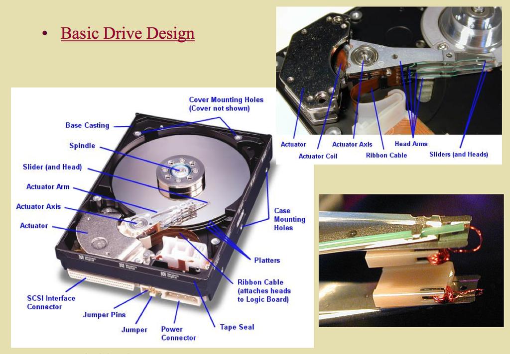
54 Control System Hardware Implementation - Factors Sensor input dynamic range, sampling rate, number of sensor inputs interface, polled or interrupt driven. Control algorithm fixed point or floating point, computational performance requirements, data storage requirement, program storage requirement. Controller output considerations Same as sensor input. Cost and Schedule COST versus product development. 54
55 Control System Hardware Implementation - Typical Plant Parameters Parameter Position Speed Acceleration Sensing Method Potentiometer (linear or angular) LVDT (Linear) Resolver (Angular) Optical Encoder (Linear or Angular) Tachometer (RPM to voltage) Hall Effect (Frequency) Optical Encoder (Frequency) Piezoelectric Accelerometer Strain Gage Accelerometer 55
56 Control System Hardware Implementation - Typical Plant Parameters Parameter Temperature Pressure Force Flow Rate Sensing Method Thermocouple Semiconductor Junction Thermisotr Strain Gage Piezoelectric Force Transducer Strain Gage Piezoelectric Force Transducer Differential Pressure Impeller (Frequency) Thermal (Differential temperature) 56
57 Control System Hardware Implementation - Factors LNA BPF VGA ADC Data to DSP DSP Input Schematic Diagram VGA Control from DSP Input Signal Conditioning Amplification of sensor signals, filtered, variable gain amplifier for adjustment, analogue to digital converter and interface to DSP. Controller Response local control - no operator inout control by another processor through a port - interactive control 57
58 Control System Hardware Implementation - Factors DAC LPF Buffer PA Data from DSP Plant Drive PA Control from DSP PWM Plant Drive DSP Output Schematic Diagram Controller Output Output signal is converted back to analogue signal with a DAC, filtered, fed to power amplifier. 58
59 Control System Hardware Implementation - Method Translate the system requirements into a design specification Translate the design specification into a functional block diagram. Optimize the block diagram. Translate the block diagram into a mathematical model. Optimize the mathematical model. 59

60 Control System Hardware Implementation - Block Diagram 60
61 Control System Hardware Implementation - Case Studies Computer Hard disk Control System. This case study demonstrates the ability to perform classical digital control design by going through the design of a computer hard-disk read/write head position controller. Automobile Active Suspension System. The vehicle suspension system is responsible for driving comfort and safety as the suspension caries the vehicle body and transmits all forces between the body and the road. By adding an active suspension comfort and safety are considerably improved compared to suspension setups with fixed properties. 61

62 Hard Disc Drive Description 62
 or vice versa transform electrical current into magnetic field (write the disk) They are high-precision, high- performance machines produced in very high volumes and sold at relatively low")
63 Hard Disc Drive Description Disk read/write heads are the small parts of a disk drive, that move above the disk platter and transform platter's magnetic field into electrical current (read the disk) or vice versa transform electrical current into magnetic field (write the disk) They are high-precision, high- performance machines produced in very high volumes and sold at relatively low cost. 63
64 Performance of a Hard Disc Drive There are three ways to measure the performance of a hard disk: Data Rate The data rate is the number of bytes per second that the drive can deliver to the CPU. Rates between 5 and 40 megabytes per second are common. Seek Time The seek time is the amount of time between when the CPU requests a file and when the first byte of the file is sent to the CPU. Times between 10 and 20 milliseconds are common. Capacity - The other important parameter is the capacity of the drive, which is the number of bytes it can hold. 64
65 65

66 Hard Disc Drive Description In a hard drive, the heads 'fly' above the disk surface with clearance of as little as 3 nanometres. The "flying height" is constantly decreasing to enable higher areal density. The flying height of the head is controlled by the design of an air-bearing etched onto the disk-facing surface of the slider. The role of the air bearing is to maintain the flying height constant as the head moves over the surface of the disk. If the head hits the disk's surface, a catastrophic head crash can result. 66


67 Hard Disc Drive Construction Details Platters of a Hard disc Hard disc head The microphotograph of the head shows that the size of the front face is about 0.3 mm. One functional part of the head is the round, orange structure in the middle - the lithographically defined copper coil of the write transducer. 67

68 Hard Disc Drive Description The plates are manufactured to amazing tolerances and are mirrorsmooth and typically spin at 3,600 or 7,200 rpm when the drive is operating. The light and fast-moving arm holds the read/write heads and is controlled by the voice-coil actuator. The arm is able to move the heads from the hub to the edge of the drive and can do this, back and forth, up to 50 times per second. In order to keep the magnetic head as close to the disk surface as possible, a self-pressurized air-bearing design is used for the sliders. 68
69 Design Challenges To design each of the four main components of the disk drive servo system plant dynamics, sensors, actuators, and control algorithms and to reduce the effect of mechanical disturbances to the drive. Disturbances arise from many sources: external shocks and vibrations, mechanical imperfections in the bearings of the disk spindle, disk vibrations, turbulent flow over the actuator due to air currents generated by the rapidly spinning disks, and the occasional contact between the slider and the disk. Plant dynamics which affect servo performance are mechanical resonances in the suspension (the leaf spring that holds the head against the disk), the actuator arm, the pivot bearing, and the voice coil. 69
70 Design Challenges The pivot bearing also has nonlinear friction dynamics, which include hysteresis and which primarily affect seek performance. Flutter vibration modes in the disks and other modes in the spindle contribute to tracking errors by moving the data track relative to an inertial frame of reference. Noise and distortion are two other important sources of tracking error in disk drives. Noise arises not only from electronics, but also from the magnetic media. The magnetoresistive head readers are nonlinear devices. Quantization noise is, of course, present in this digital control system. 70

71 Functional Block Diagram 71
72 Computer Hard Disc Drive - Transfer Function Using Newton's law, a simple model for the read/write head is the differential equation: where J is the inertia of the head assembly, C is the viscous damping coefficient of the bearings, K is the return spring constant, Ki is the motor torque constant, θ is the angular position of the head, and i is the input current. Taking the Laplace transform, the transfer function from i to θ is Using the values J = 0.01 kg m 2, C = Nm/(rad/sec), K = 10 Nm/ rad, and Ki = 0.05 Nm/rad, form the transfer function description of this system. Transfer function: 72
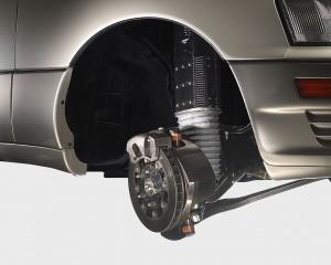
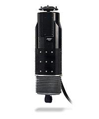
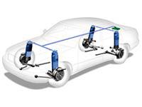
73 Control System Performance Step Response with large Phase margin Step response with filter Step response with controller implemented 73
74 Active Suspension Systems - Introduction Active or adaptive suspension technology controls the vertical movement of the wheels with an onboard system rather than the movement being determined entirely by the road surface. The system virtually eliminates body roll and pitch variation in many driving situations including cornering, accelerating, and braking. This technology allows car manufacturers to achieve a greater degree of ride quality and car handling by keeping the tires perpendicular to the road in corners, allowing better traction and control. 74
75 Control System Hardware Implementation - Active Suspension Systems Studies The vehicle suspension system is responsible for driving comfort and safety as the suspension caries the vehicle body and transmits all forces between the body and the road. Active systems enable the suspension system to adapt to various driving conditions. By adding a variable damper and/or spring, driving comfort and safety are considerably improved compared to suspension setups with fixed properties. 75
76 Suspension Systems - Safety and Stability Issues Safety is the result of a good suspension design in terms of wheel suspension, springing, steering, and braking, and is reflected in an optimal dynamic behaviour of the vehicle. Tire load variation is an indicator for the road contact and can be used for determining a quantitative value for safety. Driving comfort results from keeping the physiological stress that the vehicle occupants are subjected to by vibrations, noise, and climatic conditions down to as low a level as possible. The acceleration of the body is an obvious quantity for the motion and vibration of the car body and can be used for determining a quantitative value for driving comfort. 76
77 Suspension Systems - Conflicting Criteria In order to improve the ride quality, it is necessary to isolate the body. To improve the ride stability, it is important to keep the tire in contact with the road surface. For a given suspension spring, the better isolation of the sprung mass from road disturbances can be achieved with a soft damping by allowing a larger suspension deflection. Better road contact can be achieved with a hard damping preventing unnecessary suspension deflections. Therefore, the ride quality and the drive stability are two conflicting criteria. 77
78 Suspension Systems - Currently Available Systems Currently three types of vehicle suspensions are used: passive, semi-active, and active. Systems implemented in automobiles today are based on hydraulic or pneumatic operation. These solutions do not satisfactorily solve the vehicle oscillation problem, or they are very expensive and increase the vehicle s energy consumption. Significant improvement of suspension performance is achieved by active systems, however, they are expensive and complex. 78
79 Suspension Systems - Model Inputs The system has ten inputs, six of which are exogenous and the others controllable. These inputs are: Exogenous: The road velocity inputs experienced at each wheel Vehicle pitch force (due to accelerating/braking/cornering the vehicle) Vehicle roll input (due to cornering the vehicle) Controllable: Actuator forces applied to the suspension system at each corner of the vehicle. Outputs The ride quality can be quantified by examining the vertical and angular accelerations of the vehicle body, as well as the ability for the vehicle to remain level regardless of operating conditions. 79
80 Suspension Systems - Operating Scenarios for modelling 1. Driving over a speed bump (generates a vertical velocity profile input). 2. Braking at 1 g by applying the appropriate pitch moment to the vehicle centre of gravity. 3. Cornering by applying the appropriate pitch and roll moment to the vehicle centre of gravity. 80


81 Suspension Systems - LQR Models Design of an LQR Control Strategy for Implementation on a Vehicular Active Suspension System Ben Creed, Nalaka Kahawatte, Scott Varnhagen 2010 University of California, Davis 81
82 Suspension Systems - Bose System The Bose system uses a linear electromagnetic motor (LEM) at each wheel in lieu of a conventional shock- and-spring setup. Amplifiers provide electricity to the motors in such a way that their power is regenerated with each compression of the system. The main benefit of the motors is that they are not limited by the inertia inherent in conventional fluid-based dampers. As a result, an LEM can extend and compress at a much greater speed, virtually eliminating all vibrations in the passenger cabin. The wheel's motion can be so finely controlled that the body of the car remains level regardless of what's happening at the wheel. The LEM can also counteract the body motion of the car while accelerating, braking, and cornering, giving the driver a greater sense of control. 82

83 Bose Active Suspension System 83

84 Active Suspension Systems Bose Active Suspension 84

85 Active Suspension Systems The Siemens ecorner project The ecorner concept replaces the conventional wheel suspension with hydraulic shock absorbers, mechanical steering, hydraulic brakes and internal combustion engines with integrated in-wheel systems 85
86 Resources Feedback Control of Dynamic Systems, Gene Franklin, David Powell and Abbas Emami-Naeini, Pearson Prentice-Hall, Feedback Control Systems, Charles Phillips and Royce Harbour, Prentice-Hall, Mechatronics, G.S. Hegde, Jones and Bartlett Publishers LLC, Introduction to Mechatronics and Measurement Systems, A. Alciatore and M. Histand, McGraw Hill,
87 Lecture 1: Introduction to Smart Materials and Systems Lecture 2: Sensor technologies for smart systems and their evaluation criteria. Lecture 3: Actuator technologies for smart systems and their evaluation criteria. Lecture 4: Piezoelectric Materials and their Applications. Lecture 5: Control System Technologies. Lecture 6: Smart System Applications. S. Eswar Prasad, Adjunct Professor, Department of Mechanical & Industrial Engineering, Chairman, Piemades Inc, Piemades, Inc. 87
COVENANT UNIVERSITY NIGERIA TUTORIAL KIT OMEGA SEMESTER PROGRAMME: MECHANICAL ENGINEERING
 COVENANT UNIVERSITY NIGERIA TUTORIAL KIT OMEGA SEMESTER PROGRAMME: MECHANICAL ENGINEERING COURSE: MCE 527 DISCLAIMER The contents of this document are intended for practice and leaning purposes at the
Sensors and Sensing Motors, Encoders and Motor Control
 Sensors and Sensing Motors, Encoders and Motor Control Todor Stoyanov Mobile Robotics and Olfaction Lab Center for Applied Autonomous Sensor Systems Örebro University, Sweden todor.stoyanov@oru.se 05.11.2015
Fundamentals of Servo Motion Control
 Fundamentals of Servo Motion Control The fundamental concepts of servo motion control have not changed significantly in the last 50 years. The basic reasons for using servo systems in contrast to open
Position Control of DC Motor by Compensating Strategies
 Position Control of DC Motor by Compensating Strategies S Prem Kumar 1 J V Pavan Chand 1 B Pangedaiah 1 1. Assistant professor of Laki Reddy Balireddy College Of Engineering, Mylavaram Abstract - As the
Sensors and Sensing Motors, Encoders and Motor Control
 Sensors and Sensing Motors, Encoders and Motor Control Todor Stoyanov Mobile Robotics and Olfaction Lab Center for Applied Autonomous Sensor Systems Örebro University, Sweden todor.stoyanov@oru.se 13.11.2014
PYKC 7 March 2019 EA2.3 Electronics 2 Lecture 18-1
 In this lecture, we will examine a very popular feedback controller known as the proportional-integral-derivative (PID) control method. This type of controller is widely used in industry, does not require
Hydraulic Actuator Control Using an Multi-Purpose Electronic Interface Card
 Hydraulic Actuator Control Using an Multi-Purpose Electronic Interface Card N. KORONEOS, G. DIKEAKOS, D. PAPACHRISTOS Department of Automation Technological Educational Institution of Halkida Psaxna 34400,
MEM01: DC-Motor Servomechanism
 MEM01: DC-Motor Servomechanism Interdisciplinary Automatic Controls Laboratory - ME/ECE/CHE 389 February 5, 2016 Contents 1 Introduction and Goals 1 2 Description 2 3 Modeling 2 4 Lab Objective 5 5 Model
CHAPTER 4 PID CONTROLLER BASED SPEED CONTROL OF THREE PHASE INDUCTION MOTOR
 36 CHAPTER 4 PID CONTROLLER BASED SPEED CONTROL OF THREE PHASE INDUCTION MOTOR 4.1 INTRODUCTION Now a day, a number of different controllers are used in the industry and in many other fields. In a quite
Developer Techniques Sessions
 1 Developer Techniques Sessions Physical Measurements and Signal Processing Control Systems Logging and Networking 2 Abstract This session covers the technologies and configuration of a physical measurement
Active Vibration Isolation of an Unbalanced Machine Tool Spindle
 Active Vibration Isolation of an Unbalanced Machine Tool Spindle David. J. Hopkins, Paul Geraghty Lawrence Livermore National Laboratory 7000 East Ave, MS/L-792, Livermore, CA. 94550 Abstract Proper configurations
Figure 1.1: Quanser Driving Simulator
 1 INTRODUCTION The Quanser HIL Driving Simulator (QDS) is a modular and expandable LabVIEW model of a car driving on a closed track. The model is intended as a platform for the development, implementation
DEPARTMENT OF ELECTRICAL AND ELECTRONIC ENGINEERING BANGLADESH UNIVERSITY OF ENGINEERING & TECHNOLOGY EEE 402 : CONTROL SYSTEMS SESSIONAL
 DEPARTMENT OF ELECTRICAL AND ELECTRONIC ENGINEERING BANGLADESH UNIVERSITY OF ENGINEERING & TECHNOLOGY EEE 402 : CONTROL SYSTEMS SESSIONAL Experiment No. 1(a) : Modeling of physical systems and study of
Ch 5 Hardware Components for Automation
 Ch 5 Hardware Components for Automation Sections: 1. Sensors 2. Actuators 3. Analog-to-Digital Conversion 4. Digital-to-Analog Conversion 5. Input/Output Devices for Discrete Data Computer-Process Interface
Figure 1: Unity Feedback System. The transfer function of the PID controller looks like the following:
 Islamic University of Gaza Faculty of Engineering Electrical Engineering department Control Systems Design Lab Eng. Mohammed S. Jouda Eng. Ola M. Skeik Experiment 3 PID Controller Overview This experiment
Loop Design. Chapter Introduction
 Chapter 8 Loop Design 8.1 Introduction This is the first Chapter that deals with design and we will therefore start by some general aspects on design of engineering systems. Design is complicated because
Automatic Control Systems 2017 Spring Semester
 Automatic Control Systems 2017 Spring Semester Assignment Set 1 Dr. Kalyana C. Veluvolu Deadline: 11-APR - 16:00 hours @ IT1-815 1) Find the transfer function / for the following system using block diagram
Chapter 5. Tracking system with MEMS mirror
 Chapter 5 Tracking system with MEMS mirror Up to now, this project has dealt with the theoretical optimization of the tracking servo with MEMS mirror through the use of simulation models. For these models
Introduction to Measurement Systems
 MFE 3004 Mechatronics I Measurement Systems Dr Conrad Pace Page 4.1 Introduction to Measurement Systems Role of Measurement Systems Detection receive an external stimulus (ex. Displacement) Selection measurement
AC : A STUDENT-ORIENTED CONTROL LABORATORY US- ING PROGRAM CC
 AC 2011-490: A STUDENT-ORIENTED CONTROL LABORATORY US- ING PROGRAM CC Ziqian Liu, SUNY Maritime College Ziqian Liu received the Ph.D. degree from the Southern Illinois University Carbondale in 2005. He
Automatic Control Systems
 Automatic Control Systems Lecture-1 Basic Concepts of Classical control Emam Fathy Department of Electrical and Control Engineering email: emfmz@yahoo.com 1 What is Control System? A system Controlling
of harmonic cancellation algorithms The internal model principle enable precision motion control Dynamic control
 Dynamic control Harmonic cancellation algorithms enable precision motion control The internal model principle is a 30-years-young idea that serves as the basis for a myriad of modern motion control approaches.
Servo Tuning. Dr. Rohan Munasinghe Department. of Electronic and Telecommunication Engineering University of Moratuwa. Thanks to Dr.
 Servo Tuning Dr. Rohan Munasinghe Department. of Electronic and Telecommunication Engineering University of Moratuwa Thanks to Dr. Jacob Tal Overview Closed Loop Motion Control System Brain Brain Muscle
JUNE 2014 Solved Question Paper
 JUNE 2014 Solved Question Paper 1 a: Explain with examples open loop and closed loop control systems. List merits and demerits of both. Jun. 2014, 10 Marks Open & Closed Loop System - Advantages & Disadvantages
DC SERVO MOTOR CONTROL SYSTEM
 DC SERVO MOTOR CONTROL SYSTEM MODEL NO:(PEC - 00CE) User Manual Version 2.0 Technical Clarification /Suggestion : / Technical Support Division, Vi Microsystems Pvt. Ltd., Plot No :75,Electronics Estate,
BSNL TTA Question Paper Control Systems Specialization 2007
 BSNL TTA Question Paper Control Systems Specialization 2007 1. An open loop control system has its (a) control action independent of the output or desired quantity (b) controlling action, depending upon
Control Design for Servomechanisms July 2005, Glasgow Detailed Training Course Agenda
 Control Design for Servomechanisms 12 14 July 2005, Glasgow Detailed Training Course Agenda DAY 1 INTRODUCTION TO SYSTEMS AND MODELLING 9.00 Introduction The Need For Control - What Is Control? - Feedback
International Journal of Research in Advent Technology Available Online at:
 OVERVIEW OF DIFFERENT APPROACHES OF PID CONTROLLER TUNING Manju Kurien 1, Alka Prayagkar 2, Vaishali Rajeshirke 3 1 IS Department 2 IE Department 3 EV DEpartment VES Polytechnic, Chembur,Mumbai 1 manjulibu@gmail.com
Electro-hydraulic Servo Valve Systems
 Fluidsys Training Centre, Bangalore offers an extensive range of skill-based and industry-relevant courses in the field of Pneumatics and Hydraulics. For more details, please visit the website: https://fluidsys.org
GE420 Laboratory Assignment 8 Positioning Control of a Motor Using PD, PID, and Hybrid Control
 GE420 Laboratory Assignment 8 Positioning Control of a Motor Using PD, PID, and Hybrid Control Goals for this Lab Assignment: 1. Design a PD discrete control algorithm to allow the closed-loop combination
ELG3336 Design of Mechatronics System
 ELG3336 Design of Mechatronics System Elements of a Data Acquisition System 2 Analog Signal Data Acquisition Hardware Your Signal Data Acquisition DAQ Device System Computer Cable Terminal Block Data Acquisition
Automatic Control Motion control Advanced control techniques
 Automatic Control Motion control Advanced control techniques (luca.bascetta@polimi.it) Politecnico di Milano Dipartimento di Elettronica, Informazione e Bioingegneria Motivations (I) 2 Besides the classical
CHAPTER 2 PID CONTROLLER BASED CLOSED LOOP CONTROL OF DC DRIVE
 23 CHAPTER 2 PID CONTROLLER BASED CLOSED LOOP CONTROL OF DC DRIVE 2.1 PID CONTROLLER A proportional Integral Derivative controller (PID controller) find its application in industrial control system. It
Control Systems Overview REV II
 Control Systems Overview REV II D R. T A R E K A. T U T U N J I M E C H A C T R O N I C S Y S T E M D E S I G N P H I L A D E L P H I A U N I V E R S I T Y 2 0 1 4 Control Systems The control system is
Step vs. Servo Selecting the Best
 Step vs. Servo Selecting the Best Dan Jones Over the many years, there have been many technical papers and articles about which motor is the best. The short and sweet answer is let s talk about the application.
A PID Controller for Real-Time DC Motor Speed Control using the C505C Microcontroller
 A PID Controller for Real-Time DC Motor Speed Control using the C505C Microcontroller Sukumar Kamalasadan Division of Engineering and Computer Technology University of West Florida, Pensacola, FL, 32513
Rotary Motion Servo Plant: SRV02. Rotary Experiment #02: Position Control. SRV02 Position Control using QuaRC. Student Manual
 Rotary Motion Servo Plant: SRV02 Rotary Experiment #02: Position Control SRV02 Position Control using QuaRC Student Manual Table of Contents 1. INTRODUCTION...1 2. PREREQUISITES...1 3. OVERVIEW OF FILES...2
(1) Identify individual entries in a Control Loop Diagram. (2) Sketch Bode Plots by hand (when we could have used a computer
 Identify individual entries in a Control Loop Diagram. (2) Sketch Bode Plots by hand (when we could have used a computer") Last day: (1) Identify individual entries in a Control Loop Diagram (2) Sketch Bode Plots by hand (when we could have used a computer program to generate sketches). How might this be useful? Can more clearly
Last day: (1) Identify individual entries in a Control Loop Diagram (2) Sketch Bode Plots by hand (when we could have used a computer program to generate sketches). How might this be useful? Can more clearly
CS545 Contents XIV. Components of a Robotic System. Signal Processing. Reading Assignment for Next Class
 CS545 Contents XIV Components of a Robotic System Power Supplies and Power Amplifiers Actuators Transmission Sensors Signal Processing Linear filtering Simple filtering Optimal filtering Reading Assignment
Advanced Servo Tuning
 Advanced Servo Tuning Dr. Rohan Munasinghe Department of Electronic and Telecommunication Engineering University of Moratuwa Servo System Elements position encoder Motion controller (software) Desired
MAE106 Laboratory Exercises Lab # 5 - PD Control of DC motor position
 MAE106 Laboratory Exercises Lab # 5 - PD Control of DC motor position University of California, Irvine Department of Mechanical and Aerospace Engineering Goals Understand how to implement and tune a PD
ME375 Lab Project. Bradley Boane & Jeremy Bourque April 25, 2018
 ME375 Lab Project Bradley Boane & Jeremy Bourque April 25, 2018 Introduction: The goal of this project was to build and program a two-wheel robot that travels forward in a straight line for a distance
Experiment 9. PID Controller
 Experiment 9 PID Controller Objective: - To be familiar with PID controller. - Noting how changing PID controller parameter effect on system response. Theory: The basic function of a controller is to execute
Comparative Study of PID and Fuzzy Controllers for Speed Control of DC Motor
 Comparative Study of PID and Fuzzy Controllers for Speed Control of DC Motor Osama Omer Adam Mohammed 1, Dr. Awadalla Taifor Ali 2 P.G. Student, Department of Control Engineering, Faculty of Engineering,
 EC6405 - CONTROL SYSTEM ENGINEERING Questions and Answers Unit - II Time Response Analysis Two marks 1. What is transient response? The transient response is the response of the system when the system
Where: (J LM ) is the load inertia referred to the motor shaft. 8.0 CONSIDERATIONS FOR THE CONTROL OF DC MICROMOTORS. 8.
 is the load inertia referred to the motor shaft. 8.0 CONSIDERATIONS FOR THE CONTROL OF DC MICROMOTORS. 8.") Where: (J LM ) is the load inertia referred to the motor shaft. 8.0 CONSIDERATIONS FOR THE CONTROL OF DC MICROMOTORS 8.1 General Comments Due to its inherent qualities the Escap micromotor is very suitable
Where: (J LM ) is the load inertia referred to the motor shaft. 8.0 CONSIDERATIONS FOR THE CONTROL OF DC MICROMOTORS 8.1 General Comments Due to its inherent qualities the Escap micromotor is very suitable
Lab 11. Speed Control of a D.C. motor. Motor Characterization
 Lab 11. Speed Control of a D.C. motor Motor Characterization Motor Speed Control Project 1. Generate PWM waveform 2. Amplify the waveform to drive the motor 3. Measure motor speed 4. Estimate motor parameters
TRACK-FOLLOWING CONTROLLER FOR HARD DISK DRIVE ACTUATOR USING QUANTITATIVE FEEDBACK THEORY
 Proceedings of the IASTED International Conference Modelling, Identification and Control (AsiaMIC 2013) April 10-12, 2013 Phuket, Thailand TRACK-FOLLOWING CONTROLLER FOR HARD DISK DRIVE ACTUATOR USING
Design of Different Controller for Cruise Control System
 Design of Different Controller for Cruise Control System Anushek Kumar 1, Prof. (Dr.) Deoraj Kumar Tanti 2 1 Research Scholar, 2 Associate Professor 1,2 Electrical Department, Bit Sindri Dhanbad, (India)
Dr Ian R. Manchester
 Week Content Notes 1 Introduction 2 Frequency Domain Modelling 3 Transient Performance and the s-plane 4 Block Diagrams 5 Feedback System Characteristics Assign 1 Due 6 Root Locus 7 Root Locus 2 Assign
A Machine Tool Controller using Cascaded Servo Loops and Multiple Feedback Sensors per Axis
 A Machine Tool Controller using Cascaded Servo Loops and Multiple Sensors per Axis David J. Hopkins, Timm A. Wulff, George F. Weinert Lawrence Livermore National Laboratory 7000 East Ave, L-792, Livermore,
Control System Design for Tricopter using Filters and PID controller
 Control System Design for Tricopter using Filters and PID controller Abstract The purpose of this paper is to present the control system design of Tricopter. We have presented the implementation of control
Embedded Control Project -Iterative learning control for
 Embedded Control Project -Iterative learning control for Author : Axel Andersson Hariprasad Govindharajan Shahrzad Khodayari Project Guide : Alexander Medvedev Program : Embedded Systems and Engineering
CSE 3215 Embedded Systems Laboratory Lab 5 Digital Control System
 Introduction CSE 3215 Embedded Systems Laboratory Lab 5 Digital Control System The purpose of this lab is to introduce you to digital control systems. The most basic function of a control system is to
Chapter 2 The Test Benches
 Chapter 2 The Test Benches 2.1 An Active Hydraulic Suspension System Using Feedback Compensation The structure of the active hydraulic suspension (active isolation configuration) is presented in Fig. 2.1.
Robot Joint Angle Control Based on Self Resonance Cancellation Using Double Encoders
 Robot Joint Angle Control Based on Self Resonance Cancellation Using Double Encoders Akiyuki Hasegawa, Hiroshi Fujimoto and Taro Takahashi 2 Abstract Research on the control using a load-side encoder for
Using Magnetic Sensors for Absolute Position Detection and Feedback. Kevin Claycomb University of Evansville
 Using Magnetic Sensors for Absolute Position Detection and Feedback. Kevin Claycomb University of Evansville Using Magnetic Sensors for Absolute Position Detection and Feedback. Abstract Several types
PROCESS DYNAMICS AND CONTROL
 Objectives of the Class PROCESS DYNAMICS AND CONTROL CHBE320, Spring 2018 Professor Dae Ryook Yang Dept. of Chemical & Biological Engineering What is process control? Basics of process control Basic hardware
Draw the symbol and state the applications of : 1) Push button switch 2) 3) Solenoid valve 4) Limit switch ( 1m each) Ans: 1) Push Button
 Push button switch 2) 3) Solenoid valve 4) Limit switch ( 1m each) Ans: 1) Push Button") Subject Code: 17641Model AnswerPage 1 of 16 Important suggestions to examiners: 1) The answers should be examined by key words and not as word-to-word as given in the model answer scheme. 2) The model
Subject Code: 17641Model AnswerPage 1 of 16 Important suggestions to examiners: 1) The answers should be examined by key words and not as word-to-word as given in the model answer scheme. 2) The model
OPTIMAL AND PID CONTROLLER FOR CONTROLLING CAMERA S POSITION IN UNMANNED AERIAL VEHICLES
 International Journal of Information Technology, Modeling and Computing (IJITMC) Vol.1,No.4,November 2013 OPTIMAL AND PID CONTROLLER FOR CONTROLLING CAMERA S POSITION IN UNMANNED AERIAL VEHICLES MOHAMMAD
Dr Ian R. Manchester Dr Ian R. Manchester Amme 3500 : Root Locus Design
 Week Content Notes 1 Introduction 2 Frequency Domain Modelling 3 Transient Performance and the s-plane 4 Block Diagrams 5 Feedback System Characteristics Assign 1 Due 6 Root Locus 7 Root Locus 2 Assign
UNIT 2: DC MOTOR POSITION CONTROL
 UNIT 2: DC MOTOR POSITION CONTROL 2.1 INTRODUCTION This experiment aims to show the mathematical model of a DC motor and how to determine the physical parameters of a DC motor model. Once the model is
Laboratory Assignment 5 Digital Velocity and Position control of a D.C. motor
 Laboratory Assignment 5 Digital Velocity and Position control of a D.C. motor 2.737 Mechatronics Dept. of Mechanical Engineering Massachusetts Institute of Technology Cambridge, MA0239 Topics Motor modeling
System Inputs, Physical Modeling, and Time & Frequency Domains
 System Inputs, Physical Modeling, and Time & Frequency Domains There are three topics that require more discussion at this point of our study. They are: Classification of System Inputs, Physical Modeling,
Module 1: Introduction to Experimental Techniques Lecture 2: Sources of error. The Lecture Contains: Sources of Error in Measurement
 The Lecture Contains: Sources of Error in Measurement Signal-To-Noise Ratio Analog-to-Digital Conversion of Measurement Data A/D Conversion Digitalization Errors due to A/D Conversion file:///g /optical_measurement/lecture2/2_1.htm[5/7/2012
Study on Repetitive PID Control of Linear Motor in Wafer Stage of Lithography
 Available online at www.sciencedirect.com Procedia Engineering 9 (01) 3863 3867 01 International Workshop on Information and Electronics Engineering (IWIEE) Study on Repetitive PID Control of Linear Motor
Effective Teaching Learning Process for PID Controller Based on Experimental Setup with LabVIEW
 Effective Teaching Learning Process for PID Controller Based on Experimental Setup with LabVIEW Komal Sampatrao Patil & D.R.Patil Electrical Department, Walchand college of Engineering, Sangli E-mail :
5. Transducers Definition and General Concept of Transducer Classification of Transducers
 5.1. Definition and General Concept of Definition The transducer is a device which converts one form of energy into another form. Examples: Mechanical transducer and Electrical transducer Electrical A
Estimation of State Variables of Active Suspension System using Kalman Filter
 International Journal of Current Engineering and Technology E-ISSN 2277 416, P-ISSN 2347 5161 217 INPRESSCO, All Rights Reserved Available at http://inpressco.com/category/ijcet Research Article Estimation
6.270 Lecture. Control Systems
 6.270 Lecture Control Systems Steven Jorgensen Massachusetts Institute of Technology January 2014 Overview of Lecture Feed Forward Open Loop Controller Pros and Cons Bang-Bang Closed Loop Controller Intro
Lecture 5 Introduction to control
 Lecture 5 Introduction to control Feedback control is a way of automatically adjusting a variable to a desired value despite possible external influence or variations. Eg: Heating your house. No feedback
Design of a Simulink-Based Control Workstation for Mobile Wheeled Vehicles with Variable-Velocity Differential Motor Drives
 Design of a Simulink-Based Control Workstation for Mobile Wheeled Vehicles with Variable-Velocity Differential Motor Drives Kevin Block, Timothy De Pasion, Benjamin Roos, Alexander Schmidt Gary Dempsey
Experiment Of Speed Control for an Electric Trishaw Based on PID Control Algorithm
 International Journal of Mechanical & Mechatronics Engineering IJMME-IJENS Vol:17 No:02 38 Experiment Of Speed Control for an Electric Trishaw Based on PID Control Algorithm Shahrizal Saat 1 *, Mohd Nabil
Electronic Instrumentation and Measurements
 Electronic Instrumentation and Measurements A fundamental part of many electromechanical systems is a measurement system that composed of four basic parts: Sensors Signal Conditioning Analog-to-Digital-Conversion
A Searching Analyses for Best PID Tuning Method for CNC Servo Drive
 International Journal of Science and Engineering Investigations vol. 7, issue 76, May 2018 ISSN: 2251-8843 A Searching Analyses for Best PID Tuning Method for CNC Servo Drive Ferit Idrizi FMI-UP Prishtine,
Vibration Control of Mechanical Suspension System Using Active Force Control
 Vibration Control of Mechanical Suspension System Using Active Force Control Maziah Mohamad, Musa Mailah, Abdul Halim Muhaimin Department of Applied Mechanics Faculty of Mechanical Engineering Universiti
Control System Design of Magneto-rheoloical Damper under High-Impact Load
 Control System Design of Magneto-rheoloical Damper under High-Impact Load Bucai Liu College of Mechanical Engineering, University of Shanghai for Science and Technology 516 Jun Gong Road, Shanghai 200093,
Robust Control Design for Rotary Inverted Pendulum Balance
 Indian Journal of Science and Technology, Vol 9(28), DOI: 1.17485/ijst/216/v9i28/9387, July 216 ISSN (Print) : 974-6846 ISSN (Online) : 974-5645 Robust Control Design for Rotary Inverted Pendulum Balance
CRN: MET-487 Instrumentation and Automatic Control June 28, 2010 August 5, 2010 Professor Paul Lin
 CRN: 32030 MET-487 Instrumentation and Automatic Control June 28, 2010 August 5, 2010 Professor Paul Lin Course Description: Class 2, Lab 2, Cr. 3, Junior class standing and 216 Instrumentation for pressure,
CHAPTER 6. CALCULATION OF TUNING PARAMETERS FOR VIBRATION CONTROL USING LabVIEW
 130 CHAPTER 6 CALCULATION OF TUNING PARAMETERS FOR VIBRATION CONTROL USING LabVIEW 6.1 INTRODUCTION Vibration control of rotating machinery is tougher and a challenging challengerical technical problem.
Paul Schafbuch. Senior Research Engineer Fisher Controls International, Inc.
 Paul Schafbuch Senior Research Engineer Fisher Controls International, Inc. Introduction Achieving optimal control system performance keys on selecting or specifying the proper flow characteristic. Therefore,
MEM380 Applied Autonomous Robots I Winter Feedback Control USARSim
 MEM380 Applied Autonomous Robots I Winter 2011 Feedback Control USARSim Transforming Accelerations into Position Estimates In a perfect world It s not a perfect world. We have noise and bias in our acceleration
Andrea Zanchettin Automatic Control 1 AUTOMATIC CONTROL. Andrea M. Zanchettin, PhD Spring Semester, Linear control systems design
 Andrea Zanchettin Automatic Control 1 AUTOMATIC CONTROL Andrea M. Zanchettin, PhD Spring Semester, 2018 Linear control systems design Andrea Zanchettin Automatic Control 2 The control problem Let s introduce
Lab 23 Microcomputer-Based Motor Controller
 Lab 23 Microcomputer-Based Motor Controller Page 23.1 Lab 23 Microcomputer-Based Motor Controller This laboratory assignment accompanies the book, Embedded Microcomputer Systems: Real Time Interfacing,
CIS009-2, Mechatronics Signals & Motors
 CIS009-2, Signals & Motors Bedfordshire 13 th December 2012 Outline 1 2 3 4 5 6 7 8 3 Signals Two types of signals exist: 4 Bedfordshire 52 Analogue signal In an analogue signal voltages and currents continuously
ENGG4420 END OF CHAPTER 1 QUESTIONS AND PROBLEMS
 CHAPTER 1 By Radu Muresan University of Guelph Page 1 ENGG4420 END OF CHAPTER 1 QUESTIONS AND PROBLEMS September 25 12 12:45 PM QUESTIONS SET 1 1. Give 3 advantages of feedback in control. 2. Give 2 disadvantages
AutoBench 1.1. software benchmark data book.
 AutoBench 1.1 software benchmark data book Table of Contents Angle to Time Conversion...2 Basic Integer and Floating Point...4 Bit Manipulation...5 Cache Buster...6 CAN Remote Data Request...7 Fast Fourier
Lecture 9. Lab 16 System Identification (2 nd or 2 sessions) Lab 17 Proportional Control
 Lab 17 Proportional Control") 246 Lecture 9 Coming week labs: Lab 16 System Identification (2 nd or 2 sessions) Lab 17 Proportional Control Today: Systems topics System identification (ala ME4232) Time domain Frequency domain Proportional
246 Lecture 9 Coming week labs: Lab 16 System Identification (2 nd or 2 sessions) Lab 17 Proportional Control Today: Systems topics System identification (ala ME4232) Time domain Frequency domain Proportional
Glossary of terms. Short explanation
 Glossary Concept Module. Video Short explanation Abstraction 2.4 Capturing the essence of the behavior of interest (getting a model or representation) Action in the control Derivative 4.2 The control signal
EE 3TP4: Signals and Systems Lab 5: Control of a Servomechanism
 EE 3TP4: Signals and Systems Lab 5: Control of a Servomechanism Tim Davidson Ext. 27352 davidson@mcmaster.ca Objective To identify the plant model of a servomechanism, and explore the trade-off between
Cohen-coon PID Tuning Method; A Better Option to Ziegler Nichols-PID Tuning Method
 Cohen-coon PID Tuning Method; A Better Option to Ziegler Nichols-PID Tuning Method Engr. Joseph, E. A. 1, Olaiya O. O. 2 1 Electrical Engineering Department, the Federal Polytechnic, Ilaro, Ogun State,
Different Controller Terms
 Loop Tuning Lab Challenges Not all PID controllers are the same. They don t all use the same units for P-I-and D. There are different types of processes. There are different final element types. There
A Fast PID Tuning Algorithm for Feed Drive Servo Loop
 American Scientific Research Journal for Engineering, Technology, and Sciences (ASRJETS) ISSN (Print) 233-440, ISSN (Online) 233-4402 Global Society of Scientific Research and Researchers http://asrjetsjournal.org/
Ball Balancing on a Beam
 1 Ball Balancing on a Beam Muhammad Hasan Jafry, Haseeb Tariq, Abubakr Muhammad Department of Electrical Engineering, LUMS School of Science and Engineering, Pakistan Email: {14100105,14100040}@lums.edu.pk,
Job Sheet 2 Servo Control
 Job Sheet 2 Servo Control Electrical actuators are replacing hydraulic actuators in many industrial applications. Electric servomotors and linear actuators can perform many of the same physical displacement
Digital Control of MS-150 Modular Position Servo System
 IEEE NECEC Nov. 8, 2007 St. John's NL 1 Digital Control of MS-150 Modular Position Servo System Farid Arvani, Syeda N. Ferdaus, M. Tariq Iqbal Faculty of Engineering, Memorial University of Newfoundland
LECTURE 2: PD, PID, and Feedback Compensation. ( ) = + We consider various settings for Zc when compensating the system with the following RL:
 = + We consider various settings for Zc when compensating the system with the following RL:") LECTURE 2: PD, PID, and Feedback Compensation. 2.1 Ideal Derivative Compensation (PD) Generally, we want to speed up the transient response (decrease Ts and Tp). If we are lucky then a system s desired
LECTURE 2: PD, PID, and Feedback Compensation. 2.1 Ideal Derivative Compensation (PD) Generally, we want to speed up the transient response (decrease Ts and Tp). If we are lucky then a system s desired
Procidia Control Solutions Dead Time Compensation
 APPLICATION DATA Procidia Control Solutions Dead Time Compensation AD353-127 Rev 2 April 2012 This application data sheet describes dead time compensation methods. A configuration can be developed within
Cantonment, Dhaka-1216, BANGLADESH
 International Conference on Mechanical, Industrial and Energy Engineering 2014 26-27 December, 2014, Khulna, BANGLADESH ICMIEE-PI-140153 Electro-Mechanical Modeling of Separately Excited DC Motor & Performance
Analog Devices: High Efficiency, Low Cost, Sensorless Motor Control.
 Analog Devices: High Efficiency, Low Cost, Sensorless Motor Control. Dr. Tom Flint, Analog Devices, Inc. Abstract In this paper we consider the sensorless control of two types of high efficiency electric