3TM Vacuum Contactors
|
|
|
- Andrew Melton
- 6 years ago
- Views:
Transcription


1 Catalog HG Edition TM Vacuum Contactors Medium-Voltage Equipment siemens.com/3tm

2 2 HG11_23_01.tif
3 Contents 3TM Vacuum Contactors Medium-Voltage Equipment Catalog HG Invalid: Catalog Extract HG Contents Page Description 5 General 6 Construction and mode of operation 7 Ambient conditions and dielectric strength 10 Switching duties 11 Standards and type approval 13 Equipment Selection 15 Order number structure, configuration example 16 Selection of 3TM vacuum contactors 18 Secondary equipment 19 Special versions and additional equipment 21 Spare parts, accessories and rating plate Technical Data 25 Electrical data, dimensions and weights 26 Dimension drawings 29 Circuit diagrams 31 Transport dimensions and weights 35 3 Annex 37 Configuration instructions 38 Configuration aid Foldout page 4 The products and systems described in this catalog are manufactured and sold according to a certified management system (acc. to ISO 9001, ISO and BS OHSAS 18001). 3

4 R_HG11_173.tif 4

5 Contents Contents Page Description 5 General 6 1 R-HG tif Construction and mode of operation Applications 7 Switching medium 7 Design and function 7 Function and mode of operation 8 Control supply voltage, wide-area coils 8 Safety shutdown of the magnetic actuator in case of deviation from the normal closing time 8 Intermittent periodic duty and rapid operation 8 Mechanical closing latch (optional) 9 Closing and opening delay 9 Mounting position 9 Site altitude 9 Severe conditions 9 Industrial application: Refinery Ambient conditions and dielectric strength Ambient conditions 10 Dielectric strength 10 Switching duties, standards and type approval Utilization categories 11 Switching of motors 11 Switching of transformers 11 Surge protection via limiters 11 Switching of capacitors 11 Short-circuit protection 11 Short-circuit protection via HV HRC fuses 12 Coordinating the components of the motor circuit 12 Requirements 12 Short-circuit protection for class E2 controllers according to UL 347/CSA C Short-circuit protection via circuit-breaker 13 Overvoltage category 13 Trip-free mechanism 13 Standards and type approval 13 5
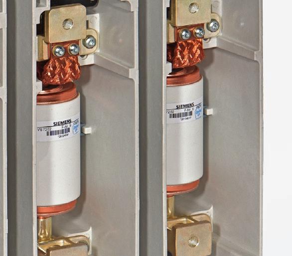
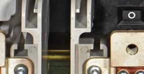
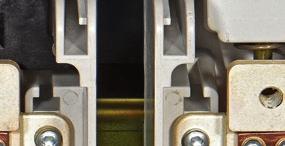
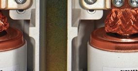
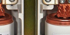
6 Description General 3TM vacuum contactors are electromechanical, monostable load breaking devices with a limited short-circuit making and breaking capacity. They can be used for high switching rates of up to one million electrical and mechanical operating cycles and unlimited operating time, as well as for fast switching frequencies. Contactor, front (high-voltage side) Contactor, rear (fixing side) R-HG tif 1 R-HG tif Contactor, side view 6 R-HG eps 3TM vacuum contactors the new contactor generation
 Transformers Capacitors, also back-to-back Reactors Resistive consumers.")
7 Description Construction and mode of operation Applications 3TM vacuum contactors are suitable for operational switching of AC circuits of any kind, such as: Three-phase motors for reversing, inversing or direct duty (utilization category AC-1 to AC-4) Transformers Capacitors, also back-to-back Reactors Resistive consumers. They are used in conveying and elevator systems, pumping stations, air conditioning systems, as well as in systems for reactive power compensation, on ships, in open-cast mining, in earthquake zones and in railway operation, and can therefore be found in almost every industrial sector. 1 Switching medium 3TM vacuum contactors make use of vacuum switching technology, which has been proven and fully developed for more than 40 years. Siemens vacuum interrupters operate constantly and reliably throughout their entire service life without any maintenance. HG11_23_02.tif Design and function 3TM vacuum contactors consist of: A high-voltage part, with vacuum interrupters, customer connections and position indicator A low-voltage part, with magnetic actuator and control electronics Auxiliary switches Optionally, a closing latch as well as a manual latch release (emergency off), and a shunt release. The high-voltage part contains individual, independent pole shells, which can take up the corresponding vacuum interrupters. In this way, various pole-center distances are possible. The vacuum interrupters are operated by a common magnetic actuator, which is characterized by a very low holding power in continuous operation. The auxiliary switches are located at the side of the operating mechanism and are freely accessible from the outside. A mechanical closing latch and corresponding latch release modules can be ordered separately. Remote tripping takes place via an electromagnetic shunt release. The manual mechanic latch release (emergency off) is available for various operating directions. Application, switching of consumers Symbols Application examples Medium-voltage three-phase motors Transformers Reactors Resistive consumers Capacitors M 3~ HG b eps HG b eps HG a eps HG a eps HG b eps Conveyor and elevator systems, compressors, ventilation and heating Ring-main units, industrial system distributions Industrial system distributions, DC-link reactors, reactive power compensation systems Heating resistors, electric furnaces Reactive power compensation systems, capacitor banks 7
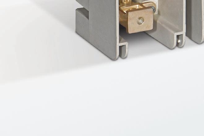
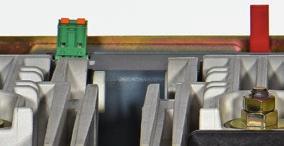
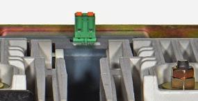
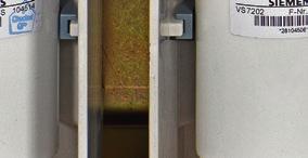
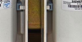
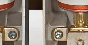
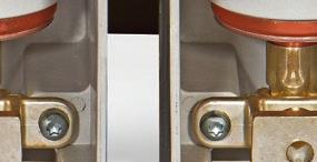
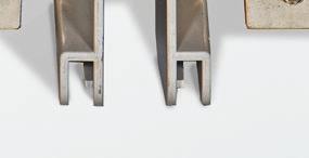
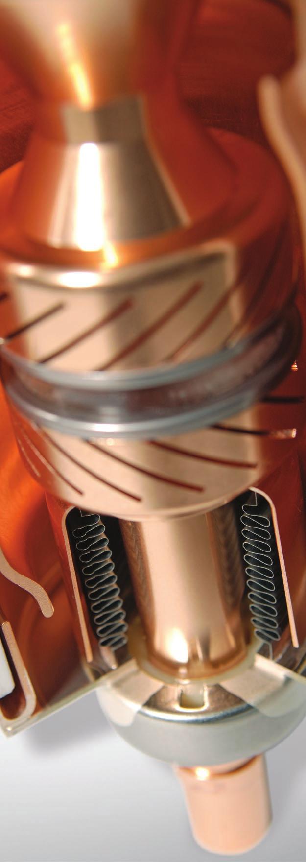
8 Description Construction and mode of operation Function and mode of operation 1 Contactor, side view (right) Contactor, top view 1 Molded-plastic housing (pole shell) 2 Operating mechanism box 3 Drive lever 4 Bearing 5 Guide nut + locknut 6 Magnet armature 7 Magnet system 8 Vacuum interrupter 9 Contact pressure spring 10 Connection, top 11 Flexible connector 12 Connection, bottom 13 Controller 14 Connection for control voltage A1 A2 (incl. supplied plug) 15 Connection for el.magn. release E1 E2 (incl. supplied plug) 16 Position indicator 17 Base plate (fixing) 18 Closing latch 19 Shunt release 20 Manual release (emergency off) 21 Earthing connection 22 Cover for latching 23 Auxiliary switch 24 Side plate with fixing bolts 25 Rating plate 26 Plug A1 A2 (and E1 E2) The drive lever (3) with the pivot point in A is designed as an angle lever. It represents the kinematic connection between the magnetic actuator and the vacuum interrupters. In case of non-excited magnet, the return springs keep the drive lever in "OPEN" position. Thus, the drive lever (3) is in its upper position via the bearing (4) of the guide nut (5). In this way, the contacts of the vacuum interrupter (8) are separated from each other, and thus kept in "OPEN" position. For closing, the magnet system (7) is excited. The magnet armature (6) attached to the drive lever (3) is thus attracted against the force of the two return springs. This releases the vacuum interrupter (8), so that the external air pressure can press the moving contact towards the fixed contact. The drive lever (3) compresses the contact pressure springs (9), thus generating an additional contact force. The distance between the bearing (4) and the guide nut (5) in "CLOSED" position is a measure for the wear of the vacuum interrupter. 3TM vacuum contactors can be used for cable or bar connections. The base plate (17) serves for installation without distortion through the four bolting holes. Control supply voltage, wide-area coils 3TM vacuum contactors can be optionally operated with DC or AC. The control supply voltage should correspond to the data on the rating plate. Customer-side modifications are possible considering the standards provided in the operating instructions. Safety shutdown of the magnetic actuator in case of deviation from the normal closing time 3TM vacuum contactors feature a safety shutdown to protect the magnet coils against non-conforming thermal overload during closing. Within certain limits, impermissible and nonconforming delays in the closing process are thus detected and the devices are protected from damage. Contactor, side view (left) Intermittent periodic duty and rapid operation 3TM vacuum contactors are able to perform fast switching frequencies for a short time. In case of switching under high current load, longer dead times have to be kept. In this case, please contact your responsible sales partner. 8
9 Description Construction and mode of operation Mechanical closing latch (optionally) When the 3TM vacuum contactor is closed, the mechanical closing latch (18) is activated. After reaching the latching position, there is an automatic changeover to no-load holding operation. Opening takes place via: Electromagnetic latch release (remote tripping via the electromagnetic shunt release) (19), or Manual mechanical latch release (20). When 3TM vacuum contactors are retrofitted (selection B at the 10 th position of the order number) with a closing latch or latch release, the following modules must be ordered and installed later: Mechanical closing latch with shunt release (19) Latch release mechanism to be operated manually with push or pull rod. Closing and opening delay 3TM vacuum contactors feature a short closing and opening time. (See page 27) They can also be configured with an additional closing and opening delay for selective operation with other contactors or fuses. Both delays are independent of each other and add to the closing and opening time. Modes of operation and operating directions: Mechanical latch release (emergency off) Manual latch release with push rod in direction A (10 th position of MLFB = F with MLFB supplement J67) Manual latch release with pull rod in direction B (10 th position of MLFB = F with MLFB supplement J68) Manual latch release via shunt release (push operation) 1 Mounting position 3TM vacuum contactors can be mounted in vertical and horizontal position: Mounting position As fixed-mounted design Mounted on a withdrawable part or a truck. Site altitude 3TM vacuum contactors can be used for various site altitudes. As a standard, 3TM vacuum contactors can be used from 1250 m to m above sea level. For higher site altitudes, a configuration is offered from 2000 m to 5000 m. Severe conditions For very heavy mechanical stress such as earthquakes or extraordinary shock and swinging loads, a special configuration is offered. Vertical wall mounting Horizontally on the back Vertical wall mounting, turned by 180 Suspended installation, with reduced parameters *) Observe the distance to high voltage and to earthed components! 9
10 Description Ambient conditions and dielectric strength 1 Ambient conditions 3TM vacuum contactors are suitable for operational use in the following climatic classes according to IEC 60721: Climatic ambient conditions: Class 3K4 1), Class 3K8H 2) Biological ambient conditions: Class 3B1 Mechanical ambient conditions: Class 3M3 Chemically active substances: Class 3C2 3) Mechanically active substances: Class 3S2 4) 1) Maximum of 24-hour mean: +70 C 2) Up to -40 C 3) Without appearance of saline fog and simultaneous condensation 4) Restriction: Clean insulation parts Dielectric strength The dielectric strength of air insulation decreases with increasing altitude due to low air density. According to IEC , the values of the rated lightning impulse withstand voltage and the rated short-duration power-frequency withstand voltage specified for 3TM vacuum contactors apply to a site altitude of 1000 m above sea level. For an altitude above 1000 m, the insulation level must be corrected. To select the devices, the following applies: U U 0 x K a U Rated withstand voltage under reference atmosphere U 0 Rated withstand voltage requested for the place of installation K a Altitude correction factor according to the opposite diagram Example: For a requested rated lightning impulse withstand voltage of 75 kv at an altitude of 2500 m, an insulation level of 90 kv under standard reference atmosphere is required as a minimum: 90 kv 75 kv x e 1 x ( )/ kv x
11 Description Switching duties Utilization categories In IEC , vacuum contactors are divided into different utilization categories. The opposite table shows typical applications in accordance with the respective utilization category. Switching of motors 3TM vacuum contactors are especially suitable for frequent operation of motors. As the chopping currents of the contactors are 3 A, no impermissibly high overvoltages are produced when accelerated motors are switched during normal operation. However, when high-voltage motors with starting currents of 600 A are stopped during start-up, switching overvoltages may arise. The magnitude of these overvoltages can be reduced to harmless values by means of special surge limiters. Switching of transformers Utilization categories AC-1 AC-2 AC-3 AC-4 Typical applications Non-inductive or slightly inductive loads, resistance furnaces Slip-ring motors: Starting, switching off Squirrel-cage motors: Starting, switching off during running Squirrel-cage motors: Starting, plugging 1), reversing 1), inching 2) 1) By plugging or reversing is understood stopping or reversing the motor rapidly by reversing motor primary connections while the motor is running 2) By inching is understood energizing a motor once or repeatedly for short periods to obtain small movements of the driven mechanism 1 When inductive currents are interrupted, current chopping can produce overvoltages at the contact gap. As the chopping current of the Siemens vacuum contactor is less than 3 A, no dangerous overvoltages are produced when the unloaded transformer is switched off. Surge protection via limiters Circuit diagram U1 V1 W1 M 3~ HG b eps Type of duty Switching of accelerated motors Overvoltages can arise as a consequence of multiple restrikes or by virtual current chopping, e.g. when motors are switched in braked condition or during start-up. Motors with a starting current 600 A are endangered. Safe protection against overvoltages is ensured by surge limiters. These can be arranged in parallel to the cable sealing ends, preferably in the cable compartment. Switching of capacitors 3TM vacuum contactors can interrupt capacitive currents up to 315 A up to the rated voltage of 12 kv without restrikes, and thus without overvoltages. Short-circuit protection U1 V1 W1 M 3~ U1 V1 W1 M 3~ HG b eps HG b eps Occasional switching of just accelerated motors in case of fault 1) Frequent switching in AC-4 operation 1) Circuit examples for surge protection of three-phase motors with a starting current 600 A 1) With surge limiter 3TM vacuum contactors are not designed to switch shortcircuit currents. Therefore, a short-circuit protection must be provided. The best protection is provided by HV HRC fuses or circuit-breakers. HV HRC fuses or or Circuitbreaker Switchdisconnector with HV HRC fuses Vacuum contactor Surge limiter HG d_en eps Consumer Switching devices in combination with a vacuum contactor 11
12 Description Switching duties 1 Short-circuit protection via HV HRC fuses At high short-circuit currents, HV HRC fuses have a currentlimiting effect, i.e. the fuse limits the short-circuit current to the let-through current. When selecting the fuses, the type of consumer must be observed, e.g. motor, transformer, capacitor. The opposite diagram shows an example for the coordination of an HV HRC fuse with a time-overcurrent protection. Example for the coordination of a HV HRC fuse characteristic 125 A with a motor characteristic 1 Characteristic of the HV HRC fuse 2 Characteristic of the time-overcurrent protection 3 Motor starting time 4 Motor starting current Sustained symmetrical short-circuit current (r.m.s. value) Coordinating the components of the motor circuit The time-current characteristic must be located on the right of the motor starting current (point A). The rated current of the HV HRC fuse-link must exceed the normal current of the motor. The current corresponding to the intersection B of the HV HRC fuse-link characteristic and the characteristic of the time-overcurrent protection must be higher than the minimum breaking current of the HV HRC fuse-link. If this is not feasible, it must be ensured that overload currents that are smaller than the minimum breaking current of the HV HRC fuse-link are interrupted by the switching device via the striker. This prevents thermal overloading of the HV HRC fuse-link, which would otherwise be destroyed. The selected HV HRC fuse-link limits the sustained symmetrical short-circuit current I k to the let-through current I D shown in the diagram for the current-limiting characteristics (I D as a function of I K for HV HRC fuse-links with different rated currents). The maximum tested let-through current is I D = 46 ka. Requirements It must be ensured that the vacuum contactor cannot open until the fuse has interrupted the overload current. If necessary, the contactor opening time must be extended. 3TM vacuum contactors feature the corresponding setting facility. This does not apply if a mechanical closing latch is used. In this case, the time delay between tripping of the fuse and the latch release signal must be considered by the operator. Due to the arising motor starting current, the instant when the motor starts represents the maximum stress for the HV HRC fuse. This stress must neither operate nor predamage the fuse. Other factors of influence on the stress of the HV HRC fuses are the starting time and the starting frequency of the motors. 12
13 Description Switching duties, standards and type approval Short-circuit protection for class E2 controllers according to UL 347/CSA C22.2 For using 3TM vacuum contactors as class E2 controllers, fuses are specified for short-circuit protection. If two fuselinks are connected in parallel, the symmetrical short-circuit current determined has to be divided by two, and the associated let-through current for one fuse-link must be stated. This value must then be multiplied by two in order to obtain the total let-through current, which must not exceed the permissible value for the vacuum contactor. The parallel connection should ensure that the resistance values in the two branches are almost the same. When the fuses operate, the vacuum contactor must be switched off. A suitable device, actuated by the striker of the HV HRC fuse-link, has to be provided. Short-circuit protection by circuit-breakers Consumers for which no suitable fuses are available can also be protected by circuit-breakers. During the longer break time of the circuit-breakers (as a rule, 35 to 60 ms), the symmetrical short-circuit current must not exceed the maximum permissible value. Overvoltage category 3TM vacuum contactors can be used up to overvoltage category III. When used in higher categories, surge arresters must be integrated in the control circuits. Trip-free mechanism The contacts of the 3TM vacuum contactors are trip-free. In the event of an opening command being given after a closing operation has been initiated, the moving contacts return to the open position and remain there even if the closing command is sustained. This means that the contacts are momentarily in the closed position. Standards 3TM vacuum contactors correspond to the standards: IEC/DIN EN High-voltage switchgear and controlgear Part 1: Common specifications IEC/DIN EN High-voltage switchgear and controlgear Part 106: Contactors and controllers GB/T14808 High voltage alternating current contactors and contactor-based motor-starters UL347, 6 th edition Medium-Voltage AC Contactors, Controllers, and Control Centers CSA C IEC , EN , EN , EN Electromagnetic compatibility (EMC) DNVGL-CG-0339 Classification and construction standards for ship technology. Type approval according to German X-ray regulations The vacuum interrupters fitted in the switching devices are type-approved in accordance with 8 of the X-ray regulations (RöV = Röntgenverordnung) of the Federal Republic of Germany as interference radiators, and they meet the requirements for interference radiators according to Annex 2 No. 5 of the latest RöV up to the rated voltage specified in the approval document. Performance in case of voltage dips or reductions of the control supply voltage U a 3TM vacuum contactors fulfill the requirements concerning voltage dips and reductions with the values requested according to IEC / , IEC Mirror contacts 3TM vacuum contactors are equipped with mirror contacts. Positive opening / Positive driving The auxiliary switches are mechanically connected with the operating system and are positively moved and driven (positive opening/closing). Degree of pollution 3TM vacuum contactors fulfill the conditions according to pollution degree 3. Degree of protection 3TM vacuum contactors fulfill the degree of protection IP43, except for the main circuit and the connections for which the degree of protection IP00 applies. 1 13


14 R-HG tif 14
15 Equipment Selection Contents Contents Page Equipment Selection 15 Order number structure, configuration example 16 Selection of 3TM vacuum contactors Voltage level 7.2 kv 18 Voltage level 12 kv 18 Voltage level 15 kv 18 HG11_23_03.tif Secondary equipment Operating voltage for magnet system 19 Additional components closing latch and latch release 19 Pole-center distance 19 Additional closing delay preset 20 Additional opening delay preset 20 Latch release voltage 20 Auxiliary contacts 20 Accessories 20 2 Special versions and additional equipment 21 Spare parts, accessories and rating plate 22 15
16 Equipment Selection Order number structure, configuration example 2 Order number structure 3TM vacuum contactors consist of a medium-voltage and a low-voltage part. The relevant data make up a 16-digit order number. The medium-voltage part covers the main electrical data of the poles. The low-voltage part covers all auxiliary devices which are necessary for operating and controlling the contactor. Order codes («) In case of special versions and additional equipment, -Z is added to the order number and explained in more detail with a 3-digit order code. Several order codes can be added to the order number in succession and in any sequence. In this context, the suffix -Z is listed only once. If a requested special version or additional equipment is not in the catalog and can therefore not be ordered via order code, it has to be identified with Y 9 9 and a clear text specification. The agreement hereto is made directly between your responsible sales partner and the order processing department in the Switchgear Factory Berlin. a: alphabetical n: numerical Position: Order codes Order No.: 3 T M n n n n n a a n n n a a n «Medium-voltage part 1 st position Superior group Switching devices 2 nd position Main group Contactors 3 rd position Subgroup Vacuum contactors 4 th position Number of poles (phases) 5 th to 7 th position Basic equipment Design and ratings of medium-voltage part Low-voltage part 8 th to 16 th position Secondary equipment Operating voltages, auxiliary equipment Order codes («) Initiated with "-Z" Groups of 3 after the Order No. Format: a n n Configuration example In order to simplify the selection of the correct order number for the requested contactor, you will find three configuration examples on page 17 in the chapter "Equipment Selection". On the foldout page we offer a configuring aid. Here you can fill in the order number you have determined for your contactor. Alternatively you can configure your contactor in our online configurator and order it directly through the Siemens Industry Mall. Example for Order No.: 3 T M Order codes: 16
17 Equipment Selection Configuration example Configuration example In order to simplify the selection of the correct order number for the requested vacuum contactor, you will find three configuration examples below. Position: Order codes Configuration example Order No.: 3 T M 3 «3TM vacuum contactor, three-pole 3 T M 3 Rated voltage U r = 7.2 kv (BIL 60 kv / PFWV 20 kv) 1 Rated operational current I e = 400 A 2 Rated short-circuit breaking current I SC = 5 ka 1 Controller version 1 Operating voltage for magnet system 230 V AC Q Without closing latch and latch release, not prepared for retrofitting A Pole-center distance 120 mm 2 Additional closing delay 0 ms 0 Additional opening delay 0 ms 0 Latch release voltage: without latch release A Auxiliary contacts 4 NO + 4 NC C Accessories 0 2 Example for Order No.: 3 T M Q A A C 0 Order codes: Position: Order codes Configuration example Order No.: 3 T M 3 «3TM vacuum contactor, three-pole 3 T M 3 Rated voltage U r = 12 kv (BIL 75 kv / PFWV 28 kv) 4 Rated operational current I e = 450 A 3 Rated short-circuit breaking current I SC = 5 ka 1 Controller version 1 Operating voltage for magnet system 110 V DC F With closing latch as well as magnetic and mechanical latch release F Pole-center distance 150 mm 6 Additional closing delay 0 ms 0 Additional opening delay 0 ms 0 Latch release voltage: 110 V DC F Auxiliary contacts 6 NO + 6 NC D Accessories: with tension spring 0 Z B 3 0 Mechanical latch release with pull rod in direction B Z J 6 8 Example for Order No.: 3 T M F F F D 0 Z B 3 0 Order codes: J 6 8 Position: Order codes Configuration example Order No.: 3 T M 3 «3TM vacuum contactor, three-pole 3 T M 3 Rated voltage U r = 7.2 kv (BIL 60 kv/pfwv 20 kv) 2 Rated operational current I e = 450 A 3 Rated short-circuit breaking current I SC = 5 ka 1 Controller version 1 Operating voltage for magnet system 230 V AC Q Without closing latch and latch release, not prepared for retrofitting A Pole-center distance 120 mm 2 Additional closing delay 50 ms 1 Additional opening delay 65 ms 2 Latch release voltage: without latch release A Auxiliary contacts 4 NO + 4 NC C Accessories 0 Example for Order No.: 3 T M Q A A C 0 Order codes: 17
18 Equipment Selection Selection of 3TM vacuum contactors 7.2 kv Position: Order codes 50 /60 Hz Order No.: 3 T M 3 2 Rated voltage Rated lightning impulse withstand voltage, to earth Rated lightning impulse withstand voltage, open contact gap Rated short-duration power-frequency withstand voltage, to earth Rated short-duration power-frequency withstand voltage, open contact gap Rated operational current Rated short-circuit breaking current U r U p U p U d U d I e I sc kv kv kv kv kv A ka *) 3 T M *) 3 T M *) 3 T M Controller See page 19 See page 19 See page 19 See page 20 See page 20 See page 20 See page 20 See page 20 See page 21 *) Standard Please select supplement Y88 when the vacuum contactors are used in connection with back-to-back capacitor banks. 12 kv 50 /60 Hz U r U p U p U d U d I e I sc kv kv kv kv kv A ka *) 3 T M *) 3 T M *) Standard Please select supplement Y88 when the vacuum contactors are used in connection with back-to-back capacitor banks. 15 kv 1) 50 /60 Hz U r U p U p U d U d I e I sc kv kv kv kv kv A ka *) 3 T M *) Standard Please select supplement Y88 when the vacuum contactors are used in connection with back-to-back capacitor banks. 1) Available on request 18
19 Equipment Selection Secondary equipment 9 th position Operating voltage for magnet system Position: Order No.: Order codes 3 T M 3 DC operation with voltage AC operation with voltage See page 20 See page 20 See page 20 See page 20 See page 20 See page 20 See page V DC D 60 V DC E 110 V DC F 125 V DC G 220 V DC H 250 V DC J 100 V AC, 50/60 Hz L 110 V AC, 50/60 Hz M 115 V AC, 50/60 Hz N 120 V AC, 50/60 Hz P 230 V AC, 50/60 Hz Q 240 V AC, 50/60 Hz R 2 10 th position Additional components closing latch and latch release Without closing latch / latch release, no retrofitting Without closing latch / latch release, prepared for retrofitting Closing latch and magnetic latch release (without manual latch release system) Closing latch, magnetic and mechanical latch release 2) J67: Manual latch release with push rod in direction A J68: Manual latch release with pull rod in direction B (cf. illustration on page 9) A B E F J67 2) J68 2) 11 th position Pole-center distance 120 mm mm 6 Other pole-center distances possible on request 19
20 Equipment Selection Secondary equipment 12 th position Additional closing delay 1) Position: Order No.: Order codes 3 T M 3 See page 21 Without 0 50 ms 1 1) Preset 2 13 th position Additional opening delay 2) Without 0 65 ms ms ms 5 2) Preset, only possible without closing latch and latch release 14 th position Latch release voltage Without A 24 V DC B 30 V DC C 48 V DC D 60 V DC E 110 V DC F 125 V DC G 220 V DC H 250 V DC J 100 V AC L 110 V AC M 115 V AC N 120 V AC P 230 V AC Q 240 V AC R 15 th position Auxiliary contacts 3) 4 NO + 4 NC C 6 NO + 6 NC D 3) Please observe external dimensions on page th position Accessories 0 20
21 Equipment Selection Special versions and additional equipment Special versions and additional equipment Position: Order codes Order No.: 3 T M 3 Options Additional rating plate, loose delivery Tension spring terminal incl. plug ANSI type plate: 5 kv (60 kv / 20 kv) ANSI type plate: 7.65 kv (60 kv / 20 kv) ANSI type plate: 8.25 kv (75 kv / 20 kv) Routine test certificate, English Routine test certificate to orderer Routine test certificate, German Customer acceptance test Mechanical latch release towards A (push) Mechanical latch release towards B (pull) Operating instructions in English are enclosed with the product Operating instructions, German Operating instructions, Russian Operating instructions, Spanish Operating instructions, French Operating instructions, Italian Operating instructions, Portuguese Operating instructions, Turkish Operating instructions, Polish Special fixed factory setting for site altitudes > m to m above sea level Z B 0 0 Z B 3 0 Z E 3 0 Z E 3 1 Z E 3 2 Z F 2 0 Z F 2 3 Z F 2 4 Z F 5 0 Z J 6 7 Z J 6 8 Z L 0 3 Z L 0 5 Z L 0 6 Z L 0 7 Z L 0 8 Z L 0 9 Z L 1 0 Z L 1 1 Z R 5 7 For heavy stress, high swinging and shock resistance Z R 5 8 UL-Recognized test mark Use of vacuum contactor in connection with back-to-back capacitor banks Clear text specifications Z Y 4 7 Z Y 8 8 Z Y

22 Equipment Selection Spare parts and accessories Spare parts and accessories The order numbers are applicable to contactors of current manufacture. When mounting parts or spare parts are being ordered for an existing vacuum contactor, always quote the type designation, serial number and the year of manufacture of the contactor to be sure to get the correct delivery. This data is given on the rating plate (page 23). Spare parts must only be replaced by instructed personnel. Spare parts Remark Operating voltage Order No. 2 Vacuum interrupter*) 3TM31 3TY5900-0BA1 3TM32 and 3TM33 3TY AA0 3TM34 3TY CA0 3TM35 3TY CA1 Auxiliary switch 2 NO + 2 NC without wiring (left) 3TY AA0 2 NO + 2 NC without wiring (right) 3TY AB0 3 NO + 3 NC without wiring (left) 3TY BA0 3 NO + 3 NC without wiring (right) 3TY BB0 Controller V 3TY AA V 3TY AA1 Shunt release Latching system 24 V DC 3TY AB0 30 V DC 3TY AC0 48 V DC 3TY AD0 60 V DC 3TY AE0 110 V DC 3TY AF0 125 V DC 3TY AG0 220 V DC 3TY AH0 250 V DC 3TY AJ0 100 V AC 3TY AL0 110 V AC 3TY AM0 115 V AC 3TY AN0 120 V AC 3TY AP0 230 V AC 3TY AQ0 240 V AC 3TY AR0 *) Replacement of individual vacuum interrupters is not recommended 22
23 Equipment Selection Spare parts, accessories and rating plate Accessories Remark Operating voltage Order No. Latching system for retrofitting With shunt release 24 V DC 3TX AB0 30 V DC 3TX AC0 48 V DC 3TX AD0 60 V DC 3TX AE0 110 V DC 3TX AF0 125 V DC 3TX AG0 220 V DC 3TX AH0 250 V DC 3TX AJ0 100 V AC 3TX AL0 110 V AC 3TX AM0 115 V AC 3TX AN0 120 V AC 3TX AP0 230 V AC 3TX AQ0 240 V AC 3TX AR0 Mechanical latch release for latching system 1) With pull rod (direction B) 3TX AB0 With push rod (direction A) 3TX AC0 2 1) See page 9 Rating plate Data on the rating plate a Manufacturer b Type designation c Classification according to IEC standard d Classification according to UL standard e Classification according to other standard f DNV GL Certificate g MRPD supplement acc. to mco h Special versions and additional equipment i Serial number acc. to mco k Rated voltage U r l Rated lightning impulse withstand voltage U p m Rated power-frequency withstand voltage U d n Rated frequency f r o Rated operational current I e AC1 AC4 p Thermal current I th r Rated short-circuit breaking current I sc s Rated coil voltage U a t Additional closing delay t (c) u Additional opening delay t (o) v Latch release voltage U w Altitude above sea level x Mechanical stress adjustment y Weight z Manufacturing date mmyy 23
24 R-HG tif 3 24

25 Technical data Contents Contents Page Technical Data 25 Electrical data, dimensions and weights Medium-voltage part 26 Low-voltage part 27 Auxiliary contacts 28 Short-time withstand current / load time characteristic 28 Dimension drawings 29 Circuit diagrams 31 Transport dimensions and weights 35 HG11_23_03.tif 3 25
26 Technical Data Electrical data, dimensions and weights Medium-voltage part 3 Order No. Rated voltage Rated frequency Rated operational current for ambient air temperatures from -40 to +70 C Thermal current for ambient air temperatures from -40 to +70 C Switching capacity at rated making current Switching capacity at rated breaking current Rated short-circuit breaking current (limit switching capacity) Rated short-time withstand current (r.m.s. value) 1 s 1) Rated making current for a back-to-back capacitor bank Rated single capacitor bank breaking current (rated normal current of capacitor) U r f r I e I th I m I c I SC I k I bi U p U p U d U d Contactor class Switching rate without closing latch Mechanical endurance of contactor without closing latch Electrical endurance (AC-3) while breaking the rated operational current Rated lightning impulse withstand voltage to earthed parts and from phase to phase Rated lightning impulse withstand voltage across the open contact gap Rated short-duration power-frequency withstand voltage to earthed parts and from phase to phase Rated short-duration power-frequency withstand voltage across the open contact gap Weight 2) Detailed dimension drawing 3) kv Hz A A ka ka ka ka ka peak A Oper. cycles/h Oper. cycles Oper. cycles kv kv kv kv kg 3TM TM TM TM TM to to to to to C mio 0.25 mio S_A7E_142_01900_xxx C mio 0.25 mio S_A7E_142_01900_xxx C mio 0.5 mio S_A7E_142_01900_xxx C mio 0.25 mio S_A7E_142_01900_xxx C mio 0.5 mio S_A7E_142_01900_xxx 1) For short-time currents > 1 s, please observe the diagram on page 28 2) Depending on the selected equipment 3) S_A7E_142_01900_xxx with xxx = 001: without latching and latch release system, pole-center distance 120 mm, 4 NO + 4 NC xxx = 002: with latching and latch release system, pole-center distance 120 mm, 4 NO + 4 NC xxx = 011: without latching and latch release system, pole-center distance 150 mm, 4 NO + 4 NC xxx = 012: with latching and latch release system, pole-center distance 150 mm, 4 NO + 4 NC xxx = 301: without latching and latch release system, pole-center distance 120 mm, 6 NO + 6 NC xxx = 301: with latching and latch release system, pole-center distance 120 mm, 6 NO + 6 NC xxx = 311: without latching and latch release system, pole-center distance 150 mm, 6 NO + 6 NC xxx = 312: with latching and latch release system, pole-center distance 150 mm, 6 NO + 6 NC 26
27 Technical Data Electrical data, dimensions and weights Low-voltage part Order No. Power consumption of the drive solenoid Holding power Voltage range of the drive solenoid Operating voltage Minimum operating time for the drive solenoid Closing time Lower and upper limit values at room temperature Opening time without latching system Lower and upper limit values at room temperature Optionally adjustable additional delay of the closing time Optionally adjustable additional delay of the opening time Opening time with latching system Lower and upper limit values at room temperature Closing latch Endurance Closing latch Switching rate 3 W V ms ms ms ms ms ms Oper. cycles Oper. cycles/h 3TM to 1.1 U a to 56 1) 25 to 45 1) 40 to 60 3TM to 1.1 U a to 56 1) 25 to 45 1) 40 to 60 3TM to 1.1 U a to 56 1) 25 to 45 1) 40 to 60 3TM to 1.1 U a to 56 1) 25 to 45 1) 40 to 60 3TM to 1.1 U a to 56 1) 25 to 45 1) 40 to to to to to to to to to to to to to to to to to 40 1) 200, to 40 1) 200, to 40 1) 200, to 40 1) 200, to 40 1) 200, ) At 1.00 U a 27
28 Technical Data Electrical data, dimensions and weights Auxiliary contacts Rated operational current I e at rated voltage U r Utilization category AC-12 for alternating current Rated operational current I e at rated voltage U r Utilization category AC-14 for alternating current Rated operational current I e at rated voltage U r Utilization category AC-15 for alternating current Rated operational current I e at rated voltage U r Utilization category AC-13 for alternating current Connection cross-sections of the auxiliary contacts acc. to IEC EN Order No. Number of auxiliary contacts Rated continuous current 24 V AC 230 V AC 125 V AC 24 V AC 230 V AC 400 V AC 24 V DC 60 V DC 110 V DC 220 V DC With wire end ferrule For AWG connections I th I e I e I e I e I e I e I e I e I e I e A A A A A A A A A A A mm 2 AWG 3TM NO + 4 NC 6 NO + 6 NC x ( ) 2 x ( ) 2 x (18 12) 3 3TM TM NO + 4 NC 6 NO + 6 NC 4 NO + 4 NC 6 NO + 6 NC x ( ) 2 x ( ) 2 x ( ) 2 x ( ) 2 x (18 12) 2 x (18 12) 3TM NO + 4 NC 6 NO + 6 NC x ( ) 2 x ( ) 2 x (18 12) 3TM NO + 4 NC 6 NO + 6 NC x ( ) 2 x ( ) 2 x (18 12) Short-time withstand current / load time characteristic Load time 28
29 Technical Data Dimension drawings Manual emergency off release (option A) Manual emergency off release (option B) Manual emergency off release (option C) 3 Dimensions of 3TM vacuum contactor, with auxiliary switches 4 NO / 4 NC Terminal distance Pole-center distance Height Width for 4 NO + 4 NC Depth A C B D E Installation Terminal dimensions connections Weight Rated current Voltage level kv 3TM 3-pole mm mm mm mm mm mm mm kg A 7.2 kv 12 kv 3TM M10 approx kv 12 kv 3TM M10 approx F1 F2 Screwed 29
30 Technical Data Dimension drawings Manual emergency off release (option A) Manual emergency off release (option B) Manual emergency off release (option C) 3 Dimensions of 3TM vacuum contactor, with auxiliary switches 6 NO / 6 NC 30 Terminal distance Pole-center distance Height Width for 6 NO + 6 NC Depth A C B D E Installation Terminal dimensions connections Weight Rated current Voltage level kv 3TM 3-pole mm mm mm mm mm mm mm kg A 7.2 kv 12 kv 3TM M10 approx kv 12 kv 3TM M10 approx F1 F2 Screwed
31 Technical Data Circuit diagrams MLFB position Switching delay DIP switch -S CLOSE OPEN without without without 65 ms without 115 ms F, G, L, M, N, P A, B 0 5 without 170 ms ms without ms 65 ms ms 115 ms ms 170 ms Vltg. CLOSED OPEN OPEN n. a. Latch 3 MLFB position Switching delay DIP switch -S CLOSE OPEN without without without without without without F, G, L, M, N, P E, F 0 without without ms without ms without ms without ms without Vltg. CLOSED OPEN OPEN n. a. Latch Legend K1 Electronic control unit M1 Magnetic actuator Y1 Shunt release S1.1 Auxiliary switch block, left S1.2 Auxiliary switch block, right X1 Internal connector for shunt release X2 Input A1:A2 for magnetic actuator M1 (control voltage and command) X5, X6, X7 Internal connectors for drive coils X8 Command input E1:E2 for shunt release Y1 X9 Internal connector for earthing S2 Coding switch for control voltage and switching delays L1, L2, L3 Vacuum interrupters 31
32 Technical Data Circuit diagrams 3 MLFB position Switching delay DIP switch -S CLOSE OPEN without without without 65 ms without 115 ms H, J, Q, R A, B 0 5 without 170 ms ms without ms 65 ms ms 115 ms ms 170 ms Vltg. CLOSED OPEN OPEN n. a. Latch MLFB position Switching delay DIP switch -S CLOSE OPEN without without without without without without H, J, Q, R E, F 0 without without ms without ms without ms without ms without Vltg. CLOSED OPEN OPEN n. a. Latch Legend K1 Electronic control unit M1 Magnetic actuator Y1 Shunt release S1.1 Auxiliary switch block, left S1.2 Auxiliary switch block, right X1 Internal connector for shunt release X2 Input A1:A2 for magnetic actuator M1 (control voltage and command) X5, X6, X7 Internal connectors for drive coils X8 Command input E1:E2 for shunt release Y1 X9 Internal connector for earthing S2 Coding switch for control voltage and switching delays L1, L2, L3 Vacuum interrupters 32
33 Technical Data Circuit diagrams MLFB position Switching delay DIP switch -S CLOSE OPEN without without without 65 ms without 115 ms F, G, L, M, N, P A, B 0 5 without 170 ms ms without ms 65 ms ms 115 ms ms 170 ms Vltg. CLOSED OPEN OPEN n. a. Latch 3 MLFB position Switching delay DIP switch -S CLOSE OPEN without without without without without without F, G, L, M, N, P E, F 0 without without ms without ms without ms without ms without Vltg. CLOSED OPEN OPEN n. a. Latch Legend K1 Electronic control unit M1 Magnetic actuator Y1 Shunt release S1.1 Auxiliary switch block, left S1.2 Auxiliary switch block, right X1 Internal connector for shunt release X2 Input A1:A2 for magnetic actuator M1 (control voltage and command) X5, X6, X7 Internal connectors for drive coils X8 Command input E1:E2 for shunt release Y1 X9 Internal connector for earthing S2 Coding switch for control voltage and switching delays L1, L2, L3 Vacuum interrupters 33
34 Technical Data Circuit diagrams 3 MLFB position Switching delay DIP switch -S CLOSE OPEN without without without 65 ms without 115 ms H, J, Q, R A, B 0 5 without 170 ms ms without ms 65 ms ms 115 ms ms 170 ms Vltg. CLOSED OPEN OPEN n. a. Latch MLFB position Switching delay DIP switch -S CLOSE OPEN without without without without without without H, J, Q, R E, F 0 without without ms without ms without ms without ms without Vltg. CLOSED OPEN OPEN n. a. Latch Legend K1 Electronic control unit M1 Magnetic actuator Y1 Shunt release S1.1 Auxiliary switch block, left S1.2 Auxiliary switch block, right X1 Internal connector for shunt release X2 Input A1:A2 for magnetic actuator M1 (control voltage and command) X5, X6, X7 Internal connectors for drive coils X8 Command input E1:E2 for shunt release Y1 X9 Internal connector for earthing S2 Coding switch for control voltage and switching delays L1, L2, L3 Vacuum interrupters 34
35 Technical Data Transport dimensions and weights Transport by truck, rail, airfreight or ship Packing type 3TM Number Dimensions Length / width / height Volume mm m 3 Cardboard box with wooden base x 500 x x 640 x x 820 x Packing weight Number Maximum weight kg

36 R-HG tif 36

37 Annex Contents Contents Page Annex 37 Configuration instructions Foldout page R-HG eps Configuration aid 38 Switchgear Factory Berlin, Germany 4 37
38 Annex Configuration instructions You prefer to configure your 3TM vacuum contactor on your own? Please follow the steps for configuration and enter the order number in the configuration aid. Or use our online configurator on our homepage: Instruction for configuration of your 3TM vacuum contactor 1 st step: Definition of the primary part Please specify the following ratings: Rated voltage (U r ) Rated lightning impulse withstand voltage (U p ) Rated short-duration power-frequency withstand voltage (U d ) Rated operational current (I e ) Switching rate Mechanical endurance of the contactor Possible options: U r : 7.2 kv to 12 kv U p : 60 kv to 75 kv U d : 20 kv to 75 kv I e : up to 450 A Up to 1200 operating cycles/h Up to 1 million operating cycles 2 nd step: Definition of the equipment Please specify the following equipment features: Number of auxiliary contacts Operating voltage of the magnet coil Operating voltage of the closing latch Site altitude Possible options: Up to 6 NO + 6 NC Operating voltages from 48 V DC to 240 V AC Operating voltages from 24 V DC to 240 V AC m below sea level to m above sea level 3 rd step: Do you still have further requirements concerning the equipment? Your Siemens sales partner will be pleased to support you. 4 38
39 Notes 39
40 For configuration of your 3TM vacuum contactors T M 3 Z See page 18 See page 19 See page 20 See page 20 See page 21 3 T M T M T M T M T M T M T M T M
41


42 Published by Siemens AG 2017 Energy Management Division Medium Voltage & Systems Nonnendammallee Berlin, Germany For more information, please contact our Customer Support Center. Tel.: Fax: Article No. EMMS-K1511-A021-A Printed in Germany Dispo PU KG Subject to changes and errors. The information given in this document only contains general descriptions and/or performance features which may not always specifically reflect those described, or which may undergo modification in the course of further development of the products. The requested performance features are binding only when they are expressly agreed upon in the concluded contract. 2017
 Description Dead tank construction Outdoor Vacuum Circuit-Breakers 3AF0 / 3AG0 / SDV6 Dead tank construction 1 4 3 2 1 1 Low-voltage box 2 Operating mechanism section 3 High-voltage section 4 Bushing SDV6
Controls Contactors and Contactor Assemblies Special Applications
 Controls Contactors and Contactor Assemblies Special Applications Price groups 1B, 1H /2 Introduction More information can be found on the Internet: see the opening information, page 13 - Contactors for
Gas-Insulated Medium-Voltage Switchgear siemens.com/8dab12
 8DB 12 blue GIS Gas-Insulated Medium-Voltage Switchgear siemens.com/8dab12 Features Gas-insulated switchgear (GIS) type 8D/B has been an integral part of the medium-voltage portfolio at Siemens for more
IGS IGS-M-EL-22(1) Contactors APPROVED. Iranian Gas Standards
 Contactors APPROVED. Iranian Gas Standards") APPROVED IGS Iranian Gas Standards Contactors. Fax:(9821)-8131-5679 --. /012 34-52673892 :;395- 8? /@A7 B;CD /E FGH 34-52673892I2
APPROVED IGS Iranian Gas Standards Contactors. Fax:(9821)-8131-5679 --. /012 34-52673892 :;395- 8? /@A7 B;CD /E FGH 34-52673892I2
Catalog 200 Contactors up to 115 A Motor Starters up to 55 kw 03/2009
 Catalog 00 Contactors up to 5 A Motor Starters up to 55 kw 03/009 Kraus & Naimer The development of the Blue Line rotary switch, contactor and motor starter product ranges is based on more than hundred
Industrial Controls. Catalog IC SIRIUS. Answers for industry.
 Industrial Controls Catalog IC 10 2012 SIRIUS Answers for industry. Contactor Relays Siemens AG 2012 Overview Standards IEC 60947-1, EN 60947-1, IEC 60947--1, EN 60947--1 The 3TH42 and 3TH43 contactor
3AH Vacuum Circuit-Breakers
 s H Vacuum Medium-Voltage Equipment Catalog HG. June Selection and ing Data H Vacuum H Vacuum Description R-HG-0a eps Siemens 8BJ0 medium-voltage withdrawable switchgear with H vacuum circuit-breaker on
Type CP-S, CP-C & CP-A Switch mode
 Switch mode power CP-S, CP-C & CP-A Switch mode Characteristics CP-S and CP-C range Output current 5 A, 10 A and 20 A Integrated power reserve of up to 50 % 5 A and 10 A devices with pluggable connecting
Overcurrent Protection / 7SJ45
 Overcurrent Protection / SJ SIPROTEC easy SJ numerical overcurrent protection relay powered by CTs Fig. / Description SIPROTEC easy SJ numerical overcurrent protection relay powered by current transformers
DATASHEET - ETR4-70-A. Delivery program. Timing relay, 2W, 0.05s-100h, multi-function, VAC/DC, potentiometer connection
 DATASHEET - ETR4-70-A Delivery program Timing relay, 2W, 0.05s-100h, multi-function, 24-240VAC/DC, potentiometer connection Part no. ETR4-70-A Catalog No. 031888 Eaton Catalog No. XTTR6A100H70B EL-Nummer
DATASHEET - ETR4-51-A. Delivery program. Technical data General. Timing relay, star-delta, 50 ms, 1W, 3-60s, VAC/DC
 DATASHEET - ETR4-51-A Timing relay, star-delta, 50 ms, 1W, 3-60s, 24-240VAC/DC Part no. ETR4-51-A Catalog No. 031884 Eaton Catalog No. XTTR6A60S51B EL-Nummer 0004133308 (Norway) Delivery program Product
Switching Devices Contactors and Contactor Assemblies for Switching Motors
 Switching Devices Contactors and Contactor Assemblies for Switching Motors groups 41B, 41H / Introduction Power contactors for switching motors /5 General data /11 SIRIUS RT10 contactors, -pole,... 50
Micro Contactors. Micro Contactor Relays 10. Micro Contactors 11. Micro Contactors With Solder Pins 12. Coil voltages 12. Micro Reversing Contactor 13
 Micro Contactor Relays 10 Micro Contactors 11 Micro Contactors With Solder Pins 12 Coil voltages 12 Micro Reversing Contactor 13 Technical Data 14 Dimensions 18 D946E 9 Micro Contactor Relays 4-pole AC
Type: DILM80(110V50HZ,120V60HZ) Article No.: Sales text Contactor,37kW/400V,AC operated. Ordering information
 Article No.: Sales text Contactor,37kW/400V,AC operated. Ordering information") Type: DILM80(110V50HZ,120V60HZ) Article No.: 239399 Sales text Contactor,37kW/400V,AC operated Ordering information Connection technique Description Description Rated operational current AC 3 380 V 400
Type: DILM80(110V50HZ,120V60HZ) Article No.: 239399 Sales text Contactor,37kW/400V,AC operated Ordering information Connection technique Description Description Rated operational current AC 3 380 V 400
Type: DILM95(230V50HZ,240V60HZ) Article No.: Sales text Contactor,45kW/400V,AC operated. Ordering information
 Article No.: Sales text Contactor,45kW/400V,AC operated. Ordering information") Type: DILM95(230V50HZ,240V60HZ) Article No.: 239480 Sales text Contactor,45kW/400V,AC operated Ordering information Connection technique Description Description Rated operational current AC 3 380 V 400
Type: DILM95(230V50HZ,240V60HZ) Article No.: 239480 Sales text Contactor,45kW/400V,AC operated Ordering information Connection technique Description Description Rated operational current AC 3 380 V 400
Capacitor Switching Contactors
 Capacitor Switching D385E51 Technical catalogues and news under: www.benedict.at Motor-Starter Mini- Overload Relays Capacitor Switching Motor-Starters Modular Circuit Breakers M4-32T... up to 32A M4-32R..
Top wiring permanent magnet latching For non-motor loads, lighting, heating NEMA sizes to 300 A 2-, 3-, and 4-pole configurations
 Bulletin LP NEMA AC Permanent Magnet-Latching Lighting Contactors Product Overview/Product Selection/Wiring Diagram A, -Pole Open Type without Enclosure Bulletin LP Top wiring permanent magnet latching
MINI-PS AC/24DC/1.3
 Power supply unit INTERFACE Data sheet 102894_en_03 1 Description PHOENIX CONTACT 2015-11-17 Features MINI POWER power supplies for MCR technology In measurement and control technology (MCR), modular electronics
Solid-State Switching Devices
 SIRIUS Solid-State Switching Devices Contents Pages Introduction.................................. 8/2 Solid-state switching devices General data.................................. 8/3 Solid-state switching
AF AF V50/60HZ-DC Contactor. General Information. Ordering. Popular Downloads. Dimensions. Technical AF
 ABB AF12-30-01-14 250-500V50/60HZ-DC Contactor General Information Extended Product Type Product ID AF12-30-01-14 1SBL157001R1401 EAN 3471523110441 Catalog Description Long Description AF12-30-01-14 250-500V50/60HZ-DC
Characteristics 5 TeSys k contactors and reversing contactors
 90 Characteristics contactors k contactors and reversing contactors Environment characteristics Conforming to standards IEC 60947, NF C 63-110, VDE 0660, BS 424 Product certifications LCp and LPp K06 to
Three-phase monitoring relay CM-PFS
 Data sheet Three-phase monitoring relay CM-PFS The CM-PFS is a three-phase monitoring relay that is used to monitor three phase mains for incorrect phase sequence and phase failure. All devices are available
Index. Capacitor Switching - 2 Contactors. Typical Circuit Diagram 2. Auxiliary Contact Blocks 2. Contactors 3. Dimensions 3. Technical Data 4,5,6
 Index Index Page Capacitor Switching - 2 Contactors Typical Circuit Diagram 2 Auxiliary Contact Blocks 2 Contactors 3 Dimensions 3 Technical Data 4,5,6 Contactor operation 7 Function 8 Construction 9 Oscillogram
Motor-protective circuit-breaker, 3p, Ir=40-50A, screw connection. Product range PKZM4 motor protective circuit-breakers up to 65 A
 DATASHEET - PKZM4-50 Delivery program Motor-protective circuit-breaker, 3p, Ir=40-50A, screw connection Part no. PKZM4-50 Catalog No. 222355 Eaton Catalog No. XTPR050DC1NL EL-Nummer 0004355161 (Norway)
Solid-State Soft Starters
 Selection and ordering data Rated operational voltage U e V Soft starters for three-phase asynchronous motors 3RW30 25-1B14 3RW30 35-1B14 t ambient temperature 40 C Size Order No. Price Weight Pack. Rated
Miniature circuit-breakers S 280 UC series. System pro M. Technical data
 Technical data 11 Robbie Rd. / Avon, MA 02322 T:(508)513-1000 F:(508)513-1100 70 Ernest St. / Providence, RI 02905 T:(401)781-7100 www.controllerservice.com System pro M Prior to connection of aluminum
NS..S contactor relays - with spring terminals AC operated
 NS..S contactor relays - with spring terminals AC operated NSES 1SBC101015F00 Description NS..S contactor relays are used for switching auxiliary and control circuits. These contactor relays are designed
ATV12HU22M2. Main. Range of product Altivar 12. Component name Quantity per set Set of 1. Built-in fan. Motor power hp Communication port protocol
 Product datasheet Characteristics ATV12HU22M2 Complementary Main Range of product Altivar 12 Product or component type Product destination Product specific application Assembly style Component name Variable
Contactors. Series C137, C163, C164, C165 Single pole contactors for battery voltages Catalogue B60.en
 Contactors Series C7, C6, C6, C65 Single pole contactors for battery voltages Catalogue B.en Contactors for battery voltages C7, C6, C6, C65 Series With its proven line of C7 through C65 Series contactors
LC2D09BD. Main. Device short name. Utilisation category. Poles description Pole contact composition
 Product datasheet Characteristics Main Range Product name Product or component type Device short name Contactor application Utilisation category Device presentation Poles description Pole contact composition
3 - Protection components Circuit-breakers
 Contents - Protection components Circuit-breakers for the motor protection Selection guide..............................................page /2 Thermal-magnetic motor circuit-breakers Selection guide..............................................page
Utilization category DC-1 DC-3 DC-5 L/R 1 ms L/R 2 ms L/R 7.5 ms
 controls IEC Technical data D.C. Power circuit switching Utilization category DC- DC- DC- L/R ms L/R ms L/R 7. ms + + + V A 6.0 6.0 6.0 8 V A 6.0 8.0.0 60 V A 6.0.0. V A 7.0. 0. 0 V A 0.8 0. V A 6.0 6.0
Switchgear Type 8DJH for Secondary Distribution Systems up to 24 kv, Gas-Insulated
 Switchgear Type 8DJH for Secondary Distribution Systems up to 24 kv, Gas-Insulated Medium-Voltage Switchgear Catalog HA 40.2 2009 Answers for energy. -HA40-111.eps -HA40-110.eps -HA40-109.eps -HA40-112.eps
SIPROTEC easy 7SJ46 Numerical Overcurrent Protection Relay
 Overcurrent Protection / 7SJ46 SIPROTEC easy 7SJ46 Numerical Overcurrent Protection Relay Function overview Fig. /11 Description The SIPROTEC easy 7SJ46 is a numerical overcurrent protection relay which
The NOVA Recloser shall be designed and tested in accordance with the following standards as applicable:
 Reclosers NOVA Three-Phase Recloser Functional Specification Guide Functional specification for NOVA three-phase recloser 1. Scope This specification describes the features and ratings of the NOVA recloser.
MINI-PS AC/2X15DC/1
 MII-PS-100-240AC/2X15DC/1 Power supply unit ITERFACE Data sheet 100299_en_04 1 Description PHOEIX COTACT - 2010-10-20 Features MII POWER is the extremely slim power supply unit with constructional widths
LC1D12BL TeSys D contactor - 3P(3 NO) - AC-3 - <= 440 V 12 A - 24 V DC coil
 - AC-3 - <= 440 V 12 A - 24 V DC coil") Characteristics TeSys D contactor - 3P(3 NO) - AC-3 -
Characteristics TeSys D contactor - 3P(3 NO) - AC-3 -
Catalogue 1SFC en, Edition 3 November 2003 Supersedes Catalogue 1SFC en, Edition 2 November Arc Guard System TVOC
 Catalogue 1SFC 266006-en, Edition 3 November 2003 Supersedes Catalogue 1SFC 266006-en, Edition 2 November 2000 Arc Guard System TVOC System units The two units of the are used as below: Approvals 1. with
Switchgear Type SIMOSEC up to 24 kv, Air-insulated, Extendable
 Switchgear Type SIMOSEC up to 4 kv, Air-insulated, Extendable Medium-Voltage Switchgear Catalog HA 41.1 0 Answers for energy. R-HA41-055 eps R-HA41-08 eps Contents Application Typical uses Pages Application,
Power supply CP-D 24/4.2 Primary switch mode power supply
 Data sheet Power supply CP-D 24/4.2 Primary switch mode power supply The CP-D range of modular power supply units in MDRC design (modular DIN rail components) is ideally suited for installation in distribution
Description Basic devices with positive operation contacts. Standards IEC/EN 60947, EN , VDE 0660, UL, CSA
 Contactor relay, 2N/O+2N/C, AC Part no. DILA-22(24V60HZ) Catalog No. 276390 Eaton Catalog No. XTRE10B22B6 Delivery program Product range DILA relays Application Contactor relays Description Basic devices
SECTION AUTOMATIC TRANSFER SWITCH
 SECTION 26 36 23 PART 1 - GENERAL 1.1 THE REQUIREMENT A. Furnish and install automatic transfer switches (ATS) with number of poles, amperage, voltage, withstand and close-on ratings as shown on the plans.
Industrial Controls. SIRIUS 3R_1* in sizes S00/S0 to S12. Catalog Add-On IC 10 AO 2012 SIRIUS. Answers for industry.
 Industrial Controls SIRIUS R_* in sizes S00/S0 to S Catalog Add-On IC 0 AO 0 SIRIUS Answers for industry. Controls Contactors and Contactor Assemblies for Switching Motors Price Groups PG B, H / Introduction
Inverter MICROMASTER 410
 Inverter MICROMASTER 40 /2 Description /4 Circuit diagrams /6 Technical data /7 Selection and ordering data /8 Options /0 Dimension drawings Siemens DA 5.2 2005/2006 / MICROMASTER 40 Description Inverter
C20.en. Power contactors for AC and DC CT1115 and CT1130. Connect - Contact - Control
 Caution: Device contains unprotected active pieceparts, Device contains unprotected non-active pieceparts, which may interact with active pieceparts, Touch only after adhering to corresponding safety regulations!
I -limiter The world s fastest switching device
 I S -limiter 2 I S -limiter The world s fastest switching device Reduces substation cost Solves short-circuit problems in new substations and substation extensions Optimum solution for interconnection
ATV12H018F1 variable speed drive ATV kW hp V - 1ph
 Characteristics variable speed drive ATV12-0.18kW - 0.25hp - 100..120V - 1ph Main Range of product Altivar 12 Product or component type Product destination Product specific application Assembly style Component
Output of three-phase motors at 50 Hz and 400 V
 RT0, RH Coupling Relays (Interfaces) Description DC operation IEC 0 947 and EN 0 947 (VDE 00) The RT0 coupling relays for switching motors and RH for auxiliary circuits are laid out to the special requirements
ATV12H037F1 variable speed drive ATV kW hp V - 1ph - with heat sink
 Characteristics variable speed drive ATV12-0.37kW - 0.55hp - 100..120V - 1ph - with heat sink Main Range of product Altivar 12 Product or component type Product destination Product specific application
Electronic Circuit Breaker ESS20-0..
 Description Electronic circuit breaker type ES-0.. is designed to ensure selective disconnection of individual loads in systems which are powered by a DC 4 V switch-mode power supply. DC 4 V power supplies,
PKZ 2 Manual Motor Protectors Technical Data
 08/066 PKZ 2 Manual Motor Protectors General Standards UL 508, CSA C 22.2 No. 14, IEC/EN 60 947, VDE 0660 GL, LR, DNV, PRS, BV, RINA, RS, EZU, MEEI Climatic proofing Damp heat, constant, to IEC 60 068-2-3
Liquid level monitoring relay CM-ENS.2x
 Data sheet Liquid level monitoring relay CM-ENS.2x The CM-ENS.2x is served to regulate and control liquid levels and ratios of mixtures of conductive fluids. It can be used for overflow protection, dry
ATV12HU40M3 variable speed drive ATV12-4kW - 5hp V - 3ph - with heat sink
 Characteristics variable speed drive ATV12-4kW - 5hp - 200..240V - 3ph - with heat sink Main Range of product Altivar 12 Product or component type Product destination Product specific application Assembly
ATV12H037F1 variable speed drive ATV kW hp V - 1ph - with heat sink
 Characteristics variable speed drive ATV12-0.37kW - 0.55hp - 100..120V - 1ph - with heat sink Product availability : Stock - Normally stocked in distribution facility Price* : 191.76 USD Main Range of
Mini Contactors. Mini Contactor Relays 4-pole 8 Auxiliary Contact Blocks. Interface Contactor Relays. Mini Contactors 10 Auxiliary Contact Blocks
 Mini Contactors Mini Contactor Relays 4-pole 8 Auxiliary Contact Blocks Interface Contactor Relays Mini Contactors 10 Auxiliary Contact Blocks Mini Contactors With Fast On Tab Connectors 12 Mini Contactors
LINAX 4000L Continuous-line recorder
 -48-852-0 4/2.99 1 to 4 line channels Format 144 mm x 144 mm, mounting depth 250 mm Combined recording table for roll chart (2 m) or fanfold chart (16 m) Measuring channels electrically isolated Rugged
Type 3RW RW40 7. Control electronics Rated values. Terminal. external DC supply (to DIN 19240) through terminals and IN Relay outputs
 through terminals and IN Relay outputs") Function have all the same advantages as the 3RW30/31 soft starters. At the same they come with additional functions and a two-phase control method (Polarity Balancing) that is unique in the rating range
Function have all the same advantages as the 3RW30/31 soft starters. At the same they come with additional functions and a two-phase control method (Polarity Balancing) that is unique in the rating range
LC1D32BD TeSys D contactor - 3P(3 NO) - AC-3 - <= 440 V 32 A - 24 V DC coil
 - AC-3 - <= 440 V 32 A - 24 V DC coil") Characteristics TeSys D contactor - 3P(3 NO) - AC-3 -
Characteristics TeSys D contactor - 3P(3 NO) - AC-3 -
High-Speed DC Circuit-Breaker for Fixed Installation Type UR26, UR36 & UR40
 High-Speed DC Circuit-Breaker for Fixed Installation Type UR26, UR36 & UR40 C O M P O N E N T S The UR26, UR36 & UR40 are DC high-speed current limiting air Circuit-Breakers, trip free, single pole, bi-directional,
Multifunctional three-phase monitoring relays CM-MPS CM-MPS.23
 Data sheet Multifunctional three-phase monitoring relays CM-MPS CM-MPS.23 The three-phase monitoring relay CM-MPS.23 monitors the phase parameters phase sequence, phase failure, over- and undervoltage
POINTAX 6000L2 Point Recorder
 GOSSEN METRAWATT CAMILLE BAUER Special Features 6 measuring channels Last printed point visible from front Electrically isolated, earth-free measuring channels Process signals ranging from 0/4... 20 ma,
Installation and Operational Instructions for ROBA -switch Type 017._00.2
 OBA -switch Type 017._00.2 Guidelines on the Declaration of Conformity A conformity evaluation has been carried out for the product in terms of the EC Low Voltage Directive 2014/35/ EC and the EMC Directive
Vacuum Interrupters for Medium Voltage
 for Medium Voltage Reliable, Maintenance-Free and Environmentally Friendly Today, vacuum as an arc extinguishing medium provides the most cost-effective solution for medium-voltage circuit-breakers. Siemens
Description Basic devices with positive operation contacts. Standards IEC/EN 60947, EN , VDE 0660, UL, CSA
 DATASHEET - DILA-22(230V50HZ,240V60HZ) Delivery program Contactor relay, 2N/O+2N/C, AC Part no. DILA-22(230V50HZ,240V60HZ) Catalog No. 276399 Eaton Catalog No. XTRE10B22F EL-Nummer 0004130208 (Norway)
Description Basic devices with positive operation contacts. Connection to SmartWire-DT yes in conjunction with DIL-SWD SmartWire DT contactor module
 DATASHEET - DILA-22(24VDC) Delivery program Contactor relay, 2N/O+2N/C, DC current Part no. DILA-22(24VDC) Catalog No. 276414 Eaton Catalog No. XTRE10B22TD EL-Nummer 4130211 (Norway) Product range DILA
TeSys contactors. TeSys D contactors. IEC/EN , IEC/EN , UL 508, CSA C22.2 n 14. Protection against direct fi nger contact IP 2X
 Characteristics Contactor type LC1 D09 D18 DT20 and DT25 Environment Rated insulation voltage (Ui) Conforming to IEC 097--1, overvoltage category III, degree of pollution: 3 Conforming to UL, CSA V 00
RAIL MOUNTED NETWORK METER TYPE N27D USER S MANUAL
 RAIL MOUNTED NETWORK METER TYPE N27D USER S MANUAL 1 Contents 1. Application... 5 2. meter set... 6 3. BASIC REQUIREMENTS, OPERATIONAL SAFETy... 6 4. installation... 10 4.1. Mounting... 10 4.2. External
QUINT-PS-24DC/24DC/10
 QUINT-PS-24/24/10 QUINT - converter, primary switched mode, input: 24 V, output: 24 V /10 A INTERFACE Data Sheet PHOENIX CONTACT - 02/2006 Description The QUINT - converter 24 V/10 A converts the voltage
Zelio Control Measurement Relays
 Selection Guide Application Voltage control Current control Functions 3-phase Single-phase and d.c. Integrated current transformer - Overvoltage and between phases - Overvoltage and between phases and
Electronic timer CT-AHS.22 OFF-delayed with 2 c/o (SPDT) contacts
 contacts") Data sheet Electronic timer CT-AHS.22 OFF-delayed with 2 c/o (SPDT) contacts The CT-AHS.22 is an electronic timer from the CT-S range with OFF-delay and 10 time ranges. All electronic timers from the CT-S
Data sheet Electronic timer CT-AHS.22 OFF-delayed with 2 c/o (SPDT) contacts The CT-AHS.22 is an electronic timer from the CT-S range with OFF-delay and 10 time ranges. All electronic timers from the CT-S
Power supply CP-T 24/20.0 Primary switch mode power supply
 Data sheet Power supply CP-T 24/20.0 Primary switch mode power supply The CP-T range of three-phase power supply units is the youngest member of ABB s power supply family. In terms of design and functionality,
Contactors and Contactor Assemblies
 s for Switching Motors Technical data General data Permissible mounting position The contactors are designed for operation on a vertical mounting surface. C and DC operation S3 3RT14 46 For DC operation
Electronic timer CT-MVS.23 Multifunctional with 2 c/o (SPDT) contacts
 contacts") Data sheet Electronic timer CT-MVS.23 Multifunctional with 2 c/o (SPDT) contacts The CT-MVS.23 is a multifunctional electronic timer from the CT-S range. It provides 11 timing functions and 10 time ranges.
Data sheet Electronic timer CT-MVS.23 Multifunctional with 2 c/o (SPDT) contacts The CT-MVS.23 is a multifunctional electronic timer from the CT-S range. It provides 11 timing functions and 10 time ranges.
Three-phase monitoring relays CM-PVS.81
 Data sheet Three-phase monitoring relays CM-PVS.81 The three-phase monitoring relay CM-PVS.81 monitors the phase parameters phase sequence, phase failure as well as over- and undervoltage. The device is
Three-phase monitoring relays CM-PVS CM-PVS.31, CM-PVS.41 and CM-PVS.81
 Data sheet Three-phase monitoring relays CM-PVS CM-PVS.31, CM-PVS.41 and CM-PVS.81 The three-phase monitoring relays CM-PVS.x1 monitor the phase parameters phase sequence, phase failure as well as over-
Power supply CP-D 12/2.1
 2CDC 271 025 F0t07 a OUTPUT ++/ : terminals output Features Rated output voltage 12 V DC Output voltage adjustable via front face potentiometer OUTPUT Adjust Rated output current 2.1 A Rated output power
Three-phase monitoring relays CM-PSS CM-PSS.31 and CM-PSS.41
 Data sheet Three-phase monitoring relays CM-PSS CM-PSS.31 and CM-PSS.41 The three-phase monitoring relays CM-PSS.x1 monitor the phase parameters phase sequence, phase failure as well as over- and undervoltage.
Technical features table for miniature circuit-breakers SH 200 Series
 Technical features table for miniature circuit-breakers SH 00 Series Standards Poles Tripping characteristics I n A frequency f Hz insulation voltage U i acc. to IEC/EN 60664-1 V Overvoltage category Pollution
10/2 Product overview. 10/3 4AC3 0, 4AC3 1 bell transformers. 10/5 4AC AC3 6 transformers for permanent loads. 10/8 4AC2 4 power supply units
 BETA Switching Transformers, Bells and Socket Outlets /2 Product overview /3 4AC3 0, 4AC3 1 bell transformers /5 4AC3 4... 4AC3 transformers for permanent loads /8 4AC2 4 power supply units / 7LQ2 2 bells
Modeion OTHER ACCESSORIES OF MOULDED CASE CIRCUIT BREAKERS
 OTHER ACCESSORIES OF MOULDED CASE CIRCUIT BREAKERS P Other accessories DELAY UNIT Type Product code Description Weight [kg] Package [pc] BZ-BX-X230-A 36696 enables to delay the undervoltage release tripping
Voltage monitoring relay CM-EFS.2 For single-phase AC/DC voltages
 Data sheet Voltage monitoring relay CM-EFS.2 For single-phase AC/DC voltages The CM-EFS.2 is an electronic voltage monitoring relay that provides reliable monitoring of voltages as well as detection of
ABB 1. Multifunctional three-phase monitoring relays. CM-MPS.11, CM-MPS-21, CM-MPS.31 and CM-MPS.41 Data sheet. Features. Approvals. Marks.
 2CDC 251 048 F0t08 CM-MPS.11 2CDC 251 049 F0t08 CM-MPS.21 2CDC 251 050 F0t08 CM-MPS.31 2CDC 251 051 F0t08 CM-MPS.41 R/T: yellow LED - relay status, timing F1: red LED - fault message F2: red LED - fault
page 2 of 86 Report reference No:
 articulars: test item vs. test requirements 3. Classification 3.1. Utilization category: (A or B)... : A 3.2. Interruption medium: (air, vacuum, gas Break)... : Air 3.3. Design: (open construction, moulded
3RH1 contactor relays, 4- and 8-pole
 Siemens AG 2010 RH, TH Contactor Relays RH1 contactor relays, 4- and 8-pole Overview AC and DC operation IEC 60947, EN 60947. The RH1 contactor relays are suitable for use in any climate. They are finger-safe
Modular equipment. Presentation, standards. Standard contactors TeSys GC
 Presentation, standards Standard contactors TeSys GC Presentation TeSys GC contactors are designed for use in modular panels and enclosures. These contactors feature: b Easy installation v quick clip-on
Power supply CP-T 48/20.0 Primary switch mode power supply
 Data sheet Power supply CP-T 48/20.0 Primary switch mode power supply The CP-T range of three-phase power supply units is the youngest member of ABB s power supply family. In terms of design and functionality,
For non-electrical quantities
 Controlgear 3UG3 monitoring relays 3RS17 interface converters N nsb0346h nsb0348h nsb0775h For electrical quantities For non-electrical quantities 3RS17 interface converter Selection and ordering data
Installation and Operational Instructions for ROBA -multiswitch Type 019._00.2
 Guidelines on the Declaration of Conformity A conformity evaluation has been carried out for the product in terms of the EU Low Voltage Directive 2014/35/ EU and the Electromagnetic Compatibility (EMC)
SUGGESTED SPECIFICATION for Series 300 Automatic Transfer Switches
 SUGGESTED SPECIFICATION for Series 300 Automatic Transfer Switches PART 1 GENERAL 1.01 Scope Furnish and install automatic transfer switches (ATS) with number of poles, amperage, voltage, and withstand
NEO TELE-TRONIX PVT. LTD. 6/7 Bijoygarh, Kolkata , Tel : ; Fax :
 NEO TELE-TRONIX PVT. LTD. 6/7 Bijoygarh, Kolkata - 700 032, Tel : 033 2477 3126; Fax : 033 2477 2403 www.ntplindia.com SPECIFICATION NTPL MAKE MICRO-CONTROLLER BASED AUTOMATIC 50KV/10A AC HIGH VOLTAGE
Three-phase monitoring relay
 1SR 430 824 F9300 Features Monitoring of three-phase mains for phase sequence and failure Powered by the measuring circuit 2 c/o (SPDT) contacts 1 LED for status indication Approvals R: yellow LED - relay
CDV 22, 62. Voltage Controlled Overcurrent Relay GRID PROTECTION
 PROTECTION CDV 22, 62 Voltage Controlled Overcurrent Relay CDV22 relay is used for overload and fault protection for ac generators when the sustained short circuit current is less than the full load current.
Instructions Contact numbers to EN Coil terminal markings to EN Integrated diode-resistor combination Coil rating 2.
 Delivery program Contactor relay, 2N/O+2N/C, DC current Part no. DILER-22-G(24VDC) Catalog No. 010042 Eaton Catalog No. XTRM10A22TD EL-Nummer 4130354 (Norway) Product range DILER Mini-contactors Application
Block Contactors. Contents. Panorama 3-pole Contactors... 2/2 4-pole Contactors... 2/4
 /0 Block Contactors Contents Panorama -pole Contactors... / 4-pole Contactors... /4 -pole Contactors: Description and Ordering Details A 9... A 0 Contactors (a.c. Operated)... /6 A 4... AF 60 Contactors
Electronic timers CT-S range Selection and ordering details
 CT-S range Selection and ordering details Characteristics CT-S range CT-MFS 1SVR 430 010 F 0200 3 multifunction and 21 multi-range Continuous supply voltage range (24-240VAC/DC) or multisupply voltage
Power supply CP-D 24/1.3
 2CDC 271 027 F0t07 a OUTPUT ++/ : terminals output Features Rated output voltage 24 V DC Output voltage adjustable via front face potentiometer OUTPUT Adjust Rated output current 1.3 A Rated output power
Open Type Without Enclosure
 Bulletin L NEMA AC Electrically Held Lighting Contactors Product Selection Top Wiring for Non-Motor and Lighting Loads Tungsten Lamp Loads (Max. V Line, V Load) Maximum Continuous Ampere Ratings [A] General
Type: DILEM 10 G(24VDC) Article No.:
 Article No.:") Type: DILEM 10 G(24VDC) Article No.: 010213 Ordering information Description Connection technique Rated operational current AC 3 380 V 400 V I e A 9 Max. rating for three phase motors, 50 60 Hz AC 3 220
Type: DILEM 10 G(24VDC) Article No.: 010213 Ordering information Description Connection technique Rated operational current AC 3 380 V 400 V I e A 9 Max. rating for three phase motors, 50 60 Hz AC 3 220
LC1D25BL TeSys D contactor - 3P(3 NO) - AC-3 - <= 440 V 25 A - 24 V DC coil
 - AC-3 - <= 440 V 25 A - 24 V DC coil") Product data sheet Characteristics LC1D25BL TeSys D contactor - 3P(3 NO) - AC-3 -
Product data sheet Characteristics LC1D25BL TeSys D contactor - 3P(3 NO) - AC-3 -
Control stations and enclosures Pendant control stations, for control circuits Double insulated or metal, types XAC-B and XAC-M
 Characteristics Pendant control stations, for control circuits Environment Conforming to standards IEC 947-5-1, EN 60947-5-1 XAC-B : standard version : NEMKO, CSA 300 V type 4 Approvals XAC-M : standard