SETUP GUIDE REVISION C SETUP GUIDE
|
|
|
- Caroline Freeman
- 6 years ago
- Views:
Transcription

1 SETUP GUIDE REVISION C SETUP GUIDE

2 2
3 TABLE OF CONTENTS 04 Disclaimer and Warning 07 Introduction 13 Unboxing ALTA 16 Weight Limitations 18 Disarm Safety Switch 19 Control Modes 22 Status Light 23 Alarms 24 Orientation Lights 25 Compass Calibration 26 Arming and Starting ALTA Motors 28 Setting Hover Throttle 29 Tuning ALTA 30 Unfolding ALTA 31 Folding ALTA 32 Installing a Radio Receiver 37 Configuration Jumper 38 ALTA App 39 Mapping Channels 40 Failsafe and Loss of Signal 42 Installing a Battery 46 Attaching a MōVI SETUP GUIDE 3
4 DISCLAIMER AND WARNING IMPORTANT - Please read this disclaimer and warning carefully and review the appropriate ALTA Aircraft Flight Manual (AFM) for your ALTA model prior to flight. If you have any questions, please contact support@freeflysystems.com prior to using the ALTA. You can review the most current version of this Setup Guide at By using ALTA, you acknowledge that you have read, understand and agree to this disclaimer. You agree that you are solely responsible for your conduct while using ALTA, and for any direct or indirect consequences that may result from its use. You agree to only use ALTA for proper purposes that are in accordance with local and airspace rules and regulations. ALTA is not a toy and should be operated with extreme care, as improper operation can cause damage to property, serious personal injury or death. As with any multi-rotor aircraft, ALTA is a complex and technical machine. Novice pilots should invest sufficient time on a flight simulator and seek training from an experienced pilot prior to operation. A flight simulator is no substitute for training with an experienced pilot, particularly when it comes to learning how to safely operate ALTA. Novice pilots should never fly without the supervision of an experienced pilot. Always check ALTA and its components for proper and complete installation prior to operation. Always maintain a safe distance from ALTA when in use. Never attempt to touch ALTA when the propellers are moving. Never fly ALTA over or around people, power lines or other aircraft. Always keep children and animals a safe distance away from ALTA when in use and when changing ALTA s configurations. Only use propellers supplied by Freefly Systems that are designed for use on ALTA. Always remove the propellers or power ALTA using a low-power source when making a change to the configuration of ALTA to prevent propeller strikes in the event of unintentional motor starts. Always remove the Configuration Jumper when making changes to the configuration of ALTA. Always test ALTA with the propellers removed to make sure that the motors are spinning in the correct direction and that the motor assignment is correct with respect to the Synapse Flight Controller. If either of these conditions are not met, ALTA will be uncontrollable and dangerous. It is your responsibility to perform a full system check of ALTA prior to every flight. It is your responsibility to learn how to safely operate ALTA and to adhere to all applicable rules and regulations. Fly at your own risk. ALTA is a tuned system with custom components selected for each application. Modification to, removal, or substitution of ALTA components will void the warranty and can lead to unsafe operating conditions. 4
5 LIMITATION OF LIABILITY IN NO EVENT SHALL FREEFLY BE LIABLE TO BUYER FOR ANY INDIRECT, CONSEQUENTIAL, PUNITIVE, INCIDENTAL, OR SPECIAL DAMAGES, OR ANY DAMAGES WHATSOEVER RESULTING FROM THE USE OF ALTA OR FROM LOSS OF USE, DATA OR PROFITS (HOWEVER CAUSED AND UNDER ANY THEORY OF LIABILITY), EVEN IF FREEFLY HAS BEEN ADVISED OF THE POSSIBILITY OF SUCH DAMAGES. IN NO EVENT SHALL FREEFLY S LIABILITY FOR A PRODUCT (WHETHER ASSERTED AS A TORT CLAIM, A CONTRACT CLAIM OR OTHERWISE) EXCEED THE AMOUNTS PAID TO FREEFLY FOR SUCH PRODUCT. NOTWITHSTANDING ANYTHING HEREIN, IN NO EVENT SHALL FREEFLY S LIABILITY FOR ALL CLAIMS ARISING OUT OF OR RELATING TO THIS AGREEMENT EXCEED THE AMOUNTS PAID BY BUYER TO FREEFLY FOR PRODUCT IN THE LAST TWELVE (12) MONTHS. IN NO EVENT WILL FREEFLY BE LIABLE FOR COSTS OF PROCUREMENT OR SUBSTITUTE GOODS BY BUYER. THE LIMITATIONS SET FORTH HEREIN SHALL APPLY TO ALL LIABILITIES THAT MAY ARISE OUT OF THIRD-PARTY CLAIMS AGAINST BUYER. THESE LIMITATIONS SHALL APPLY NOTWITHSTANDING ANY FAILURE OF ESSENTIAL PURPOSE OF ANY LIMITED REMEDY. Freefly shall not be liable for damages or injuries incurred directly or indirectly from the use of ALTA including, but not limited to, the following situations: Failure of operator to follow proper instructions and safety warnings found at Failure of the operator to understand and operate the aircraft within the operating limitations described in this manual. Failure of the operator to follow onboard safety warnings while using ALTA. Failure of the operator to follow and comply with local rules and regulations. Failure of the operator to inspect ALTA and its components prior to operation. Failure of the operator to properly maintain and/or service ALTA through an authorized Freefly Service Center with genuine ALTA parts. Use of third-party products on ALTA. Use of ALTA in a physically or mentally impaired capacity. Use of ALTA without sufficient training. Use of ALTA in unsafe conditions, including, but not limited to, bad or severe weather, such as rain, wind, snow, lightning, dust storms, etc., or in areas of magnetic or radio interference, such as power stations, broadcasting and cell phone towers, government prohibited airspace, etc. Improper operation, misjudgment or risky behavior while using ALTA. Infringement of third-party data, audio or video rights recorded when using ALTA. SETUP GUIDE 5
6 BOOM NUMBERING AND PROP ROTATION (OVERHEAD VIEW) BOOM 1 Clockwise BOOM 2 Counter-Clockwise BOOM 3 Clockwise BOOM 4 Counter-Clockwise BOOM 5 Clockwise BOOM 6 Counter-Clockwise BOOM 7* Clockwise BOOM 8* Counter-Clockwise * Applies to ALTA 8 ALTA 6 ALTA 8 6
7 INTRODUCTION ALTA is a line of professional multi-rotor aircraft designed for demanding cinematic, television, and photographic applications. Within five minutes, ALTA can unfold from its carrying case to flying some of the most advanced cinema cameras on either the top or bottom of the aircraft. The Synapse Flight Controller is purposebuilt for cinema use, yielding precise yet smooth control. This Setup Guide has been prepared to highlight the operation of basic airframe and flight control systems. It is supplemental to the Aircraft Flight Manual (AFM) for your ALTA model, which contains all the information required to set up, operate and maintain an ALTA system safely. Do not operate ALTA without completely reading the AFM found at WARNING Warnings are used to call attention to operating procedures which, if not strictly observed, may result in personal injury or loss of life. CAUTION Cautions are used to call attention to operating procedures which, if not strictly observed, may cause damage to equipment. NOTE Notes are used to highlight specific operating conditions or steps of a procedure. SETUP GUIDE 7
 10. Battery Retention Strap 16 SKYVIEW CONFIGURATION (TOP MOUNT) 8 WWW.FREEFLYSYSTEMS.")
8 ALTA 6 OVERVIEW 1. GPS/Compass/Wi-Fi Module/microSD Card 2. Propeller 3. Boom 4. Boom Latch 5. Inverted Landing Gear 6. Boom Retention Clip 7. Isolator Cartridge 8. Motor 9. Battery Pack (Not Included) 10. Battery Retention Strap 16 SKYVIEW CONFIGURATION (TOP MOUNT) 8
 16. FPV Camera Mount 17. Handle 18.")
9 Status Light 12. Orientation Light 13. Toad In The Hole Adapter 14. MōVI & Camera (Not Included) 15. Landing Gear (Not Included) 16. FPV Camera Mount 17. Handle 18. Power Leads GROUNDVIEW CONFIGURATION (BOTTOM MOUNT) SETUP GUIDE 9
 10. Battery Retention Strap 18 16 SKYVIEW CONFIGURATION (TOP MOUNT) 10 10 WWW.")
10 ALTA 8 OVERVIEW 1. GPS/Compass/Wi-Fi Module/microSD Card 2. Propeller 3. Boom 4. Boom Latch 5. Inverted Landing Gear 6. Boom Retention Clip 7. Isolator Cartridge 8. Motor 9. Battery Pack (Not Included) 10. Battery Retention Strap SKYVIEW CONFIGURATION (TOP MOUNT)

11 Status Light 12. Orientation Light 13. Toad In The Hole Adapter 14. MōVI & Camera (Not Included) 15. Landing Gear (Not Included) 16. FPV Camera Mount 17. Handle with Battery Mount quick release 18. Power Leads GROUNDVIEW CONFIGURATION (BOTTOM MOUNT) SETUP SETUP GUIDE GUIDE11 11
12 12
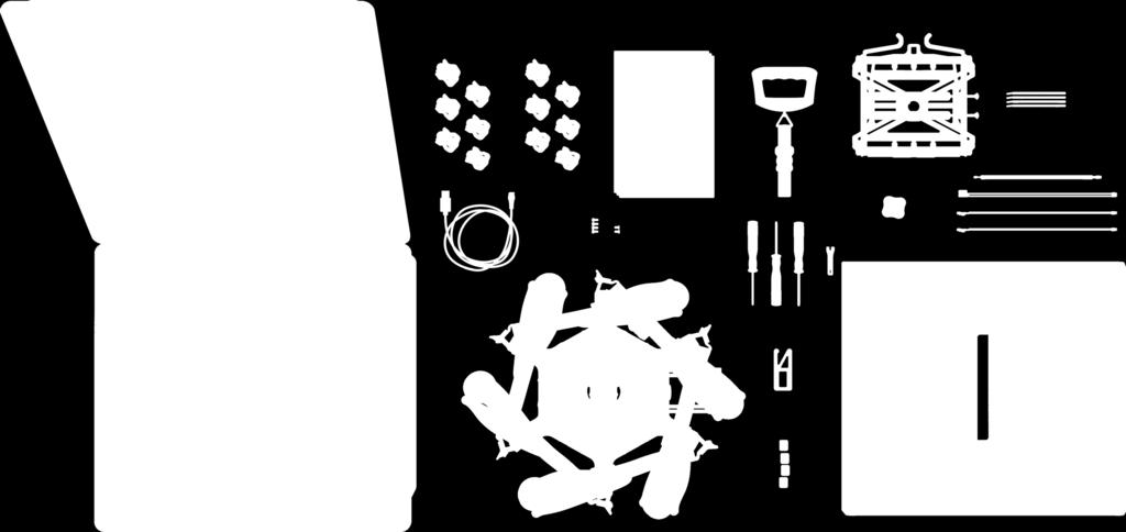
13 UNBOXING ALTA 6 1. Case 2. ALTA 6 Aircraft 3. Case Lid Foam 4. Isolator Cartridges a. (6) Teal (Installed) b. (6) Black c. (6) Red 5. Documentation 6. Electronic Luggage Scale 7. USB-Futaba Power Cable 8. Inverted Landing Gear 9. Antenna Tubes 10. FPV Cables a. Skyzone/BOSCAM Transmitter b. ImmersionRC/Fat Shark Transmitter c. BOSCAM Micro Transmitter d. Ready Made RC Camera 11. Fasteners a. (4) M3 8 Socket Head for Toad In The Hole Male Adapter b. (2) M3 6 Flat Head for Accessory Mount 12. Toad In The Hole Male Adapter mm Wrench 14. Hex Drivers (1.5mm, 2.0mm, 2.5mm) 15. Accessory Mount 16. Double-Sided Tape SETUP GUIDE 13
14 14
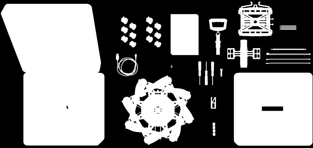
15 UNBOXING ALTA 8 1. Case 2. ALTA 8 Aircraft 3. Case Lid Foam 4. Isolator Cartridges a. (6) Teal (Installed) b. (6) Black c. (6) Red 5. Documentation 6. Electronic Luggage Scale 7. USB-Futaba Power Cable 8. Inverted Landing Gear 9. Antenna Tubes 10. FPV Cables a. Skyzone/BOSCAM Transmitter b. ImmersionRC/Fat Shark Transmitter c. BOSCAM Micro Transmitter d. Ready Made RC Camera 11. (2) M3 x 6 Flat Head for Accessory Mount 12. Quick Release Battery Tray (Installed) mm Wrench 14. Hex Drivers (1.5mm, 2.0mm, 2.5mm) 15. Accessory Mount 16. Double-Sided Tape SETUP GUIDE 15
16 WEIGHT LIMITATIONS As altitude and temperature increase, the density of the air decreases. Consequently, ALTA s thrust will decrease. The following tables describe maximum gross weight limits with respect to altitude and temperature for both ALTA 6 and ALTA 8 models. ALTA 6 0ºC 10ºC 20ºC 30ºC 40ºC Press Alt Ft Maximum Gross Weight (lb) Maximum Gross Weight (kg) Maximum Gross Weight (lb) Maximum Gross Weight (kg) Maximum Gross Weight (lb) Maximum Gross Weight (kg) Maximum Gross Weight (lb) Maximum Gross Weight (kg) Maximum Gross Weight (lb) Maximum Gross Weight (kg) S.L
17 WEIGHT LIMITATIONS (CONTINUED) ALTA 8 0ºC 10ºC 20ºC 30ºC 40ºC Press Alt Ft Maximum Gross Weight (lb) Maximum Gross Weight (kg) Maximum Gross Weight (lb) Maximum Gross Weight (kg) Maximum Gross Weight (lb) Maximum Gross Weight (kg) Maximum Gross Weight (lb) Maximum Gross Weight (kg) Maximum Gross Weight (lb) Maximum Gross Weight (kg) S.L SETUP GUIDE 17
18 DISARM SAFETY SWITCH The Disarm Safety Switch aids in preventing accidental motor disarming while the ALTA is in flight and in manual mode. It may be mapped to either a two-position or three-position switch. To set up the Lockout Switch, refer to the Mapping Channels section or the ALTA Aircraft Flight Manual. 3-POSITION SWITCH FUNCTION 1 On - Disarming is not possible 2 Off - Disarming is possible 3 Off - Disarming is possible 2-POSITION SWITCH FUNCTION 1 On - Disarming is not possible 2 Off - Disarming is possible 18
19 CONTROL MODES ALTA has three primary flight control modes: Manual Mode, Height Mode, and Position Mode. They are selected with the Mode Switch. ALTA also has two emergency control modes, Return-To-Home and Autoland, which are available only during certain situations. For additional information, refer to the sub-section associated with each emergency control mode in the AFM. MANUAL MODE In Manual Mode, ALTA will only stabilize its attitude. At neutral control input (middle pitch and roll stick position), ALTA will attempt to remain level. Throttle control is direct. CAUTION Always neutralize control inputs when switching between control modes. NOTE ALTA s emergency control modes are for emergency use only. Do not test or use emergency control modes in normal flight conditions. HEIGHT MODE Height Mode changes the throttle stick behavior to command climb and descent rates. The higher the throttle stick position, the faster ALTA will climb. Conversely, the lower the throttle stick position, the faster ALTA will descend. When the throttle stick is centered, ALTA will enter Height Hold. In Height Hold, ALTA will maintain a target altitude and try to correct for drift. If a disturbance moves ALTA away from this target altitude, ALTA will climb or descend to return to the target altitude. SETUP GUIDE 19
20 CONTROL MODES [CONTINUED] POSITION MODE Position Mode changes the pitch/roll stick behavior to command ground speeds. Pitch and roll stick deflection will command fore/ aft and left/right ground speeds respectively. Controlling altitude in Position Mode is the same as in Height Mode. With pitch and roll controls centered, ALTA will enter Position Hold. In Position Hold, ALTA will maintain its position over a given point on the ground and correct for disturbances. Position Mode requires a strong GPS signal. If a weak signal is present, ALTA will not enter Position Mode, and if the GPS signal degrades while in Position Mode, ALTA will automatically revert to Manual Mode. RETURN-TO-HOME Return-To-Home (RTH) Mode will command ALTA to fly back to the starting point of the flight or the last defined Home Point. When ALTA first acquires a GPS position, it sets this as the Home Point of the flight. The Home Switch on your radio controller can also be used to set a new Home Point. See Channel Mapping in the AFM for more information on setting up the Home Switch. RTH can be initiated manually by the Home Switch or be initiated with an Loss of Signal (LOS) event. When initiated with the Home Switch, ALTA will fly back to the Home Point, and the pilot will maintain control of ALTA s altitude the entire time. ALTA will not autoland if adequate signal is detected. The pilot can cancel the RTH procedure by commanding a pitch or roll command. During an LOS event, ALTA will first check its current altitude against Safe Height. If it is lower, it will climb to Safe Height, and if ALTA is above Safe Height, it will remain at its current altitude. Next, ALTA will fly back to the home position at the RTH Speed set in the ALTA App. Finally, upon reaching the home position, ALTA will begin Autoland. AUTOLAND The Autoland function will command ALTA to hover for 10 seconds and will then land in place. If ALTA is above the app-configurable Safe Height setting, ALTA will first descend to it at the Maximum Descent Rate. After reaching this height, ALTA s descent will slow to the Autoland Descent Rate. Autoland will only initiate if one of the following conditions is met: During Loss of Signal (LOS) if Autoland is selected as the LOS event in the ALTA app At the end of a LOS Return-to-Home event Battery exhaustion while flying in Height or Position modes only CAUTION Flight using Position Mode in areas of degraded GPS signal, such as near buildings or under dense tree cover, is not recommended. The reversion to Manual Mode can sometimes cause abrupt changes in flight behavior. 20
21 RADIO LOSS OF SIGNAL Return To Home SAFE HEIGHT IS USER DEFINED ALTA APP > CONFIGURATIONS > SAFETY > SAFE HEIGHT SETUP GUIDE 21
22 STATUS LIGHT The rear-facing Status Light shows the status of ALTA as it boots, arms and flies. The following table shows the different meanings of the light in the various flight phases. FLIGHT PHASE LIGHT COLOR MEANING BOOTING Flashing Red + White Flight controller is booting STANDBY Flashing White Flashing Red Flight controller is running and ready to arm Flight controller is running and not ready to arm Solid Red Flight controller boot unsuccessful ARMED Off Ready for flight FLIGHT - ALL MODES Solid Red Flight critical alarm- Land immediately! FLIGHT - MANUAL MODE FLIGHT - HEIGHT MODE Off Solid White Off Slow Flashing White Nominal flight status No errors Outside user-defined range, height or speed limits Nominal flight status Height Hold inactive Height Hold active Flashing Red Flight critical alarm- Land immediately! FLIGHT - POSITION MODE Off Slow Flashing White Fast Flashing White Nominal flight status Height Hold inactive Position Hold inactive Height Hold or Position Hold active Height Hold and Position Hold active Flashing Red Flight critical alarm- Land immediately! 22
23 ALARMS ALTA will notify the pilot of critical alarms using the Status Light. These alarms indicate a serious issue has been observed in the behavior of the ALTA that, if not acted upon immediately, can cause loss of control. Never continue a flight when ALTA indicates an alarm. WARNING If ALTA displays an alarm, land immediately. During an alarm, the Status Light will turn red. SETUP GUIDE 23
 during other flight phases.")

24 ORIENTATION LIGHTS The boom-end mounted Orientation Lights indicate both the orientation of ALTA in flight and the status of the individual motor Electronic Speed Controllers (ESCs) during other flight phases. The following table shows the different meanings of the light colors in the various flight phases. FLIGHT PHASE LIGHT COLOR MEANING BOOTING Blue ESC booting STANDBY Flashing green ESC booted normally ARMED User-defined Nominal status FLIGHT User-defined Nominal status FIRMWARE UPDATE Blue then yellow ESC firmware is updating ALTA 6 BOTTOM VIEW ALTA 8 BOTTOM VIEW 24
25 COMPASS CALIBRATION ALTA features a highly sensitive 3-axis magnetometer that measures the earth s magnetic field to infer heading. Occasionally, the compass will require calibration, especially when traveling between different geographic locations. TO PERFORM A COMPASS CALIBRATION: 1. Secure a battery onto ALTA (see page 18-19) 2. Plug in the battery 3. Open the ALTA App 4. Select Configurations > More > Compass 5. Under Calibration, select Start Manual 6. Follow the on-screen instructions WARNING Verify ALTA is disarmed prior to performing a compass calibration. To ensure ALTA does not arm, remove the Configuration Jumper, set the mode switch to Height or Position, or set the home switch to Set New Home Position. NOTE It is recommended to use two people to perform the compass calibration as it requires handling and rotating ALTA. Perform calibration without a payload attached. NOTE Ensure a microsd card is installed in the GPS/compass module prior to performing compass calibration. SETUP GUIDE 25
26 ARMING AND STARTING ALTA MOTORS TO ARM ALTA 1. Ensure ALTA is powered on and is in Standby Mode 2. Select Manual Mode using the radio controller s Mode Switch 3. Set the Home Switch to the middle position 4. Hold full low throttle and full left yaw 5. Ensure Status Light extinguishes and Orientation Lights change to the colors defined in the app NOTE Refer to the radio controller s documentation for help determining the controller mode (1 or 2). 4 MODE L R POSITION HEIGHT MANUAL RTH OFF L MODE 01 R 26
27 TO START ALTA MOTORS 1. Ensure ALTA is armed 2. Hold full low throttle and full right yaw 3. Ensure ALTA motors spin up WARNING Always check the ALTA and its components prior to operation. Always maintain a safe distance from the ALTA when in use. Never attempt to touch the ALTA when the propellers are moving. TO STOP ALTA MOTORS AND DISARM 1. Set the Disarm Safety Switch to Off 2. Ensure Mode Switch is set to Manual Mode 3. Hold full low throttle and full left yaw 4. Ensure ALTA Status Light flashes white and Orientation Lights flash green WARNING Motors can be disabled in flight if the disarming procedure is followed. CAUTION Do not attempt to disarm motors in Height or Position Modes. 2 MODE MODE 02 L R ON L R OFF MODE 01 2 MODE 01 L R POSITION HEIGHT MANUAL L R SETUP GUIDE 27
28 SETTING HOVER THROTTLE Hover Throttle is an app-configurable parameter that adjusts ALTA s thrust at center throttle stick and ensures ALTA does not climb or descend at the center stick position while flying in Manual Mode. A Hover Throttle setting that is too high or too low can cause ALTA to climb or descend when switching between Manual Mode and Height Mode. Adjust the Hover Throttle setting by entering a stable hover in Manual Mode. Note the stick position, or have an assistant view the radio chart in the ALTA App to determine stick position. If ALTA hovers with the stick below neutral, decrease the Hover Throttle until ALTA hovers with neutral stick input. If ALTA hovers with the stick above neutral, increase the Hover Throttle until ALTA hovers with neutral stick input. NOTE Hover Throttle will need to be adjusted when changing the overall weight of the system, or when moving between very different elevations. NOTE The ALTA App does not allow Hover Throttle adjustments while ALTA is flying. IF THEN COMPLETE Bring ALTA to a hover IF THEN DECREASE Hover Throttle IF THEN INCREASE Hover Throttle 28
29 TUNING ALTA ALTA models come pre-tuned for a wide variety of payloads and flying conditions. Generally, additional tuning is not required to fly ALTA, and additional tuning will only need to take place if more customization of control feel is desired. For more information on tuning parameters, refer to the Aircraft Flight Manual for your ALTA model. WARNING Tuning can change the fundamental flying characteristics of ALTA. It is possible for ALTA to become unstable or even uncontrollable if values are set too high or too low. Only change tuning parameters in small increments and with caution. Always test new tuning configurations in open areas away from people or obstacles. SETUP GUIDE 29


30 UNFOLDING ALTA 1. Remove ALTA from case 2. Fold down all boom retention clips 3. Open ALTA booms 4. Snap shut all boom latches until they click 5. Visually confirm all latches are seated properly 6. Remove prop protectors


31 FOLDING ALTA 1. Secure props with prop protectors 2. Unlatch all booms 3. Close ALTA booms 4. Fold up all boom retention clips to secure booms SETUP GUIDE 31


32 INSTALLING A RADIO RECEIVER ON ALTA Locate the noted closeout panels used for receiver installation (between booms 1 & 2 and 4 & 5) 2. Remove side closeout panel with radio wires using a 1.5mm hex driver 3. Identify required wire 4. Feed wire through grommet 5. Replace side closeout panel 6. Plug in receiver/satellite to wire per the radio manufacturer s installation instructions NOTE Refer to the Aircraft Flight Manual for Futaba voltage telemetry installation instructions. Telemetry is only available between booms 1 & S.BUS/S.BUS2 PPM DSM2/DSMX 32


")
33 BINDING A RADIO RECEIVER 7. Attach receiver/satellite to exterior using the provided double sided tape: a. Futaba & PPM receiver b. Spektrum/JR 8. For Futaba receivers, feed antenna wires into antenna tubes and zip tie to noted mounting location 9. Repeat 1-7 on opposite side for dual receivers (only applies to Futaba and Spektrum/JR) Refer to the instructions provided with your radio controller to complete the binding process. For Spektrum/JR radios, a receiver is required to bind the satellites to a radio controller. 7a 7b 8 SETUP GUIDE 33
 2.")
 5.")
34 INSTALLING A RADIO RECEIVER ON ALTA 8 1 For Futaba and PPM receivers: 1. Locate the noted closeout panels used for Futaba receiver installation (between booms 2 & 3 and 6 & 7) 2. Remove side closeout panel using a 2.0mm hex driver 3. Plug signal wire into receiver 4. If using telemetry, plug telemetry wire in (refer to ALTA 8 Aircraft Flight Manual for instructions) 5. Feed receiver antenna into lower antenna tube NOTE Refer to the Aircraft Flight Manual for Futaba voltage telemetry installation instructions


35 BINDING A RADIO RECEIVER 6. Secure receiver using the provided double sided tape to inside of receiver housing 7. Reattach closeout panel 8. Route antenna wires into the two antenna tubes below ALTA 8 chassis 9. Repeat steps 1-8 for dual receivers (only applies to Futaba receivers) Refer to the instructions provided with your radio controller to complete the binding process. For Spektrum/JR radios, a receiver is required to bind the satellites to a radio controller SETUP GUIDE 35
 2.")

36 INSTALLING A RADIO RECEIVER ON ALTA 8 (CONTINUED) For Spektrum/JR: 1. Located the noted closeout panels used for Spektrum/JR receiver installation (between booms 3 & 4 and 7 & 8) 2. Remove side closeout panel using a 2.0mm hex driver. 3. Feed signal cable through panel grommet 4. Reattach closeout panel 5. Plug in receiver/satellite into signal cable 6. Attach receiver/satellite to exterior using double sided tape 7. Repeat steps 1-6 for dual receivers

37 CONFIGURATION JUMPER A small jumper is used to prevent motor operation while configuring radio mapping parameters. With the jumper in place, the motors may operate, but channel mapping is prevented. With the jumper removed, channel mapping may take place, but the motors will be turned off. 1. Locate the closeout panel where the jumper is installed a. ALTA 6 between booms 5 & 6 b. ALTA 8 between booms 5 & 6 2. Remove the side closeout panel with the jumper using a 1.5mm (ALTA 6) or a 2.0mm (ALTA 8) hex driver 3. Remove or replace the jumper 4. Reattach the closeout panel 1a 1b 2 3 SETUP GUIDE 37
38 ALTA APP The ALTA App is used to configure ALTA parameters and to monitor ALTA s status during flight. To download the ALTA App, search for Freefly ALTA in the App Store or on Google Play. NOTE When making configuration changes with the ALTA App, wait three seconds before closing the app for changes to be saved automatically. 38
39 MAPPING CHANNELS To map channels, use the ALTA App. For complete information on channel mapping, please refer to the ALTA Aircraft Flight Manual. 1. Remove the Configuration Jumper 2. Power ALTA using a battery pack or by plugging in the included USB-Futaba cable into an available port on a Futaba receiver 3. Open the ALTA App and connect to ALTA 4. Open Configurations > Radio 5. Open each ALTA function and adjust the channel to the desired channel number, and use the toggle to invert the orientation of a control RADIO SETUP ADJUSTMENTS CONTROLLER FUTABA CHANNEL MAPPING PITCH ROLL YAW WARNING Always ensure the Configuration Jumper is removed prior to adjusting radio settings to prevent unintentional motor starts. WARNING Ensure proper channel mapping prior to flight. Incorrect mapping can lead to immediate loss of control. 6. Ensure proper channel selection by moving the control input on the radio controller and verifying the displayed graph in the ALTA App responds correctly THROTTLE MODE HOME SWITCH ONCE CHANNELS ARE MAPPED 7. Remove the battery or USB-Futaba cable from ALTA 8. Replace the Configuration Jumper VELOCITY CLAMP CLIMB RATE CLAMP ARM ENABLE SWITCH SETUP GUIDE 39
40 FAILSAFE AND LOSS OF SIGNAL FUTABA S.BUS AND SPEKTRUM/JR DSM When using Futaba receivers with S.Bus or S.Bus2, or using Spektrum or JR receiver satellites with DSM2 or DSMX, the Synapse Flight Controller can detect signal strength and a loss of signal event. Setting failsafes in the receiver is not necessary, as failsafe behavior is set in the ALTA App. The radio s failsafe settings will not be used. WARNING Improperly set failsafe settings on PPM radio receivers can cause unexpected flight behaviors if ALTA loses radio control signal. After setting radio failsafe settings, ensure they are correct by viewing the channel mapping parameters in the radio configuration screen in the ALTA App, or viewing radio charts in the ALTA App. Ensure that the radio commands behave as expected when the radio controller is powered off. PPM RECEIVERS When using a receiver with a PPM output signal, the Synapse Flight Controller will not automatically detect loss of signal and will follow the radio controller failsafe commands typically set during the bind process. Refer to your radio controller manual for information on setting up failsafes. 40
41 FREEFLY RECOMMENDS THE FOLLOWING FAILSAFE SETTINGS: 1. Throttle: Neutral 2. Pitch/Roll/Yaw: Neutral 3. Flight Mode Switch: Position Mode 4. Home Switch: Return to Home POSITION HEIGHT MANUAL R.T.H. LEFT STICK RIGHT STICK SETUP GUIDE 41


42 INSTALLING A BATTERY GROUNDVIEW 1. Place battery retention strap studs at the appropriate height for battery packs 2. Adjust battery stops to fit battery packs 3. Attach the single-hole end of the battery retention straps to the studs 4. Place battery packs on battery tray below handle 5. Tension and secure battery retention straps. NOTE For ALTA 8, use the included Quick Release Battery Tray for battery mounting. CAUTION Do not install batteries on the lower battery tray if a Toad adapter is also installed. Either remove the Toad adapter or use the Quick Release Battery Tray. WARNING CAUTION See warning and cautions on page


43 SKYVIEW 1. Pinch the battery tray handles and slide to remove it from landing gear. 2. Attach the single-hole ends of the battery retention straps to the studs on the battery tray 3. Place battery packs onto battery tray 4. Tension and secure battery retention straps 5. Slide tray with battery packs back into landing gear until it latches in place. 6. Ensure tray and battery packs are secure WARNING CAUTION See warning and cautions on page SETUP GUIDE 43
44 WARNING Always secure battery packs with both battery retention straps. CAUTION When plugging in battery packs, ensure the polarity is correct. Positive is indicated by a red power lead, and negative/ground is indicated by a black power lead. Reversing polarity will damage ALTA s electronics. CAUTION Ensure both battery packs are at a similar state of charge (a full pack voltage difference less than 0.5V) prior to connecting them to ALTA. Plugging in two dissimilarly charged packs could cause one pack to rapidly discharge into the other and damage the batteries or cause a battery fire. CAUTION Only use packs that are identical in their capacity and at a similar condition. Using a pack with another that is larger, or has many more cycles, can damage the battery packs. 44

45 SETUP GUIDE 45
 a. Attach landing gear b. Install TITH receiver on MōVI 2. Connect MōVI to bottom Toad 2 46 WWW.FREEFLYSYSTEMS.COM")
46 ATTACHING A MōVI A MōVI can be attached to either the top or bottom of the ALTA via the Freefly Toad In The Hole (TITH) Quick Release. ALTA comes pre-configured for bottom mounting a MōVI. GROUNDVIEW 1. Prepare your MōVI for GroundView flight (see MōVI manual) a. Attach landing gear b. Install TITH receiver on MōVI 2. Connect MōVI to bottom Toad


47 SKYVIEW 1. Prepare your MōVI for SkyView flight a. Remove landing gear (see MōVI manual) CAUTION Top mounting is not supported by the MōVI M10. b. Install TITH receiver on MōVI (see MōVI manual) 2. Connect and secure the supplied inverted landing gear to the bottom Toad 3. Prepare your ALTA for SkyView Flight For ALTA 6 a. Remove the four flathead M3 6 bolts that secure the top handle b. Attach the supplied Toad to the top plate using the four M3 8 bolts provided For ALTA 8 c. Remove Quick Release Battery Tray 4 4. Connect MōVI to the top Toad 3a 3b 3c 2 SETUP GUIDE 47
48 MōVI is a registered trademark in the U.S. Pat. & Tm. Office. FREEFLY, the wing logo, and ALTA, ALTA 6 and ALTA 8 are trademarks of Freefly Systems Inc. Apple and the Apple logo are trademarks of Apple Inc., registered in the U.S. and other countries. App Store is a service mark of Apple Inc. Google Play is a trademark of Google, Inc
USER MANUAL REVISION A
 USER MANUAL REVISION A 07.24.2015 REVISION HISTORY REVISION DATE DESCRIPTION A July 2015 Initial Release ALTA USER MANUAL PART NUMBER: 770-00042 CONTENTS 2 Revision History 3 Contents 5 ALTA OVERVIEW 6
A3 Pro INSTRUCTION MANUAL. Oct 25, 2017 Revision IMPORTANT NOTES
 A3 Pro INSTRUCTION MANUAL Oct 25, 2017 Revision IMPORTANT NOTES 1. Radio controlled (R/C) models are not toys! The propellers rotate at high speed and pose potential risk. They may cause severe injury
Caution Notes. Features. Specifications. Installation. A3-L 3-axis Gyro User Manual V1.0
 Caution Notes Thank you for choosing our products. If any difficulties are encountered while setting up or operating it, please consult this manual first. For further help, please don t hesitate to contact
DIY KITS FRAME KIT. Thank you for purchasing a 3DR Y6 DIY Kit!
 DIY KITS Y6 FRAME KIT Thank you for purchasing a 3DR Y6 DIY Kit! These instructions will guide you through assembling and wiring your new autonomous multicopter. CONTENTS Your 3DR Y6 Kit contains: 35 mm
FSCTD Dual Back to Back Flat Screen Ceiling Mount
 Page 1 of 6 FSCTD Dual Back to Back Flat Screen Ceiling Mount The FSCTD Dual Back to Back Flat Screen Ceiling Mount is designed to suspend a monitor from a single flange mounted to structure in the ceiling.
Xtreme Power Systems
 Xtreme Power Systems XtremeLink NANO RECEIVER Installation And Usage Manual XtremeLink is a registered trademark of Xtreme Power Systems, LLC. Firmware v 1.9 Manual v 1.9 Revision Date: November 11 th,
Introduction. Overview. Outputs Normal model 4 Delta wing (Elevon) & Flying wing & V-tail 4. Rx states
 & Flying wing & V-tail 4. Rx states") Introduction Thank you for purchasing FrSky S6R/S8R (SxR instead in this manual) multi-function telemetry receiver. Equipped with build-in 3-axis gyroscope and accelerometer, SxR supports various functions.
Introduction Thank you for purchasing FrSky S6R/S8R (SxR instead in this manual) multi-function telemetry receiver. Equipped with build-in 3-axis gyroscope and accelerometer, SxR supports various functions.
ARKBIRD-Tiny Product Features:
 ARKBIRD-Tiny Product Features: ARKBIRD System is a high-accuracy autopilot designed for fixed-wing, which has capability of auto-balancing to ease the manipulation while flying. 1. Function all in one
Manual for Hyperion Receivers 1. Binding Step 1. Power up the receiver in bind mode
 - This is not a Horizon Hobbies DSM2, DSMX product, and is not manufactured or endorsed by Horizon Hobbies LLC. DSM2, and DSMX are registered trademarks of Horizon Hobbies LLC. Manual for Hyperion Receivers
LC200DS2 Double Stud Dual Articulating Wall Mount for Flat Panel Screens up to 32" with up to 200mm x 200mm VESA Mounting Patterns
 LC200DS2 Double Stud Dual Articulating Wall Mount for Flat Panel Screens up to 32" with up to 200mm x 200mm VESA Mounting Patterns Multi-position triple pivoting arms allows you to position the monitor
User Manual Version 1.0
 1 Thank you for purchasing our products. The A3 Pro SE controller is the updated version of A3 Pro. After a fully improvement and optimization of hardware and software, we make it lighter, smaller and
THE HUBSAN X4 DESIRE
 Ages 14+ READ THE INSTRUCTION MANUAL CAREFULLY PLEASE VISIT WWW.HUBSAN TO UPGRADE THE HUBSAN X4 DESIRE ITEM NO.: H502E ARM/DISARM MOTORS, SEE PAGE 06 RTH FUNCTION, SEE PAGE 09 COMPASS CALIBRATION, SEE
PART #MSP-DCCPPWS Plasma Wall Swing-Out (PWS) Wall Mount
 Wall Mount") I N S T R U C T I O N M A N U A L PART # Plasma Wall Swing-Out (PWS) Wall Mount The wall mount is a rugged, versatile, and installer-friendly solution to unique display mounting requirements. With the
I N S T R U C T I O N M A N U A L PART # Plasma Wall Swing-Out (PWS) Wall Mount The wall mount is a rugged, versatile, and installer-friendly solution to unique display mounting requirements. With the
Babyhawk User Manual
 Babyhawk User Manual Thanks for purchasing the Babyhawk. Please follow the instruction manual to install and configure your Babyhawk. After completing the instruction manual, use the configurator GUI to
LC200DS1 Double Stud Articulating Wall Mount for Flat Panel Screens up to 32" with up to 200mm x 200mm VESA Mounting Patterns
 Page 1 of 6 LC200DS1 Double Stud Articulating Wall Mount for Flat Panel Screens up to 32" with up to 200mm x 200mm VESA Mounting Patterns A multi-position dual articulating arm for flat screens up to 60
HM4050 AVCS HEADING LOCK GYRO
 INCLUDES HM4050 gyro with connectors Foam adhesive tape Manual HM4050 AVCS HEADING LOCK GYRO FEATURES AVCS (Angular Vector Control System) Small size Lightweight Able to operate in Heading Hold as well
Fletcher F-3000 / F-3100 Accessory Laser Kit
 Fletcher F-3000 / F-3100 Accessory Laser Kit Shown Assembled on F-3000 Machine Product Warranty The Fletcher-Terry Company warrants the product purchased to be free from defects in parts and workmanship
Copyright Graupner/SJ GmbH. Manual. Vector Unit / Vector Unit Extreme 2 channel HoTT 2,4 GHz receiver/servo/speed controller unit No No.
 Copyright Graupner/SJ GmbH EN Manual Vector Unit / Vector Unit Extreme 2 channel HoTT 2,4 GHz receiver/servo/speed controller unit No. 34002 No. 34003 Index Introduction... 4 Service Center... 4 Intended
SRD250. Storm Racing Drone For 250/250Pro V2 USER MANUAL V3. HeliPal.com. All Rights Reserved
 SRD250 Storm Racing Drone For 250/250Pro V2 USER MANUAL V3 1 DISCLAIMER Please read this disclaimer carefully before using this product. This product is a hobby with motors but not a toy which is not suitable
Instructions for Crack Series / Superior RX
 Instructions for Crack Series / Superior RX DSMX and DSM2 Compatibility Superior Rx receivers work with both DSM2 and DSMX versions. DSMX is a development of the earlier DSM2 specification that includes
B O T- S e r i e s B u i l d M a n u a l. Droidworx L t d N e w Z e a l a n d
 B O T- S e r i e s B u i l d M a n u a l Droidworx L t d N e w Z e a l a n d 1 B O T- S e r i e s B u i l d M a n u a l 1.0 FLIGHT OPERATION AND SAFETY 4 Operation and Safety 6 Pre-Flight Safety Check
Black Knight. Black Knight 210/250 FPV Quadcopter Manual
 Black Knight Black Knight 210/250 FPV Quadcopter Manual Version: Naze V6 V1.1 www.spedix-rc.com WARNING For age 14+ only. Rotating propellers may cause serious injury and damages! Do not install propellers
STORM Racing Drone Type-A USER MANUAL V1.1
 STORM Racing Drone Type-A USER MANUAL V1.1 1 DISCLAMIER Please read this disclaimer carefully before using this product. This product is a hobby with motor but not toy which is not suitable for people
INSTALLATION INSTRUCTIONS Small Flat Panel Height-Adjustable, Extended Pitch Swing Arm Wall Mount Model KWE-110
 INSTALLATION INSTRUCTIONS Small Flat Panel Height-Adjustable, Extended Pitch Swing Arm Wall Mount Model KWE-110 The KWE dual swing arm wall mount is designed to provide a broad range of viewing for Small
Modified Spektrum DM9 Module for Use with Futaba 8FG, 12FG, 14SG and 18SZ Transmitters INSTRUCTIONS
 Modified Spektrum DM9 Module for Use with Futaba 8FG, 12FG, 14SG and 18SZ Transmitters INSTRUCTIONS Ivan Cankov (ivanc on RCGroups) Modified Spektrum DM9 Module for Use with Futaba 8FG, 12FG, 14SG and
LC200WT Security Wall Mount with Tilt for up to 32" Flat Screens
 Page 1 of 6 The LC200WT Security Wall Mount with Tilt is designed to secure up to a 32" flat panel monitor to the wall while still allowing the monitor to tilt. The VESA mounting patterns on the front
Thank you for purchasing this DJI product. Please strictly follow these steps to mount and connect this system on
 NAZA-M LITE User Manual V 1.00 2013.05.28 Revision For Firmware Version V1.00 & Assistant Software Version V1.00 Thank you for purchasing this DJI product. Please strictly follow these steps to mount and
LC6X4WTM Security Wall Mount with Tilt for up to 60" Flat Screens with VESA 600mm x 400mm or less
 Page 1 of 6 The LC6X4WTM Security Wall Mount with Tilt is designed to secure a flat screen, up to a 60", to the wall while still allowing the monitor to tilt. The VESA mounting patterns on the front of
NAZA-M Quick Start Guide V 1.0
 NAZA-M Quick Start Guide V 1.0 Thank you for purchasing this DJI product. Please regularly visit the NAZA-M web page at www.dji-innovations.com. This page is updated regularly. Any technical updates and
Installation & Operation Manual SAGA1-K Series Industrial Radio Remote Control
 Installation & Operation Manual SAGA1-K Series Industrial Radio Remote Control Gain Electronic Co. Ltd. Table Of Contents Safety Considerations ------------------------------------------------------------2
Multi-rotor flight stabilization & Autopilot System Installation & Operation Guide. Guilin Feiyu Electronic Technology Co., Ltd
 Rev: 5 th July 2011 FEIYU TECH FY-91Q DREAMCATCHER Multi-rotor flight stabilization & Autopilot System Installation & Operation Guide Guilin Feiyu Electronic Technology Co., Ltd Rm. B305, Innovation Building,
STORM Drone 4 Flying Platform (V2.0) USER MANUAL
 USER MANUAL") STORM Drone 4 Flying Platform (V2.0) USER MANUAL 1 DISCLAMIER Please read this disclaimer carefully before using this product. This product is a hobby with motor but not toy which is not suitable for people
STORM Drone 4 Flying Platform (V2.0) USER MANUAL 1 DISCLAMIER Please read this disclaimer carefully before using this product. This product is a hobby with motor but not toy which is not suitable for people
Revision For Firmware Version V3.30 or above & Adjusting-parameter software Version V1.40 or above
 T1 User Manual V1.4 2016.07.20 Revision For Firmware Version V3.30 or above & Adjusting-parameter software Version V1.40 or above Please strictly follow these steps to mount and use this product, as well
Articulating TV/Monitor Grommet/Clamp Desk Mount Model: DE300S (Butterfly Series)
") t Articulating TV/Monitor Grommet/Clamp Desk Mount Model: DE300S (Butterfly Series) Instruction Manual Images may different from actual product Disclaimer It is Dyconn s intention to have all the correct
t Articulating TV/Monitor Grommet/Clamp Desk Mount Model: DE300S (Butterfly Series) Instruction Manual Images may different from actual product Disclaimer It is Dyconn s intention to have all the correct
X10+ Channel Expander (V2)
") Xtreme Power Systems X10+ Channel Expander (V2) Installation And Usage Manual Supports: XtremeLink RFU and Nano receivers Futaba SBUS and SBUS2 receivers Spektrum DSM2/DSMX satellite receivers JR DMSS
Xtreme Power Systems X10+ Channel Expander (V2) Installation And Usage Manual Supports: XtremeLink RFU and Nano receivers Futaba SBUS and SBUS2 receivers Spektrum DSM2/DSMX satellite receivers JR DMSS
A3 SUPER 3 INSTRUCTION MANUAL. For Firmware Version 1.0, Data Version 1.0 Oct 25, 2017 Revision.
 A3 SUPER 3 INSTRUCTION MANUAL For Firmware Version 1.0, Data Version 1.0 Oct 25, 2017 Revision support@hobbyeagle.com 1 CONTENTS IMPORTANT NOTES.....3 1. Introduction......4 2. Setup Procedure Overview...5
Caliper Brake WINDCAL 90
 Caliper Brake WINDCAL 90 (i) FORM NO. L-20233-A-0601 In accordance with Nexen s established policy of constant product improvement, the specifications contained in this manual are subject to change without
Ninja 250. Storm Racing Drone With CC3D Controller USER MANUAL V3. HeliPal.com. All Rights Reserved
 Ninja 250 Storm Racing Drone With CC3D Controller USER MANUAL V3 1 DISCLAIMER Please read this disclaimer carefully before using this product. This product is a hobby with motors but not a toy which is
INSTALLATION INSTRUCTIONS Medium Flat Panel Model MSP-SI1
 INSTALLATION INSTRUCTIONS Medium Flat Panel Model MSP-SI1 IMPORTANT! : The MSP-S11 Mount is designed for use with Sharp 45" LCD displays that have a 200mm x 200mm mounting pattern. IMPORTANT! : The mount
Castle Multi-Rotor ESC Series User Guide
 Castle Multi-Rotor ESC Series User Guide This user guide is applicable to all models of Castle Multi-Rotor ESC. Important Warnings Castle Creations is not responsible for your use of this product or for
EXMITTER -- Professional Remote Control Products Expert
 EXMITTER -- Professional Remote Control Products Expert WARNING The following terms are used throughout the product literature to indicate various levels of potential harm when operating this product.
Detrum GAVIN-8C Transmitter
 Motion RC Supplemental Guide for the Detrum GAVIN-8C Transmitter Version 1.0 Contents Review the Transmitter s Controls... 1 Review the Home Screen... 2 Power the Transmitter... 3 Calibrate the Transmitter...
WRM-10 TM TRANSFORMER WINDING RESISTANCE METER
 WRM-10 TM TRANSFORMER WINDING RESISTANCE METER USER S MANUAL Vanguard Instruments Company, Inc. 1520 S. Hellman Ave. Ontario, California 91761, USA TEL: (909) 923-9390 FAX: (909) 923-9391 June 2009 Revision
Installing the Hughes BGAN Remote Antenna
 Installing the Hughes BGAN Remote Antenna Product description BGAN Remote Antenna The Hughes BGAN Remote Antenna (HNS Part No. 9501286-0001) is designed to be permanently installed with the Basic Fixed
OWNER S MANUAL: Adjustable Height Wall Rack
 OWNER S MANUAL: Adjustable Height Wall Rack Keep this information for further reference. Thank you for purchasing a NavePoint product. Please examine the product for any damaged parts. If any part is damaged
FOXTECH Nimbus VTOL. User Manual V1.1
 FOXTECH Nimbus VTOL User Manual V1.1 2018.01 Contents Specifications Basic Theory Introduction Setup and Calibration Assembly Control Surface Calibration Compass and Airspeed Calibration Test Flight Autopilot
28in Super EVA Foam. F-22 Raptor Kit. Specifications. Wingspan: 27.5in (700mm) Length: 38.3in (975mm) Flying Weight: Approx. 1.
 Length: 38.3in (975mm) Flying Weight: Approx. 1.") 28in Super EVA Foam F-22 Raptor Kit Specifications Wingspan: 27.5in (700mm) Length: 38.3in (975mm) Flying Weight: Approx. 1.2lbs (530g) Dear Customer, Congratulations on your purchase of 28in F22 Raptor
28in Super EVA Foam F-22 Raptor Kit Specifications Wingspan: 27.5in (700mm) Length: 38.3in (975mm) Flying Weight: Approx. 1.2lbs (530g) Dear Customer, Congratulations on your purchase of 28in F22 Raptor
Scorpion HX User Manual R/C Version
 Table of Contents Features...3 Connections...5 Setup...5 Setup Complete...10 Status Codes...11 Mounting your Scorpion...12 Notes on PCM radios...12 Service and Support...13 Limitations and Warrantees...13
Universal Projector Ceiling Mount Model: DPM-45
 Universal Projector Ceiling Mount Model: DPM-45 Instruction Manual Images may different from actual product Disclaimer It is Dyconn s intention to have all the correct information represented within this
REMOVE REAR OF TX-2S TO INSERT THE 9 VOLT BATTERY.
 P.O Box 578 Casino, NSW, 2470 Australia Phone: International ++614 2902 9083 Australia (04) 2902 9083 Website: http://rcs-rc.com E mail: Info@rcs-rc.com TX-2s Digital Proportional R/C TABLE OF CONTENTS
Acu-Park TM. user s guide Directed Electronics, Inc. Vista, CA N9100T 09-04
 Acu-Park TM user s guide 2004 Directed Electronics, Inc. Vista, CA N9100T 09-04 limited one year warranty Directed Electronics, Inc. (hereinafter "Directed") promises to the original purchaser that this
Copyright Graupner/SJ GmbH. Manual. mz-4 2 channel HoTT 2,4 GHz transmitter No. S1031
 Copyright Graupner/SJ GmbH EN Manual mz-4 2 channel HoTT 2,4 GHz transmitter No. S1031 Index Introduction... 4 Service Centre... 4 Intended use... 5 Package content... 5 Technical Data... 5 Symbols Explication...
IEM 200 R UHF receiver. user manual
 IEM 200 R UHF receiver user manual Musikhaus Thomann Thomann GmbH Hans-Thomann-Straße 1 96138 Burgebrach Germany Telephone: +49 (0) 9546 9223-0 E-mail: info@thomann.de Internet: www.thomann.de 17.11.2015,
Storm Racing Drone SRD370. with DJI Naza Lite or DJI Naza V2 USER MANUAL. HeliPal.com. All Rights Reserved
 Storm Racing Drone SRD370 with DJI Naza Lite or DJI Naza V2 USER MANUAL V6! 1 DISCLAIMER Please read this disclaimer carefully before using this product. This product is a hobby with motors but not a toy
Product Introduction:
 Product Introduction: ARKBIRD-433UHF is a 10-channel module designed for long-distance flight: 1. The advanced code division frequency hopping system (FHSS) produces the only way of frequency hopping sequence
Flight control Set and Kit
 Flight control Set and Kit Quick Start Guide For MegaPirate NG Version 1.2 Thanks for choosing AirStudio flight control electronics. We have created it based on best-in-class software, hardware and our
Sales & Service. JFK - Just For Kids. sasportonline.com. 135 Forestview Road 7879 Will Rogers Blvd.
 Sales & Service sasportonline.com SA Sport (Canada) SA Sport (U.S.A.) 135 Forestview Road 7879 Will Rogers Blvd. P.O. Box 40 Fort Worth, Texas Orillia, Ontario USA 76140 Canada L3V 6H9 Telephone: (705)
Tilting, Swiveling & Rotating Flat Panel Wall Mount
 Tilting, Swiveling & Rotating Flat Panel Wall Mount Model: VXA980TC +5 to -5 +5 to -5 Supports most 0-80 Flat Panel TVs Maximum Weight Capacity: 32 lbs. Supports VESA Sizes up to 600x500 For technical
2015 RIGOL TECHNOLOGIES, INC.
 Service Guide DG000 Series Dual-channel Function/Arbitrary Waveform Generator Oct. 205 TECHNOLOGIES, INC. Guaranty and Declaration Copyright 203 TECHNOLOGIES, INC. All Rights Reserved. Trademark Information
Truss Pitch-Adjustable (TPP) Mount
 Mount") I N S T R U C T I O N M A N U A L Truss Pitch-Adjustable (TPP) Mount The Truss Pitch-Adjustable (TPP) mount is a perfect solution exhibit, retail and digital signage applications. The mount is quick, easy
I N S T R U C T I O N M A N U A L Truss Pitch-Adjustable (TPP) Mount The Truss Pitch-Adjustable (TPP) mount is a perfect solution exhibit, retail and digital signage applications. The mount is quick, easy
User Manual. Smart-UPS On-Line. Uninterruptible Power Supply. Isolation Transformer Models: SURT001 and SURT002
 User Manual Smart-UPS On-Line Uninterruptible Power Supply Isolation Transformer Models: SURT001 and SURT002 Isolation and Step-Down Transformer Models: SURT003 and SURT004 General Information Important
GyroPilot V3. Operator s Manual
 GyroPilot V3 Operator s Manual TABLE OF CONENTS 1 UNPACKING... 3 2 PRODUCT OVERVIEW... 3 3 BEFORE USE... 3 3.1 CHARGING INSTRUCTIONS 3 4 USAGE... 4 4.1 SWITCHING ON 4 4.2 CONNECTIVITY 4 4.3 NORMAL OPERATION
Downwelling Light Sensor 2 (DLS 2) Integration Guide
 Integration Guide") Downwelling Light Sensor 2 (DLS 2) Integration Guide Revision 01, November 2018 Seattle, WA 2018 MicaSense, Inc. Page 1 of 17 Table of Contents Overview and Scope 3 Measurements and Attachment Points 4
Downwelling Light Sensor 2 (DLS 2) Integration Guide Revision 01, November 2018 Seattle, WA 2018 MicaSense, Inc. Page 1 of 17 Table of Contents Overview and Scope 3 Measurements and Attachment Points 4
Assembly Instructions Signature Choral Riser 4-Step Model
 Assembly Instructions Signature Choral Riser 4-Step Model Contents Important User Information...........................2 General...2 Manufacturer...2 Intended Use...2 Warranty...2 Safety Precautions.................................3
Super Sky Surfer 2000 Assembly Instructions
 Super Sky Surfer 2000 Assembly Instructions Note: Plug and Play version of the Sky Surfer comes with fuselage pre-glued and motor/servos installed. If you wish to route antennas or wires through the tail,
DJT RC Transmitter Module 2.4 GHz Two-Way Series
 Manual Rev.0.1-5.05.201 2 made by David LABURTHE dlaburthe@free. fr DJT RC Transmitter Module 2.4 GHz Two-Way Series U S E R ' S G U I D E FrSky Electronic Co., Ltd - No. 1, Huize Road, Wuxi, 21 4081,
YS-S4 Multi-rotor Autopilot User Manual V1.4
 User Manual V1.4 YS-S4 Multi-rotor Autopilot Zero UAV (Beijing) Intelligence Technology Co. Ltd 1 1. In-Box...3 2. Functions... 4 3. Installation... 5 4. Connections...6 4.1 Assembly... 6 4.2 Real connection
Precaution of Safety. Before using this product, check that you have all of the following items. If any items are missing, please contact dealer.
 USER MANUAL 1 2 Content Before using this product, check that you have all of the following items. If any items are missing, please contact dealer. Introduction Thank you for purchasing HobbyKing.com HK-7X
FORZA 700 SPEED Supplemental manual
 The FORZA 700 has evolved into a Speed Monster. The finely honed form minimizes air resistance, and the forward tilting rotor head helps transform all available power into speed. Fly beyond limits with
LC200C9F Ceiling Mount for up to 32" Flat Panel Screens with 200mm x 200mm VESA Mounting Patterns
 Page 1 of 6 LC200C9F Ceiling Mount for up to 32" Flat Panel Screens with 200mm x 200mm VESA Mounting Patterns The LC200C9F Flat Screen Ceiling Mount is designed to suspend a monitor from a round flange
Uplink 5500EZ. Installation and User Guide. S e pte m be r 1 2,
 Uplink 5500EZ Installation and User Guide 4 13 464 7 2 S e pte m be r 1 2, 2 01 8 Important Notice Due to the nature of wireless communications, transmission and reception of data can never be guaranteed.
34134A AC/DC DMM Current Probe. User s Guide. Publication number April 2009
 User s Guide Publication number 34134-90001 April 2009 For Safety information, Warranties, Regulatory information, and publishing information, see the pages at the back of this book. Copyright Agilent
INSTALLATION MANUAL PBL-UMP
 INSTALLATION MANUAL PBL-UMP Table of Contents Warning Statements... 4 Parts List... 5 Installation Tools... 5 Features... 7 Projector Preparation... 8 Bracket Installation... 10 Leveling the Mounting Bracket...
Medium Flat Panel Dual Swing Arm Wall Mount JWD-V
 INSTALLATION Medium Flat Panel Dual Swing Arm Wall Mount The single swing arm wall mount is designed for mounting a medium sized flat panel display. The can swing out from, or fold against, the wall depending
Dual Arm Tilt LCD Mount
 Installation Manual model # 51324 M o u n t i n g S y s t e m s Dual Arm Tilt LCD Mount Fits Displays 13 to 32 Supports Up to 50 lbs (23 kgs) Projection from Wall from 3 to 17 Meets VESA Standards 50/75/100,
Post-Installation Checkout All GRT EFIS Models
 GRT Autopilot Post-Installation Checkout All GRT EFIS Models April 2011 Grand Rapids Technologies, Inc. 3133 Madison Avenue SE Wyoming MI 49548 616-245-7700 www.grtavionics.com Intentionally Left Blank
INSTALLATION INSTRUCTIONS. Large Flat Panel Wall Mount Model: PRO-2000 Series
 INSTALLATION INSTRUCTIONS Large Flat Panel Wall Mount Model: PRO-2000 Series PRO-2000 Series Wall Mount Features: Accommodates large flat screens weighing up to 200 lbs (90.7 kg). Mounting brackets adapt
PHANTOM Quick Start Manual V Revision
 PHANTOM Quick Start Manual V1.6 2013.05.28 Revision For NAZA-M Firmware V3.12 & Assistant Software V2.12 Thank you for purchasing our product. Please visit the DJI website, PHANTOM section to confirm if
D-RTK. User Manual V
 D-RTK User Manual V1.0 2017.10 Searching for Keywords Search for keywords such as battery and install to find a topic. If you are using Adobe Acrobat Reader to read this document, press Ctrl+F on Windows
TAG5000 WIRELESS PHASER. Instruction Manual HD ELECTRIC COMPANY 1475 LAKESIDE DRIVE WAUKEGAN, ILLINOIS U.S.A.
 TAG5000 WIRELESS PHASER Instruction Manual TM HD ELECTRIC COMPANY 1475 LAKESIDE DRIVE WAUKEGAN, ILLINOIS 60085 U.S.A. PHONE 847.473.4980 FAX 847.473.4981 website: www.hdelectriccompany.com DESCRIPTION
X4V2 Flight Controller Manual V1.1
 X4V2 Flight Controller Manual V1.1 Zero UAV (Beijing) Intelligence Technology Co., Ltd. Table of Contents 1 Warning and Disclaimer... 1 2 Terms and Abbreviations... 3 3 Functions... 4 4 In the Box... 5
Vulcan MutliFrame SkyHook Series
 Vulcan MutliFrame SkyHook Series Frame V1.05 Thank you for purchasing the Vulcan MultiFrame. The MultiFrame is a very strong, light, durable airframe, and is very straightforward to assemble. Please follow
Tilting & Swiveling Plasma/LCD Flat Panel Wall Mount Installation Guide Model: A380SM
 Tilting & Swiveling Plasma/LCD Flat Panel Wall Mount Installation Guide Model: A380SM Easy installation Built-in level for easy positioning Corrective leveling adjustments after installation Forward /
For additional information on JR radios and accessories, call or write: Horizon Hobby, Inc., 4105 Fieldstone Road, Champaign, IL (877)
") For additional information on JR radios and accessories, call or write: Horizon Hobby, Inc., 4105 Fieldstone Road, Champaign, IL 61822 (877) 504-0233 or visit our Web site at www.jrradios.com 2008 Horizon
For additional information on JR radios and accessories, call or write: Horizon Hobby, Inc., 4105 Fieldstone Road, Champaign, IL 61822 (877) 504-0233 or visit our Web site at www.jrradios.com 2008 Horizon
43in EPP Acrocub Instruction Manual
 43in EPP Acrocub Instruction Manual Specifications Wingspan: 43.3in (1100mm) Length: 41.3in (1050mm) Flying Weight: Approx. 1.5lb (670g) Dear Customer, Congratulations on your purchase of 43in EPP Acrocub
Acro Naze32 (rev 5) basic guide
 basic guide") Acro Naze32 (rev 5) basic guide by Dlearnt 20 August 2014 1 Introduction I came to this board from a KK (trying a cc3d in between), and wished there was a guide like this to make things a bit easier. This
Acro Naze32 (rev 5) basic guide by Dlearnt 20 August 2014 1 Introduction I came to this board from a KK (trying a cc3d in between), and wished there was a guide like this to make things a bit easier. This
Arkbird Hummingbird BNF Version Airplane User Manual Caution
 Arkbird Hummingbird BNF Version Airplane User Manual Caution 1) Please abide by relevant laws: No flying in populated area, no flying in airport clearance area (10km away from both sides of the runway,
INSTALLATION INSTRUCTIONS
 TreadClimber INSTALLATION INSTRUCTIONS STAR TRAC FITNESS 1 of 14 635-4175 Rev: B NOTICE Installation of this product requires that 2 or more people are available to safely perform certain steps outlined
MODEL T28000 HEAVY-DUTY MOBILE BASE INSTRUCTIONS
 MODEL T28000 HEAVY-DUTY MOBILE BASE INSTRUCTIONS For questions or help with this product contact Tech Support at (570) 546-9663 or techsupport@grizzly.com Introduction Your new Model T28000 Heavy-Duty
By SP Partners, LLC. INSTALLATION GUIDE. ProTech
 By SP Partners, LLC www.rainbowatticstair.com INSTALLATION GUIDE ProTech By SP Partners, LLC www.rainbowatticstair.com INSTALLATION GUIDE ProTech IMPORTANT - READ THIS FIRST Inspect stair for any damage
ASSEMBLY AND CARE INSTRUCTIONS JUST FOR KIDS 355
 ASSEMBLY AND CARE INSTRUCTIONS VERSION: 8920100 (Revised 06/16) JUST FOR KIDS 355 SALES AND SERVICE spiethamerica.com Canada and International 135 Forestview Road, PO Box 40 Orillia, Ontario, Canada L3V
SR410 Instruction Manual
 SR410 Instruction Manual EN NOTICE All instructions, warranties and other collateral documents are subject to change at the sole discretion of Horizon Hobby, Inc. For up-to-date product literature, visit
Featherweight GPS Tracker User s Manual June 16, 2017
 Featherweight GPS Tracker User s Manual June 16, 2017 Hardware Configuration and Installation The dimensions for the board are provided below, in inches. Note that with the antenna installed, the total
NetShelter VX. Four-Post Open Frame. User s Manual
 NetShelter VX Four-Post Open Frame User s Manual Contents Product Overview......................... 1 NetShelter VX Four-Post Open Frame models 1 Product Inventory......................... 2 Features of
New functions and changes summary
 New functions and changes summary A comparison of PitLab & Zbig FPV System versions 2.50 and 2.40 Table of Contents New features...2 OSD and autopilot...2 Navigation modes...2 Routes...2 Takeoff...2 Automatic
A3-AG/N3-AG. Agriculture Kit. User Manual V
 A3-AG/N3-AG Agriculture Kit User Manual V2.0 2017.08 Contents A3-AG Introduction 3 N3-AG Introduction 6 Agriculture Management Unit (AMU) Introduction 9 Installation 10 Overview 10 Start the Installation
SebArt professional line
 SebArt professional line Wind S 110 ARF ASSEMBLY MANUAL The new Wind S 110 ARF was designed by Italy aerobatic pilot, Sebastiano Silvestri. This professional ARTF kit is the result of Sebastiano s 20 years
PEDAL TIMPANI. TP3300 series TP3323 / TP3326 / TP3329 / TP3332. Owner s Manual
 PEDAL TIMPANI TP3300 series TP3323 / TP3326 / TP3329 / TP3332 Owner s Manual English Thank you for purchasing Yamaha Timpani. Please read through this manual carefully as it contains important information
Mighty Mo GX Series Cabinet Installation Guide. OR Rev /11
 Mighty Mo GX Series Cabinet Installation Guide OR-71601787 Safety and Warning ATTENTION The exclamation point within an equilateral triangle is intended to alert the user to the presence of important operating
PHANTOM FC40 User Manual V1.06 March 21, 2014 Revision
 PHANTOM FC40 User Manual V1.06 March 21, 2014 Revision For NAZA-M V2 Firmware V4.02 & Assistant Software V2.20 Thank you for purchasing our product. Read the entire manual strictly and follow these steps