Flight control Set and Kit
|
|
|
- Emery Heath
- 5 years ago
- Views:
Transcription

1 Flight control Set and Kit Quick Start Guide For MegaPirate NG Version 1.2
2 Thanks for choosing AirStudio flight control electronics. We have created it based on best-in-class software, hardware and our team experience in Multi-rotors. This is multi-rotor remote controlled aircraft flight control electronics with advanced features like integrated OSD, ultrasonic sensor (Sonar) and GPS. AirStudio Control board (set) feature list: Stabilized flight modes for different multicopter frames (Tricopter, X4, plus4, Y6, Hexacopter, Octocopter, X8); Integrated On Screen Display (OSD) for First Person View (FPV) flights; GPS for position hold, return to home position and loiter (GPS position hold); Magnetometer (Compass) for heading determination; Very precise barometer for altitude hold; Sonar sensor for automated takeoff and landing capability and altitude hold (up to 5m height); Automated waypoint navigation using ground station software; Mounted camera stabilization and shutter capability; Wireless telemetry for long distance communication; Specialized Power board for power distribution and current measuring; User configurable LED output with possibility to inform about low battery; Capability to use any R/C receiver; External signal module (Status board) for visual summary of aircraft condition; You can find latest version of this manual from 2
3 Specification Input voltage: 6-18V Current consumption at 12V: Board only: 40mA Board with GPS, IMU, sonar: 80mA Switching voltage regulator for reduced heat dissipation. Operational temperature: 0 C C Dimensions: 50mm x 70mm Mounting holes: 3mm diameter, 45mm x 45mm Receiver channel count: 5 to 8 Motor count: up to 8 Camera gimbal outputs: pitch, roll, shutter Output for high current load (LED strips): 8A Firmware MegaPiratesNG compatible multicopter hardware. DIY OSD compatible OSD hardware with LM1881 video sync separator


4 Description Air Studio Control board Control board is MegaPirateNG compatible hardware with ATmega2560 and some additional features: Dedicated output pin for high current load up to 8A (LED strips, and etc.) Third output (besides Pitch and Roll) for camera gimbal that can be used for camera Shutter control Integrated OSD controller with LM1881 sync detector that is compatible with DIY OSD and other open source OSD software that can use ATmega328P. OSD has serial connection to main controller for receiving sensor readings Integrated voltage divider for battery voltage measuring up to 4S LiPo, input for current and RC receiver RSSI measuring Air Studio Sense board Sense board contains ITG-3200 gyroscope, BMA180 accelerometer, HMC5883L magnetometer, MS5611 barometer and logic level converter. Sense board can be used with 5v host MCU and has integrated pullup resistors on both logic level lines. Air Studio GPS board This is low cost high performance GPS module with MediaTek MT3339 GPS chipset. It has built-in super capacitor for memory retention when power is disconnected. If GPS module is left without power for time less than 9 hours after power up it will get almost instant fix. Connector pin out of this GPS module is identical to many other modules. Pin No. Function 1 Not connected 2 GND 3 Transmit data 4 Receive data 5 +5V 6 GND 4
5 Prerequisites 1. Download and install CP210x serial port drivers from Vista_7.exe 2. Download and install Arduino from 3. Download AirStudio customized copter control firmware from 4. Download latest Mission Planer from 5

6 Elements of the Set and Kit Flight Control Set includes following components: Control board Sense board GPS board Status board Power board Schema: 6

7 Flight Control Kit includes following components: Control board Sense board GPS board Schema: 7
 10 IMU connector 11 LED connector 12 Power")
 21 +5V power LED 22 Status LEDs A, B, C 23 OSD status LED Sense board (IMU) 8")
8 Control board No Description 1 Receiver signal level input (RSSI) 2 Receiver inputs CH1 - CH8 (PPM input configurable on CH1) 3 Jumper for powering board from motor 1 ESC 4 Motor outputs M1 - M8 5 Camera gimbal outputs Pitch, Roll, Shutter 6 Sonar connector 7 Video connector 8 GPS connector 9 Telemetry connector (XBee, APC220, APC230 ) 10 IMU connector 11 LED connector 12 Power connector 13 Status indicator connector 14 Firmware upload target selection jumpers 15 Mini USB connector for firmware upload 16 Command line jumper (CLI) 17 Analog alternative inputs A1-A5 18 Sonar alternative connections 19 GPS alternative connections 20 ISP programming connections (for service use) 21 +5V power LED 22 Status LEDs A, B, C 23 OSD status LED Sense board (IMU) 8


9 Power board (Set only) Status board (Set only) A (Green) B (Yellow) C (Red) Solid = Armed, motors are live; Blink = Disarmed, motors will not spin with throttle up Flash during calibration, otherwise not used Solid = Lock, Blink = Waiting for Lock, OFF = No GPS connected or Serial received GPS board Features: MediaTek MT channel GPS chipset Dimensions: 38mm x 17mm x 8mm High sensitivity: Up to -165dBm tracking Position accuracy: < 3m Maximum update rate: up to 10Hz Time to fix: Hot Start 1 second typical Warm Start 33 seconds typical Cold Start 35 seconds typical Very low power consumption:25ma acquisition, 20mA tracking Power supply: V 9
10 Built-in supercap for RTC backup power to decrease Time To Fix after power reconnection Built-in patch antenna for reduced size Serial TTL Interface with default baud rate bps NMEA and Binary protocol Includes cable adapter Weight: 10 g 10

11 Uploading OSD firmware 1. Select Arduino target with jumpers to OSD 2. Connect USB (Picture above) 3. Copy DIY_OSD_v0_18_1 folder to your arduino sketchbook folder 4. Run Arduino Open "DIY_OSD_v0_18_1" 6. If needed configure parameters in "config.h" 7. Select correct serial port and board "Arduino Nano w/ ATmega328" 8. Upload Uploading Controller firmware 9. Select Arduino target with jumpers to CTR 10. Run Arduino Select sketchbook location in Preferences "MegaPirateNG_2.7_R3_AIR" folder and restart Arduino software 12. Open "ArduCopter" 13. If needed configure parameters in "APM_Config.h" a. Frame type tri, quad, hexa, octa FRAME_CONFIG & FRAME_ORIENTATION b. PPM Sum SERIAL_PPM c. Receiver type TX_CHANNEL_SET (see step 20.) d. 14. Select correct serial port and board "Arduino Mega 2560" 15. Upload 11
 From Motor 1 ESC (connect jumper ESC POW ) WARNING!")

 some MultiWii Graupner/Spectrum Robbe/Hitec/Sanwa Hitec/Sanwa/others layout TX_set1 TX_standard TX_set2 TX_mwi R1/PPM Yaw")
12 Configure board 16. Take off all propellers 17. Connect Sense board to IMU connector (10) 18. Decide how to power your board: From battery (3S; 4S LiPo) From Motor 1 ESC (connect jumper ESC POW ) WARNING!!! Do not use both power sources! Disconnect ESC POW jumper if powered from battery. 19. Connect at least one ESC to M1 connector to power receiver 20. Connect RC receiver Chanel mapping configurable in APM_Config.h (see step 13.c) some MultiWii Graupner/Spectrum Robbe/Hitec/Sanwa Hitec/Sanwa/others layout TX_set1 TX_standard TX_set2 TX_mwi R1/PPM Yaw Roll Pitch Throttle R2 Roll Pitch Roll Roll R3 Throttle Throttle Throttle Pitch R4 Pitch Yaw Yaw Yaw R5 Mode Mode Mode Mode R6 Cam Pitch Cam Pitch Cam Pitch Cam Pitch R7 CH7 CH7 CH7 CH7 R8 CH8 CH8 CH8 CH8 12
, choose serial port and speed 115200 23. Connect 24.")
 26.")

13 21. Connect Sense board (IMU) 22. Run Mission Planer (tested with ), choose serial port and speed Connect 24. Select Configuration > Setup 25. Calibrate radio (follow instructions) 26. Configure modes on your control channel: Stabilize should be your default mode unless you are experienced and know what you are doing. You can also set failsafe on your radio to match Return To Launch. 13


14 27. If you have enable sonar (LV-EZ0) in Hardware tab 28. Set declination in Hardware tab 29. If you have AirStudio Power board Select Battery monitoring "4: Volts & Current" 30. Connect cables from ESC s to motor pin headers on board 14

15 Motor layout and propeller rotation directions: 31. Balance your propellers! Unbalanced propellers induce vibrations that reduce copters ability to correctly detect attitude and the copter may lose stability in the air. 32. Calibrate your ESC s a. Safety First! - Remove the propellers! b. Disconnect USB. c. Put the throttle high and connect the Lipo to power the control board. d. When the board boots the lights will cycle continuously. e. Disconnect the Lipo and reconnect it. High PWM will be sent to the ESCs triggering calibration. f. Drop your throttle stick to the lowest position. You should hear a confirmation/arming beep or two. Move the throttle to confirm all ESCs are armed and working in sync. g. Unplug the battery. Your ESCs are now calibrated. No further action is required. 33. To reduce 5v power consumption used from Control board voltage regulator that is designed for 300mA current and for increased electric noise stability some external components are powered from motor ESCs: a. Motor 1 ESC powers Receiver, Telemetry transceiver. If ESC POW jumper is shorted Motor 1 ESC also powers Control board b. Motor 2 ESC powers camera gimbal Pitch servo and Status board c. Motor 3 ESC powers camera gimbal Roll servo and Shutter servo 15
 (must be done once, repeat if needed) 37.")
16 Before flight 34. Connect battery 35. Put your copter on level surface 36. Configure level for sensors by holding RC transmitter throttle stick down-left for approximately 15 seconds (status LEDs flash) (must be done once, repeat if needed) 37. Hold throttle stick down right (approx. 3s) to arm motors and then take-off 38. After flight hold throttle stick down-left (approx. 3s) to disarm motors 39. PIDs should be tuned for each type of multicopter frame to have best stability. OSD Control board has integrated OSD that receives data about sensor values from main controller and overlays them on video. No Description 1 Coordinates (decimal degrees with N/S, E/W letters) 2 GPS satellite count used 3 Speed (km/h) 4 Distance and direction home (m) 5 Altitude (m) 6 Armed/Disarmed status 7 Low Battery warning 8 GPS fix warning 9 Controller flight mode 10 Flight timer 11 Orientation heading 12 Receiver signal level (RSSI %) 13 Current consumed from battery 14 Battery voltage 15 Battery mah consumed PID tuning PID settings depend on many factors and it is advisable to tune them for every copter configuration individually. Please see those online resources for information about PID tuning: 16
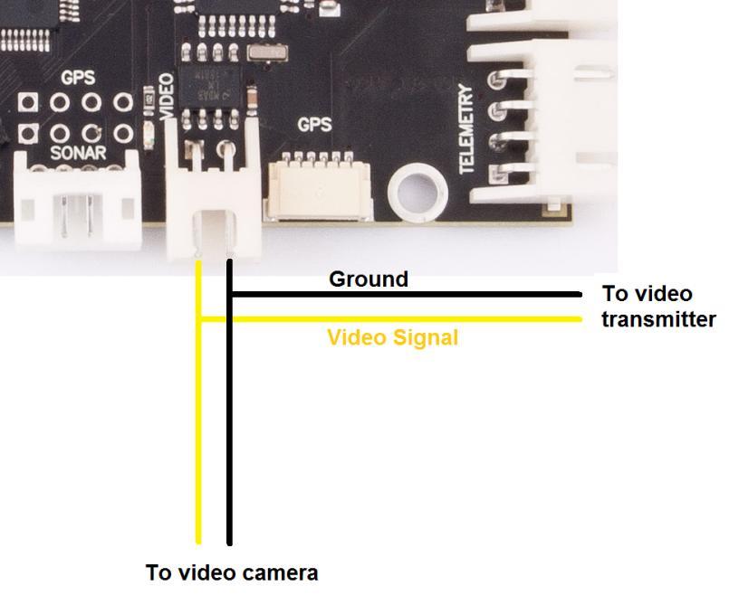
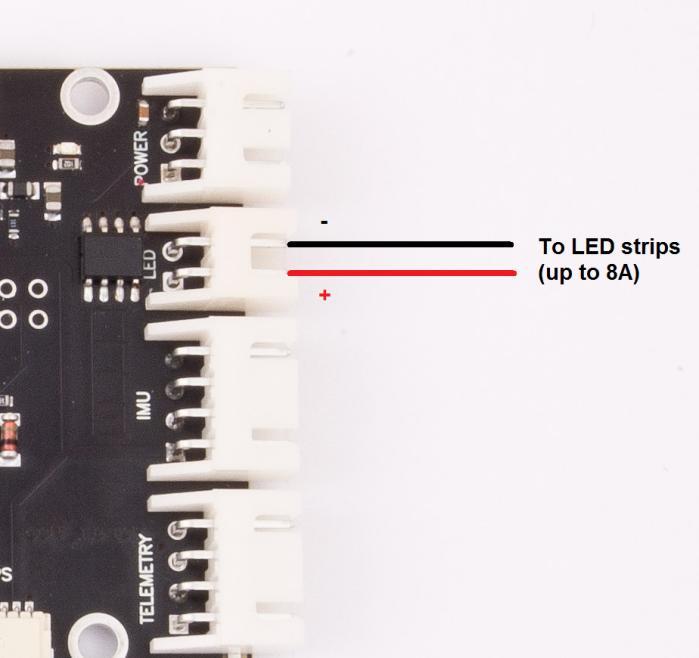
17 Connecting OSD Connecting LEDs 17
User s Guide. SmartAP 2.0 AutoPilot. All rights reserved. 1 SmartAP AutoPilot User s Guide
 1 SmartAP AutoPilot User s Guide SmartAP 2.0 AutoPilot User s Guide All rights reserved 2 SmartAP AutoPilot User s Guide Contents Contents... 2 Introduction... 3 Description... 3 Flight Modes Overview...
INSTRUCTIONS. 3DR Plane CONTENTS. Thank you for purchasing a 3DR Plane!
 DR Plane INSTRUCTIONS Thank you for purchasing a DR Plane! CONTENTS 1 1 Fuselage Right wing Left wing Horizontal stabilizer Vertical stabilizer Carbon fiber bar 1 1 1 7 8 10 11 1 Audio/video (AV) cable
FY-41AP Autopilot & OSD System Installation & Operation Manual
 FY-41AP Autopilot & OSD System Installation & Operation Manual Multi-rotor Version V2.22 And Above Guilin Feiyu Technology Incorporated Company Addr : 3rd Floor,B,Guilin Electric Valley,Innovation Building,
FY-41AP Autopilot & OSD System
 FY-41AP Autopilot & OSD System Installation & Operation Manual (Multi-rotor Version) Guilin Feiyu Electronic Technology Co., Ltd Address: 4 th Floor,YuTaiJie Science Technology Building, Information Industry
FY-DOS Manual For Multi-rotors Control
 FY-DOS Manual For Multi-rotors Control Installation & Operation Multi-rotor firmware above V2.20 Dear Customer: Thank you for choosing DOS as your autopilot system. Please read this manual carefully before
DIY KITS FRAME KIT. Thank you for purchasing a 3DR Y6 DIY Kit!
 DIY KITS Y6 FRAME KIT Thank you for purchasing a 3DR Y6 DIY Kit! These instructions will guide you through assembling and wiring your new autonomous multicopter. CONTENTS Your 3DR Y6 Kit contains: 35 mm
Multi-rotor flight stabilization & Autopilot System Installation & Operation Guide. Guilin Feiyu Electronic Technology Co., Ltd
 Rev: 5 th July 2011 FEIYU TECH FY-91Q DREAMCATCHER Multi-rotor flight stabilization & Autopilot System Installation & Operation Guide Guilin Feiyu Electronic Technology Co., Ltd Rm. B305, Innovation Building,
FY-91Q DREAMCATCHER TECH. Multi-rotor flight stabilization & Autopilot System Installation & Operation Guide
 Rev 6: 7 th July 2011 FEIYU TECH FY-91Q DREAMCATCHER Multi-rotor flight stabilization & Autopilot System Installation & Operation Guide Guilin Feiyu Electronic Technology Co., Ltd Rm. B305, Innovation
Black Knight. Black Knight 210/250 FPV Quadcopter Manual
 Black Knight Black Knight 210/250 FPV Quadcopter Manual Version: Naze V6 V1.1 www.spedix-rc.com WARNING For age 14+ only. Rotating propellers may cause serious injury and damages! Do not install propellers
TEAM AERO-I TEAM AERO-I JOURNAL PAPER DELHI TECHNOLOGICAL UNIVERSITY Journal paper for IARC 2014
 TEAM AERO-I TEAM AERO-I JOURNAL PAPER DELHI TECHNOLOGICAL UNIVERSITY DELHI TECHNOLOGICAL UNIVERSITY Journal paper for IARC 2014 2014 IARC ABSTRACT The paper gives prominence to the technical details of
Skylark OSD V4.0 USER MANUAL
 Skylark OSD V4.0 USER MANUAL A skylark soars above the clouds. SKYLARK OSD V4.0 USER MANUAL New generation of Skylark OSD is developed for the FPV (First Person View) enthusiasts. SKYLARK OSD V4.0 is equipped
FLCS V2.1. AHRS, Autopilot, Gyro Stabilized Gimbals Control, Ground Control Station
 AHRS, Autopilot, Gyro Stabilized Gimbals Control, Ground Control Station The platform provides a high performance basis for electromechanical system control. Originally designed for autonomous aerial vehicle
FY-DOS Manual For Multi-rotors Control
 FY-DOS Manual For Multi-rotors Control Installation & Operation Multi-rotor firmware above V2.10 Dear Customer: Thank you for choosing DOS as your autopilot system. Please read this manual carefully before
DragonLink Advanced Transmitter
 DragonLink Advanced Transmitter A quick introduction - to a new a world of possibilities October 29, 2015 Written by Dennis Frie Contents 1 Disclaimer and notes for early release 3 2 Introduction 4 3 The
EEL 4665/5666 Intelligent Machines Design Laboratory. Messenger. Final Report. Date: 4/22/14 Name: Revant shah
 EEL 4665/5666 Intelligent Machines Design Laboratory Messenger Final Report Date: 4/22/14 Name: Revant shah E-Mail:revantshah2000@ufl.edu Instructors: Dr. A. Antonio Arroyo Dr. Eric M. Schwartz TAs: Andy
EzOSD Manual. Overview & Operating Instructions Preliminary. April ImmersionRC EzOSD Manual 1
 EzOSD Manual Overview & Operating Instructions Preliminary. April 2009 ImmersionRC EzOSD Manual 1 Contents Overview... 3 Features... 3 Installation... 3 1. Installation using an ImmersionRC camera and
FY-DoS for multi-rotors control manual
 FY-DoS for multi-rotors control manual Feiyu Tech Installation & Operation Multi-rotor firmware above V2.10 Dear Customer: Thank you for choosing DoS as your autopilot system. Please read this manual carefully
FOXTECH Nimbus VTOL. User Manual V1.1
 FOXTECH Nimbus VTOL User Manual V1.1 2018.01 Contents Specifications Basic Theory Introduction Setup and Calibration Assembly Control Surface Calibration Compass and Airspeed Calibration Test Flight Autopilot
Study of M.A.R.S. (Multifunctional Aero-drone for Remote Surveillance)
") Study of M.A.R.S. (Multifunctional Aero-drone for Remote Surveillance) Supriya Bhuran 1, Rohit V. Agrawal 2, Kiran D. Bombe 2, Somiran T. Karmakar 2, Ninad V. Bapat 2 1 Assistant Professor, Dept. Instrumentation,
Study of M.A.R.S. (Multifunctional Aero-drone for Remote Surveillance) Supriya Bhuran 1, Rohit V. Agrawal 2, Kiran D. Bombe 2, Somiran T. Karmakar 2, Ninad V. Bapat 2 1 Assistant Professor, Dept. Instrumentation,
Thank you for purchasing this DJI product. Please strictly follow these steps to mount and connect this system on
 NAZA-M LITE User Manual V 1.00 2013.05.28 Revision For Firmware Version V1.00 & Assistant Software Version V1.00 Thank you for purchasing this DJI product. Please strictly follow these steps to mount and
Skylark Trace IV User Manual
 Skylark Trace IV User Manual A skylark soars above the clouds. 一只云雀在云上翱翔 WWW.SkylarkFPV.com SATETY WARNING SKYLARK OSD is for entertainment purpose only, users should bear all the risks involved when using
Autopilot System Installation & Operation Guide. Guilin Feiyu Electronic Technology Co., Ltd
 2011-11-26 FEIYU TECH FY31AP Autopilot System Installation & Operation Guide Guilin Feiyu Electronic Technology Co., Ltd Rm. C407, Innovation Building, Information Industry Park, Chaoyang Road, Qixing
YS-S4 Multi-rotor Autopilot User Manual V1.4
 User Manual V1.4 YS-S4 Multi-rotor Autopilot Zero UAV (Beijing) Intelligence Technology Co. Ltd 1 1. In-Box...3 2. Functions... 4 3. Installation... 5 4. Connections...6 4.1 Assembly... 6 4.2 Real connection
HKPilot Mega 2.7. Flight Controller USB/GYRO/ACC/MAG/BARO
 HKPilot Mega 2.7 Flight Controller USB/GYRO/ACC/MAG/BARO 1 HKPILOT MEGA 2.7 Features: 3.3v issue of bad Gyro heath resolved in the 2.7 Connectors relocated for better wire layout Mux Port added for OSD
X8-M. Operation Manual
 X8-M Operation Manual Thank you for purchasing an X8-M! This manual contains important information about your aerial mapping platform. Please read these instructions before your first flight. 1 Plan 1
Revision For Firmware Version V3.30 or above & Adjusting-parameter software Version V1.40 or above
 T1 User Manual V1.4 2016.07.20 Revision For Firmware Version V3.30 or above & Adjusting-parameter software Version V1.40 or above Please strictly follow these steps to mount and use this product, as well
instruction manual for Open LRS New Generation
 instruction manual for Open LRS New Generation Table of contents 1. Important warnings 2. Hardware Overview 3 2.1 DTF UHF 4 Channel 4 2.2 HobbyKing RX 5 3. Instructions 3.1 Basic functions 6 3.2 Flashing
Acro Naze32 (rev 5) basic guide
 basic guide") Acro Naze32 (rev 5) basic guide by Dlearnt 20 August 2014 1 Introduction I came to this board from a KK (trying a cc3d in between), and wished there was a guide like this to make things a bit easier. This
Acro Naze32 (rev 5) basic guide by Dlearnt 20 August 2014 1 Introduction I came to this board from a KK (trying a cc3d in between), and wished there was a guide like this to make things a bit easier. This
RC Camera Control. User Guide v1.3 (RCCC v1.1) 11/7/2012
 11/7/2012") RC Camera Control User Guide v1.3 (RCCC v1.1) 11/7/2012 kristaps_r@rcgroups INTRODUCTION RC Camera Control board (RCCC) is multifunctional control board designed to for aerial photography or First Person
RC Camera Control User Guide v1.3 (RCCC v1.1) 11/7/2012 kristaps_r@rcgroups INTRODUCTION RC Camera Control board (RCCC) is multifunctional control board designed to for aerial photography or First Person
Manual for Hyperion Receivers 1. Binding Step 1. Power up the receiver in bind mode
 - This is not a Horizon Hobbies DSM2, DSMX product, and is not manufactured or endorsed by Horizon Hobbies LLC. DSM2, and DSMX are registered trademarks of Horizon Hobbies LLC. Manual for Hyperion Receivers
Long Range Wireless OSD 5.8G FPV Transmitter
 Long Range Wireless OSD 5.8G FPV Transmitter Built-in 10 Axis AHRS + MAVLINK + 600mW Support all flight controller and GPS 1 / 14 User's Guide Catalogue Product Instruction 3 Features 3 Specifications.4
Using the 9XR Pro for More than Eight Channels
 Appendix B Using the 9XR Pro for More than Eight Channels Introduction In stock form, with a module such as the FrSky DJT or OrangeRx DSMX/DSM2 installed, the Turnigy 9XR Pro transmitter can control a
AUTOPILOT QUICK START GUIDE
 AUTOPILOT QUICK START GUIDE The view of PIXHAWK2.1 Ports: GPS1/GPS2 TELEM1/TELEM2 I2C 2 USB Analog to digital converter 3.3 V CAN1/CAN2 Spektrum DSM receiver POWER1 POWER2 S.BUS out for servo SERIAL 5
A3 Pro INSTRUCTION MANUAL. Oct 25, 2017 Revision IMPORTANT NOTES
 A3 Pro INSTRUCTION MANUAL Oct 25, 2017 Revision IMPORTANT NOTES 1. Radio controlled (R/C) models are not toys! The propellers rotate at high speed and pose potential risk. They may cause severe injury
Introduction. Overview. Outputs Normal model 4 Delta wing (Elevon) & Flying wing & V-tail 4. Rx states
 & Flying wing & V-tail 4. Rx states") Introduction Thank you for purchasing FrSky S6R/S8R (SxR instead in this manual) multi-function telemetry receiver. Equipped with build-in 3-axis gyroscope and accelerometer, SxR supports various functions.
Introduction Thank you for purchasing FrSky S6R/S8R (SxR instead in this manual) multi-function telemetry receiver. Equipped with build-in 3-axis gyroscope and accelerometer, SxR supports various functions.
Advanced User Manual
 Features Advanced User Manual Applications BL-3G Ultra stable 3-Axis Gyro Small size, weight and power USB / PC connection for set up and upgrade MEMS rate sensor - Ultra stable over temperature and time
BREEZE OSD pro V1.1 manual
 BREEZE OSD pro V1.1 manual Thanks for purchasing Cyclops OSD products. Connection diagram Important: select Jumper instructions: 1, 2 short circuit for using power batteries(which must be 12V, or 3S Lipo
Application Note. Communication between arduino and IMU Software capturing the data
 Application Note Communication between arduino and IMU Software capturing the data ECE 480 Team 8 Chenli Yuan Presentation Prep Date: April 8, 2013 Executive Summary In summary, this application note is
Introducing the Quadrotor Flying Robot
 Introducing the Quadrotor Flying Robot Roy Brewer Organizer Philadelphia Robotics Meetup Group August 13, 2009 What is a Quadrotor? A vehicle having 4 rotors (propellers) at each end of a square cross
Project Name: Tail-Gator
 EEL 4924 Electrical Engineering Design (Senior Design) Final Report 22 April 2013 Project Name: Tail-Gator Team Name: Eye in the Sky Team Members: Name: Anthony Incardona Name: Fredrik Womack Page 2/14
Product Introduction:
 Product Introduction: ARKBIRD-433UHF is a 10-channel module designed for long-distance flight: 1. The advanced code division frequency hopping system (FHSS) produces the only way of frequency hopping sequence
Classical Control Based Autopilot Design Using PC/104
 Classical Control Based Autopilot Design Using PC/104 Mohammed A. Elsadig, Alneelain University, Dr. Mohammed A. Hussien, Alneelain University. Abstract Many recent papers have been written in unmanned
1. Line Follower Placing the Line Follower Electrical Wiring of Line Follower Source Code Example and Testing...
 CONTENTS 1. Line Follower... 2 1.1 Placing the Line Follower... 2 1.2 Electrical Wiring of Line Follower... 3 1.3 Source Code Example and Testing... 4 2. CMPS11 Compass... 5 2.1 Placing the Compass on
Mini-Expansion Unit (MEU) User Guide V1.2
 User Guide V1.2") Mini-Expansion Unit (MEU) User Guide V1.2 Disclaimer Although every care is taken with the design of this product, JT Innovations Ltd. can in no way be held responsible for any consequential damage resulting
Mini-Expansion Unit (MEU) User Guide V1.2 Disclaimer Although every care is taken with the design of this product, JT Innovations Ltd. can in no way be held responsible for any consequential damage resulting
OughtToPilot. Project Report of Submission PC128 to 2008 Propeller Design Contest. Jason Edelberg
 OughtToPilot Project Report of Submission PC128 to 2008 Propeller Design Contest Jason Edelberg Table of Contents Project Number.. 3 Project Description.. 4 Schematic 5 Source Code. Attached Separately
Attack on the drones. Vectors of attack on small unmanned aerial vehicles Oleg Petrovsky / VB2015 Prague
 Attack on the drones Vectors of attack on small unmanned aerial vehicles Oleg Petrovsky / VB2015 Prague Google trends Google trends This is my drone. There are many like it, but this one is mine. Majority
A3-AG/N3-AG. Agriculture Kit. User Manual V
 A3-AG/N3-AG Agriculture Kit User Manual V2.0 2017.08 Contents A3-AG Introduction 3 N3-AG Introduction 6 Agriculture Management Unit (AMU) Introduction 9 Installation 10 Overview 10 Start the Installation
Introduction to Multicopter Design and Control
 Introduction to Multicopter Design and Control Lesson 14 Health Evaluation and Failsafe Quan Quan, Associate Professor qq_buaa@buaa.edu.cn BUAA Reliable Flight Control Group, http://rfly.buaa.edu.cn/ Beihang
NAZA-M Quick Start Guide V 1.0
 NAZA-M Quick Start Guide V 1.0 Thank you for purchasing this DJI product. Please regularly visit the NAZA-M web page at www.dji-innovations.com. This page is updated regularly. Any technical updates and
All other trademarks are trademarks or registered trademarks of their respective holders.
 Rev 1.1 TECHNICAL DESCRIPTION Fastrax IT500 GPS Receiver This document describes the electrical connectivity and main functionality of the IT500 hardware. August 31, 2009 Fastrax Ltd. Page 2 of 31 TRADEMARKS
X4V2 Flight Controller Manual V1.1
 X4V2 Flight Controller Manual V1.1 Zero UAV (Beijing) Intelligence Technology Co., Ltd. Table of Contents 1 Warning and Disclaimer... 1 2 Terms and Abbreviations... 3 3 Functions... 4 4 In the Box... 5
A2 Flight Control System
 A2 Flight Control System User Manual V1.26 April, 2017 Revision Thank you for purchasing DJI products. Please strictly follow these steps to mount and connect this system on your aircraft, install the
Arkbird Hummingbird BNF Version Airplane User Manual Caution
 Arkbird Hummingbird BNF Version Airplane User Manual Caution 1) Please abide by relevant laws: No flying in populated area, no flying in airport clearance area (10km away from both sides of the runway,
August/5/2010 FY-20A FLIGHT STABILIZATION SYSTEM TECH INSTALLATION & OPERATION MANUAL
 August/5/2010 FEIYU TECH FY-20A FLIGHT STABILIZATION SYSTEM INSTALLATION & OPERATION MANUAL Dear Pilot, Thank you for purchasing the FY-20A stabilizer from FeiYu Tech. In order to achieve full potential
The Next Generation Design of Autonomous MAV Flight Control System SmartAP
 The Next Generation Design of Autonomous MAV Flight Control System SmartAP Kirill Shilov Department of Aeromechanics and Flight Engineering Moscow Institute of Physics and Technology 16 Gagarina st, Zhukovsky,
computer radio control system COMPLEX RADIO CONTROL SYSTEM Receivers REX
 COMPLEX RADIO CONTROL SYSTEM User Manual Receivers REX FW 1.05 1. Introduction... 04 2. Technical data... 05 2.1 Properties... 06 2.2 Important Notices... 06 3. Installation... 08 3.1 Installation in the
Castle Multi-Rotor ESC Series User Guide
 Castle Multi-Rotor ESC Series User Guide This user guide is applicable to all models of Castle Multi-Rotor ESC. Important Warnings Castle Creations is not responsible for your use of this product or for
Veyron Servo Driver (24 Channel) (SKU:DRI0029)
 (SKU:DRI0029)") Veyron Servo Driver (24 Channel) (SKU:DRI0029) From Robot Wiki Contents 1 Introduction 2 Specifications 3 Pin Definitions 4 Install Driver o 4.1 Windows OS Driver 5 Relationship between Steering Angle
Veyron Servo Driver (24 Channel) (SKU:DRI0029) From Robot Wiki Contents 1 Introduction 2 Specifications 3 Pin Definitions 4 Install Driver o 4.1 Windows OS Driver 5 Relationship between Steering Angle
Table of Contents 1 Introduction Overview Package Contents Specifications Software Updates Changelog
 DRAFT ONLY Table of Contents 1 Introduction 4 1.1 Overview 4 1.2 Package Contents 5 1.3 Specifications 5 1.4 Software Updates 6 1.4.1 Changelog 6 1.4.2 Known Issues and Limitations 6 1.5 Product Support
Manual Electric Air-Module 2-14 S with Vario Graupner HoTT 2.4
 Manual 33620 Electric Air-Module 2-14 S with Vario Graupner HoTT 2.4 CONTENTS: 1. Description... 01 2. Mounting the module in the plane... 01 3. Quick Guide... 02 3.1. Connection of sensors... 03 4. Starting
Caution Notes. Features. Specifications. Installation. A3-L 3-axis Gyro User Manual V1.0
 Caution Notes Thank you for choosing our products. If any difficulties are encountered while setting up or operating it, please consult this manual first. For further help, please don t hesitate to contact
IMU: Get started with Arduino and the MPU 6050 Sensor!
 1 of 5 16-3-2017 15:17 IMU Interfacing Tutorial: Get started with Arduino and the MPU 6050 Sensor! By Arvind Sanjeev, Founder of DIY Hacking Arduino MPU 6050 Setup In this post, I will be reviewing a few
Doc Version 1.2 GPS RECEIVER ENGINE BOARD
 Doc Version 1.2 EM-411 GPS RECEIVER ENGINE BOARD G LO B AL S AT T E CHNOLOGY CO RPORAT I O N GPS Engine Board Specifications REVISIONS V1.0 10-01-2006 Convert test to USG format V1.1 10-23-2006 Update
SETUP GUIDE REVISION C SETUP GUIDE
 SETUP GUIDE REVISION C 03.18.2016 SETUP GUIDE 2 WWW.FREEFLYSYSTEMS.COM TABLE OF CONTENTS 04 Disclaimer and Warning 07 Introduction 13 Unboxing ALTA 16 Weight Limitations 18 Disarm Safety Switch 19 Control
Atlas-450 FPV Brushless FPV
 Atlas-450 FPV Brushless FPV Atlas-450 is a kind of micro brushless FPV delta-wing airplane base on the design idea of reliability, safety and concise, her flight time is as long as 20 minutes! Park flying
CONDOR C1722 GPS RECEIVER MODULE technical notes
 CONDOR C1722 GPS RECEIVER MODULE TECHNICAL HIGHLIGHTS Receiver: GPS L1 frequency (1575.42 MHz), C/A code, 22-channel continuous tracking NMEA output and input: serial port, USB port On-board low noise
Demon Pumpkin APPROXIMATE TIME (EXCLUDING PREPARATION WORK): 1 HOUR PREREQUISITES: PART LIST:
: 1 HOUR PREREQUISITES: PART LIST:") Demon Pumpkin This is a lab guide for creating your own simple animatronic pumpkin. This project encourages students and makers to innovate upon the base design to add their own personal touches. APPROXIMATE
Demon Pumpkin This is a lab guide for creating your own simple animatronic pumpkin. This project encourages students and makers to innovate upon the base design to add their own personal touches. APPROXIMATE
A2 Flight Control System
 A2 Flight Control System User Manual V1.18 June 24th, 2014 Revision For Firmware 2.2 & Assistant Software V1.3 & DJI Assistant App V1.1.14 Thank you for purchasing DJI products. Please strictly follow
Guilin Feiyu Electronic Technology Co., Ltd. Guilin FeiYu Electronic Technology Co.
 Hornet-OSD Manual Feiyu Tech Guilin FeiYu Electronic Technology Co., Ltd Addr:Room C407, Innovation Building, Information Industry Park, ChaoYang Road, QiXing District, Guilin China Web:http://www.feiyudz.cn
TBS CROSSFIRE R/C System Revision Adaptive Long Range Remote Control System
 TBS CROSSFIRE R/C System Revision 2015-12-05 Adaptive Long Range Remote Control System The TBS CROSSFIRE system is a R/C link system made for FPV enthusiasts. It features unheard of range without sacrificing
Mapping with the Phantom 4 Advanced & Pix4Dcapture Jerry Davis, Institute for Geographic Information Science, San Francisco State University
 Mapping with the Phantom 4 Advanced & Pix4Dcapture Jerry Davis, Institute for Geographic Information Science, San Francisco State University The DJI Phantom 4 is a popular, easy to fly UAS that integrates
MD04-24Volt 20Amp H Bridge Motor Drive
 MD04-24Volt 20Amp H Bridge Motor Drive Overview The MD04 is a medium power motor driver, designed to supply power beyond that of any of the low power single chip H-Bridges that exist. Main features are
CONDOR C1919 GPS RECEIVER MODULE technical notes GENERAL OVERVIEW
 CONDOR C1919 GPS RECEIVER MODULE TECHNICAL HIGHLIGHTS Receiver: GPS L1 frequency (17. MHz), C/A code, -channel continuous tracking NMEA output and input: serial port On-board low noise amplifier GENERAL
User Guide. Advanced Ground Control Station Unit & Antenna Tracker RVGS. RangeVideo RVGS Control Station Manual 1
 Advanced Ground Control Station Unit & Antenna Tracker RVGS RangeVideo RVGS Control Station Manual 1 Your Guide To the Ground Station Control and Antenna Tracker Unit Table of Contents 1. Introducing RVGS
DROTAG - Sony Alpha Series Image Tagging
 AIRBORNE PROJECTS Airborne Projects specializes in building drone solutions with emphasis on telemetry gathering and integration with avionics and automatic flight systems. DROTAG - Sony Alpha Series Image
ENHANCEMENTS IN UAV FLIGHT CONTROL AND SENSOR ORIENTATION
 Heinz Jürgen Przybilla Manfred Bäumker, Alexander Zurhorst ENHANCEMENTS IN UAV FLIGHT CONTROL AND SENSOR ORIENTATION Content Introduction Precise Positioning GNSS sensors and software Inertial and augmentation
Pitlab & Zbig FPV System Version 2.60a. Pitlab&Zbig OSD. New functions and changes in v2.60. New functions and changes since version 2.
 Pitlab & Zbig FPV System Version 2.60a since version 2.50a Pitlab&Zbig OSD in v2.60a Added support for new Pitlab airspeed sensor. Sensor is connected to yellow OSD socket and is configured in similar
GLOBALSAT GPS Engine Board
 GLOBALSAT GPS Engine Board Hardware Datasheet Product No : MT-332(SMA) Version 1.0 GlobalSat WorldCom Corporation 16F., No. 186, Jian-Yi Road, Chung-Ho City, Taipei Hsien 235, Taiwan Tel: 886-2-8226-3799
DragonLink V3 Advanced Complete System. DragonLink OSD DRAFT ONLY. User Guide v0.3 Sep Applicable versions:
 DragonLink V3 Advanced Complete System DragonLink OSD DRAFT ONLY User Guide v0.3 Sep 2018 Applicable versions: UI: 3.0.2.0, RX/TX: 18 April 2018, OSD: 272 1 P age Table of Contents 1 Introduction 5 1.1
GLOBALSAT GPS Engine Board
 GLOBALSAT GPS Engine Board Hardware Data Sheet Product No : MT-5531 Version 0.1 Globalsat Technology Corporation 16F., No. 186, Jian-Yi Road, Chung-Ho City, Taipei Hsien 235, Taiwan Tel: 886-2-8226-3799
Storm Racing Drone SRD370. with DJI Naza Lite or DJI Naza V2 USER MANUAL. HeliPal.com. All Rights Reserved
 Storm Racing Drone SRD370 with DJI Naza Lite or DJI Naza V2 USER MANUAL V6! 1 DISCLAIMER Please read this disclaimer carefully before using this product. This product is a hobby with motors but not a toy
MicroVector Multirotor/Fixed Wing Flight Controller + OSD User Guide
 MicroVector Multirotor/Fixed Wing Flight Controller + OSD User Guide August, 2017 Version 1.4 Software Version 12.60+ 1 Table of Contents Contents 1 Safety... 8 1.1... Read the Manual!...8 1.2... Special
New functions and changes summary
 New functions and changes summary A comparison of PitLab & Zbig FPV System versions 2.50 and 2.40 Table of Contents New features...2 OSD and autopilot...2 Navigation modes...2 Routes...2 Takeoff...2 Automatic
QLG1 GPS Receiver kit
 QLG1 GPS Receiver kit 1. Introduction Thank you for purchasing the QRP Labs QLG1 GPS Receiver kit. This kit will provide a highly sensitive, highly accurate GPS receiver module, using the popular MediaTek
A3 SUPER 3 INSTRUCTION MANUAL. For Firmware Version 1.0, Data Version 1.0 Oct 25, 2017 Revision.
 A3 SUPER 3 INSTRUCTION MANUAL For Firmware Version 1.0, Data Version 1.0 Oct 25, 2017 Revision support@hobbyeagle.com 1 CONTENTS IMPORTANT NOTES.....3 1. Introduction......4 2. Setup Procedure Overview...5
Hopper Spacecraft Simulator. Billy Hau and Brian Wisniewski
 Hopper Spacecraft Simulator Billy Hau and Brian Wisniewski Agenda Introduction Flight Dynamics Hardware Design Avionics Control System Future Works Introduction Mission Overview Collaboration with Penn
Height Limited Switch
 Height Limited Switch Manual version: 1.0 Content Introduction...3 How it works...3 Key features...3 Hardware...4 Motor cut-off settings...4 Specification...4 Using the RC HLS #1 module...5 Powering the
DEVELOPMENT OF AN AUTONOMOUS SMALL SCALE ELECTRIC CAR
 Jurnal Mekanikal June 2015, Vol 38, 81-91 DEVELOPMENT OF AN AUTONOMOUS SMALL SCALE ELECTRIC CAR Amzar Omairi and Saiful Anuar Abu Bakar* Department of Aeronautics, Automotive and Ocean Engineering Faculty
Xtreme Power Systems
 Xtreme Power Systems XtremeLink NANO RECEIVER Installation And Usage Manual XtremeLink is a registered trademark of Xtreme Power Systems, LLC. Firmware v 1.9 Manual v 1.9 Revision Date: November 11 th,
ESC32 2r1 user manual - version 0.0
 Autoquad ESC32 Features: - STM32F103 72MHz ARM 32-bit Cortex(TM) M3 MCU - All N-FET design with gate drivers - 2S through 5S battery voltage - Option to power logic side via UART or PWM IN at +5V - CAN
32-channel GPS Engine Board SmartAntenna
 32-channel GPS Engine Board SmartAntenna with MTK Chipset The document is the exclusive property of and should not be distributed, reproduced, or any other format without prior permission of Specifications
RY836AI. High Performance GPS & Glonass / GPS & BeiDou Parallel mode antenna module with Compass, Gyroscope, Accelerometer, Pressure Sensor.
 27-OCT-2017 56312E31 High Performance GPS & Glonass / GPS & BeiDou Parallel mode antenna module with Compass, Gyroscope, Accelerometer, Pressure Sensor Datasheet PRODUCT DESCRIPTION The REYAX GNSS receiver
BRB900 GPS Telemetry System August 2013 Version 0.06
 BRB900 GPS Telemetry System August 2013 Version 0.06 As of January 2013, a new model of the BRB900 has been introduced. The key differences are listed below. 1. U-blox GPS Chipset: The Trimble Lassen IQ
Arkbird OSD 2.0 Includes:
 ARKBIRD is a high-accuracy autopilot designed for fixed-wing. It can superimpose OSD (On Screen Display) data on videos and at the same time control the balance, the return and many other maneuvers of
SV613 USB Interface Wireless Module SV613
 USB Interface Wireless Module SV613 1. Description SV613 is highly-integrated RF module, which adopts high performance Si4432 from Silicon Labs. It comes with USB Interface. SV613 has high sensitivity
UP30 UAV Autopilot System Manual Version 5.7
 UP30 UAV Autopilot System Manual Version 5.7-0 - CONTENTS Warning, warranty and upgrade.....3 Warning....... 3 Warranty...... 3 Upgrade....... 3 Contact..... 4 Introduction to UP30 Autopilot System....
Downwelling Light Sensor 2 (DLS 2) Integration Guide
 Integration Guide") Downwelling Light Sensor 2 (DLS 2) Integration Guide Revision 01, November 2018 Seattle, WA 2018 MicaSense, Inc. Page 1 of 17 Table of Contents Overview and Scope 3 Measurements and Attachment Points 4
Downwelling Light Sensor 2 (DLS 2) Integration Guide Revision 01, November 2018 Seattle, WA 2018 MicaSense, Inc. Page 1 of 17 Table of Contents Overview and Scope 3 Measurements and Attachment Points 4
SA-320 Installation Guide SA-320. Installation Guide. Date: Mar, 2011 Version: 2.5. All Rights Reserved
 SA-320 Installation Guide Date: Mar, 2011 Version: 2.5 All Rights Reserved Page 1 TABLE OF CONTENTS 1. Product Overview......3 1.1 Main Features...3 1.2 Applications.....3 1.3 Package Content.....3 2.
era, eric, era-lora, eric-lora & eric-sigfox Evaluation Board with GNSS
 This board can be used for the evaluation and range testing of the following LPRS RF Modules: era400, era900, eric4, eric9, era-lora, eric-lora and eric-sigfox. The board is provided with a u-blox GNSS
High Current DC Motor Driver Manual
 High Current DC Motor Driver Manual 1.0 INTRODUCTION AND OVERVIEW This driver is one of the latest smart series motor drivers designed to drive medium to high power brushed DC motor with current capacity