for CCTA Member Companies Mario Sebastiani Tony Holmes
|
|
|
- Timothy Bell
- 6 years ago
- Views:
Transcription
1 Maintenance a Activities t on the Digital HFC Network for CCTA Member Companies August 16, 17, 18, 2011 San Juan, Puerto Rico Mario Sebastiani Tony Holmes
2 Technical Session Overview Challenges faced by the technician The importance of the parameters which affects QoS Implementing a well planned maintenance program Understanding the Triple Play Wh t t l il bl t i t h i i What tools are available to increase technician efficiency
3 Session One Downstream/Upstream Testing Return Path Monitoring Certifying the Return Path Work Management Logging Generating Reports
4 Downstream/Upstream Testing
5 Aligning the Forward Path
6 Forward Sweep
7 Frequency Response Definition iti System s ability to properly transmit signals from head-end to subscriber throughout the designed frequency range Sweep tests t verify performance to design specifications Expected results: n/10 + x = max flatness variation Where n = number of amplifiers in cascade Where x = best case flatness figure (supplied by manufacturer)
8 Why Sweep? SpeedSweep makes it easier for technicians to find: Reflections Water Migration Damaged cable Suck-Outs Cable Roll-Off Loose or cracked connectors Craftsmanship errors
9 Why Sweep? Allowsareferencetobestored stored Sweep makes it possible to divide the HFC plant into network sections and test its performance against individual specifications Can measure in unused frequencies This is most important during construction and system overbuilding
10

11 Insertion Diagram Node Forwa ard Comb iner Node Head-end 860 DSPi

12 Sweep Forward Path Head-end Hub Sweep from node out
13 Start at node Sweep Forward Path Verify unity gain Align RF portion of node at test point Store a reference at the node Balance trunk first Then work out into the feeder


14 Sweep on 860 DSPi Reference name can have up to 8 alphanumeric characters channels sweep points Tilt Compensation 860 DSPi with no reference 860 DSPi with reference
15 860 DSPi Sweep Display Reference Scale factor Markers Averaging Tilt Compensation Max variation Marker frequencies Marker relative levels
16 Automatic distance to fault Standing Waves
17 Standing Waves
18 Suck-Out
19 Suck-Out
20 Roll-Off
21 Return Path Testing


22 Headend d Diagram Forward Combiner Opt Trans Forward Telemetry CMTS Headend Device Return Input TP Opt Recv Node TP 860 DSPi
23 Return Sweep Balancing of the System Sweep Signals transmitted by field unit are recovered and analyzed at headend Gain, Tilt and Frequency Response of sweep carriers are returned to the field unit via a downstream telemetry t carrier (50MH MHz to 1GH GHz) Start at node Store Reference trace Proceed to amplifier
24 Sweep Return Path Hub Headend Start at node and sweep out
25 Return Sweep Sweep Screen Plots received level in the Headend for each sweep carrier Scale 1, 2, 5, & 10 db per Division Ideal Trace is a flat line Gain Information Difference between Headend nominal and sweep carrier level Tilt Information Difference between low and high pilot carrier levels Displays impairments i to frequency response Damaged cable, actives, or passives Low or High end roll off


26 Return Sweep Gain Tilt TP The return sweep displays the Gain &Tilt at the top of the screen
27 Return Sweep Displays both sweep & ingress screen while sweeping The Ingress can be turned ON/OFF Via the FN Key
28 Sweep & Ingress Move marker location until locate the frequency of the ingress Return Sweep
29 Return Sweep Possible causes of High Noise Levels Excessive gain System integrity Remedies: Balance trunk first then work out into the feeder to adjust Pads & EQ s Keep all fittings tight, fix all rodent chews & tree rubs, plus watch out for backhoes
30 Return Path Certification and Monitoring
31 Certifying i Return Path There have been as many methods and specifications Examples include a one-hour max hold ten minutes max hold The results are considered to demonstrate that over this period the network would either pass or fail based on the amount of junk viewed
32 Certifying i Return Path (cont.) Voip is not a 1 hour service 24 hour 7 days a week This maximum measurement is also not indicative of the true performance of the network The certification process should be at least a twenty- four hour certification Should be an on-going figure of merit.
33 Troubleshooting Summary Verify at the node Determine which leg(s) are contributing to the problem Identify the span Using amplifier test points Get ahead of the problem Isolate to the tap Using a return path test probe isolate the problem Pinpoint the origin To a tap (subscriber premise) Damaged Cable
34 Node Certification Report Automates node certification testing Specify Locations and time span Returns Pass/Fail results based on ingress levels vs. user specified limits

35 Node Certification Report Summary Report Includes Header information Summary of test results Pass/Fail results by node
36 Historical Analysis Specifically designed for convenient and efficient historical analysis Archives up to a year of data Displays both historical and live spectral views Calculates the average probability that a node will exceed its thresholds over time
37 Historical i Analysis Tools Recall spectral information over selected time periods View frequency availability of the return path for new service launches Evaluate the impact of changes in modulation schemes on system services Verify existing services are meeting performance standards Generate figure of merit calculations for return performance


38 Spectral History Retrieve Spectral History Both spectral and time based views Evaluate the severity and duration of ingress related events View the waterfall graph
39 ADIA Node Service Report

40 Work Management Logging
41 Field Measurement Data Mgmt. Helps ensure that proper testing is done Leads to higher service quality Cuts down the number of truck rolls Provides data for effective management Reports Queries Saves $$$


42 System Diagram 860 DSPi - Work order retrieval - Test macros/temp storage - File transmission Billing/WFM System - Data file generation WorkBench/TDM Component - TDM user interface - Data display and analysis - Queries, Reports Microsoft IE Browser - Manager/Supervisor access to reports TDM Server - Data communication - Measurement database

43 System Integration WFX Database WFX Workstation TDM Server TDM Administrator
 Queues-up 860 DSPi")

44 Administrator Interaction Administrator (manager/supervisor) Queues-up 860 DSPi configuration changes Channel plans Test macros Firmware Packages Runs reports and queries data as desired


45 Morning Technician Interaction Work order data is replenished daily with data through the use of an automated script may be replenished at any time or frequency. Technician connects to TDM with 860 Gets configuration updates from queue Downloads oadswork odes orders for the eday,o or Creates work orders directly on the meter
46 Daily routine Technician i Interaction ti At job site, technician performs tests with macros Saves results to work order task ID (provided by TDM) Technician accesses next job, which was downloaded from TDM this morning Addresses for all queued jobs are viewable in 860 DSPi task folder Evening Technician uploads all completed data logs to TDM
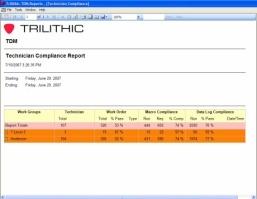
47 Reports Macro summary At-tap node history Calibration check House history Meter inventory Set-top compliance Technician i compliance All reports are storable, and can be ed with expansion/contraction features intact
48 WorkBench Queries Queries enable a user to search for specific data They can be customized to find particular information They can be saved and repeated on demand This is a very flexible, powerful tool


49 Select a saved query or run custom query WorkBench Queries
50 End do of Session Sesso One Questions?
51 Session Two Troubleshooting the QAM Carrier Ingress Troubleshooting Using Leakage Detection ti HSD Troubleshooting VoIP Services The Challenges and Diagnostic Tips Using the Tools and Test Equipment Properly
52 QAM Measurements
53 QAM Measurements Constellation Display MER BER True BER or Estimated
54 Reading Constellation ti The boundary is called the "Decision Threshold If a signal disturbance pushes a symbol across the Threshold it is incorrectly interpreted as belonging in the neighboring box, and becomes a "bit error Symbols that are not disturbed y enough to be pushed across Thresholds are always interpreted correctly Diagrams A constellation diagram is a good troubleshooting aid and can give clues concerning the source and nature of a disturbance
55 Constellation The constellation display shows both I and Q Helps determine modulation problems: Amplitude Imbalance Quadrature Error Phase Error MER
56 Constellation Deviation from the ideal location Good MER Poor MER
57 BER Bit Error Rate is the number of bits in error divided by the total number of bits in the data transmission Pre BER System Margin


58 BER Digital signals work well until very close to the point of failure Measurement of digital carriers critical to determine the system margin Signal level MER BER The BER Mode helps to find problems
59 Forward Error Correction FEC Corrects errors to a point Pre FEC BER (Before Correction) Post FEC BER (After Correction)
60 Digital Troubleshooting Tips Verify that the problem is happening before you troubleshoot Check RF levels MER BER Constellation ti Signal Leakage
61 Digital Troubleshooting Tips cont. The return spectrum for excessive noise What channels are being effective Adaptive Equalizer for reflections Connectors Wiringi What time the problem occurs Diagnostic screens on the set top The noise floor under QAM
62 Error Vector Spectrum To view the noise floor under QAM the To view the noise floor under QAM the carrier needs to be removed
63 Threshold and Margin Signal Quality versus Picture Quality No Picture Perfect Picture Quality Digital Analog Worsening Signal Quality
64 MER TARGET - THE CLIFF EFFECT What is The Cliff Effect?
65 Operating margin Risk Crash Zone Zone Zone
66 Ingress & Egress Ingress RF or electrical energy that enters the coaxial environment Egress RF signal leaking out of the coaxial environment


67 Leakage Detection Benefits Eliminates Ingress Improves System Performance Reduces Repeat Service Calls Locate Physical Problems within y the network
68 Polarization Angle Dipole Monopole
69 Leakage Antennas-Whip
70 Leakage Antennas-Dipole
71 HSD Troubleshooting Tips


72 High Speed Data Downstream is streaming data Constant signal Upstream data signals are bursty
73 Enter Host Name or Host IP Packet Delay (how often packets are transmitted Packet Size (size of packets transmitted Sent and Received Packets Lost Packets LPR (Loss Packet Rate) LPR(%) (Percentage of Loss Packets) Network Ping


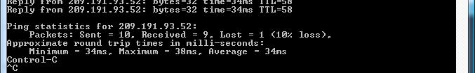
74 Ping from the PC
75 Trace Route Sometimes it s helpful l to run a trace Route from the subscriber s PC This will show the routing point where the transmission stops Some devices can be configured not to respond to ping, as a security measure firewalls for instance


76 Trace Route from the PC


77 Traffic Mode Traffic mode can be used to see the ingress that is present underneath an upstream cable modem carrier, VoIP carrier, or any bursty signal Troubleshooting made easy Divide & Conquer Source typically a home
78 Throughput Test Throughput rates up to 40Mbps Select test at fixed throughput rates, such as 5 Mbps, 10 Mbps, 15 Mbps, 30 Mbps, and 40 Mbps to test various tiered services Test at both the desired speed and one speed higher to prove that t the cable modem is provisioned correctly
79 QAM Source Upstream QAM source verifies the transmission capability of the network for higher order QAM signals QPSK 16 QAM 64 QAM Adjustable Symbol Rate Level Frequency
80 VoIP Troubleshooting
81 How Testing Helps Must be quick to identify, isolate, and solve problems know system health Recruiting customers is expensive, and long-term retention is critical to ROI Loss of voice customer may also mean loss of the rest of the triple-play play revenue
82 VoIP Tests, Pre-Activation
83 Pre-Infrastructure VoIP Testing Prepares system for VoIP service offering by ypre-testing RTP (Real-time Transport Protocol) tests for packet loss, jitter, and delay, with MOS Inexpensive solution, with low-cost headend based server
84 RTP Test Communication established Server and analyzer synchronize test parameters and clocks Communication occurs using RTP over UDP (User Datagram Protocol) at pre-negotiated port Results are calculated and compared to limits p Pass/Fail results

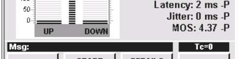
85 Sample Results


86 Sample Results Drill Down Downstream Upstream
87 Mean Opinion Score (MOS) Subjective voice quality score based on the perception of a random group of people listening to speech over a communication system. Group of males and females rate the quality of test sentences read Each person rates from 1 to 5 MOS is average: 1 (worst), 5 (best)
88 Mean Opinion Score (MOS) Rating Definition Description 5 Excellent A perfect speech signal recorded in a quiet booth 4 Good 3 Fi Fair Intelligent and natural like long distance telephone quality Communication quality, but requires some hearing effort 2 Poor Low quality and hard to understand the speech 1 Bad Unclear speech, breakdown
89 Latency (Delay) Causes Echo and Talker Overlap When delay is > 50 msec, echo becomes a problem; echo cancellation is required Talker overlap is significant when one-way delay is > 250 msec
90 Latency (Delay) Can seriously impair i communication Usually a by-product of switching and routing Must be less than 300 msec. round trip
91 Jitter Packets arrive at destination out of timing or sequence Jitter buffer is used to enable re-ordering of packets Increasing size of jitter buffer threatens delay Should be less than twice packetization ation rate Jitter buffer overflow causes packet loss
92 Packet Loss Can be caused by network congestion, jitter buffer overflow, or ingress Random packet loss is less noticeable than bursty packet loss Target <1%, which is less noticeable when loss is random; >4% renders service unusable
93 Task for Headend, Maintenance and Service techs
94 Verifies that the home network will support extended service (HSD, VoIP, VOD, Digital, etc) To detect faults at the premise Why clean it up? The Issues Home wiring architectures Component Requirements Testing & Troubleshooting Recommendations Suggestions for a more available service
95 What checks should we make to ensure a good install
96 Ingress Concerns
97 Ingress on Analog and Digital Lines in picture Channels High speed data problems Interference with two-way radio services using the same frequencies Macro Blocking Freeze Frame Loss of Picture and Sound
98 Alternative Maintenance Techniques High Pass Filters Attenuate Return Path Noise and Ingress coming from the subscriber premise Isolate entertain services from data services Return Path Attenuators Increase the tap loss in the return path only Equalize the loss for subscriber devices and increase isolation between subscriber premise and cable system Drop Testing Testing the integrity of the subscriber wiring
99 Autotest Macros
100 Auto Test Functions Automated Testing of Level (Single or Scan) Hum VoIP Ping QAM Reverse Levels, Ingress Selectable Timing, Channel Plan, Label Test to Limits Results Labeled, Displayed and Stored
101 Remote Signal Monitoring & Analysis
102 Scheduled Reporting Challenge Common task report test signal analysis results all signals on regular schedule Techs required to visit remote locations to verify and report signal quality Time consuming and expensive process, begging for automation ti
103 Eliminate Unnecessary Travel Trips to remote sites no longer required to perform a wide variety of signal quality tests Automate measurements Access for live measurements using Access for live measurements using browser
104 Applications Monitor forward signal quality User definable limits Management application software Manages traps from alarm notification Designated technician/engineer/manager Check current status Similar to 860 DSPi browser access/control
105 Alarm Analysis Display current alarm status Based on traps received Provide easy access to remote devices Activate notification of specified user


106 Interrogator Channel Events Displays channel alarms received from devices. Click once on a channel event to see the Channel Event details. Double-click on a channel event to bring up a live view mode to monitor current channel measurements.
107 Channel Scan (Live Mode)
108 Spectrum Analyzer (Live Mode)
109 Constellation ti Diagram (Live Mode)
110 BER Over Time (Live Mode)
111 Channel Scan
112 Spectrum Analyzer
113 Tools of the Trade Return Sweep and Balance Forward Sweep and Balance Ingress Monitoring Work Management Leakage
114 Tools of the Trade Digital Measurement HSD VoIP Remote Monitoring i


115 End of Session Two Questions?
116 Thank you-gracias-merci-masha Danki Trilithic Applications Engineering Tel: Incospec Communications o Inc. Your Value Adder Trilithic Re-Seller for the Caribbean Mario Sebastiani (msebastiani@incospec.com) Bernard How (bhow@incospec.com)
Home Certification and Troubleshooting Technics. SCTE Piedmont Chapter
 Home Certification and Troubleshooting Technics SCTE Piedmont Chapter Technical Session Overview Troubleshooting the Triple Play Return Path Analysis Digital Testing Auto Testing and Home Certification
Application Note: PathTrak QAMTrak Analyzer Functionality. Overview
 Overview Increasing customer demand for upstream bandwidth is a welcomed challenge for MSO s as it often stems from growth in profitable bi-directional applications like VoIP and advanced video services.
1 GHz frequency range
 1 GHz frequency range Adaptable signal analysis platform with easy field upgrades lowers cost of ownership SpeedSweep FS-1 Option extends application range to include forward sweep testing Quick, accurate
TPNA Trilithic TPNA-1000 Specs Provided by Overview. Testing Features. Triple Play Network Analyzer
 Trilithic TPNA-1000 Specs Provided by www.aaatesters.com TPNA-1000 Triple Play Network Analyzer Increase Technician Productivity and Efficiency Comprehensive Installation & Service Test Capability Cost-Effective
860 DSPi Multifunction Digital Analyzer
 Trilithic 860 DSPi Specs Provided by www.aaatesters.com Optional Embedded CableLabs Certified DOCSIS 3.0 Modem DSP Technology Allows for Quick, Accurate Measurements Versatile Capabilities from Triple
innovative technology to keep you a step ahead
 Detect Bursty Ingress and Impulse Noise Interference to Voice Services with Extremely High Spectrum Acquisition Speed Manage Service Quality Efficiently with 24/7 Monitoring and Configurable SNMP Alarms
CX380X Advanced Spectrum and Burst QAM Analyzer
 Advanced Spectrum and Burst QAM Analyzer Preventative Network Monitoring With VeEX s VeSion system, the advanced Spectrum Analyzer and Bursty Demodulator captures rogue cable modems and provides proactive
CM3000. Key FEATURES OPTIONAL FEATURES. SLM, Spectrum and DOCSIS 3.0 Cable Modem Network Analyzer Data Sheet.
 SUNRISE TELECOM CM3000 SLM, Spectrum and DOCSIS 3.0 Cable Modem Network Analyzer Data Sheet Sunrise Telecom s new Cable Modem Network and Spectrum Analyzer is the latest addition to our installation, service
CM3000 Series Sweep System, Spectrum and DOCSIS 3.0 Cable Modem Network Analyzer
 Sweep System, Spectrum and DOCSIS 3.0 Cable Modem Network Analyzer With an intuitive user interface, VGA color touch screen and Windows CE operating system combined with a comprehensive measurement suite
Return Plant Issues SCTE Cascade Range Chapter. Micah Martin January 13, 2008
 Return Plant Issues SCTE Cascade Range Chapter Micah Martin January 13, 2008 1 1 Agenda Experience with DOCSIS upgrade Digital review & digital modulation Carrier to Noise issues Coaxial Plant Optical
innovative technology to keep you a step ahead Advanced Home Certification Capabilities Simplify Installation and Troubleshooting
 Advanced Home Certification Capabilities Simplify Installation and Troubleshooting Intuitive Color Touch Screen with Simple Pass/Fail Indicators Reduce Installer Entry Errors and Improves Decision Making
Understanding and Troubleshooting Linear Distortions: Micro-reflections, Amplitude Ripple/Tilt and Group Delay
 Understanding and Troubleshooting Linear Distortions: Micro-reflections, Amplitude Ripple/Tilt and Group Delay RON HRANAC 1 A Clean Upstream: Or Is It? Graphic courtesy of Sunrise Telecom 2 Transmission
innovative technology to keep you a step ahead 1 GbE SFP Optical & Electrical Ethernet Throughput Testing
 1 GbE SFP Optical & Electrical Ethernet Throughput Testing 1310 nm / 1490 nm / 1550 nm Single Mode Optical Power Measurements Verification and Troubleshooting of 802.11 b/g/n (2.4/5 GHz) Wireless Testing
360 DSP Installation & Service Meter
 Advanced Home Certification Capabilities Simplify Installation and Troubleshooting Intuitive Color Touch Screen with Simple Pass/Fail Indicators Reduce Installer Entry Errors and Improves Decision Making
Adoption of this document as basis for broadband wireless access PHY
 Project Title Date Submitted IEEE 802.16 Broadband Wireless Access Working Group Proposal on modulation methods for PHY of FWA 1999-10-29 Source Jay Bao and Partha De Mitsubishi Electric ITA 571 Central
SmartScan. Application Note. Intelligent Frequency Response and Limits in Plant Distribution. VIAVI Solutions
 Application Note SmartScan Intelligent Frequency Response and Limits in Plant Distribution VIAVI Solutions As signals travel through the coaxial cable network they are attenuated more at higher frequencies.
with innovative technology to keep you a step ahead Tailored to Simplify Installation and Troubleshooting of RF Signals
 Tailored to Simplify Installation and Troubleshooting of RF Signals 1.25 GHz RF Measurement Range with Channel Plan Auto Discovery Intuitive, Color Touchscreen with Simple Pass/Fail Indicators Reduces
[APP NOTE TITLE] Application Profile. Challenges
![[APP NOTE TITLE] Application Profile. Challenges](/thumbs/96/126831407.jpg "[APP NOTE TITLE] Application Profile. Challenges") [APP NOTE TITLE] 03/23/2018 Application Profile Wireless infrastructure encompasses a broad range of radio technologies, antennas, towers, and frequencies. Radio networks are built from this infrastructure
[APP NOTE TITLE] 03/23/2018 Application Profile Wireless infrastructure encompasses a broad range of radio technologies, antennas, towers, and frequencies. Radio networks are built from this infrastructure
Quiver User Guide. Xcor-QUG-v /13/12
 Quiver User Guide Xcor-QUG-v.3.0.4 8/13/12 This document details the full features and functionality of Quiver. Included is information on the various modes of operation and instruction on how to best
Complimentary Reference Material
 Complimentary Reference Material This PDF has been made available as a complimentary service for you to assist in evaluating this model for your testing requirements. TMG offers a wide range of test equipment
Equalizers and their use in Preventative Network Maintenance
 Larry Jump Viavi Solutions SCTE February 2017 814 692 4294 larry.jump@viavisolutions.com Equalizers and their use in Preventative Network Maintenance Objectives To better understand equalizers and how
AirScope Spectrum Analyzer User s Manual
 AirScope Spectrum Analyzer Manual Revision 1.0 October 2017 ESTeem Industrial Wireless Solutions Author: Date: Name: Eric P. Marske Title: Product Manager Approved by: Date: Name: Michael Eller Title:
technicians, greater overall system health, and allows techs to continue using the same meter as they become more experienced.
 Residential and Business Installation & Certification Tool with Channel Plan Auto Discovery DOCSIS 3.1 Cable Modem & 1.25 GHz RF Measurement Range with Gigabit Ethernet and 802.11 b/g/n (2.4/5 GHz) Wi-Fi
Maintaining an All Digital Plant
 Maintaining an All Digital Plant Presenter: Tony Holmes SCTE Iowa Heartland Chapter Technical Session Overview Physical Layer (PHY) metrics used by operators to measure digital health QAM performance metrics
A METHOD OF CERTIFICATION FOR LTE SMALL CELLS IN THE HFC NETWORK
 A METHOD OF CERTIFICATION FOR LTE SMALL CELLS IN THE HFC NETWORK 185 AINSLEY DRIVE SYRACUSE, NY 13210 800.448.1655 I WWW.ARCOMDIGITAL.COM One of the problems associated with installations of LTE Small
Exhibit 8 User Manual. 8 Product Functional Requirements (User Manual)
") Ground Systems Division User Manual Motorola Customer Premise Equipment (CPE) Model No. LT 20M-00 8 Product Functional Requirements (User Manual) 8.1 Scope The requirements described herein are functional
Ground Systems Division User Manual Motorola Customer Premise Equipment (CPE) Model No. LT 20M-00 8 Product Functional Requirements (User Manual) 8.1 Scope The requirements described herein are functional
Spectrum Management and Advanced Spectrum Management
 Spectrum Management and Advanced Spectrum Management This chapter describes the spectrum management features supported for the Cisco Cable Modem Termination System (CMTS) routers. Spectrum management support
Optimize Cell-Site Deployments
 Optimize Cell-Site Deployments CellAdvisor BBU Emulation Mobile operators continue to face an insatiable demand for capacity, driven by multimedia applications and the ever-increasing number of devices
with innovative technology to keep you a step ahead
 Advanced Home Certification Capabilities Simplify Installation and Troubleshooting with Channel Plan Auto Discovery DOCSIS 3.1 Cable Modem & 1.25 GHz RF Measurement Range Intuitive, Color Touchscreen with
with innovative technology to keep you a step ahead All-in-One Maintenance and Network Analysis Tool with Channel Plan Auto Discovery
 All-in-One Maintenance and Network Analysis Tool with Channel Plan Auto Discovery DOCSIS 3.1 Cable Modem & 1.25 GHz RF Measurement Range with Gigabit Ethernet and 802.11 b/g/n (2.4/5 GHz) Wi-Fi Testing
HFC Cable Architecture
 HFC Cable Architecture Wade Holmes wade.holmes@gmail.com 3/22/2018 [all images from CableLabs, Cisco, Arris or otherwise noted] Agenda Overview of Cable as a technology: what the future holds Architecture
Application Note. Measuring distortion and Un-equalized MER
 Application Note Measuring distortion and Un-equalized MER The Verification Experts Background Modern Cable Modems, Set-top-boxes and Cable Modem Termination Systems (CMTS) use advanced Adaptive Equalizer
Signal Leakage Patrolling in the 700 MHz Frequency Band
 Signal Leakage Patrolling in the 700 MHz Frequency Band Welcome to the 1 st Quarter 2013 CSEI Technical Report. My last technical report, in the 2 nd Qtr of 2012 (the 3 rd & 4 th quarters of 2012 were
DS2500Q Digital TV QAM Analyzer
 DS2500Q Digital TV QAM Analyzer Key Benefits High Speed Spectrum Analysis: 4~1000MHz Integrated DOCSIS 3.0 Cable Modem Integrated Upstream Signal Generator (no FEC) Supports ITU- -T J.83 Annex A/B/C Error
QAM Snare Isolator User Manual
 QAM Snare Isolator User Manual QS-ISO-1.6 9/1/15 This document details the functions and operation of the QAM Snare Isolator leakage detector Table of Contents Overview... 3 Screen Navigation... 4 Settings...
Acterna DSAM Product Family
 Acterna DSAM Product Family Digital Service Activation Meters Quick-Start Guide DSAM-1500, -2500. -2600, -3500, 3600 Specifications DSAM-1500, -2500. -2600, -3500, 3600 Specifications Product Specifications
AW5802xTP. User s Manual. 5.8 GHz Outdoor Wireless Ethernet Panel. AvaLAN. Industrial-grade, long-range wireless Ethernet systems
 5.8 GHz Outdoor Wireless Ethernet Panel Industrial-grade, long-range wireless Ethernet systems AvaLAN W I R E L E S S Thank you for your purchase of the AW5802xTP 5.8 GHz Outdoor Wireless Ethernet Panel.
This is by far the most ideal method, but poses some logistical problems:
 NXU to Help Migrate to New Radio System Purpose This Application Note will describe a method at which NXU Network extension Units can aid in the migration from a legacy radio system to a new, or different
CROSS-LAYER DESIGN FOR QoS WIRELESS COMMUNICATIONS
 CROSS-LAYER DESIGN FOR QoS WIRELESS COMMUNICATIONS Jie Chen, Tiejun Lv and Haitao Zheng Prepared by Cenker Demir The purpose of the authors To propose a Joint cross-layer design between MAC layer and Physical
DS2580C Digital TV QAM Analyzer
 Broadband DS2580C Digital TV QAM Analyzer Key Benefits Integrating multiple functions in a single handheld instrument, the new DS2580C is a powerful Digital TV QAM Analyzer with a comprehensive measurement
Roger Kane Managing Director, Vicom Australia
 Understanding and testing of DMR standard Roger Kane Managing Director, Vicom Australia @CommsConnectAus#comms2014 Presentation Title: Understanding and Testing DMR Speaker: Roger Kane @CommsConnectAus
Forward and Return Sweep
 Forward and Return Sweep 03.28.2016 Agenda Setting up Transmitters Forward and Return Sweep Supporting Docsis 3.1 2 Fiber Testing 3 Types of Contamination A fiber end face should be free of any contamination
Are You Ready for DOCSIS 3.1. Presenter: Pete Zarrelli VeEX Field Applications Engineer
 Are You Ready for DOCSIS 3.1 Presenter: Pete Zarrelli VeEX Field Applications Engineer Today s Speaker Pete Zarrelli Senior Field Engineer VeEX Inc. (215) 514-1083 pete@veexinc.com 14 Years PBX/Business
DS2500Q Digital TV QAM Analyzer
 Broadband DS2500Q Digital TV QAM Analyzer Key Benefits Fast Spectrum Analysis: 4~1000MHz Integrated DOCSISI 3.0 Cable Modem Integrated Upstream Signal Generator(no FEC) Support ITU- -T J.83 Annex A/B/C
Quick Site Testing with the 8800SX
 Quick Site Testing with the 8800SX Site Testing with the 8800SX Basic Tests 5 site testing involves several tests to verify site operation. NOTE: This is not intended to be a complete commissioning procedure.
DOCSIS 1.0 Micro CMTS
 DOCSIS 1.0 Micro CMTS Our Micro CMTS Provides a number of interface types, some of which are necessary to implement the basic functionality of a DOCSIS HFC network and others which are necessary for management
Aprisa XE Performance and Monitoring Data
 July 2012, issue 2.0.0 4RF Application Note Aprisa XE Performance and Monitoring Data Contents 1. Overview 2 2. Performance data and analysis 3 3. Constellation analyser 5 4. Additional performance and
AC GHZ INTELLIGENT BROADBAND AMPLIFIER
 13.4.2016 1(8) AC3010 1.2 GHZ INTELLIGENT BROADBAND AMPLIFIER Features The AC3010 is a single active output amplifier with 48 db maximum. The amplifier stages are based on extreme high performance GaN
The Physical Layer Outline
 The Physical Layer Outline Theoretical Basis for Data Communications Digital Modulation and Multiplexing Guided Transmission Media (copper and fiber) Public Switched Telephone Network and DSLbased Broadband
Monitoring Cable Technologies
 27 CHAPTER Cable broadband communication operates in compliance with the Data Over Cable Service Interface Specification (DOCSIS) standard which prescribes multivendor interoperability and promotes a retail
CPD POINTER PNM ENABLED CPD DETECTION FOR THE HFC NETWORK WHITE PAPER ADVANCED TECHNOLOGY
 ADVANCED TECHNOLOGY CPD POINTER PNM ENABLED CPD DETECTION FOR THE HFC NETWORK WHITE PAPER 185 AINSLEY DRIVE SYRACUSE, NY 13210 800.448.1655 I WWW.ARCOMDIGITAL.COM The continued evolution of Proactive Network
Correlation & vtdr! Understanding correlation groups and vtdr (virtual time domain reflectometer are key to unleashing PNM power
 Correlation & vtdr Understanding correlation groups and vtdr (virtual time domain reflectometer are key to unleashing PNM power vtdr and Correlation groups operate together to help locate outside plant
BASIC CONCEPTS OF HSPA
 284 23-3087 Uen Rev A BASIC CONCEPTS OF HSPA February 2007 White Paper HSPA is a vital part of WCDMA evolution and provides improved end-user experience as well as cost-efficient mobile/wireless broadband.
Technical Education Catalog 2018
 North American Market Technical Education Catalog 2018 JMA Wireless Technical Education Series offers instruction for people designing, installing, and commissioning the JMA Wireless TEKO DAS Platform,
AW5802xTR. User s Manual. 5.8 GHz Outdoor Wireless Ethernet Radio. AvaLAN. Industrial-grade, long-range wireless Ethernet systems
 AW5802xTR 5.8 GHz Outdoor Wireless Ethernet Radio Industrial-grade, long-range wireless Ethernet systems AvaLAN W I R E L E S S Thank you for your purchase of the AW5802xTR 5.8 GHz Outdoor Wireless Ethernet
Opti Max Optical Node Series
 arris.com Opti Max Optical Node Series OM6000 1.2 GHz 4x4 HFC Segmentable Node FEATURES Supports 1.2 GHz Downstream and 204 MHz Upstream bandpass for DOCSIS 3.1 migration Integrated segmentation switches
INLAND CHAPTER OF THE SCTE
 INLAND CHAPTER OF THE SCTE DISTORTION IN THE DIGITAL WORLD Prepared By: Ted Chesley NW Tech Ops Mgr Time Warner Cable Portland, OR SCTE Vendor Show June 28, 2011 OVERVIEW As the CATV industry moves deeper
Features and Benefits
 Features and Benefits E-Option Plug-In Conditioner Conditioning at the Tap Antronix s patented E-Option conditioning multi-taps accommodate a variety of plug-in modules that provide signal conditioning
QAM Snare Navigator Plus User Manual
 QAM Snare Navigator Plus User Manual QS-NAVPLUS-v1.8 5/25/17 This document details the functions and operation of the QAM Snare Navigator Plus leakage detector configured with firmware version N3.35.9
Point to Point PTP500
 Point to Point PTP500 The PTP Family of Products Product Family 2.5GHz 4.5GHz 4.9GHz 5.4GHz 5.8GHz Enhanced Max data rate EBS band DoD/Nato Public Safety Unlicensed Unlicensed IDU Mar'08 PTP600 Full 300Mbps
CS420/520 Axel Krings Page 1 Sequence 8
 Chapter 8: Multiplexing CS420/520 Axel Krings Page 1 Multiplexing What is multiplexing? Frequency-Division Multiplexing Time-Division Multiplexing (Synchronous) Statistical Time-Division Multiplexing,
QAM Snare Snoop User Manual
 QAM Snare Snoop User Manual QS-Snoop-v2.0 2/21/2018 This document details the functions and operation of the QAM Snare Snoop leakage detector Table of Contents Overview... 5 Screen Navigation... 6 Settings...
QAM Snare Navigator Plus User Manual
 QAM Snare Navigator Plus User Manual QS-NAVPLUS-v1.11 7/2/18 This document details the functions and operation of the QAM Snare Navigator Plus leakage detector configured with firmware version N3.43.10
3 GHz Carrier Backhaul Radio. Model: AF-3X. Tel: +44 (0) Fax: +44 (0) LINK GPS MGMT DATA DATA
 Fax: +44 (0) LINK GPS MGMT DATA DATA") LINK GPS MGMT DATA DATA MGMT GPS LINK 3 GHz Carrier Backhaul Radio Model: AF-3X LINK GPS MGMT DATA 3 GHz Carrier Backhaul Radio Model: AF-3X LINK GPS MGMT DATA DATA MGMT GPS LINK Introduction Thank you
LINK GPS MGMT DATA DATA MGMT GPS LINK 3 GHz Carrier Backhaul Radio Model: AF-3X LINK GPS MGMT DATA 3 GHz Carrier Backhaul Radio Model: AF-3X LINK GPS MGMT DATA DATA MGMT GPS LINK Introduction Thank you
ACE3 INTELLIGENT BROADBAND AMPLIFIER
 12.4.2017 1(8) ACE3 INTELLIGENT BROADBAND AMPLIFIER Features ACE3 is the most advanced compact amplifier on the market. It has 1.2 GHz frequency range and integrated electrical controls in both up- and
IT-24 RigExpert. 2.4 GHz ISM Band Universal Tester. User s manual
 IT-24 RigExpert 2.4 GHz ISM Band Universal Tester User s manual Table of contents 1. Description 2. Specifications 3. Using the tester 3.1. Before you start 3.2. Turning the tester on and off 3.3. Main
Schedule. Presenter & Moderator. Questions
 Schedule 2:00 3:00 pm EST ControlCam Presentation Presenter & Moderator Presenter Lauren Kane, VP of Marketing & Customer Engagement 904-758-2601 LaurenKane@ControlCam.com Moderator Paige Parker, VP of
P. 241 Figure 8.1 Multiplexing
 CH 08 : MULTIPLEXING Multiplexing Multiplexing is multiple links on 1 physical line To make efficient use of high-speed telecommunications lines, some form of multiplexing is used It allows several transmission
Wireless LAN Consortium OFDM Physical Layer Test Suite v1.6 Report
 Wireless LAN Consortium OFDM Physical Layer Test Suite v1.6 Report UNH InterOperability Laboratory 121 Technology Drive, Suite 2 Durham, NH 03824 (603) 862-0090 Jason Contact Network Switch, Inc 3245 Fantasy
SignalOn Series WHITE PAPER. Impact of CCAP on RF Management Isolation. Pat. #s U.S. 6,842,348; 7,043,236; Cdn. 2,404,840; 2,404,844
 SignalOn Series Pat. #s U.S. 6,84,48; 7,04,6; Cdn.,404,840;,404,844 D. / CCAP Compliant Impact of CCAP on RF Management Isolation Although every effort has been taken to ensure the accuracy of this document
System Protection and Control Seminar
 System Protection and Control Seminar Desirable Protection We want to detect a fault within 100% of the zone of protection. We want to avoid interrupting non-faulted zones of protection. We want to clear
Downstream signal path (values with diplex filters)
") 23.5.2016 1(8) Technical specifications Parameter Specification Note Downstream signal path (values with diplex filters) Frequency range 85...1218 MHz Return loss 20 db 1) Operational distribution gain
23.5.2016 1(8) Technical specifications Parameter Specification Note Downstream signal path (values with diplex filters) Frequency range 85...1218 MHz Return loss 20 db 1) Operational distribution gain
AC GHZ INTELLIGENT BROADBAND AMPLIFIER
 13.4.2016 1(8) AC3210 1.2 GHZ INTELLIGENT BROADBAND AMPLIFIER Features The AC3210 is a dual active output amplifier with 48 maximum. The amplifier stages are based on extreme high performance GaN solution
HY448 Sample Problems
 HY448 Sample Problems 10 November 2014 These sample problems include the material in the lectures and the guided lab exercises. 1 Part 1 1.1 Combining logarithmic quantities A carrier signal with power
Compact Model Fiber Deep Node 862 MHz with 42/54 MHz Split
 Optoelectronics Compact Model 90090 Fiber Deep Node 862 MHz with 42/54 MHz Split Description The Scientific-Atlanta Compact Model 90090 Fiber Deep Node is a small, low-cost, 110V AC powered node that addresses
8853Q Spectrum Analyzer
 Increases Productivity by Providing a Complete Set of Spectrum Analysis Tests in One Instrument Intuitive User Interface Shortens Learning Curve Full-Featured, High-Performance, Remote Operation Automated
Datasheet. Shielded airmax ac Radio with Isolation Antenna. Model: IS-5AC. Interchangeable Isolation Antenna Horn. All-Metal, Shielded Radio Base
 Shielded airmax ac Radio with Isolation Antenna Model: IS-5AC Interchangeable Isolation Antenna Horn All-Metal, Shielded Radio Base airmax ac Processor for Superior Performance Overview Ubiquiti Networks
"Terminal RG-1000" Customer Programming Software. User Guide. August 2016 R4.3
 "Terminal RG-1000" Customer Programming Software User Guide August 2016 R4.3 Table of Contents Table of Contents Introduction 2 3 1.1 Software installation 3 1.2 Connecting the RG-1000 GATEWAYs to the
Frequency Division Multiplexing and Headend Combining Techniques
 Frequency Division Multiplexing and Headend Combining Techniques In the 3 rd quarter technical report for 2010, I mentioned that the next subject would be wireless link calculations and measurements; however,
ViaSat Service Manual
 Summary The following information discusses who ViaSat Communications is as a company and the corporate mission. This Job Aid covers: Who is ViaSat, Inc.? How the ViaSat Service Works ViaSat Ka-Band Satellites
Guide to Wireless Communications, Third Edition Cengage Learning Objectives
 Guide to Wireless Communications, Third Edition Chapter 9 Wireless Metropolitan Area Networks Objectives Explain why wireless metropolitan area networks (WMANs) are needed Describe the components and modes
Sirindhorn International Institute of Technology Thammasat University
 Name...ID... Section...Seat No... Sirindhorn International Institute of Technology Thammasat University Midterm Examination: Semester 1/2009 Course Title Instructor : ITS323 Introduction to Data Communications
techtip How to Configure Miracast Wireless Display Implementations for Maximum Performance
 How to Configure Miracast Wireless Display Implementations for Maximum Performance Are wireless interference and excessive channel use causing frustration and down time for your wireless users? Do you
LTE Signal Quality Analysis. BTS Master, Cell Master,, Spectrum Master
 LTE Signal Quality Analysis BTS Master, Cell Master,, Spectrum Master Slide 1 Anritsu LTE Test Instrument Portfolio Signaling Tester Fading Simulator Signal Analyzers Vector Signal Generator Radio Communication
Advanced Test Equipment Rentals ATEC (2832)
") Established 1981 Advanced Test Equipment Rentals www.atecorp.com 800-404-ATEC (2832) Agilent E7400 A-series EMC Analyzers, Precompliance Systems, and EMI Measurement Software E7401A, E7402A E7403A, E7404A
Established 1981 Advanced Test Equipment Rentals www.atecorp.com 800-404-ATEC (2832) Agilent E7400 A-series EMC Analyzers, Precompliance Systems, and EMI Measurement Software E7401A, E7402A E7403A, E7404A
Base Station Commissioning
 CHAPTER 7 Base Station Commissioning In This Chapter: Commissioning Overview, page 78 Alarms, page 80 Receiver Sensitivity Test, page 81 Transmit Power Tests, page 87 Network Connection and Ping Test,
LTE Interference UHF Leakage
 LTE Interference UHF Leakage Ron Hranac Technical Leader Cisco Systems Nick Segura Director, Technical Operations Charter Communications 1 AGENDA Challenges of UHF leakage and LTE interference What s in
PGT313 Digital Communication Technology. Lab 6. Spectrum Analysis of CDMA Signal
 PGT313 Digital Communication Technology Lab 6 Spectrum Analysis of CDMA Signal Objectives i) To measure the channel power of a CDMA modulated RF signal using an oscilloscope and the VSA software ii) To
VSE The all-new digital spectrum/video analyzer and noise troubleshooter
 VSE-1100 The all-new digital spectrum/video analyzer and noise troubleshooter The VSE-1100 helps cable service providers maintain optimal network performance in the modern digital cable environment. Enabling
Using 1 GHz GainMaker Amplifiers in an 870 MHz System Application Note
 Using 1 GHz GainMaker Amplifiers in an 870 MHz System Application Note Overview Introduction The move to a 1 GHz cable telecommunications system infrastructure is being driven by the increasing need for
Digital Service Analysis Meter
 Established 1981 Advanced Test Equipment Rentals www.atecorp.com 800-404-ATEC (2832) Digital Service Analysis Meter DSAM-6300 To achieve service-differentiating quality and reliability, network maintenance
GainMaker High Output Node 5-40/ MHz
 Optoelectronics GainMaker High Output Node 5-40/52-1002 MHz Description The GainMaker High Output Node is designed to serve as an integral part of today s network architectures, and combines the superior
QAM Snare Navigator Quick Set-up Guide- Wi-Fi version
 QAM Snare Navigator Quick Set-up Guide- Wi-Fi version v1.0 3/19/12 This document provides an overview of what a technician needs to do to set up and configure a QAM Snare Navigator Wi-Fi version for leakage
Department of Computer Science and Engineering. CSE 3213: Communication Networks (Fall 2015) Instructor: N. Vlajic Date: Dec 13, 2015
 Instructor: N. Vlajic Date: Dec 13, 2015") Department of Computer Science and Engineering CSE 3213: Communication Networks (Fall 2015) Instructor: N. Vlajic Date: Dec 13, 2015 Final Examination Instructions: Examination time: 180 min. Print your
Department of Computer Science and Engineering CSE 3213: Communication Networks (Fall 2015) Instructor: N. Vlajic Date: Dec 13, 2015 Final Examination Instructions: Examination time: 180 min. Print your
June 09, 2014 Document Version: 1.1.0
 DVB-T2 Analysis Toolkit Data Sheet An ideal solution for SFN network planning, optimization, maintenance and Broadcast Equipment Testing June 09, 2014 Document Version: 1.1.0 Contents 1. Overview... 3
Quiver-XT and Quiver XT-UB User Guide
 Quiver-XT and Quiver XT-UB User Guide Quiver XT-UG-v.1.4 02/15/19 This document describes the operation and feature set of the Quiver XT. Table of Contents Introduction... 5 Quiver Functional Overview...
TELESTE AC AMPLIFIER MODULES
 TELESTE AC AMPLIFIER MODULES AC 6110 INPUT MODULE AC6110 is an input module with 0 db attenuation. Supports frequencies up to 1.2 GHz. 0 db jumper module to be used as an input module in AC-amplifier platform
TELESTE AC NODE SPECIFIC MODULES
 TELESTE AC NODE SPECIFIC MODULES AC 6310 Power supply module for Teleste AC8000 and AC8800 optical nodes. Can work alone or it can be operated parallel to split the work load and create the redundancy
L(f) = = (f) G(f) L2(f) Transmission Impairments: Attenuation (cont.)
 = = (f) G(f) L2(f) Transmission Impairments: Attenuation (cont.)") Transmission Impairments: Attenuation (cont.) how many times the put signal has attenuated relative to the input signal should be in L(f) (f) (f) A A in (f) (f) how many times the put signal has been amplified
Transmission Impairments: Attenuation (cont.) how many times the put signal has attenuated relative to the input signal should be in L(f) (f) (f) A A in (f) (f) how many times the put signal has been amplified
SPECIAL SPECIFICATION 6744 Spread Spectrum Radio
 2004 Specifications CSJ 0924-06-244 SPECIAL SPECIFICATION 6744 Spread Spectrum Radio 1. Description. Furnish and install spread spectrum radio system. 2. Materials. Supply complete manufacturer specifications