BITX20 Transceiver. What is a BITX BITX History The Discussion Group BITX Today Future Directions
|
|
|
- Louisa Moore
- 6 years ago
- Views:
Transcription
1 BITX20 Transceiver What is a BITX BITX History The Discussion Group BITX Today Future Directions
2 What is a BITX A 6 watt SSB Transceiver for 20M designed by Farhan VU2ESE An International Discussion Group with approximately 2000 active members Homebrewed QRP Transceiver(s) for several bands Kit-built QRP Transceivers for several bands and Configurations Fun to build, and fun to operate, QRP SSB Single-band Transceiver
3 BITX Versions Original BITX20 (ugly-construction) 1Q2004 Original BITX20 PCB from Far Circuits Dual-band BITX 20/40 (ugly construction) BITX20 Version-3 Kit BITX20A Kit BITX17A Kit MKARS80 Kit BITX20A Kits (modified for 12M, 30M-PSK, 40M, 80M, 160M, and 1750M Something in Thailand...?
4 BITX20A Block Diagram
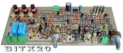
5 Farhan's BITX20
6 Bi-directional Amplifiers Vin/Rin = Vout/Rf (Eq.1) 1) The voltage gain, and the input and output Ie = Vin / Re = Vout / Rl (Eq. 2) impedances are all related to resistor values and do not Vout / Vin = Rf / Rin = Rl / Re. (Eq. 3) depend upon individual transistor characteristics. We only assume that the transistor gain is sufficiently high Rf / Rin = Rl / Re. (Eq 4) throughout the frequencies of our interest. The precise value of the transistor characteristics will only limit the upper frequency of usable bandwidth of such an amplifier. This is a useful property and it means that we can substitute one transistor for another. 2) The power gain is not a function of a particular transistor type. We use much lower gain than possible if the transistor was running flat out. But the gain is controlled at all frequencies for this amplifier. This means that this amplifier will be unconditionally stable (it won't exhibit unusual gain at difference frequencies). 3) You can restate the eq 3 as Rf * Re = Rl * Rin. That would mean that for a given fixed value of Rf and Re, the output impedance and input impedances are interdependent. Increasing one decreases the other and vice versa! For instance, in figure 1, Rf = 1000, Re = 10, if we have Rin of 50 ohms, the output impedance will be (1000 * 10)/50 = 200 ohms. Conversely, if we have an Rin of 200 ohms, the output impedance will be 50 ohms!
7 BITX20 History Farhan VU2ESE BITX20 Design based on EMRFD topics (1Q2004) Farhan's Web Site for BITX20 ( Hans G0UPL Discussion Group (June 2004) ( Parts Kits Arv K7HKL Discussion Group (July 2004)

8 Farhan VU2ESE Multi-Band BITX Single Band BITX Tsunami Interview on CNN DC Receiver Test Equipment


9 Hans G0UPL BITX20 Parts Kits BITX Discussion Group QRP, QRSS, QRO, Etc. Test Equipment Minimalist Frequency Counters Homebrew Spectrum Analyzer Huff & Puff VFO Stabilizer Designs Polyphase Receiver Design GPS Based Frequency Standard

10 Arv K7HKL Early BITX20 Builder Early BITX40 Builder Early BITX-1750 Builder BITX Discussion Group BITX20A Prototype Kit Builder BITX17A Prototype Verification Builder Authored the BITX20A Kit and BITX17A Kit Assembly Manuals
11 Raj VU2ZAP Mentored VU hams building BITX20 Helped hams worldwide resolve technical problems via contributions to the discussion group Provides very strong encouragement and support for ham radio in India, and worldwide
12 Rahul VU3WJM Provided help via the discussion group in resolving technical problems Designer of the BITX20 Version-3 Kits


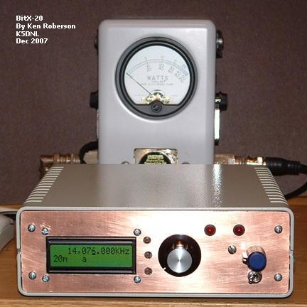
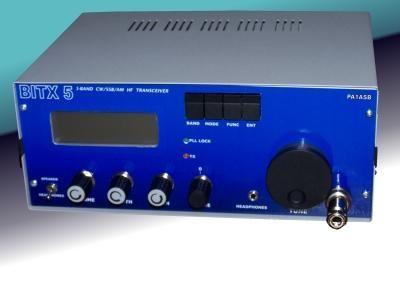
13 Early BITX20 Transceivers Farhan VU2ESE Hans G0UPL Peter W6JFR/N6QW BITX20/PSK Rudd PE2BS


14 Sunil VU3SUA BITX20 Version-3 PCB & Coils Partial Kits BITX Ver-3 Full Kits Counter Kit Case Kit

 BITX Case Kit (Ken")
15 Doug KI6DS Funded BITX20A Kit prototyping & testing BITX20A Kit Digital Dial (Steve KD1JV) BITX17A Kit (Nigel G0EBQ) BITX Case Kit (Ken WA4MNT) NORCAL FCC-1/2 DDS Kit

16 Dan N7VE Tayloe Detector NORCAL NC-2030 Tayloe SWR Bridge BITX20A Kit Design Push-Pull RF PA Improved Audio FCC Compliance PCB Layout
17 Jim K8IQY NORCAL 2N2-xx 2N2/6 No-tune Xvtr SW-30 CW 30M Xcvr IOWA 10M CW Xcvr BITX20A Kit Prototype Build & Testing Varactor tuned VFO (no air capacitors) RF Bandpass Filter Rework
18 Significant Contributions Martien PE1BWI - RF PA Stabilization Modification Chris PA2CRX Modification to keep RF out of audio stages Wes W7ZOI EMRFD & Bi-directional Amplifiers Leonard KC0WOX How-To Videos, BITX V-3 Assembly Manual, Fixing Inoperative BITXs Nigel G0OEP BITX17A Conversion
19 BITX20 Discussion Group Over 2000 Active Members Worldwide Adding About 6 New Members Per Week 8000 Messages Posted Tight Focus on BITX and BITX-related Issues We Have No Idea How Many BITX Transceivers Have Been Built Hams Helping Hams
20 BITX Today Many Ugly-Construction & homebrewed PCB BITXs have been built, and more continue to be built 4 Kit Vendors BITX20A, BITX17A, Chassis & Counter Kits Doug KI6DS - BITX20 Ver-3, Chassis & Counter Kits Sunil VU3SUA - MKARS-80 Kit, Chassis Kit Original BITX20 Bare PCB


21 Some BITX's


22 More BITX's
23 BITX Tomorrow... New Versions & New Modifications SDR Computer Control & Computer Interface Linear Amps For Higher Power Output. SB & CW Versions, With Adjustable Bandwidth Multi-Band Versions AVC, AGC & VOX Modifications ICs Replacing Discrete Components A BIPH, or Phasing BITX Is Being Designed
24 BIPH Phasing Transceiver Uses Mostly BITX Circuitry Direct-Conversion Layout Single-Band, With Band Conversion Information QRP Power Levels (Target = 10 Watts) Passive Polyphase AF Phase Shifting LC or -3db Hybrid Type RF Phase Shifters...? Huff & Puff Stabilized VFO Digital Dial (AVR Microprocessor & LCD) Timetable...When It Is Ready...


25 Phasing Transceiver Design Issues
Hendricks QRP Kits BITX20A SSB Transceiver Assembly, Testing, and Operation. Part 1
 Hendricks QRP Kits BITX20A SSB Transceiver Assembly, Testing, and Operation Part 1 Arv K7HKL This article documents assembly, testing and operation of the Hendricks QRP Kits BITX20A SSB transceiver. This
BITX20 - A Bidirectional SSB transceiver - By Ashhar Farhan
 HAM NEWS JUNE - JULY 2004 PAGE 1 BITX20 - A Bidirectional SSB transceiver - By Ashhar Farhan An easy to build 6 watts SSB transceiver for 14MHz BITX is an easily assembled transceiver for the beginner
: Hacking Bitx Version3B, C: : 20mt to 40mt band: PART I
 : Hacking Bitx Version3B, C: : 20mt to 40mt band: PART I Fig 1: Bitx Ver3C SBL-1 20 Conversion for Bitx40 The picture in Fig1 is a Bitx3C SBL-1 for 40mt band, constructed from the Bitx Version 3C SBL-1
Modernization of QRP RADIOS and Development of the QCX transceiver Hans Summers G0UPL
 Modernization of QRP RADIOS and Development of the QCX transceiver Hans Summers G0UPL http://qrp-labs.com Introduction and 3 topics Introduction to the QCX transceiver Three topics: 1. Improving QRP radio
Group build proposal Michael G3WOE
 Group build proposal Michael G3WOE MISSION A 10 radio for Whitton Members BITX Group build project A new mission with a worthwhile and tangible outcome. To provide a new practical focus for the club meetings.
A Termination Insensitive Amplifier for Bidirectional Transceivers
 A Termination Insensitive Amplifier for Bidirectional Transceivers Wes Hayward, w7zoi, and Bob Kopski, k3nhi. 26 June 09 (converted to HTML on 27Dec09) The BITX-20 was the first of a now popular class
Does Your Receiver have an IQ?
 Does Your Receiver have an IQ? A Brief Presenta-on of how Radio Receivers have Evolved over the Decades of Radio, and Describing how some Modern SDR Receivers work using the Quadrature Sampling Detector,
Hendricks QRP Kits BITX20A to BITX17A Conversion Instructions
 Hendricks QRP Kits BITX20A to BITX17A Conversion Instructions 30 November 2008 Converting your BITX20A Kit to a BITX17A Kit is not all that complex. It only requires that you change crystals and some resonance
KWM-2/2A Transceiver THE COLLINS KWM-2/2A TRANSCEIVER
 KWM-2/2A Transceiver Click the photo to see a larger photo Click "Back" button on browser to return Courtesy of Norm - WA3KEY THE COLLINS KWM-2/2A TRANSCEIVER Unmatched for versatility, dependability and
RM Italy KL-500 PA.
 Frequency HF Input energy/power 10-34 A Input power 1-15 W Input power SSB 2-30 W Output power 300 W Max Output power SSB 600 W PEP Max Mode AM-FM-SSB-CW Fuse 3x12 A Output power level 6 Size 170x295x62
ILER-40 AGC "ADD-ON" MINI-MODULE Last review November 1, 2012
 ILER-40 AGC "ADD-ON" MINI-MODULE Last review November 1, 2012 ea3gcy@gmail.com Latest updates and news: www.qsl.net/ea3gcy PLEASE READ ALL INSTRUCTIONS COMPLETELY AT LEAST ONCE BEFORE STARTING. Installation
A homebrew QRP Transceiver. Lots of Fun & Lessons Learnt
 A homebrew QRP Transceiver Lots of Fun & Lessons Learnt Background In 2008 I was transferred to a new location. I could bring 2 suitcases along and spent 5 months in an apartment until the container with
Development of the QSX transceiver kit
 Development of the QSX transceiver kit Norfolk Amateur Radio Club Wednesday 9-Jan-2019 Hans Summers, G0UPL http://qrp-labs.com QCX 5W CW transceiver kit QRP Labs CW Xcvr Introduced at YOTA 2017 summercamp
HF SIGNALS ΜBITX. The QRP HF General Coverage Transceiver you can build. Buy Now Circuit Description Wireup Tune Up Help and Support BITX Hacks
 Page 1 of 5 HF SIGNALS ΜBITX The QRP HF General Coverage Transceiver you can build Buy Now Circuit Description Wireup Tune Up Help and Support BITX Hacks ($109 USD) Page 2 of 5 The µbitx is a general coverage
HT-1A Dual Band CW QRP Transceiver. Kit Building Instructions
 HT-A Dual Band CW QRP Transceiver Kit Building Instructions Rev B, July 8, 08 Designed by BD4RG Exclusively distributed by CRKITS.COM and its worldwide distributors Join the group http://groups.io/g/crkits
BP-1A. Band-Pass variable filter continuous tuning from 3 to 30MHz. For analogue or software-defined receivers (SDR) Assembly manual
 Assembly manual") BP-1A Band-Pass variable filter continuous tuning from 3 to 30MHz. For analogue or software-defined receivers (SDR) Assembly manual Last updated: December 1, 2017 ea3gcy@gmail.com Updates and news at:
BP-1A Band-Pass variable filter continuous tuning from 3 to 30MHz. For analogue or software-defined receivers (SDR) Assembly manual Last updated: December 1, 2017 ea3gcy@gmail.com Updates and news at:
SSB-MITE Assembly Manual. Copyright David Cripe NM0S The 4 State QRP Group. Introduction
 SSB-MITE Assembly Manual Copyright 2017 David Cripe NM0S The 4 State QRP Group Introduction Thank you for purchasing a SSB-MITE. We hope you will enjoy building it and find it a useful addition to your
Assembly Manual V1R2B-Rev1.0D
 Assembly Manual V1R2B-Rev1.0D for 4 State QRP MagicBox - Solid State Transmit/Receive System Designed by: Jim Kortge, K8IQY Copyright 2009-2012 - All rights reserved This system is the result of some brainstorming
75 Meter SSB Project Design by KD1JV Built by Paul Jorgenson KE7HR NSS 39382FE
 75 Meter SSB Project Design by KD1JV Built by Paul Jorgenson KE7HR NSS 39382FE After completing a 75 meter DSB project (and using it underground, caving), I wanted to try building a SSB rig. I was searching
Techniques for Passive Circuit Analysis for. State Space Differential Equations
 Techniques for Passive Circuit Analysis for chp4 1 State Space Differential Equations 1. Draw circuit schematic and label components (e.g., R 1, R 2, C 1, L 1 ) 2. Assign voltage at each node (e.g., e
RFIC DESIGN ELEN 351 Session4
 RFIC DESIGN ELEN 351 Session4 Dr. Allen Sweet January 29, 2003 Copy right 2003 ELEN 351 1 Power Amplifier Classes Indicate Efficiency and Linearity Class A: Most linear, max efficiency is 50% Class AB:
4/30/2012. General Class Element 3 Course Presentation. Practical Circuits. Practical Circuits. Subelement G7. 2 Exam Questions, 2 Groups
 General Class Element 3 Course Presentation ti ELEMENT 3 SUB ELEMENTS General Licensing Class Subelement G7 2 Exam Questions, 2 Groups G1 Commission s Rules G2 Operating Procedures G3 Radio Wave Propagation
NC2030 Dan Tayloe, N7VE; Trevor Jacobs, K6ESE
 NC2030 A high performance, low power, image rejecting DC transceiver for either 20 or 30m Dan Tayloe, N7VE; Trevor Jacobs, K6ESE Front View 20m Prototype SCAF Tune CW Speed Volume Keyer Program Main Tuning
The New England Radio Discussion Society electronics course (Phase 4, cont d) Introduction to receivers
 Introduction to receivers") The New England Radio Discussion Society electronics course (Phase 4, cont d) Introduction to receivers AI2Q April 2017 REVIEW: a VFO, phase-locked loop (PLL), or direct digital synthesizer (DDS), can
The New England Radio Discussion Society electronics course (Phase 4, cont d) Introduction to receivers AI2Q April 2017 REVIEW: a VFO, phase-locked loop (PLL), or direct digital synthesizer (DDS), can
An Experimental Polyphase Receiver by Bozidar Pasaric 9A2HL, Croatia Introduction
 An Experimental Polyphase Receiver by Bozidar Pasaric 9A2HL, Croatia Introduction The Tayloe receiver is a new type of digital SSB and single-sided CW RX, invented and patented by Dan Tayloe, N7VE. It
Design and Layout of a X-Band MMIC Power Amplifier in a Phemt Technology
 Design and Layout of a X-Band MMIC Power Amplifier in a Phemt Technology Renbin Dai, and Rana Arslan Ali Khan Abstract The design of Class A and Class AB 2-stage X band Power Amplifier is described in
SPECIFICATIONS: Subcarrier Frequency 5.5MHz adjustable, FM Modulated +/- 50KHz. 2nd 11MHz >40dB down from 5.5MHz
 Mini-kits AUDIO / SUBCARRIER KIT EME75 Version4 SPECIFICATIONS: Subcarrier Frequency 5.5MHz adjustable, FM Modulated +/- 50KHz Subcarrier Output 1.5v p-p Output @ 5.5MHz DESCRIPTION & FEATURES: The Notes
144MHz direct conversion receiver with I/Q outputs for use with Software Defined Radio.
 144MHz direct conversion receiver with I/Q outputs for use with Software Defined Radio. Overview This design is a direct conversion receiver for 144MHz with quadrature outputs for use either with a software
QRP Adventures. for Education, Challenge & Enjoyment. 7 Sept 2007, W2NED
 QRP Adventures for Education, Challenge & Enjoyment 7 Sept 2007, W2NED QRP -- Not Just For CW Although tonight s focus is on CW (because, that s what I do ) Much of the discussion also applies to SSB,
Ham Radio 101 SOARA Workshop 3 Stage General Purpose Amplifier By Hal Silverman WB6WXO SOARA Education Director
 Ham Radio 101 SOARA Workshop 3 Stage General Purpose Amplifier By Hal Silverman WB6WXO SOARA Education Director Several months ago I started to put together a workshop where students could breadboard and
D. W.Knight 1981, 1987, 2013, 2015.
 -i- + 1987 supplement Model 950AF Ultrasonic Receiver with Audio Filter Models T800 mk II, T900X and T900V Ultrasonic Transmitters Design and Pre-production Development D W Knight BSc, PhD, Oct 1987 b
The ROSE 80 CW Transceiver (Part 1 of 3)
") Build a 5 watt, 80 meter QRP CW Transceiver!!! Page 1 of 10 The ROSE 80 CW Transceiver (Part 1 of 3) Build a 5 watt, 80 meter QRP CW Transceiver!!! (Designed by N1HFX) A great deal of interest has been
Build a 5 watt, 80 meter QRP CW Transceiver!!! Page 1 of 10 The ROSE 80 CW Transceiver (Part 1 of 3) Build a 5 watt, 80 meter QRP CW Transceiver!!! (Designed by N1HFX) A great deal of interest has been
Albert F. Peter AC8GY Aug. 12, 2010
 Albert F. Peter AC8GY Aug. 12, 2010 Software-defined not software-controlled radio Most of the complex signal handling uses DSP User interface through the computer Usually some form of direct conversion
Arizona ScQRPion QRP Club. Ft Tuthill w DC CW Transceiver for 80m Part 1 of 2. by Dan Tayloe, N7VE. Ft Tuthill Page 1 of 31
 Arizona ScQRPion QRP Club Ft Tuthill 80 2.5w DC CW Transceiver for 80m Part 1 of 2 by Dan Tayloe, N7VE Page 1 of 31 Table of Contents Specifications... 4 Specifications... 4 Receiver... 4 Transmitter...
1. What is the unit of electromotive force? (a) volt (b) ampere (c) watt (d) ohm. 2. The resonant frequency of a tuned (LRC) circuit is given by
 volt (b) ampere (c) watt (d) ohm. 2. The resonant frequency of a tuned (LRC) circuit is given by") Department of Examinations, Sri Lanka EXAMINATION FOR THE AMATEUR RADIO OPERATORS CERTIFICATE OF PROFICIENCY ISSUED BY THE DIRECTOR GENERAL OF TELECOMMUNICATIONS, SRI LANKA 2004 (NOVICE CLASS) Basic Electricity,
Department of Examinations, Sri Lanka EXAMINATION FOR THE AMATEUR RADIO OPERATORS CERTIFICATE OF PROFICIENCY ISSUED BY THE DIRECTOR GENERAL OF TELECOMMUNICATIONS, SRI LANKA 2004 (NOVICE CLASS) Basic Electricity,
LnR Precision, Inc. 107 East Central Avenue, Asheboro, NC
 LD5 CW/SSB QRP Transceiver Quick guide manual Description: At the development base of the digital signal processing unit, an algorithm is embedded for IQ processing of the channels with phase suppression
Almost Synthesis: An Offset PLL with a Reference Divider.
 Almost Synthesis: An Offset PLL with a Reference Divider. Wes Hayward, w7zoi, updated 5 Dec 2011,14jan13, 6Jan15(minor edit) This note deals with an extremely simple Phase Locked Loop (PLL) frequency synthesizer.
S-Pixie QRP Kit. Student Manual. Revision V 1-0
 S-Pixie QRP Kit Student Manual Revision V 1-0 Introduction The Pixie 2 is a small, versatile radio transceiver that is very popular with QRP (low power) amateur radio operators the world over. It reflects
ALX-SSB 5 Band Filter Assembly Manual 19 November 2018
 ALX-SSB 5 Band Filter Assembly Manual 19 November 2018 Contents Theory of Operation:... 1 Figure 1... 2 Parts Included:... 4 Board Overview:... 5 Figure 2... 5 Figure 3... 5 Board Assembly:... 6 Cable
NC2030 Dan Tayloe, N7VE; Trevor Jacobs, K6ESE
 NC2030 A high performance, low power, image rejecting DC transceiver for either 20 or 30m Dan Tayloe, N7VE; Trevor Jacobs, K6ESE Front View 20m Prototype SCAF Tune CW Speed Volume Keyer Program Main Tuning
N7VE LED SWR Bridge Hendricks QRP Kits
 N7VE LED SWR Bridge Hendricks QRP Kits A simple, rugged and lightweight SWR bridge by Dan Tayloe, N7VE Page 1 of 10 Table of Contents Kit Parts... 3 Building the LED SWR bridge... 3 RF step up transformer...
CW-ADD. Universal CW Adapter for SSB Transceivers. Assembly manual. Last updated: October 1,
 CW-ADD Universal CW Adapter for SSB Transceivers Assembly manual Last updated: October 1, 2017 ea3gcy@gmail.com Updates and news at: www.ea3gcy.com Thanks for building the Universal CW Adapter kit CW-ADD
BITX40 with Raduino - tips and mods
 BITX40 with Raduino - tips and mods Also check out hfsigs blogspot http://bitxhacks.blogspot.co.uk/ Clicks during tuning I assume you are talking about the Raduino clicking as you tune. I'm not having
JUMA-TRX2 DDS / Control Board description OH2NLT
 JUMA-TRX2 DDS / Control Board description OH2NLT 22.08.2007 General Key functions of the JUMA-TRX2 DDS / Control board are: - provide user interface functions with LCD display, buttons, potentiometers
WSPR Audio Signal Source
 WSPR Audio Signal Source A stand-alone WSPR signal source that generates audio WSPR tones to drive a SSB transmitter or transceiver. Features: - Internal timing or NMEA GPS timing for UTC synchronization
The Walford Electronics Ford Receiver Kit Project Construction Manual
 The Walford Electronics Ford Receiver Kit Project Construction Manual Walford Electronics Ford Receiver construction manual V1.5 Page 1 of 22 Introduction The Ford receiver has four stages: The first stage
KN-Q10 Assembly Manual
 KN-Q10 Assembly Manual Translated by Adam Rong, BD6CR/4 with permission from Ke Shi, BA6BF Edited by Stephen, VK2RH Revision B, Oct 14, 2010 Thank you for purchasing the KN-Q10 4 Band SSB/CW Dual Mode
Analog RF Electronics Education at SDSMT: A Hands-On Method for Teaching Electrical Engineers
 Analog RF Electronics Education at : A Hands-On Method for Teaching Electrical Engineers Dr., Professor Department of Electrical and Computer Engineering South Dakota School of Mines and Technology (whites@sdsmt.edu)
Weekend VHF/UHF Power Amplifier
 www.svet-el.si/english AX elektronika d.o.o. Špruha 33 1236 TRZIN SLOVENIA Magazine publisher tel.: 00386 1 549 14 00 tel.:00386 1 528 26 88 fax: 00386 1 528 56 88 prodaja04@svet-el.si www.svet-el.si Weekend
Radio Receivers. Al Penney VO1NO
 Radio Receivers Al Penney VO1NO Role of the Receiver The Antenna must capture the radio wave. The desired frequency must be selected from all the EM waves captured by the antenna. The selected signal is
Analog & Digital Communication
 Analog & Digital Communication UNIT I Tuned Radio Frequency Receiver Outline Basic Receiver TRF block diagram Advantages Disadvantages Basic receiver -1 Basic receiver -2 If there are many stations then
Beta-test ED1 PCB installed in I0CG s K1
 K1 SSB Modification (Ed.2) This description provides the receiver (RX) modifications, assembly, alignment and operation as a first step. In a second step you can add the remaining transmitter (TX) modifications,
General Class License Theory II. Dick Grote K6PBF
 General Class License Theory II Dick Grote K6PBF k6pbfdick@gmail.com 1 Introduction In the first theory class we talked about basic electrical principles and components. Now we will build on this to learn
Some Thoughts on Electronic T/R Circuits
 Some Thoughts on Electronic T/R Circuits Wes Hayward, w7zoi, November 3, 2018 Abstract: Several schemes have been used to switch an antenna between a receiver and transmitter. A popular scheme with low
BLOCK DIAGRAM - I J Li) N 6. w IS) AF D RIVE R R F D RIVE R R F P OWE R AMP PL L OSC UNIT. LL co X X X Lti X. C X W N O C..) 4 C.
 N 6. w IS) AF D RIVE R R F D RIVE R R F P OWE R AMP PL L OSC UNIT. LL co X X X Lti X. C X W N O C..) 4 C.") MODEL 1-632 BLOCK DIAGRAM tl LL co a. LL O ox X X X X < X C.) W N C U) LL CO aa 1.11 t O - I J Ul Li) Lti N w IS) 1 X. C X Ir t AF D RIVE R X - LL C.) CD r.--1111 MOP U) N N 6 PL L OSC UNIT R F D RIVE
MODEL 1-632 BLOCK DIAGRAM tl LL co a. LL O ox X X X X < X C.) W N C U) LL CO aa 1.11 t O - I J Ul Li) Lti N w IS) 1 X. C X Ir t AF D RIVE R X - LL C.) CD r.--1111 MOP U) N N 6 PL L OSC UNIT R F D RIVE
ssb transceiver single-band using the LM373 communications IC
 single-band ssb transceiver using the LM373 communications IC How to use the versatile LM373 and several other ICs to build a compact ssb transceiver for 14 MHz About two years ago a new products announcement
Connecting the FCC-2 to the Hendricks DC Kits Bob Okas, W3CD
 Connecting the FCC-2 to the Hendricks DC Kits Bob Okas, W3CD This is an application note that describes how you can connect the NorCal FCC-1/2 combination to the DC kits. It involves a few extra components
AN IMPROVED SHORTWAVE REGENERATIVE RECEIVER
 AN IMPROVED SHORTWAVE REGENERATIVE RECEIVER Ramón Vargas Patrón rvargas@inictel-uni.edu.pe INICTEL-UNI Sensitivity and selectivity are issues that will invariably concern a short wave listener when he
Reconstructing my Hallicrafters SX-28A. John Staples, W6BM
 February 2017 Reconstructing my Hallicrafters SX-28A John Staples, W6BM I say reconstructing instead of recapping because in my youthful ignorance, I took a perfectly good receiver, stripped it and rebuilt
CX7 Troubleshooting Index
 CX7 Troubleshooting Index Modification S/1 Newsletter Guide Board Description A/TO A/TO MODE Intermod V1,12 P4.4 A11 Shut off one 35 MHz osc in receive, done sn 244 A/TO Spur V1,12 P1 Reduce A/TO spur,
LED S METER CONSTRUCTION MANUAL. LED S meter Construction Manual Issue 1.0 Page 1
 LED S METER CONSTRUCTION MANUAL LED S meter Construction Manual Issue 1.0 Page 1 Important Please read before starting assembly STATIC PRECAUTION The LED S Meter kit contains components which can be damaged
FT-897 Alignment. Local Oscillator Adjustment. PLL Adjustment
 FT-897 Local Oscillator Adjustment Reference Frequency Adjustment a. Connect a frequency counter to TP1032. b. Adjust the trimmer capacitor (TC5001) for 67.875000MHz ±5Hz on the frequency counter. c. Connect
LD5 CW/SSB QRP Transceiver SDR /DSP
 LD5 CW/SSB QRP Transceiver SDR /DSP Quick guide manual Description: At the development base of the digital signal processing unit, an algorithm is embedded for IQ processing of the channels with phase
ICOM IC-201 Allmode Transceiver
 ICOM IC-201 Allmode Transceiver Alignment Procedure Please note: This procedure is reengineered by myself and may be not in accordance with the original procedure from the manufacturer! So I can t accept
Technician License Course Chapter 3. Lesson Plan Module 7 Types of Radio Circuits
 Technician License Course Chapter 3 Lesson Plan Module 7 Types of Radio Circuits The Basic Transceiver Combination of transmitter and receiver Abbreviated XCVR (X = trans) Antenna switched between transmitter
Home Page Power Supply Local Oscillator Dividers Op Amps BPF(s) Mixer Comments
 Mixer Comments") Page 1 of 6 IV - Op Amps Stage Schematic Home Page Power Supply Local Oscillator Dividers Op Amps BPF(s) Mixer Comments Theory of Operation This stage amplifies the quadrature audio frequency difference
Page 1 of 6 IV - Op Amps Stage Schematic Home Page Power Supply Local Oscillator Dividers Op Amps BPF(s) Mixer Comments Theory of Operation This stage amplifies the quadrature audio frequency difference
Building a Bitx20 Version 3
 Building a Bitx20 Version 3 The board can be broken into sections and then built and tested one section at a time. This will make troubleshooting easier as any problems will be confined to one small section.
HARRIS 222 AMPLIFIER. Details and Modifications Ron Marosko, K5LLL
 HARRIS 222 AMPLIFIER Details and Modifications Ron Marosko, K5LLL HARRIS CH 11 Amp The Harris Channel 11 amplifier is a brother to the one used by many on 6M. It is capable of 1 KW output and uses a nominal
SEA INC OF DELAWARE PRELIMINARY MAINTENANCE MANUAL EXCERPTS CONCERNING TUNEUP MF/HF SSB GMDSS RADIOTELEPHONE/DSC CONTROLLER MODEL SEA 245
 SEA INC OF DELAWARE PRELIMINARY MAINTENANCE MANUAL EXCERPTS CONCERNING TUNEUP MF/HF SSB GMDSS RADIOTELEPHONE/DSC CONTROLLER MODEL SEA 245 (c) Copyright 2001 SEA, Inc. All rights reserved. SEA, Inc. 7030
The Icom IC Adam Farson VA7OJ. A New Top-class HF/6m Transceiver. IC-7700 Information & Links
 The Icom IC-7700 A New Top-class HF/6m Transceiver Adam Farson VA7OJ IC-7700 Information & Links Copyright 2008 North Shore Amateur Radio Club NSARC HF Operators IC-7700 1 IC-7700 front panel This is a
Minimalist Discrete Hi-Fi Preamp
 Minimalist Discrete Hi-Fi Preamp Rod Elliott (ESP) Introduction A preamp designed for the minimalist, and having no frills at all is the design goal for this project. It is designed as a preamp for the
The station must include a transmitter and receiver that can operate on the CW and voice segments of 40 meters. The TAK-40 covers 7.0 to 7.3 MHz.
 INTRODUCTION The TAK-40 transceiver is designed specifically for the ARRL Homebrew Challenge contest. The following is a list of the criteria for the contest and a brief description of how the TAK-40 meets
LBI-30398N. MAINTENANCE MANUAL MHz PHASE LOCK LOOP EXCITER 19D423249G1 & G2 DESCRIPTION TABLE OF CONTENTS. Page. DESCRIPTION...
 MAINTENANCE MANUAL 138-174 MHz PHASE LOCK LOOP EXCITER 19D423249G1 & G2 LBI-30398N TABLE OF CONTENTS DESCRIPTION...Front Cover CIRCUIT ANALYSIS... 1 MODIFICATION INSTRUCTIONS... 4 PARTS LIST AND PRODUCTION
Glossary of VCO terms
 Glossary of VCO terms VOLTAGE CONTROLLED OSCILLATOR (VCO): This is an oscillator designed so the output frequency can be changed by applying a voltage to its control port or tuning port. FREQUENCY TUNING
KACHINA 1 SSB TRANSCEIVER
 KACHINA 1 SSB TRANSCEIVER THEORY OF OPERATION The Kachina 1 Amateur Band Transceiver is a highly sophisticated, state of the art, piece of communication equipment, housed in the smallest of packages. Yet,
12kHz LIF Converter V2.43 9Mhz version
 12kHz LIF Converter V2.43 9Mhz version Please Note: This document supersedes all previously released documents and drawings on the LIF subject. This is the latest and most up-to-date document at this time.
Radio Receivers. Al Penney VO1NO
 Radio Receivers Role of the Receiver The Antenna must capture the radio wave. The desired frequency must be selected from all the EM waves captured by the antenna. The selected signal is usually very weak
Maintenance Manual. ORION UHF (Dual Bandwidth) SCAN AND SYSTEM MOBILE RADIO. ericssonz LBI TABLE OF CONTENTS
 SCAN AND SYSTEM MOBILE RADIO. ericssonz LBI TABLE OF CONTENTS") Maintenance Manual ORION UHF (Dual Bandwidth) SCAN AND SYSTEM MOBILE RADIO TABLE OF CONTENTS Synthesizer/Receiver/Exciter....... LBI-39163 Power Amplifier.............. LBI-39164 PA Interface................
Maintenance Manual ORION UHF (Dual Bandwidth) SCAN AND SYSTEM MOBILE RADIO TABLE OF CONTENTS Synthesizer/Receiver/Exciter....... LBI-39163 Power Amplifier.............. LBI-39164 PA Interface................
ERICSSONZ LBI-30398P. MAINTENANCE MANUAL MHz PHASE LOCKED LOOP EXCITER 19D423249G1 & G2 DESCRIPTION TABLE OF CONTENTS
 MAINTENANCE MANUAL 138-174 MHz PHASE LOCKED LOOP EXCITER 19D423249G1 & G2 TABLE OF CONTENTS Page DESCRIPTION... Front Cover CIRCUIT ANALYSIS...1 MODIFICATION INSTRUCTIONS...4 PARTS LIST...5 PRODUCTION
Stand Alone VXO (SAVXO) Assembly Manual Manual Version 1.0B_
 Assembly Manual Manual Version 1.0B_") Stand Alone VXO (SAVXO) Assembly Manual Manual Version.0B_0-6-0 Designed by: Jim Kortge, K8IQY Kitted & Sold by: 4 State QRP Group Copyright: 0 Forward Thank you for purchasing a 4 State QRP Group Stand
Stand Alone VXO (SAVXO) Assembly Manual Manual Version.0B_0-6-0 Designed by: Jim Kortge, K8IQY Kitted & Sold by: 4 State QRP Group Copyright: 0 Forward Thank you for purchasing a 4 State QRP Group Stand
Demo Circuit DC550A Quick Start Guide.
 May 12, 2004 Demo Circuit DC550A. Introduction Demo circuit DC550A demonstrates operation of the LT5514 IC, a DC-850MHz bandwidth open loop transconductance amplifier with high impedance open collector
Preliminary features of the SDR-X receiver SDR-X , PowerSDR Winrad Winrad DDS SFDR SFDR AD995 AD99 1
 Preliminary features of the SDR-X receiver The SDR-X receiver, in its full version is capable of continuously tuning the entire HF spectrum, 6m ( 50-52 MHz) band included. SSB, AM etc. demodulation, bandpass
WSPR Audio Signal Source v2.0
 WSPR Audio Signal Source v2.0 A stand-alone WSPR signal source that generates audio WSPR tones to drive a SSB transmitter or transceiver. Features: - Internal timing or NMEA GPS timing for UTC synchronization
The KW 76A MOBILE RECEIVER
 The KW 76A MOBILE RECEIVER The KW 76A Receiver is designed primarily for mobile operation. The compact layout makes it particularly suitable for under dash mounting in a vehicle. When used at a Home station
SOUTHERN AVIONICS COMPANY. SE125 Transmitter. SE125 Transmitter 1-1
 1-1 1 Introduction The SE Series transmitters are computer controlled systems designed around an embedded microprocessor. These systems are capable of remote monitoring and maintenance via Ethernet (optional).
IQ+ XT. 144Mhz SDR-RF Exciter (preliminar v0.1)
") IQ+ XT 144Mhz SDR-RF Exciter (preliminar v0.1) INTRODUCTION Since the IQ+ receiver was introduced one year ago several people ask if I have plans to produce an IQ+ transmitter. Initially I didn't plan
IQ+ XT 144Mhz SDR-RF Exciter (preliminar v0.1) INTRODUCTION Since the IQ+ receiver was introduced one year ago several people ask if I have plans to produce an IQ+ transmitter. Initially I didn't plan
Transceiver selection and Specs.
 Transceiver selection and Specs. Transceivers 1956-2018 From TUBES to SDR Covers 20-10 meters in 100Khz segments, 10 available, crystal needed for each. Plug in crystal holder. 100 Watts output, final
ASSEMBLY MANUAL FOR R3500D DIRECTION FINDING RECEIVER KIT
 SDR-Kits www.sdr-kits.net SDR-Kits is CRKITS Authorised Distributor for Europe ASSEMBLY MANUAL FOR R3500D DIRECTION FINDING RECEIVER KIT Rev. A May 24, 2015 Written by CRKITS http://www.crkits.com Thanks
Process Components. Process component
 What are PROCESS COMPONENTS? Input Transducer Process component Output Transducer The input transducer circuits are connected to PROCESS COMPONENTS. These components control the action of the OUTPUT components
ericssonz LBI-38640E MAINTENANCE MANUAL FOR VHF TRANSMITTER SYNTHESIZER MODULE 19D902780G1 DESCRIPTION
 MAINTENANCE MANUAL FOR VHF TRANSMITTER SYNTHESIZER MODULE 19D902780G1 TABLE OF CONTENTS Page DESCRIPTION........................................... Front Cover GENERAL SPECIFICATIONS...................................
- have been successfully combined in the RCA -developed insulated -gate metal -oxide -
 A PUBLICATION OF RCA ELECTRONIC COMPONENTS AND DEVICES VOL. 27, NO. 3 1967, RADIO CORPORATION OF AMERICA OCTOBER, 1967 Using the MOS Field -Effect Transistor As a Product Detector and AGC Gate By W. M.
Introduction Introduction to radio frequencies p. 3 What are the 'radio frequencies'? p. 3 Why are radio frequencies different? p.
 Foreword p. xi Preface p. xiii Introduction Introduction to radio frequencies p. 3 What are the 'radio frequencies'? p. 3 Why are radio frequencies different? p. 3 What this book covers p. 3 Signals and
Instructions MODIFICATION KIT MODEL SBM - 1O2-1 INTRODUCTION PARTS LIST FOR THE
 Instructions FOR THE MODIFICATION KIT MODEL SBM - 1O2-1 INTRODUCTION This modification Kit applies to the following Heath Transceivers: 1. All Models HW-100, SB-100, SB-101 and SB-101W. 2. Any Model SB-102
Fundamentals of Microelectronics. Bipolar Amplifier
 Bipolar Amplifier Voltage Amplifier Performance Metrics - There are many metrics that are used to evaluate how good an amplifier is (1) (Voltage) Gain= Vout/ Vin. Can be found from small-signal 10 8 6
HF, 6 m, 2 m and 0.7m SDR (Software Defined Radio) Receivers AR1 and AR2 Series -Make it Simple as Possible with Outstanding Performances, part1
 Receivers AR1 and AR2 Series -Make it Simple as Possible with Outstanding Performances, part1") HF, 6 m, 2 m and 0.7m SDR (Software Defined Radio) Receivers AR1 and AR2 Series -Make it Simple as Possible with Outstanding Performances, part1 Dipl.ing Tasić Siniša-Tasa YU1LM/QRP All rights reserved,
HF, 6 m, 2 m and 0.7m SDR (Software Defined Radio) Receivers AR1 and AR2 Series -Make it Simple as Possible with Outstanding Performances, part1 Dipl.ing Tasić Siniša-Tasa YU1LM/QRP All rights reserved,
ILER MK2. Appendices
 ILER MK2 QRP SSB Transceiver in Kit Form Appendices Last update: July 20, 2015 ea3gcy@gmail.com Most recent updates and news at: www.qsl.net/ea3gcy ILER-17 MK2 SSB QRP Transceiver Kit Page 1 APPENDIX 1:
Feedback and Oscillator Circuits
 Chapter 14 Chapter 14 Feedback and Oscillator Circuits Feedback Concepts The effects of negative feedback on an amplifier: Disadvantage Lower gain Advantages Higher input impedance More stable gain Improved
Copyright 2016, R. Eckweiler & OCARC, Inc. Page 1 of 8
 HOM rev. new Heathkit of the Month: by Bob Eckweiler, AF6C Heathkit of the Month #72 - HW-12/22/32 SSB Transceivers Pt. II AMATEUR RADIO - SWL Heathkit HW-12 / HW-22 / HW-32 Single-Bander SSB Transceivers
Building the Sawdust Regenerative Receiver
 Building the Sawdust Regenerative Receiver Introduction The Sawdust is a super regenerative receiver using the basic Armstrong design architecture. The receiver uses one toroidal transformer to provide
Linear IC s and applications
 Questions and Solutions PART-A Unit-1 INTRODUCTION TO OP-AMPS 1. Explain data acquisition system Jan13 DATA ACQUISITION SYSYTEM BLOCK DIAGRAM: Input stage Intermediate stage Level shifting stage Output