BLOCK DIAGRAM - I J Li) N 6. w IS) AF D RIVE R R F D RIVE R R F P OWE R AMP PL L OSC UNIT. LL co X X X Lti X. C X W N O C..) 4 C.
|
|
|
- Jerome Hunt
- 5 years ago
- Views:
Transcription
1 MODEL 1-632
2 BLOCK DIAGRAM tl LL co a. LL O ox X X X X < X C.) W N C U) LL CO aa 1.11 t O - I J Ul Li) Lti N w IS) 1 X. C X Ir t AF D RIVE R X - LL C.) CD r MOP U) N N 6 PL L OSC UNIT R F D RIVE R R F P OWE R AMP Qi, <I LL u: a; I W N O C..) 4
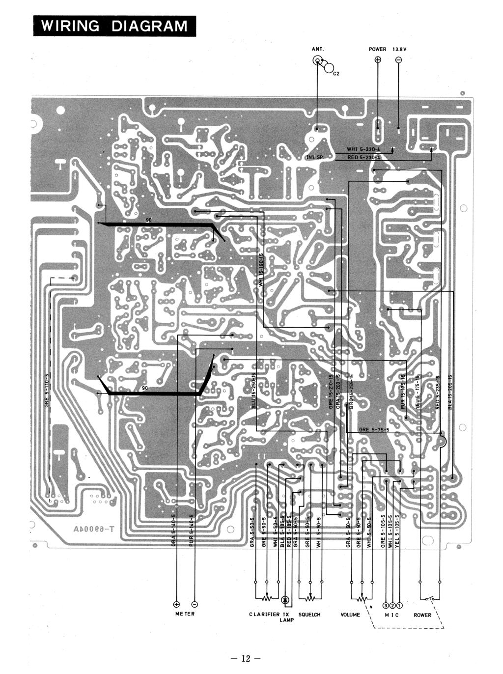
![PARTS LAYOUT TOP VIEW Atagai:7 ir1z]:](/docs-images/89/99384220/images/3-0.jpg "7411t: qi.1.141771itgimmorront.")
3 PARTS LAYOUT TOP VIEW Atagai:7 ir1z]: 7411t: qi itgimmorront... BACK VIEW
4
5 MODEL TRANSISTOR VOLTAGE CHART Vb (V) V (V) Ve (V) TX RX TX RX TX RX AM SSB AM SSB AM SSB AM SSB AM SSB AM SSB Q 1 2SC Q 2 2SC Q 3 2SC ,2 Q 4 2SC Q 5 2SC Li 1.1 Q 6 2SC Q 7 2SC Q 8 2SA Q 9 2SC Q1 1 2SC Q12 2SC Q1 3 2SC :37- Q14 2SB Q15 MPS Q16 2SD Q1 7 2SD NO SQUELCH SQUELCH Q1 8 2SC Q19 2S. C Q2 2SC
6 Vg (V) Vd (V) Vs (V) Tx Rx Tx Rx Tx Rx AM. SSB AM SSB AM SSB AM SSB AM SSB AM SSB Q19 2SK3A ' ' Vgl (V) Vg2 V) Vd (V) Vs (V) Tx Rx Tx Rx Tx Rx Tx Rx AM SSB AM SSB AM SSB AM SSB AM SSB AM SSB AM SSB AM SSB Q1 3SK IC1 M5122L Tx Rx PIN NO AM SSB No SQUELCH SQUELCH Tx 1C2 SL164C Rx Tx IC3 SL164C Rx 1C4 MC ' MODEL 1-632
7 1-632 Alignment Instruction RECEIVER 1. Testing Equipment to be used: *Power Supply 13.8VDC *Standard - Signal Generator *Low Frequency Voltmeter *Oscilloscope *8 ohms Dummy Load * Speaker *Microphone 1 set 1 set 1 set 1 set 1 pc. 1 pc. 1 pc. 2. Alignment Procedures: 1) Set the Mode Switch to AM, Volume Control at maximum, Squelch at minimum, Clarifier in the center and the CB-PA Switch to CB. 2) Set the SSG on Channel 19 and Channel Selector of the unit on Channel 19. Then, connect the Power Supply and 8 ohms Dummy Load to the transceiver unit. 3) Feed the signal from the SSG and set the audio output for a peak rding by adjusting T-1, T-2, T-3, and T-8. In this case be sure that antenna input should be less than 1 uv at the AF standard output power. Also, make sure that the audio on the oscilloscope is a sine wave 4) set the antenna input at 1 uv so that the antenna power may be more than.5 Watt at the maximum volume of all channels. 5) Set the antenna input at 1,,uV so that the output power should be more than 3.5 watts at the maximum volume. 6) Set the antenna input to 5,uV. and the low frequency output to.5watt by volume control. Then, decrease the antenne input until the low frequency output stays 1dB lower. Be sure that the antenna input then should be less than 5uV. 7) Set the antenna input to 1uV and the meter indication to 9 by VR4. 8) Set the volume control and squelch control at maximum, and set the tight squelch by VR2 so that the output from speaker is heard when the antenna input is increased upto 5uV. 9) Set the antenna input,to.7uv and be sure that the low frequency output should be over 1dB more when the modulation of the SSG is turned off at' the normal output. 1) Set the M ode Switch to USB, Volume Control at maximum, Squelch at minimum and Clarifier in the center. Tune off the modulation of the SSG and remove the frequency by 1 KHz. 11) Make sure that the maximum sensitivity shoud be less, than.2uv. 12) Make sure of AGC like with AM. 13) Set the antenna input to.15uv and keep the AF output to be over 1dB lower when the antenna input is turned off at the normal output. 3. PA Functioning: 1) Set the PA-CB Switch to PA. Connect the dummy load to PA Speaker Jack and microphone to Microphone Jack. 2) Make sure of the variation of the sound level with the volume control by pushing down the push-to-talk knob on the microphone.
8 1-632 Alignment nstruction 4. Reciver Alignment Specifications: AM: Maximum Sensitivity SSB: Low Frequency Output AGC Meter SQ S+N/N Maximum Sensitivity AGC Meter S+N/N less than 1 uv more than 3.5 Watts more than 8dB S9 at 1uV 5uV more than 1dB at.7uv less than.2uv more than 8dB S9 at 1uV more than 1dB at.15uv TRANSM ITTER 1. Connection of test equipment. *Power supply at 13.8VDC * Connect a Power meter, oscilloscope' frequency counter, spectrum analyzer and P-P RF volt meter to the RF output connector. *Connect an AF oscillator and AF volt meter to the microphone connector. 2. Power adjustment *Set the mode switch to AM. *Adjust T5, 4, 9, 1, 11 and T12, and L6 for the maximum point. *Adjust L4 for 3.6W output. *Adjust Ll to increase 2nd harmonic. 3. Frequency-Make sure every channel stays within ±8Hz. 4. Modulation Limiter Adjustment *Put in 1KHz and 5mV signal from AF oscillator and adjust VR7 for 9% modulation. 5. Modulation capability *Put in 1KHz signal by AF oscillator and get 9% modulation for the minus side. The plus side should be over 8%. 6. SSB *Set the mode switch to USB * Put in two-tone signal of 1 KHz and 1.6KHz by two AF oscillators. *Adjust T6 and T7 for the maximum point. 7. ALC alignment *Adjust the two-tone signal of AF oscillator for 3W RF power output. *Adjust VR5 for 11W PEP RF power output when the two-tone signal is increased by 2dB. 8. Carrier suppression *Cut off the two-tone signal and make sure the output level of the carrier is below -4dB. *Set the mode switch to LSB and do the same. Ser. 1 MODEL I -632 PRINTED IN JAPAN
9
10 C2/11,/ v Ii goce PLL- LOCK
FT-897 Alignment. Local Oscillator Adjustment. PLL Adjustment
 FT-897 Local Oscillator Adjustment Reference Frequency Adjustment a. Connect a frequency counter to TP1032. b. Adjust the trimmer capacitor (TC5001) for 67.875000MHz ±5Hz on the frequency counter. c. Connect
200GTL ALIGNMENT REVISION: 1.0 BURKE MODEL: 200GTL REVISION: 1.2 DATE: 02/14/06. Total Pages: 6 pages. Page:1 print date: 9/23/09
 ALIGNMENT PROCEDURE MODEL: 200GTL REVISION: 1.2 DATE: 02/14/06 PREPARED BY: BURKE Total Pages: 6 pages Page:1 print date: 9/23/09 1 TEST CONDITION: 200GTL ALIGNMENT INSTRUCTION 1.0. TEST TEMPERTAURE: 77
Preliminary Information (There will be updates)
") This Manual is provided by CBTricks.com Someone who wanted to help you repair your equipment put together this information. Cobra150GTL DX If you would like to help us put more manuals online support us.
This Manual is provided by CBTricks.com Someone who wanted to help you repair your equipment put together this information. Cobra150GTL DX If you would like to help us put more manuals online support us.
Frequency Coverage MHz RF Power Output 30W SSB / 9W AM/ 30W FM Dual Finals on Heat Sink Modes AM, FM, USB, LSB Microprocessor
 MAGNUM M-257 30W AM/ /FM/SSB 10--11 Meterr Mobile Trranscei ivverr n Prri iiccee: : US$ 250..00 eexx ssttoocckk JJaakkaarrttaa (Arrrri ( iivvi iinngg 2 d weeeekk iinn i Maarrcchh) ) SPECIFICATIONS Frequency
TS-590S ADJUSTMENT. Updating the Firmware. Required Test Equipment. Preparation
 Updating the Firmware The firmware of the main MCU and DSP can be updated using the TS590 Update update software. Update the firmware according to the procedure displayed in update software. Refer to the
Operation Manual. SlJPER ST AR Channel Mobile 5-Mode Transceiver -----~- --:.. KTSS200NXX ,, I
 Operation Manual!.,, SlJPER ST AR 2000 200 Channel Mobile 5-Mode Transceiver -----~- --:.. KTSS200NXX General Description l Frequency/Channel Chart The Super Star -2000 is a combination transmitter-receiver
ACCESSORY CIRCUITS ALIGNMENT
 UNIDEN 22 ACCESSOY CICUITS ALIGNMENT 1. NOISE BLANKE Adjustment 11. Test Equipment equired (1) DC Voltage Meter 12. Adjustment Procedures. (1) Set MODE SWITCH to USB, and recive 14.2 Mhz. (2) Activate
Second Hand Yaesu FTDX5000MP HF base station transceiver
 263 Walsall Road, Great Wyrley, Walsall, WS6 6DL Established 1997. Open Monday - Friday 9am - 5pm and Saturday 9.30am - 4pm Tel: 01922 414 796 Fax: 01922 417829 Skype: radioworld_uk Second Hand Yaesu FTDX5000MP
Yaesu FT-8800R Alignment
 DUAL BAND FM TRANSCEIVER Introduction and Precautions The FT-8800R has been carefully aligned at the factory for the specified performance across the 144 MHz and 430 MHz amateur bands. Realignment should
ICOM IC-201 Allmode Transceiver
 ICOM IC-201 Allmode Transceiver Alignment Procedure Please note: This procedure is reengineered by myself and may be not in accordance with the original procedure from the manufacturer! So I can t accept
hallicrafters PERFORMANCE SPECIFICATIONS MODEL: SR-2000 LATEST REVISION: 18 JAN 66 Code ident # Specification #
 hallicrafters PERFORMANCE SPECIFICATIONS MODEL: SR-2000 LATEST REVISION: 18 JAN 66 Code ident # 26916 Specification # 093-002154 I. GENERAL A. Power input 117V 50-60 cycles from a source capable of delivering
Adjustment for IC-910H. Adjustment. Adjustment
 for IC-910H 30.2 MHz Level 430MHz 2 nd Lo (60.4MHz) Peak Setting the 60.4MHz Frequency the144mhz 1 st Lo Lock Voltage th430mhz 1 st Lo Lock Voltage 144MHz RX Peak/ Gain Band Peak Band Total Gain Sub- Band
NOTE FTDX9000 CAT OPERATION REFERENCE BOOK FTDX9000 OPERATING MANUAL
 NTE FTD9000 CAT PERATIN REFERENCE BK FTD9000 PERATING MANUAL CAT (CMPUTER AIDED TRANSCEIVR) PERATIN VERVIEW The CAT (Computer Aided Transceiver) System in the FTD9000 provides control of frequency, VF,
SUPERSTAR TABLE OF CONTENTS AM/FM/USB/LSB/CW AMATEUR MOBILE TRANSCEIVER WITH BUILT-IN FREQUENCY COUNTER OWNER S MANUAL
 SUPERSTAR TABLE OF CONTENTS AM/FM/USB/LSB/CW AMATEUR MOBILE TRANSCEIVER WITH BUILT-IN FREQUENCY COUNTER PAGE CHAPTER 1 Specifications............................................... 2 CHAPTER 2 Installation.................................................
IC-400pro - RADIOAFICION.COM
 PROCEDURES IC-400pro - 5- PREPARATION When you adjust the contents on pages 5-5 and 5-6, SOFT- WARE, the optional CS-400PRO ADJ SOFTWARE (Rev..0 or later), *OPC- JIG CABLE (modified OPC- CLONING CABLE;
Midland 248XL I NSTRUCTION GUI DE
 Midland 248XL I NSTRUCTION GUI DE INDEX Introduction...2 Function and location of the controls...3 Installation...7 Power supply...7 Installing an antenna...7 How to use your Midland 248XL...8 Frequency
GRAND STRAND AMATEUR RADIO CLUB
 The GRAND STRAND AMATEUR RADIO CLUB (GSARC) Myrtle Beach SC is offering used amateur related equipment for sale. Written bids may be submitted to the GSARC up to Friday, November 23 rd, 2018. Only currently
DX AM FM SSB CW PA Amateur Base Station Transceiver OWNER S MANUAL RX / TX 2 4 POWER NF CHANNEL MODE RF POWER OFF CAL OFF OFF CALIBRATE
 1 2 3 6 4050 ULA 6070 TI 80 90 100 9 DX 2517 2517 RX / TX 0 2 4 SWR WATTS SET 81012 22 1 010 3 2030 5 MOD 7 ON dbover 9 SIGNAL +20 +40+60 PA FM AM USB LSB CW POWER ON SWR NB / ANL R.BEEP +10KHz NF CHANNEL
VvV MODEL-309 OWNER'S MANUAL. 40 channel CB Transceiver. Professional Quality And Performance Standards Advanced Circuitry With PLL Synthesis
 VvV MODEL-309 OWNER'S MANUAL 40 channel CB Transceiver Professional Quality And Performance Standards Advanced Circuitry With PLL Synthesis GENERAL INSTRUCTIONS Your model is an all solid-state SSB/AM
Beta-test ED1 PCB installed in I0CG s K1
 K1 SSB Modification (Ed.2) This description provides the receiver (RX) modifications, assembly, alignment and operation as a first step. In a second step you can add the remaining transmitter (TX) modifications,
OWNER'S MANUAL Channels All-Mode AM/FM/USB/LSB Built in Frequency Counter Mobile Transceiver with Roger Beep
 SUPER STAR 7QOODX OWNER'S MANUAL 3360 Channels All-Mode AM/FM/USB/LSB Built in Frequency Counter Mobile Transceiver with Roger Beep TABLE OF CONTENTS Page Specifications... 2 Installation Location... 4
OBJECTIVES EQUIPMENT LIST
 1 Reception of Amplitude Modulated Signals AM Demodulation OBJECTIVES The purpose of this experiment is to show how the amplitude-modulated signals are demodulated to obtain the original signal. Also,
Receiver Adjustments
 ! -8-4!5 This Section details procedures for tuning and adjustment of T2000 series II radios. This is normally only required during product manufacture or after major servicing. The following topics are
18-CHANNEL MOBILE CB TRANSCEIVER MODEL CB-845
 18-CHANNEL MOBILE CB TRANSCEIVER MODEL CB-845 INSTRUCTION HANDBOOK RAll JEFFERSOn CITIZEN BAND RADIO MESSAGE TO THE OWNER CONGRATULATIONS! As the new owner of Ray Jefferson Model CB-845 CB Mobile Transceiver,
The Uniden Grant XL Owners Site
 The Uniden Grant XL Owners Site Modifications page for the Grant XL (For Informational purposes only) The author of this site takes NO responsibility for illegal modifications and/or use of illegally modified
OPERATOR S MANUAL KYODO WEST MODEL KG506 FULL-DUPLEX MOBILE. Preliminary
 OPERATOR S MANUAL KYODO WEST MODEL KG506 FULL-DUPLEX MOBILE Preliminary 1.0 INTRODUCTION Thank you for purchasing the KYODO WEST MODEL KG506 Full-Duplex Mobile Radio. This manual contains information to
THEORY OF OPERATION. TM308EUL for Cobra Nov 06,2006
 THEORY OF OPERATION TM308EUL for Cobra Nov 06,2006 This PLL controlled VHF marine mobile transceiver provides an accurate and stable multi-channel operation. The transceiver consists of 15 main sections
KACHINA 1 SSB TRANSCEIVER
 KACHINA 1 SSB TRANSCEIVER THEORY OF OPERATION The Kachina 1 Amateur Band Transceiver is a highly sophisticated, state of the art, piece of communication equipment, housed in the smallest of packages. Yet,
MASTR II AUXILIARY RECEIVER 19D417546G7 & G8 & ANTENNA MATCHING UNITS 19C321150G1-G2. Maintenance Manual LBI-30766L. Mobile Communications
 L Mobile Communications MASTR II AUXILIARY RECEIVER 19D417546G7 & G8 & ANTENNA MATCHING UNITS 19C321150G1-G2 Printed in U.S.A Maintenance Manual TABLE OF CONTENTS Page SPECIFICATIONS.....................................................
FCC ID: AXI IC: 10239A Alignment
 Introduction The VX-261 is carefully aligned at the factory for the specified performance across the frequency range specified for each version. Realignment should therefore not be necessary except in
DX 2547 AM/ SSB Two Way Citizen Band Base Station Transceiver OWNER S MANUAL
 DX 2547 POWER S 1 3 20% 5 7 40% 9 60% +20 80% 100% +40 db +60 NORMAL 9 19 TALKBACK MOD PWR 0 SWR 1 3 1.5 6 2 9 AM / SSB Base Station CB Radio 3 12 15 MAX CHANNEL GNF R.B. PA USB AM LSB ANL NB OFF DX 2547
AM/FM/SSB/CW 12 & 10 METER MOBILE AMATEUR TRANSCEIVER OWNER S MANUAL
 AM/FM/SSB/CW 12 & 10 METER MOBILE AMATEUR TRANSCEIVER OWNER S MANUAL TABLE OF CONTENTS Warranty...2 Introduction...3 Installation... 4-5 Front Panel Controls... 6-8 Microphone...8 Menu Settings... 9-11
Youkits SK-1A 40m SSB/CW QRP Transceiver. Operating manual
 Youkits SK-1A 40m SSB/CW QRP Transceiver Operating manual Specifications Size: 88*38*124mm (not including knob, etc.) Weight: about 280g (not including battery pack) Supply voltage: 10-15VDC Current drain
KWM-2/2A Transceiver THE COLLINS KWM-2/2A TRANSCEIVER
 KWM-2/2A Transceiver Click the photo to see a larger photo Click "Back" button on browser to return Courtesy of Norm - WA3KEY THE COLLINS KWM-2/2A TRANSCEIVER Unmatched for versatility, dependability and
AC LAB ECE-D ecestudy.wordpress.com
 PART B EXPERIMENT NO: 1 AIM: PULSE AMPLITUDE MODULATION (PAM) & DEMODULATION DATE: To study Pulse Amplitude modulation and demodulation process with relevant waveforms. APPARATUS: 1. Pulse amplitude modulation
DX 93T OWNER S MANUAL. 10 Meter Amateur Mobile Transceiver With Built-in Frequency Counter & StarLite Face Plate TABLE OF CONTENTS CHAPTER 1 CHAPTER 2
 PAGE CHAPTER 1 Specifications.............................................. 2 Twin Turbine S 1 PW R 3 20 0 SW R 40 1 5 5 60 1.5 7 10 2 9 20 80 3 30 +20 40 50 DX 93T +40 100% MAX db +60 DX 93T B A SW R
LBI-31564A. Mobile Communications. DELTA - SX MHz RADIO COMBINATIONS (NEGATIVE GROUND ONLY) Maintenance Manual
 Maintenance Manual") A Mobile Communications DELTA - SX 136-174 MHz RADIO COMBINATIONS (NEGATIVE GROUND ONLY) Maintenance Manual TABLE OF CONTENTS MILITARY AND SYSTEM SPECIFICATIONS................................. 2-3 COMBINATION
A Mobile Communications DELTA - SX 136-174 MHz RADIO COMBINATIONS (NEGATIVE GROUND ONLY) Maintenance Manual TABLE OF CONTENTS MILITARY AND SYSTEM SPECIFICATIONS................................. 2-3 COMBINATION
DELUXE 18CHANNEL SSB/AM CB TRANSCEIVER OWNER'S GUIDE
 DELUXE 18CHANNEL SSB/AM CB TRANSCEIVER OWNER'S GUIDE General Description The Bush Ranger is a combination transmitter and receiver designed for use in the Australian 27 MHz Citizens radio service. It is
MFJ-752C SIGNAL ENHANCER II
 MFJ-752C SIGNAL ENHANCER II INTRODUCTION The improved MFJ-752C SIGNAL ENHANCER II is comprised of two tunable audio filtering systems designed to clarity and remove interfering signals from both voice
QRPver 20M Transceiver Review By Edward R. Breneiser, WA3WSJ
 QRPver 20M Transceiver Review By Edward R. Breneiser, WA3WSJ I was looking around for a door prize for the Boschveldt QRP Club MOC 2018 Event and found a unique QRP site. The website is QRPver.com and
Installation... 3 Installing The Radio... 3 Ignition Noise Interference... 4 Antenna... 4 External Speaker... 4 Public Address...
 TABLE OF CONTENTS CHAPTER 1 Specifications.............................................. 2 PAGE BIG RIG SERIES S 1 MOD PW R 20 0 3 SW R 40 1 5 5 60 1.5 7 10 2 9 20 80 3 30 +20 40 50 +40 100% MAX db +60
Using measurement methods described in Australian/New Zealand Standard AS/NZS 4770:2000
 Barrett 2050 HF transceiver Using measurement methods described in Australian/New Zealand Standard AS/NZS 4770:2000 General Specifications Equipment Standards Transmit frequency range Receive frequency
AM/FM 10 METER MOBILE AMATEUR TRANSCEIVER OPERATING MANUAL
 AM/FM 10 METER MOBILE AMATEUR TRANSCEIVER OPERATING MANUAL INTRODUCTION Congratulations on your purchase of a Magnum S-6 AM/FM 10 meter transceiver. Your Magnum S-6 is designed to provide years of enjoyment
RCI-6300F25/150. Owner's Manual. AM/FM Amateur Transceiver With Built-in Frequency Counter. Table of Contents. Downloaded from
 Table of Contents RCI-6300F25/150 AM/FM Amateur Transceiver With Built-in Frequency Counter PAGE Chapter 1 Specifications...... 2 Chapter 2 Installation...... 3 Installing the Radio... 3 Ignition Noise
CON NEX HP. OWNER'S MANUAL Full Channel AM/FM Amateur Mobile Transceiver TABLE OF CONTENTS TUNING THE ANTENNA FOR OPTIMUM S.W.R..
 TABLE OF CONTENTS PAGE SPECIFICATIONS... 2 INSTALLATION... 3 LOCATION... 3 CON NEX - 4300HP MOUNTING THE RADIO... 3 IGNITION NOISE INTERFERENCE... 4 ANTENNA... 4 TUNING THE ANTENNA FOR OPTIMUM S.W.R..
Maintenance Manual ERICSSONZ LBI-31552E
 E Maintenance Manual TONE REMOTE CONTROL BOARD 19A704686P4 (1-Frequency Transmit Receive with Channel Guard) 19A704686P6 (4-Frequency Transmit Receive with Channel Guard) ERICSSONZ Ericsson Inc. Private
DX 33HP. 10 Meter Amateur Mobile Transceiver OWNER S MANUAL. Download this Manual Free of Charge at
 DX 33HP SIG 1 3 TX PWR 5 7 9+30dB POWER HI NB/ANL MED LO HI LO BAND ECHO RX/TX VOL SQ MIC RF FM PA AM D/A E/B F/C ECHO TIME BAND 10 Meter Amateur Mobile Transceiver Download this Manual Free of Charge
LnR Precision, Inc. 107 East Central Avenue, Asheboro, NC
 LD5 CW/SSB QRP Transceiver Quick guide manual Description: At the development base of the digital signal processing unit, an algorithm is embedded for IQ processing of the channels with phase suppression
Cubic Astro 103 Restoration Notes
 Cubic Astro 103 Restoration Notes W7CPA February 2016 I restored a Cubic Astro 103 a few years ago and have enjoyed operating it for years. It s a very nice geezer wireless and the last amateur radio product
MAINTENANCE MANUAL TRANSMITTER/RECEIVER BOARD CMN-234A/B FOR MLSU141 & MLSU241 UHF MOBILE RADIO TABLE OF CONTENTS
 MAINTENANCE MANUAL TRANSMITTER/RECEIVER BOARD CMN-234A/B FOR MLSU141 & MLSU241 UHF MOBILE RADIO TABLE OF CONTENTS DESCRIPTION... 2 CIRCUIT ANALYSIS... 2 TRANSMITTER... 2 9-Voft Regulator... 2 Exciter...
Zeon PDF Driver Trial
 401 W. 35th Street, Suite B National City, CA 91950 (800)446-5778. FAX( 619)426-3788 Email : rci@rangerusa.com http : //www.rangerusa.com Printed In Malaysia AT6960A11B PD000619 TR-966 SOLID STATE CITIZENS
Hendricks QRP Kits BITX20A to BITX17A Conversion Instructions
 Hendricks QRP Kits BITX20A to BITX17A Conversion Instructions 30 November 2008 Converting your BITX20A Kit to a BITX17A Kit is not all that complex. It only requires that you change crystals and some resonance
Downloaded from
 TABLE OF CONTENTS Installation... 2 Location... 2 Mounting the Connection... 2 Ignition Noise Interference... 2 Antenna... 2 Tuning the Antenna for Optimum SWR... 3 External Speaker... 4 Replacing fuse...
ericssonz LBI-38640E MAINTENANCE MANUAL FOR VHF TRANSMITTER SYNTHESIZER MODULE 19D902780G1 DESCRIPTION
 MAINTENANCE MANUAL FOR VHF TRANSMITTER SYNTHESIZER MODULE 19D902780G1 TABLE OF CONTENTS Page DESCRIPTION........................................... Front Cover GENERAL SPECIFICATIONS...................................
A NEW LIFE FOR THE FT-290R TRANSCEIVER! By F5RCT
 A NEW LIFE FOR THE FT-290R TRANSCEIVER! By F5RCT The FT290R is an old amateur radio workhorse which was a very popular transceiver during the 80 s. It is a 2metre multimode portable which can run with
Exercise 2: FM Detection With a PLL
 Phase-Locked Loop Analog Communications Exercise 2: FM Detection With a PLL EXERCISE OBJECTIVE When you have completed this exercise, you will be able to explain how the phase detector s input frequencies
The 21st Century R-390A/URR Reference Y2K-R3 Edited 7/09: No Technical Changes Chapter 2 - Operation. Page Table Of Contents 2-1
 Edited 7/09: No Technical Changes Chapter 2 - Operation Page Table Of Contents 2-1 2.1 Introduction. 2-2 2.2 Controls and Indicators 2-2 2.3 Operating Instructions And Control Settings 2-9 2.3.1 Pre-operational
LD5 CW/SSB QRP Transceiver SDR /DSP
 LD5 CW/SSB QRP Transceiver SDR /DSP Quick guide manual Description: At the development base of the digital signal processing unit, an algorithm is embedded for IQ processing of the channels with phase
DX 99V OWNER S MANUAL. Full Channel AM/FM/SSB Mobile Built in Frequency Counter with Roger Beep
 WARRANTY This radio is covered by a two year limited parts and labor warranty. Limited means that we will repair problems caused by factory defects or normal use at no charge. Before returning a radio
2-Tone Audio Oscillator for SSB Tests
 2-Tone Audio Oscillator for SSB Tests Background This 2 Tone generator has been designed to provide 2 non-harmonically related signals as an audio source for testing SSB transmitters and associated equipment.
SB-36 OPERATION MANUAL
 SB-36 OPERATION MANUAL Remastered by NoobowSystems Lab. Tomioka, Japan 2003 Rev.00 http://www.noobowsystems.com PRELIMINARY VERSION NoobowSystems Lab. Tomioka, Japan 2003 http://www.noobowsystems.com/
SPECS FEATURES SUPPLIED ACCESSORIES. HF All Band Transceiver
 718 HF All Band Transceiver RX 0.030-29.999999MHz* TX 1.800-1.999999 MHz** 3.500-3.999999 MHz** 7.000-7.300000 MHz 10.100-10.150000 MHz 14.000-14.350000 MHz 18.068-18.168000 MHz 21.000-21.450000 MHz 24.890-24.990000
12kHz LIF Converter V2.43 9Mhz version
 12kHz LIF Converter V2.43 9Mhz version Please Note: This document supersedes all previously released documents and drawings on the LIF subject. This is the latest and most up-to-date document at this time.
The World Finest Wireless Systems
 The World Finest Wireless Systems www.toa.com.hk...within the broadcast, film, music, school, house of worship and theatre industries. S4.04 Series - 4 Channel Wireless System The S4.04 is Trantec s simplest
Code Master. Model CWR-610E OPERATING INSTRUCTIONS
 Code Master Model CWR-610E OPERATING INSTRUCTIONS CONTENTS RATING... 3 DESCRIPTION OF PANELS... 5 METHOD OF USE Preparation... 7 Reception of CW... 7 Code interpretable range and word space... 7 Reception
EXHIBIT 3 : FCC (c) (TEST DATA) AND FCC (MEASUREMENT PROCEDURES) INTRODUCTION TO TRANSMITTER MEASUREMENTS, Part 2.
 (TEST DATA) AND FCC (MEASUREMENT PROCEDURES) INTRODUCTION TO TRANSMITTER MEASUREMENTS, Part 2.") EXHIBIT 3 : FCC 2.1033(c) (TEST DATA) AND FCC 2.1041 (MEASUREMENT PROCEDURES) INTRODUCTION TO TRANSMITTER MEASUREMENTS, Part 2.1033(c)(14) Exhibits 4 through 9 on the following pages present the required
EXHIBIT 3 : FCC 2.1033(c) (TEST DATA) AND FCC 2.1041 (MEASUREMENT PROCEDURES) INTRODUCTION TO TRANSMITTER MEASUREMENTS, Part 2.1033(c)(14) Exhibits 4 through 9 on the following pages present the required
From German Radio Amateur Jochen Heilemann (DG2IAQ) Dragon SS-201 Version MHz AM/FM/SSB Handheld Transceiver, 4-6 Watts
 Dragon SS-201 Version MHz AM/FM/SSB Handheld Transceiver, 4-6 Watts") Introduction The beautiful handheld transceiver came with a very quiet and low modulation. The original FM deviation was only 1,5 khz on mine! With the FM deviation pot on maximum! Normally you should
Introduction The beautiful handheld transceiver came with a very quiet and low modulation. The original FM deviation was only 1,5 khz on mine! With the FM deviation pot on maximum! Normally you should
TABLE OF CONTENTS. Magnum International PO Box 445 Issaquah, WA 98027
 OPERATING MANUAL TABLE OF CONTENTS Limited Warranty... 2 Introduction... 3 Installation...3-4 Front Panel Controls and Functions...4-7 Other Features... 7 Specifications... 8 LIMITED WARRANTY Magnum International
Mastr III P25 Base Station Transmitter Tune-up Procedure
 Mastr III P25 Base Station Transmitter Tune-up Procedure 1. Overview The Mastr III Base Station transmitter alignment is performed in several steps. First, the Transmit Synthesizer module is aligned to
DX 979 OWNERS MANUAL. AM / SSB Two Way Citizens Band Mobile Transceiver With StarLite Face Plate TABLE OF CONTENTS CHAPTER 1 CHAPTER 2 CHAPTER
 TABLE OF CONTENTS DX 979 CHAPTER 1 Specifications................................................ 2 PAGE CHAPTER 2 Installation.................................................. 3 Installing The Radio..........................................
AR3000A SERVICE MANUAL TABLE OF CONTENTS PAGE SPECIFICATIONS (1)
") AR3000A SERVICE MANUAL TABLE OF CONTENTS PAGE SPECIFICATIONS ------------------------------------------------------- (1) BLOCK DIAGRAM--------------------------------------------------------- (2) THEORY
AR3000A SERVICE MANUAL TABLE OF CONTENTS PAGE SPECIFICATIONS ------------------------------------------------------- (1) BLOCK DIAGRAM--------------------------------------------------------- (2) THEORY
3 T856/857 Initial Tuning & Adjustment
 M850-00 T856/857 Initial Tuning & Adjustment C3.1 3 T856/857 Initial Tuning & Adjustment The following section describes the full tuning and adjustment procedure and provides information on: channel programming
SP980. Cordless Stereo 863MHZ. Speaker System. User s Manual INTRODUCTION FEATURES. Please read before using the equipment
 SP980 Cordless Stereo 863MHZ Speaker System INTRODUCTION This 863 MHz stereo wireless speaker system uses latest wireless technology that enables you to enjoy music and TV sound anywhere inside or outside
Zeon PDF Driver Trial
 401 W. 35th Street, Suite B National City, CA 91950 (800)446-5778. FAX( 619)426-3788 Email : rci@rangerusa.com http : //www.rangerusa.com Printed In Malaysia AT6960A11A PD000619 TR-936 SOLID STATE CITIZENS
IC-F7000. Advanced selective call and ALE make HF communication easier than ever!
 Page 1 of 5 HF TRANSCEIVER IC-F7000 Advanced selective call and ALE make HF communication easier than ever! The IC-F7000 is an HF land mobile transceiver especially designed forlong distance communications.
HAMTRONICS TB901 FM EXCITER INSTALLATION, OPERATION, & MAINTENANCE
 HAMTRONICS TB901 FM EXCITER INSTALLATION, OPERATION, & MAINTENANCE GENERAL INFORMATION. The TB901 is a single-channel low power fm transmitter (exciter) designed to provide 300-600 milliwatts continuous
FT-450/D. HF/50 MHz TRANSCEIVER. Technical Supplement. Introduction. Contents
 HF/50 MHz TRANSCEIVER FT-450/D Technical Supplement 2011 VERTEX STANDARD CO., LTD. EH024H90D VERTEX STANDARD CO., LTD. 4-8-8 Nakameguro, Meguro-Ku, Tokyo 153-8644, Japan VERTEX STANDARD US Headquarters
BEFORE YOU OPERATE THE HR-07-NZ 10 METER AMATEUR RADIO
 CONGRATULATIONS on your purchase of a HURACAN HR-07-NZ 10meter amateur radio. Your HURACAN HR-07-NZ transceiver radio is designed to provide trouble-free service and state of the art, high performance
Please read before using this equipment
 Please read before using this equipment DRAGON MODEL : SS-485H OWNER'S MANUAL 10 METER AM/FM/SSB MOBILE RADIO FEATURES Your SS-485H 10 Meter Amateur Transceiver is a two-way 28 MHz radio for use in your
MASTR II BASE STATION MHz RECEIVER IF/AUDIO/SQUELCH & RF ASSEMBLY (25 khz/12.5 khz CHANNEL SPACING) Maintenance Manual LBI-38506A
 Maintenance Manual LBI-38506A") A Mobile Communications MASTR II BASE STATION 806-824 MHz RECEIVER IF/AUDIO/SQUELCH & RF ASSEMBLY (25 khz/12.5 khz CHANNEL SPACING) TABLE OF CONTENTS RF ASSEMBLY, MIXER AND IF FILTER BOARD...... LBI-30482
A Mobile Communications MASTR II BASE STATION 806-824 MHz RECEIVER IF/AUDIO/SQUELCH & RF ASSEMBLY (25 khz/12.5 khz CHANNEL SPACING) TABLE OF CONTENTS RF ASSEMBLY, MIXER AND IF FILTER BOARD...... LBI-30482
Radio Station Setup and Electrical Principles
 Radio Station Setup and Electrical Principles Covers sections: T4A-T5D Seth Price, N3MRA February 20, 2016 Outline 4.1 Station Setup 4.2 Operating Controls 4.3 Electronic Principles 4.4 Ohm s Law 4.5 Power
The station must include a transmitter and receiver that can operate on the CW and voice segments of 40 meters. The TAK-40 covers 7.0 to 7.3 MHz.
 INTRODUCTION The TAK-40 transceiver is designed specifically for the ARRL Homebrew Challenge contest. The following is a list of the criteria for the contest and a brief description of how the TAK-40 meets
ANALOG COMMUNICATION
 ANALOG COMMUNICATION TRAINING LAB Analog Communication Training Lab consists of six kits, one each for Modulation (ACL-01), Demodulation (ACL-02), Modulation (ACL-03), Demodulation (ACL-04), Noise power
TMR6200 HF Naval Digital Transceivers
 TMR6200 HF Naval Digital Transceivers One or Two High Performance 500 W/1 kw Transceivers in a Single Cabinet 125 W High Performance Transceiver In a 4U/19-inch Chassis Outstanding RF Performance Optimized
Rockwell Collins, Inc. VHF Users Manual
 Rockwell Collins, Inc. VHF-2200 Users Manual This manual provided to the FCC for product guidance, it should not be used by our OEM customers. Scope: This document will detail information required to install
EMTtEmawaT OWNER' MANU EAT. NO TRC PLEASE READ BEFORE USING THIS EQUIPMENT CUSTOM MANUFACTURED FOR TANDY CORPORATION
 D EMTtEmawaT TRC-490-18 OWNER' MANU PLEASE READ BEFORE USING THIS EQUIPMENT EAT. NO. 1-9490 CUSTOM MANUFACTURED FOR TANDY CORPORATION Your REALISTIC TRC-490-18 is a completely solid-state AM/SSB Transceiver
PRC 320 Modifications Martin Ehrenfried G8JNJ
 PRC 320 Modifications Martin Ehrenfried G8JNJ I have deliberately not given specific cut wire here instructions, as the construction of the PRC320 does seem to vary considerably. This especially applies
VX-2100/VX-2200 (UHF) Alignment
 Alignment") VX-2100/VX-2200 (UHF) Introduction The VX-2100/2200 is carefully aligned at the factory for the specified performance across the frequency range specified for each version. Realignment should therefore
VX-2100/VX-2200 (UHF) Introduction The VX-2100/2200 is carefully aligned at the factory for the specified performance across the frequency range specified for each version. Realignment should therefore
Barrett 950 HF transceiver specifications Using measurement methods described in European Telecommunication Standard
 Barrett 950 HF transceiver specifications Using measurement methods described in European Telecommunication Standard 300 373. General Specifications Equipment Standards Transmit frequency range Receive
LED S METER CONSTRUCTION MANUAL. LED S meter Construction Manual Issue 1.0 Page 1
 LED S METER CONSTRUCTION MANUAL LED S meter Construction Manual Issue 1.0 Page 1 Important Please read before starting assembly STATIC PRECAUTION The LED S Meter kit contains components which can be damaged
MODEL AF200A: FM, FM/SCA RECEIVER/MONITOR OPERATION MANUAL
 MODEL AF200A: FM, FM/SCA RECEIVER/MONITOR OPERATION MANUAL THE AF200A IS AN FM AND FM/SCA PROFESSIONAL STYLE RECEIVER/ MONITOR. IT S MANY APPLICATIONS INCLUDE STATION MONITORING AND EAS MONITORING. The
Maintenance Manual TRANSMITTER/RECEIVER BOARD CMN-233 FOR MLSH041
 Maintenance Manual TRANSMITTER/RECEIVER BOARD CMN-233 FOR MLSH041 TABLE OF CONTENTS Page DESCRIPTION... 2 CIRCUIT ANALYSIS... 2 Transmitter... 2 9-volt Regulator... 2 Exciter... 2 40-Watt PA... 2 Antenna
Vectronics VC-300D DIGITAL BARGRAPH ANTENNA TUNER
 Vectronics VC-300D DIGITAL BARGRAPH ANTENNA TUNER FEATURES The Vectronics VC-300D Antenna Tuner optimizes the performance of your antenna and transmitter, receiver, or transceiver by providing adjustable
DX 73V OWNER S MANUAL FULL FEATURED AM/FM MOBILE TRANSCEIVER. WARRANTY This radio is covered by a two year limited parts and labor warranty.
 WARRANTY This radio is covered by a two year limited parts and labor warranty. Limited means that we will repair problems caused by factory defects or normal use at no charge. Before returning a radio
Maintenance Manual. MTD SERIES 900 MHz, 10-WATT, DATA ONLY MOBILE RADIO. Mobile Communications LBI TABLE OF CONTENTS
 Mobile Communications MTD SERIES 900 MHz, 10-WATT, DATA ONLY MOBILE RADIO TABLE OF CONTENTS RF BOARD............................... LBI-38545 AUDIO BOARD............................ LBI-38546 LOGIC BOARD............................
Construction Manual 6m-Linear-Transverter XV6/10
 Construction Manual 6m-Linear-Transverter XV6/10 Holger Eckardt DF2FQ Kirchstockacherstr. 33 D-85662 Hohenbrunn 2606 Technical data exciter frequency: 28... 30 MHz RF frequency: 50... 52 MHz supply voltage:
Construction Manual 4m-Linear-Transverter XV4-15
 Construction Manual 4m-Linear-Transverter XV4-15 Holger Eckardt DF2FQ Kirchstockacherstr. 33 D-85662 Hohenbrunn 3207 Technical data exciter frequency: 21.0... 21.5 MHz RF frequency: 70.0.. 70.5 MHz supply
User Manual. Specifications...3. Control and Operation Microphone...8. Installation...9. Installation of Main Unit...9
 Contents Specifications...3 Control and Operation...4-7 Microphone...8 Installation...9 Installation of Main Unit...9 Antenna Installation...9 Operational test...9 Frequency Bands Table...10 Frequency
Operation Manual. Model SG Elenco Precision Wide Band Signal Generator
 99 Washington Street Melrose, MA 02176 Phone 781-665-1400 Toll Free 1-800-517-8431 Visit us at www.testequipmentdepot.com Elenco Precision Wide Band Signal Generator Model SG-9000 Operation Manual CONTENTS
Analog S-Meter: Responsive mechanical meter gives accurate meaningful reports.
 Introduction Congratulations on choosing the MFJ-9475 75-Meter transceiver. At home or on the road, your MFJ-9475 is built to deliver performance you never thought possible from a low-power radio. Before