Electricity and Magnetism Experiments from Kits
|
|
|
- Roger Pitts
- 6 years ago
- Views:
Transcription
1 Electricity and Magnetism Experiments from Kits Peter Dourmashkin John G. King
2 Electricity and Magnetism Experiments from Kits Peter Dourmashkin Senior Lecturer in Physics Massachusetts Institute of Technology John King Francis Freidman Professor of Physics Massachusetts Institute of Technology
3 Contents Introduction Safety About Wire About Soldering Making Clip Leads CLK Exercise: The Multimeter MM Building the LVPS Low Voltage Power Supply Voltage, Current and Resistance Experiment VI Voltage, Current and Resistance Building the HVPS High Voltage Power Supply Experiment EF Electrostatic Force Experiment EB Electrical Breakdown Experiment MF Magnetic Force Building the AMP Amplifier Experiment MW Microwaves Red Box Contents and Kit Parts List
4 Introduction These are instructions for six basic experiments in electricity and magnetism that students assemble from kits, either in a lab, a dorm room or at home. There are also brief theoretical explanations. The level is suitable for use in an introductory course with calculus. The experiments are similar to ones developed at MIT beginning in 1988 and later at Caltech, and used there and elsewhere since. The E&M course with take-home kits in the initial MIT version has been described in ZAP! 1. The Caltech version, also called ZAP! is a published book 2. Also, the MIT instruction sheets for some 30 experiments in both E & M and mechanics have been collected and bound, Physics 8.01X (Fall) & 8.02X (Spring) Experiment Instructions 3. The remainder of this introduction is adapted from the foreword to that collection. It was once common for people, especially in their youth, to build model planes and boats and radios and audio amplifiers, etc., from kits, getting the pleasure of making something work from scratch. Not only did they get a strong practical sense of how things worked, but they also got much incidental knowledge about materials, fasteners, joining methods (glue and solder), miscellaneous articles of commerce (mostly from hardware and electronic parts stores), etc. This informal education enabled people to recognize items and methods when they saw them in the world and was valuable background for future experimenters and designers. This background was also valuable for the non-technical person who would not then, later in life, find the many surrounding technological devices entirely mysterious. Nowadays, people who have grown up with computers generally have had little contact with hardware, as was once commonplace. They have acquired a background of other valuable knowledge and skills. But both kinds of background are needed, not only fingers typing and the screen displaying, but also connecting components, so that current flows and things happen. Introductory physics as generally taught in high school and college, whether with classic set-piece labs, simulations, or MBL (or no lab) does little to develop the sort of manual and mental skills generated by doing hundreds of individually trivial actions and operations for example: stripping vinyl insulated number 22 tinned solid copper wire, bending it, and soldering it with a well tinned iron to another wire or a device terminal; or: breaking off a short piece of inch tungsten rod and pressing into the slot of a 4-40, 1/2 inch round-head brass screw, as for experiment EB. Providing kits, tools and instruments to do physics experiments at home or in the dormitory as part of the course, on an equal footing with problem solving, is one way to compensate for the lack of earlier experience of this kind. The experiments, about six or seven per semester, are designed to be assembled in one to two hours from 10 to 30 parts; running, getting data, analysis and presentation take another hour or two. They all yield quantitative results, and usually require graphing and sometimes error analysis. Generally the results are within ±10% of expected values (or better, for some experiments and some experimenters) good, considering the simple, low-cost materials and student inexperience (the latter often masked by well-engineered commercial apparatus in the standard teaching laboratory). For many of the experiments, everyone s results can be compiled, and a histogram of the values of, 1
5 for instance, ε 0, displayed in lecture. Mostly students work in pairs in construction and data taking, but keep individual notebooks and prepare separate short reports. Ideally the notebooks should be reviewed and commented on weekly, but this is hard to do with large groups. The partnership scheme has obvious advantages and troubles but generally works well enough. Whereas in the mechanics course time and temperature are read out with digital multimeters (they being no more mysterious than a stop watch or an A to D converter), in the E&M course analog multimeters are used. Besides enforcing the reading of a scale they can be gradually understood in every detail the d Arsonval movement, the range switch, shunts, multipliers, diodes in contrast to digital meters with chips and displays whose workings are hidden and harder to explain. Furthermore, low-cost digital meters, rated for 400V dc, can easily be destroyed by the over 1kV generated by the high voltage power supply. And, paradoxically, the limited selection of ranges of the low-cost analog meters is an advantage; it requires the use of external shunts and multipliers, so that knowledge of these useful topics, mostly gone from modern texts, is acquired in a natural way. The reader or student should be aware that many of the acronyms used here are not standard usage. Experiments are not numbered but are labeled with letters; power supplies are LVPS and HVPS; the analog multimeter, depending as it does on the torque on a coil in a magnetic field, is called MMM, magnetic multimeter (DMM for digital multimeter is standard). Contact with the real stuff that working with these kits provides is likely to be increasingly valuable as more and more complex equipment becomes available everywhere. It s not that 50 to 100 hours of this works will make anyone expert, but it s a beginning and one should be aware that a little knowledge [though] a dangerous thing is vastly better than none. Students who have worked with the kits say: they liked the chance to fool with stuff, it was gratifying to recognize components on computer circuit boards and in two cases, that they could, some years later, use the LVPS (10 of them in one case) in their research. 1. Philip & Phylis Morrison & John King, ZAP!: A Hands-On Introduction to Electricity and Magnetism (1991) [Available, as are kits, from KT Asssociates, 454 Hockomock Road, Woolwich, ME 04579]. 2. Jerry Pine, John King, Philip Morrison, Phylis Morrison, ZAP!: Experiments in Electrical Currents and Fields [Jones and Bartlett, Boston, 1996]. 3. J.G.King & A.P.French, Physics 8.01X (Fall) & 8.02X (Spring) Experiment Instructions (1998) [Available, as are kits, from KT Asssociates, 454 Hockomock Road, Woolwich, ME 04579]. 2
6 Safety The tools and kits provided for doing these experiments aren t dangerous, but you should take some reasonable precautions to avoid accidents. Watch out for fatigue. It s not good to see that it s 3 AM, and starting work on the experiment due the next day. You can work more or less effectively with computers, books and paper when tired or zonked; but you need to be alert when working with tools and devices so as not to hurt yourself. You also need to be carefully observant to coordinate the mind, the hands and the eyes as you follow instructions for assembling, testing and running the apparatus. Finally, analyzing and presenting the data you obtain needs greater attention and deeper thought than is usually required for much problem solving. Alertness, care and common-sense are basic to the safe use of tools. Think what would go wrong when the unexpected happens something slips or drops or lights fail, etc. Consider an extreme: using a chain saw be sure of your footing, imagine what happens if the saw bucks or the chain binds or breaks, know how to shut it off fast, wear glasses and hard hat and shoes. These are obvious what corresponds in your activities? You have a few sharp or pointed tools, and when you snip wires, scraps can fly around. Your soldering iron can burn you, char fabric, perhaps setting fire. When on and hot it should be in your hand, or on it s stand; unplugged and cool the rest of the time. Molten solder can drop on you with painful but not serious effect. Watch solder joints freeze and cool before touching. The danger from electric shock depends on the parts of the body that current passes through and on its magnitude. The magnitude of the current depends on the voltage and the sum of skin resistance and the internal resistance of the power supply. Skin resistance depends on moisture, area and pressure of contact, and if current flows, all sorts of effects from burning. You can get an idea of skin resistance with your multimeter on the RX1K range; here are typical results that you can check now or after you have done Exercise MM: Dry skin and light contact as much as 1 megohm or more Moist skin and firm contact as low as 50,000 ohms On the tongue as low as 5,000 ohms The National Safety Council lists as safe currents up to amperes (8 ma ). Currents less than 1mA are said to be not felt. Above 8 ma and up to 200 ma all kinds of bad things happen including burns, stopped heart and death. The most likely danger of shock in this work comes when you are plugging in your soldering iron or wall transformer hardly unusual or unfamiliar actions. The voltages around 12 volts of the transformer and the Low Voltage Power Supply that you will build present negligible hazard. The High Voltage Power Supply that you will build has an internal resistance 1
7 of about 700,000 ohms, so if you get across it with it turned up to 1,200 volts you might have about 2 ma passing through you hardly noticeable except as a weak burn if you allow it to arc to your finger; a feeling that disappears if you grab the contact firmly. Instructions that come with various products often contain long lists of warnings, against all sorts of dangers, some pretty far-fetched. These warnings, some reflecting a sort of paranoia, are there from a mix of concern for the well-being of the customer and fear of lawsuits when weird accidents happen. However, to stay safe, nothing takes the place of alertness, care and common sense. 2
8 About Wire Introduction There's a mind-boggling variety of wire available nowadays, probably thousands of kinds. Wire is made by drawing ductile metal bars through ever smaller holes in a succession of dies to produce the desired size. Much wire is used for mechanical purposes: wire rope, wirewrapped cannon barrels, picture wire, guy wires, spring wire, barbed wire, all mostly iron and steel and alloys. Practically every solid element in the periodic table is used as wire, pure or more often as an alloy, for a wide variety of purposes. Some common examples are lead wire for fuses and lead-tin alloys for solder, indium and gold for vacuum gaskets, platinum for electrodes and resistance thermometers. Most of the wire used for electrical conductors is made of copper or copper alloy, or aluminum. Electrical wire comes in diameters from inch (Wollaston wire, made by drawing down silver-clad platinum wire and then dissolving away the silver) up to about a half inch-- larger than that and its called `cable or `bar. The size is described by a "gauge" number according to the "American Wire Gauge" (AWG), a scheme in which the diameter of wire of each successively higher gauge number is less than the diameter of the previous one by a constant factor, the 39th root of 92 = The idea of a constant ratio between successive sizes comes naturally from the drawing process, and the particular choice of numbers, essentially arbitrary, provides enough wire sizes for many different uses, from power transmission to miniaturized electronics. (This constant ratio scheme is like the equally tempered musical scale, where each note is higher in pitch than the previous one by the 12th root of 2). Facts About Wire Number 2 copper wire weighs 0.2 pounds per foot and number 10 wire with a diameter of 0.10 inch has a resistance of about 1.0 ohms per 1000 feet. You can scale from this using the fact that an increase of three gauge numbers halves the area and weight and doubles the resistance. Increases of 6 and 10 gauge numbers approximately divides the area by 4 and 10, respectively. It's often important to know the current-carrying capacity of a particular wire, which depends on what kind of insulation it has, how hot it can get safely, and of course how well it's cooled. Cooling is complicated; heat must be conducted outward through the wire insulation, and then removed, mostly by convection, a process in which heated, less-dense fluid rises and is replaced by cooler stuff. Most electrical wire is insulated to prevent shorts, either by plastic or rubber or by a coating of "enamel", so-called because it's shiny like porcelain. Teflon, fiberglass and cotton are also used as insulation, and in the past, silk and asbestos were common. Data from the Handbook of Chemistry and Physics (HCP, 58th edition, p F-163) will give you an idea of the current-carrying capacity of bare copper wire: #12, 30 A; #14, 20 A; #18, 6 A. Plotting the current-carrying capacity versus area for these wires (and a few more) reveals the relations: I = 7.2 d 2 d in mm, I in A max 1
9 We can use this formula to compute current-carrying capacities-- not to be taken too seriously; if it smokes it's too much-- to put in the following table of wire properties. Gaug e Material Insulation Diameter ( mm ) Resistance per length at 20C ( Ω m ) Max Current ( A) Comments 30 Cu none Cu enamel tinned Cu plastic Solid & stranded as discussed 16 alloy none Used as shunt 14 Cu plastic house wire Comments On Wire You ll Use Red & black insulated #22 stranded tinned copper wire- This stranded #22 wire is made of 7 #30 wires, each covered with a thin layer of solder, ie. tinned, which makes it easy for you to solder it. Seven strands of #30 wires have the same area (within 10%), and hence about the same current carrying capacity as solid #22 wire. The plastic insulation is vinyl, a good insulator, but easily melted as you'll discover while soldering. Be careful when stripping off the insulation with wire strippers not to take along any of the wire strands; check by inspecting the removed piece of insulation. Stranded wire is more flexible and resistant to breaking than the corresponding solid wire. #16 resistance wire, made of a metal called "Alloy 800" by its manufacturer (MWS Wire Industries); it has a composition (in percentages) of 75 Ni, 20 Cr, 2.5 Al, 2.5 Cu. Number 16, diameter 1.3mm, has a resistance of 1.02Ω per meter. Contrast this with copper wire of the same gauge with a resistance of 0.013Ω m or with much thinner #30 with 0.34Ω m. In our experiments currents rarely exceed 1A and are usually much less, so voltage drops are unimportant. By putting the resistance wire in series in a circuit you can measure currents beyond the range of your multimeter simply by measuring the voltage drop across a measured length, and hence known resistance, of the wire. 2
10 Wires Found in Various Kits: Lengths of bare and insulated red & black #20 or #22 solid tinned copper wire Wire up circuits on perfboard (LVPS, HVPS, AMP) with this wire. Wherever there is no danger of shorts use bare wire; otherwise, red wire for positive leads, black wire for ground, common or negative leads. #30 bare copper wire This is used in Experiment EF (Electrostatic Force) to connect to the steel washer capacitor plates. Negligible current flows, and the flexibility of this thin wire minimizes mechanical disturbances. #26 enamel coated copper wire The insulating enamel, usually a dark brown, is a kind of plastic (urethane?). Use it to wind the coils used in Experiment MF (Magnetic Force). Except The enamel insulation must be removed to make electrical connection by soldering. Remove the enamel by careful sanding with the emery cloth or scraping with a knife or scissor blade; be careful not to weaken the wire by nicking it. There are solvents for enamel, nasty chemicals, and some people burn the enamel off with match, kind of a mess, also anneals and therefore weakens the wire. #14, 2-conductor with ground, house wire, called "NM", non-metallic sheathed By convention in house wiring, the black insulated wire is "hot", the white wire is the return near ground potential, and the bare wire is connected to ground, a buried metal water pipe for instance. This is to ground tools or appliances for safety so that internal electrical shorts or leakage to the metal case will not electrocute an operator who touches a grounded conductor, including moist earth. This wire, with the insulation pulled off, is used for transmitting and receiving dipole antennas in Experiment MW (Microwaves). #22 speaker wire This has two stranded #22 wires in a single clear plastic insulating sheath that can be split at the ends so that the wires can be individually stripped. It s a handy way to connect the transmitting antenna in Experiment MW (Microwaves) to the HVPS. Single-conductor or double-conductor shielded wire The shield is a tubular envelope of braided wire around the insulated inner conductor. With the shield grounded, charge and current that would be induced on the inner conductor by external electric fields are greatly reduced. It s used to connect the receiving dipole antenna in Experiment MW (Microwaves) to the AMP (Amplifier). It shields out lower frequency disturbances which the spark generating microwaves in Experiment MW makes. 3
11 Introduction About Soldering Making Clip Leads CLK In the course of these experiments, you will solder together wires and electronic components to make an adjustable regulated direct current power supply and other devices. Before you start doing the experiments, you and your partner will do three things involving soldering, namely: making two clip leads, putting alligator clips on the multimeter leads, and putting alligator clips on the wall transformer leads. Soldering is a way of joining metals with solder, an alloy that melts at about 180 o C (360 o F ). The hollow core of the wire solder in your tool kit contains a flux that cuts through oxide films on the surfaces of the metals so that the molten solder can wet and bond them. Soldering Iron Your tool kit contains a pencil type soldering iron. Plug it in and after 2 to 3 minutes, rub its conical tip with solder to tin it; that is, a film of molten solder wets it. Figure 1: Tinning the soldering iron The soldering iron in your toolkit requires some care. Once you have tinned the iron, you can clean the tip with a quick pass with a paper towel or emery cloth. It is important to keep your iron tinned otherwise oxides will form on the tip of the iron and the solder will not wet it. Unplug your soldering iron when not in use. Keep the soldering iron away from flammable materials. The tip of the iron gets very hot; be careful not to touch it. Soldering Wires To solder, put the iron up against the wires to be joined, letting the iron heat up the wires for a few seconds. Feed solder to the iron tip near the wires so that the molten solder can conduct heat to them and wet them. Smoke and vapors from this procedure are not harmful. Remove the 1
12 iron and let the solder solidify before moving the wires. The resulting joint should not come apart except with a very strong pull. Figure 2: Soldering Connections You should practice stripping (removing) the vinyl insulation from the ends of the stranded wire (in the clip lead kit), twisting the strands and tinning them with molten solder using your soldering iron. Then solder the two ends of the wires together. Try tugging them apart. Making Clip Leads Cut two pieces of vinyl-insulated stranded wire, about 300 mm (12 inch) long, one red, one black. You ll find wire in the Clip Lead Kit (CLK). You can use the wire cutter part of the long-nose pliers, or the wire strippers or scissors. Loosen the adjusting nut of the stripper, and set it so that the notch in the jaws just allows a regular paper clip to slide through. Wire is most easily stripped of its insulation by holding the wire with pliers with the part to be stripped protruding and then levering the wire strippers against the plier jaws. Try not to cut any of the strands. Remove about 4 mm (1/4 inch) of insulation from each end of each of the wires, and twist the strands into a compact bundle. 2
13 Figure 3: Stripping wires Tin all the ends, which means put solder on them with your iron so that the strands are bound together. Put two sleeves of the same color as the wire insulation on the wires, large end facing the wire ends. Make a right angle bend in the middle of the tinned part and put that through the hole in the end of the alligator clip from above (the side where there is a round pad to put your thumb when opening the jaws of the clip). Figure 4: Alligator clip Solder the tinned wire to the bottom side of the clip. You may find that it helps to hold the clip in your pliers using a rubber band around the handle of the pliers to give a firm grip. Let it all cool. Bend the insulated part back and crimp the end of the clip around it. Work the sleeve over the clip. Repeat three more times to make two clip leads. 3
14 Figure 5: Soldering clip leads Alligator Clips on Transformer Leads: In your Red Box you will find a Wall Transformer, that reduces the input 120V ac, 60 Hz (30 watt) from the line to a safe and convenient 12V ac 1 A output with only moderate loss of power (heating the transformer). It is IMPORTANT that the leads of the transformer should be of unequal length to reduce the likelihood of short circuits. If they are not, cut one of them so that it is about 50 mm (2 inches) shorter than the other. Put a black sleeve on each of the leads. Strip about 4 mm (1/4 inch) of insulation from each end of each of the leads. Solder on alligator clips as before. Putting Alligator clips on the Multimeter Leads: Whenever you want to make a measurement with your meter, you will use the red and black test leads. Your analog multimeter comes with test prods that have been removed. These prods would be useful in making quick measurements from point to point in some devices. They are not good for our purposes where we want to leave the meter connected for extended times. Put red and black sleeves on the appropriate leads. Solder on alligator clips as you did for clip leads. 4

15 Exercise MM About the Multimeter Introduction Our world is filled with devices that contain electrical circuits in which various voltage sources cause currents to flow. Electrical currents generate heat, light, and magnetic fields, and produce chemical effects. Any of these phenomena can be used to measure current. One of the simplest ways is to let the current flow through a coil of wire that is in a magnetic field and to measure the resulting torque on the coil by observing the deflection of a torsion spring. This is how your multimeter works, which we call a magnetic multimeter (MMM), in contrast to the standard term `analog. Look at the meter itself. You can see the copper colored coil and one of the two spiral torsion springs (the other is at the back; they also lead current in and out of the moving coil). The MMM is a current meter with a range selector switch, so that with appropriate resistors and other parts it can measure voltages and resistances. Figure 1: Coil and torsion spring A meter has a needle that moves clockwise in proportion to the current flowing through the meter. The needle goes over various scales above a reflecting mirror intended to reduce parallax error move your head so that you see the needle just above its reflection, and you ll be looking straight down onto the scale and be able to read the right number. In this exercise you will use your MMM to measure the resistance of a resistor, the voltage difference between the terminals of a AA cell (battery), and the current that flows in a simple circuit consisting of the battery and a resistor. The MM Kit contains one AA cell and one battery holder with a red lead (plus,+) and a black lead (minus,-). You may need to remove some of the insulation on the leads so that about 12in, 12 mm, of bare wire is exposed. Do this with the wire strippers in your toolkit. The kit 1
16 also contains two 20Ω resistors. You will also need one of the clip leads that you have just made. There is a separate package in the top tray of the Red Box containing two AA cells, and four 500 ma fuses. You should first open the back of the MMM and put in a 1.5V AA cell into the holder at the top of the MMM. Make sure the battery is placed with the + terminal connecting to the red wire. While the multimeter is open, notice that there is a fuse. If your multimeter is not working then there are two likely reasons. The first is that your test leads are broken or not making a good connection. The second reason is that the fuse may have blown. You have four spare fuses in your Red Box. The fuses may blow if you make a measurement with an inappropriate range selector setting, in particular the 250 DCA and Rx1 ranges. Measuring Voltage, Resistance and Current with the Multimeter Checking the MMM zero: With the MMM lying flat on a table or desk and with nothing connected look down so as to line up the needle and its image in the scale mirror. The needle should bisect the 4 black zeros. Tap or swing the meter; the needle should still show zero. If not, your 5mm flat screw driver will just about fit the adjusting screw in the lower center of the meter. Turn carefully until the needle sits on zero. Measure the resistance of the 20Ω resistor There are 3 resistance ranges, RX1, RX10, and RX1K (1K=1000). The ohmmeter operation depends on the 1.5V AA cell that is inside the meter. Essentially, current flows through the meter in inverse proportion to the resistance in the circuit. This accounts for the markedly non-linear green scale at the top of the meter. In order to zero the meter before measuring resistance, short the test leads by connecting them together. Then adjust the OHMS ADJUST knob (located to the left of center of the MMM) so that the meter reads 0 ohms; the needle is then at its maximum deflection. When the test leads are not connected, (an open circuit), no current flows and the needle sits on the infinite resistance mark,, all the way on the left side of the scale. Set the range selector switch on the MMM to the RX1 range. Connect the test leads to the resistor. Measure the resistance. You may want to make other resistance measurements. For example make a thick line with a lead pencil and measure the resistance of the mark. Grasp the clips firmly and see what your resistance is. Touch the clips to your tongue. Measure the voltage of the AA cell Set the range selector switch on the MMM to the 5 DCV range. Place the AA cell in the battery holder. Connect the test leads to the leads from the holder. Measure the voltage. 2
17 Measure the current in a simple circuit First set the range selector switch on the MMM to the 250m DCA range. Make a simple circuit consisting of the 20Ω resistor, the AA cell, and the MMM. You can do this by connecting the red lead of the MMM to the red lead (plus, +) of the AA cell holder. Use a clip lead to connect the black lead (minus, -) of the AA cell holder to one end of the 20 Ω resistor. Connect the black lead of the MMM to the other end of the 20Ω resistor. Measure the current in the circuit. What effect do you think the MMM has on the circuit? 3

18 About the Magnetic Multimeter Introduction The MMM will be one of your most important tools in this course. Please read the following explanation of the MMM. You may not be completely familiar with all the terminology. As the course develops, you will learn all the physical principles necessary to understand the MMM. So please keep on referring to the reading below if you have any questions about your MMM. Your analog multimeter (we call them MMM magnetic multimeters) is a moving coil meter with a needle whose deflection shows and measures the torque on a current loop placed in a magnetic field. That torque is proportional to the current, and a device that measures current is called an ammeter. The multimeter consists of a cylindrical magnet (magnetized across a diameter) arranged coaxially with a cylindrical magnetic return path as shown in Figure 2. Figure 2: Multimeter Coil In the gap is a pivoted rectangular coil; you can see the top of it if you look down into the meter. Spiral springs, top and bottom, lead current in and out of the coil and also provide a restoring torque. Jeweled bearings provide a low-friction mounting as in some watches. Current in the coil interacts with the radial magnetic field to generate tangential forces, and hence torques about the axis of rotation. These turn the coil until the magnetic torque is balanced by the torque of the spiral springs. The meter has a pointer or needle, which moves clockwise in proportion to the current flowing through the meter. The needle goes over various scales above a reflecting mirror intended to reduce parallax error move your head so that you see the needle just above its reflection, and you ll be looking straight down onto the scale and be able to read the right number. Any instrument that measure current will disturb the circuit under observation. (The coil itself has resistance.) There will be some voltage drop due to the resistance of the flow of current through the ammeter. An ideal ammeter has zero resistance, but a V drop is tolerable in our applications. 4
19 The range of an ammeter can be extended to measure higher currents by placing a resistor (called a shunt resistor) of resistance, R s, generally lower than the coil resistance, across the meter coil. When connected in a circuit with flowing current I, the meter will read a fraction of that current say 0.1 I, with 0.9 I passing through the shunt. The meter scale can be calibrated so that it reads 10 times its original range. To convert an ammeter into a voltmeter, a resistor (called a multiplier resistor) of resistance, R m, generally higher than the coil resistance, is put in series with the meter coil. Suppose a current I through the meter coil produces a full-scale (FS) reading, that is FS deflection of the needle. The coil resistance is R c, so the voltage across it, V = IR c. Putting a multiplier resistor R m = 9R c in series with the coil means that it will take 10 V to produce a FS reading, so we now have another range and can calibrate and label the scale accordingly. The ideal voltmeter should draw no current, corresponding to the zero voltage drop across the ideal ammeter. But in any moving coil meter currents produce torques which deflect springs and keep them deflected. Electrical power deflects the springs during the short time that the needle is moving and is also dissipated in the coil resistance as long as the needle is deflected. Test Leads The test leads are generally placed into the two pin jacks on the lower left of the MMM; black into COM and red into +V-Ω-A. Note the warning label that the inputs for these cannot exceed the maximum values of 500V DC, 1000V AC, 250mA DC (Figure 8). When you want to measure DC voltages up to 1000V, put the positive test lead into the pin jack labeled DC 1000V while leaving the black lead in COM. Range Selector Switch The meter can measure current, dc voltage, resistance, or ac voltage depending on the setting of the range selector switch. There are four types of positions: DCA for dc current, DCV for dc voltage, OHMS for resistance, and ACV for ac voltage. Each position has several ranges; for example OHMS has three ranges: RX1, RX10, and RX 1K. 5


20 Figure 3: Pin Jacks Figure 4: Range Selector Switch Scales There are four scales on the MMM. The top non-linear scale in green is used to measure resistance in ohms and ranges from to 0 reading left to right. Directly beneath the green scale is a red scale to measure AC. There are no markings on this scale. The black DC scale is divided into 10 large divisions over an angle of about 80 degrees; each large division is further divided into 5 small divisions. Alternate large divisions are labeled with 4 numbers. To the left, these are all zero. On the right are 5, 10, 25, 125; the voltage that produces full scale readings on the corresponding DCV range. Figure 5: Scales 6
21 For example, if you set your range selector switch to 25 DCV then each large division corresponds to 2.5V. When the needle points to full scale deflection, the voltage is 25V. (Notice that there is no 10V full scale switch setting.) When the switch is set to the 500 & 1K setting, each large division corresponds to 50V or 100V depending on which pin jack the positive lead is inserted into. The non-linear bottom scale (also in black) measures decibels (db), a logarithmic unit associated with sound level. This scale has the zero setting at 20 db and then ranges from 0 to 22 db moving from left to right. Current-Voltage Measurements DC current Ranges (DCA) First we ll consider the dc current ranges. DCA, ( DC stands for direct current), A stands for amperes so DCA means direct current amperage). There are two DCA current ranges, 250m and 50µ (250 mv). The more sensitive 50µ (250 mv) range can also be used to measure voltage. When the dial is set to 50 µ (250 mv) the resistance of the meter is 5000Ω. If the needle deflects to full scale, then 50µA flows through the meter. This corresponds to a voltage difference V = IR = (50µ A)(5000Ω ) = V = 250 mv. So this setting can measure voltages between 0V and 250 mv. Besides this most sensitive range, there is a 250 ma range marked 250mDCA. This puts in a 1Ω shunt resistor in parallel across the 5000Ω of the meter itself. Thus when current causes 250 mv to appear across the shunt and the 5kΩ meter resistance, a current of 250 ma passes through the shunt while 50µA passes through the meter giving full-scale deflection. Many of the MMM s have a fuse to protect the meter from overload on this range, otherwise the 1Ω resistor will burn out inside the meter. DC voltage Ranges (DCV) There are 4 DCV range switch positions 5, 25, 125, and 500 & 1K, selected by turning the range selector switch. DC stands for direct current, so DCV means direct current voltage. Selecting the various DCV ranges introduces more resistance in series. The resistance of the meter on any DCV range is always the full scale reading in volts times 20,000 ohms/volt [ Ω] [V ], a number that characterizes this meter as a dc voltmeter. For example, on the 25V setting, the resistance is R 25V = (25 V )(20,000 Ω V ) = 500k Ω= Ω. Table 1 shows the full scale value, the resistance of the meter on that range, and the power dissipated in watts through the meter for the DCV and DCA ranges. 7
22 Table One: resistance and power characteristics of DCV and DCA ranges on MMM Range Resistance in ohms [Ω] Power in milliwatts for full scale deflection [mw] 5V 100 k V 500 k V 2.5 M V 10 M V 20 M mV (50µ A) 5k mA The DCV range 500 & 1K is one range selector setting. When the positive test lead is in the +V-Ω-A, the full scale deflection corresponds to 500V. When the positive test lead is in the pin jack labeled DC 1000V, the full scale deflection corresponds to 1000V. AC voltage ranges (ACV) Suppose the ac input voltage is V( t ) = V 0 sin(2π ft ) where V 0 is the amplitude. A halfwave rectifier is inserted in series with the various resistors so that the ac has a dc component. The meter is insensitive to the fast variation of the output voltage across a load, so it will read the time averaged dc voltage V. Each ac scale is then calibrated by various resistors to indicate the root-mean square value V rms = V 0 2. For non-sinusoidal waveforms, or for ac superimposed on dc (average in time not zero), the readings of the meter will most likely not be meaningful. For ac you read the scales whose divisions and associated numbers are printed in red. Full-scale deflection corresponds to your choice of range for the root mean square voltage indicated on the rotary setting. At low voltages, the diode is not linear, (this is due to the small forward drop voltage) as can be seen from the small displacement of the red ac marks at the low end of the scale, from the corresponding black dc ones directly below. The resistance of the meter on any ACV range is always the full scale reading in volts time 10,000 ohms/volt, a number that characterizes this meter as an ac voltmeter. Resistance-Ranges (RX) There are 3 resistance ranges, RX1, RX10, and RX1K. The ohmmeter operation depends on the 1.5V AA cell that is inside the meter case. Essentially, current flows through the meter in inverse proportion to the resistance in the circuit. This accounts for the markedly non-linear green scale at the top of the meter. 8
23 In order to zero the meter, short the test leads by connecting them together. Then adjust the OHMS ADJUST knob (located to the left of center of the MMM) so that the meter reads 0 ohms; the needle is then at its maximum deflection. When the test leads are not connected, an open circuit, no current flows and the needle sits on the infinite resistance mark all the way on the left side of the scale. Half scale readings (that is with the needle pointing straight up parallel to the edge of the case) are: 24Ω, 240Ω and 24, 000Ω on the RX1, RX10, and RX1K ranges, respectively. Note also that on the resistance ranges the meter puts substantial current through the resistor being measured. Maximum currents are 0.05 A, 5 ma, and 50µA on the RX1, RX10, and RX1000 ranges, respectively. You can check out some of this by making measurements of one meter with another. Meter Damage Avoid dropping the meter. Keep its range switch on zero when it is not in use. This damps the motion of the coil and needle you can see this by rotating the case back and forth in a horizontal plane and comparing the needle motion with the switch on a voltage scale and on OFF. Or: set the meter on the RX1K, connect the test leads and note the time that the needle takes to return to zero when the leads are disconnected. Compare that time with the time it takes the needle to return to zero when the leads stay connected but the range is switched from RX1K to OFF. Besides the fuse, the moving coil is protected by resistors and a pair of back-to-back diodes across its windings. This means that it s hard to damage the meter coil except for the ranges with low resistance where resistors can be damaged by excessive currents (RX1 and 250mA ranges). However, it s good practice to start with high ranges, and not to measure the resistances of components that are wired into circuits, especially if power is on. Figure 6 shows the circuit diagram for multimeter. Notice that when the meter range selected is 50µ (250 mv), it takes 50µA in the external circuit to produce full scale deflection, but only 37µA flows through the coil of the meter. 9
24 Figure 6: Circuit diagram for MMM 10
25 Measuring Voltage, Resistance and Current with the Multimeter Measure the resistance of the 20Ω resistor Measure the voltage of the AA cell Measure the current in a simple circuit Measure the resistance of the 20Ω resistor: In order to zero the meter, short the test leads by connecting them together. Then adjust the OHMS ADJUST knob (located to the left of center of the MMM) so that the meter reads 0 ohms; the needle is then at its maximum deflection. Set the range selector switch on the MMM to the RX1 range. Connect the test leads to the resistor. Measure the resistance. You may want to make other resistance measurements. For example make a thick line with a #2 pencil and measure the resistance of the mark. Measure the voltage of the AA cell: Set the range selector switch on the MMM to the 5 DCV range. Place the AA cell in the battery holder. Connect the test leads to the leads from the holder. Measure the voltage. Measure the current in a simple circuit: First set the range selector switch on the MMM to the 250mDCA range. Make a simple circuit consisting of the 20Ω resistor, the AA cell, and the MMM. You can do this by connecting the red lead of the MMM to the red lead (plus, +) of the AA cell holder. Use a clip lead to connect the black lead (minus, -) of the AA cell holder to one end of the 20Ω resistor. Connect the black lead of the MMM to the other end of the 20Ω resistor. Measure the current in the circuit. What effect do you think the MMM has on the circuit? 11
26 Introduction Building the LVPS Low Voltage Power Supply Low voltage is one of those relative terms up to 25 volts [ V ] dc is low, and most people would call 1000V high. Power supplies provide energy from many different kinds of sources and at widely varying rates: gigawatts (10 9 W ) from nuclear plants to microwatts (10 6 W ) from watch batteries. Sources of energy for power supplies include nuclear fission, burning of coal, oil, gas or wood, chemicals reacting, and sunlight, wind and tides. Power is delivered in electrical form as alternating or direct current (ac or dc) and in many combinations of current and voltage. Electrical power supplies in a narrow sense are really converters from one voltage/current combination to another with, one hopes, only small power losses. Project LVPS In this project, you'll build a power supply that takes power at 120V, 60 hertz [ Hz ] ac from a wall outlet and converts it to dc. The power supply is adjustable between 2V to 12V and can supply currents up to 1 ampere ( A). Background Figure 1: Block diagram of LVPS The circuit diagram for the LVPS looks like Figure 2: Circuit diagram for LVPS 1
.")

27 Wall Transformer The LVPS starts with your wall transformer, which reduces the 120V ac from the line to a safe and convenient nomuinal 12V ac sine wave voltage with only moderate loss of power (heating the transformer). A sine wave voltage varies in time and can be described mathematically by the function Vt ()= V 0 sin (2π t T + φ)=v 0 sin (2π ft + φ) where V 0 is called the amplitude (maximum value). The voltage varies between V 0 =17V and V 0 = 17V since a sine function varies between +1 and -1. Figure 3: Wall transformer The 12V ac refers to the root mean square (rms) amplitude defined by V rms = V 0 2. The sine function is periodic in time. This means that the value of the voltage at time t will be exactly the same at a later time t = t + T where T is the period. The frequency f is defined to be f =1 T. The units of frequency are inverse seconds [sec -1 ] which are called hertz [ Hz ]. A graph of the sine wave voltage vs. time looks like Figure 4: Wall transformer output voltage 2


28 Bridge Rectifier Next comes a full-wave bridge rectifier consisting of four half-wave rectifiers that act as diodes. A half-wave rectifier allows current to flow through it in only one direction, as shown by the arrow in the symbol for it. Figure 5: Half-wave rectifier If an alternating sine-wave voltage is applied to a rectifier, it transmits only the positive halfwaves as shown in the sketch below. Figure 6: Rectifier sine wave after passing through half-wave rectifier Four half-wave rectifiers connected as shown in Figure 7 form a bridge rectifier. Figure 7: Bridge rectifier In the next two sketches below, the four half-wave rectifiers act as switches that connect the upper or lower lead on the left, when either is positive, to the right-hand output lead, and to the left-hand output lead when either is negative (convince yourself of this). 3

29 Figure 8: Bridge rectifier in action In this way the wiggly ac is made to flow in only one direction i.e., it is straightened out or rectified. This is shown in the next sketch. Figure 9: Voltage output from the bridge rectifier Capacitors Capacitors are circuit elements that store electric charge Q according to Q = CV where V is the voltage across the capacitor and C is the constant of proportionality called the capacitance. The unit of capacitance is the farad [ F ] and is defined by [1F ]= [ 1C ][ 1V]. Capacitors come in many shapes and sizes but the basic idea is two conductors separated by a spacing which may be filled with an insulating material (dielectric). One conductor has charge +Q and the other conductor has charge Q. The conductor with positive charge is at a higher voltage V than the conductor with negative charge. Most capacitors are in the picofarad [ pf ] to millifarad range, 1000µF. Capacitors can do many things in both ac circuits and dc circuits. 4

30 Capacitors store energy Capacitors when coupled with resistors can delay voltage changes Capacitors can be used to filter unwanted frequency signals Capacitors are needed to make resonant circuits Capacitors and resistors can be combined to make frequency dependent and independent voltage dividers We denote capacitors in circuits by the symbol Figure 10: Capacitor symbol Smoothing Out the Rectifier Output A 1000µF capacitor then smoothes out the rectifier output. Voltage Regulator Figure 11: Smoothed out voltage due to 1000µF Next comes the LM317T three-terminal integrated circuit (IC), containing 26 transistors and various resistors and capacitors. It keeps the output voltage constant with respect to an internal reference voltage, using feedback i.e., it is a voltage regulator. It also protects itself against overload (too much current) and is compensated for changes in temperature. 5

31 Figure 12: Heat sink, LM317T voltage regulator, and socket Potentiometer A resistor network one variable resistor (a 5000Ω potentiometer, or " 5k pot") and one fixed resistor ( 390Ω, 12W ) serves to adjust the output voltage. Notice that the pot, here used as a variable resistance, has the slider and one end connected. This guarantees that some part of the pot resistance will be in the circuit, even if there is an uncertain contact inside the pot. High Frequency Filter Figure 13: potentiometer and `pot circuit diagram Finally, a 1µF capacitor across the output bypasses high-frequency disturbances from either direction from the ac supply line or from the load. Building the Low Voltage Power Supply The circuit diagram for the LVPS tells us how the various parts are connected but we will place the parts on the perfboard in order to minimize the number of wires and solders. So in the following instructions try to understand the layout in terms of the circuit diagram. This will help you find any missed or incorrect connections. Figure 14: Circuit diagram for LVPS 6

32 Figure 15: Top view of LVPS (transformer leads on right) There are many ways to assemble the LVPS, but we will give you detailed step-by-step instructions to guarantee success. It takes up less than half the space on the perfboard, leaving room to build other things later. The top view of the LVPS will help in placing the parts. Figure 16 Top view of layout of LVPS (transformer leads on left) 7

33 Here is a template (top view) to help place the parts on the perfboard. The bottom view of the LVPS shows the wiring. Figure 17 Template LVPS (top view) Figure 18: Bottom view of LVPS 8
34 Figure 19: Wiring on bottom side of LVPS Construction Steps 1. Find and identify parts in the plastic bag. 2. Draw a line with a pen lengthwise along the center of the perfboard. 3. Stick 4 feet on the corners of the bottom side as close to the edge as possible. 4. Place the parts according to the top view of perfboard. Bend the white socket s short leads carefully while installing. (The black regulator s three leads will fit into the socket. You will only solder the socket s leads so that the regulator can be easily removed). Identify on your perfboard which socket leads will correspond to the ADJ, OUT, and IN leads of the regulator. 5. Bend the leads of the rectifier, capacitors, and resistors as shown on the bottom view of perfboard. 6. Measure, cut, and solder a piece of the bare #22 wire to the minus lead (-) of the rectifier. Extend this wire across the board, and then form a loop on the top side. This will be the minus (-) output loop. 7. Loop the end of the minus lead (-) of the large capacitor (the band points to the minus lead) through the perfboard at the bare wire from step 6. (This will help hold the capacitor to the perfboard). Solder the minus lead (-) of the large capacitor to the bare wire from step 6. 9
35 8. Solder the pot lead nearest the edge of the perfboard to the bare wire of step 6. Be sure the pot is oriented as shown in the top view. 9. Solder the minus lead (-) of the small capacitor (the band points to the minus lead) the bare wire of step Solder the plus lead (+) of the rectifier to the plus lead (+) of the large capacitor. 11. Solder the plus lead (+) of the large capacitor to the IN lead of the socket. (See step 4). 12. Measure, cut, and solder another piece of the bare #22 wire to the OUT lead of the socket. Extend this wire across the perfboard, and then form a loop on the top side. This will be the plus (+) output loop. 13. Solder the plus lead (+) of the small capacitor to the bare wire of the previous step Solder one lead of the resistor to the bare wire of step Solder the other lead of the resistor to the two other leads of the pot, thus connecting those two leads of the pot together. 16. Measure, cut, and solder another piece of the bare #22 wire to the ADJ lead of the socket to either of the connected pot leads of the previous step Remove about 6 mm of the insulation from two different lengths, 50 mm and 100 mm (2in and 4 in ) of black stranded wire. Tin all four ends and solder one length to each of the ac leads of the rectifier. Trying out Your LVPS Do not plug in the LM317T regulator. You should have already soldered alligator clips to your transformer leads, multimeter leads, and made clip leads. Clip one of the wall transformer leads to one of the LVPS leads of step 17. Set the MMM to the 25DCV range. Connect the voltmeter across the 1000µF capacitor, red to the plus side and black to the minus side. Plug in the wall transformer. Now touch the second transformer lead to the other ac lead of the LVPS. There should be little or no spark and the meter should read about 17V 18V. Transfer the voltmeter leads to the output loops. Place the regulator in the heat sink with its metal back covered by the heat sink. Now plug in the regulator into the socket with the number LM317T facing the large capacitor. Turn the pot and the output should vary from about 1.2V to 15V or more. To make sure that your LVPS is working as it should, use the 1157 lamp (used as a rear brake light in a car) from the plastic bag labeled LVPST (LVPS Test Kit) as a load on the LVPS. This lamp has two filaments (tail and stop light) with nominal ratings of 8 watts and 27 watts respectively at an applied voltage of 12.6V. 10

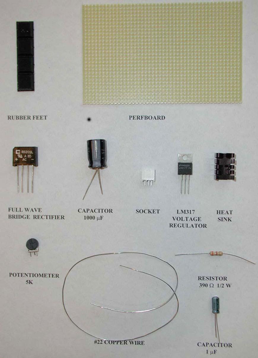
36 Figure 20: Lamp and socket One lead to each filament is connected to the brass shell and the other lead is connected to one of the two terminals (soldered bumps) on the base of the lamp. Plug the lamp into the socket provided in your Red Box. There are two black leads from the socket. In order to connect one of the filaments to the LVPS, use your clip lead to connect one of the black wires from the socket to one output of the LVPS. Use a second clip lead to connect the other output of the LVPS to anywhere on the socket. (This connects the LVPS to the brass shell of the lamp.) Identify the 8W filament (cold resistance about 2Ω ), either with your MMM on the RX1 range or by lighting it with the LVPS---it's the upper filament in the lamp. Parts List for LVPS LVPS 1 perfboard 4 rubber feet 1 full wave bridge rectifier 1 electrolytic capacitor, 1000µF 1 socket for LM317T regulator 1 potentiometer, 5kΩ 1 electrolytic capacitor, 1µF 1 resistor, 390Ω 12W 1 ft wire, #22 bare solid 1 voltage regulator LM317T 1 heat sink for LM317 regulator LVPST 1 resistor, 2.4Ω 2W 1 lamp #1157 automotive RED BOX 1 socket for 1157 lamp 11
37 12
38 Testing the LVPS Each of you has built a power supply that converts ac (alternating current) power at 120V (volt), at a frequency of 60 Hz (hertz = cycles/sec) from the wall outlet into dc (direct current) power with a voltage range from 1.2V to about 17V. When the output voltage without load (lamp) is set between 1.2V and about 12 V, the output voltage will not change appreciably if a load is then placed across it. You will find that range when you place the 8W (watt) filament of an 1157 lamp across the output of the LVPS. See Building the LVPS: Trying out your LVPS. Measurements and Data You can set your pot at ten different settings from lowest to highest output by turning the top of the pot either clockwise or counterclockwise (depending on how you wired the legs). Set the pot so the no load output voltage is minimium, 2V, 4V, 6V, 8V, 10 V, 12 V, 14V, 16V, and maximum. Use the accompanying table to record the results of your measurements. For each setting you will: 1. Measure the output voltage (no-load voltage) of the LVPS when the lamp is not connected; 2. Measure the output voltage (load voltage) of the LVPS when the lamp is connected across the output of the LVPS. 3. Then connect the lamp and measure the load voltage across the terminals of the LVPS. Questions 1. What range of no-load output voltages remains unchanged after the lamp is connected across the LVPS output terminals? 2. Briefly describe how you distinguished between the 8W filament and the 27W filament? 3. What happens when you connect the outputs of the LVPS to the two black wires in the socket? Can you figure out the wiring diagram for the lamp? Graph Plot the output voltage of the LVPS without the lamp connected along the horizontal axis and the output voltage of the LVPS with the lamp connected along the vertical axis. 13
39 Data Table for LVPS Pot Setting V LVPS (no load) [volts] minimum maximum V LVPS (load) [volts] 14
40 Voltage, Current and Resistance Electric Charge There are two types of observed electric charge, positive and negative. Positive and negative are arbitrary names derived from Ben Franklin s experiments. He rubbed a glass rod with silk and called the charges on the glass rod positive. He rubbed sealing wax with fur and called the charge on the sealing wax negative. Like charges repel and opposite charges attract each other. The unit of charge, Q, is called the coulomb [C ]. Charge of ordinary objects is quantized in integral multiples Q = + Ne or Q = Ne where e = C, and N is some positive integer. The electron carries one unit of negative charge, q electron = e, and the proton carries one unit of positive charge, q proto n = +e. Voltage Sources Batteries, generators, power supplies are devices that convert some other form of energy into electrical energy. When the terminals of a battery are connected to a wire, forces act on charges, and produce a flow of charge in the wire, an electric current. Here the electrical energy comes from chemical reactions inside the battery. There are many sources of electromotive force: solar cells, generators, and alternators are a few examples. Voltage Difference The voltage difference V V B V A between points A and B is defined to be the negative of the work done W per charge, q, in moving the charge, q, from any point A to any point B W V =. q Voltage difference is also called electric potential difference. The unit of voltage difference is the volt [V ]. [V ]= [volt ]= [ joule / coulomb] = [J / C]. The work done W in the definition of the voltage difference is the work done by the electric force B r r W = F dr A 1
41 Work-Energy A positive charge free to move will go from a higher potential to a lower potential. Notice that V is negative and q > 0, hence the work done by the electromotive force is positive, ( W = q V > 0 ). This positive work can be converted to mechanical energy in the form of increased kinetic energy, ( W = K ), or converted to heat, ( W = Q heat ). A negative charge free to move will go from a lower potential to a higher potential. Current Electric currents are flows of electric charge. The electric current through a wire is defined to be the total net charge flowing across any cross-sectional area of the wire per second. The unit of current is the amp [ A] with 1 amp = 1 coulomb/sec. Common currents range from mega-amperes in lightning to nanoamperes in your nerves. There are two different systems of units, the SI or Système International d Unités, and the CGS (centimeter, grams, sec). In CGS units, charge is a fundamental quantity. The unit for charge is the electrostatic unit [esu ]. In the SI system, current is the fundamental quantity, and electric charge is a derived unit. This means that one coulomb is defined as follows. If one amp of current is flowing through a wire, then the total charge that moves across any cross-section of the wire in one second is defined to be one coulomb of charge. The idea that current, I, is the rate of change of charge, Q, in time can be described mathematically by the relation I = dq dt. Since flow has a direction, we have implicitly introduced a convention that the direction of current corresponds to the direction positive charges are flowing. Inside wires the flowing charges are negatively charged electrons. So the electrons are flowing opposite to the direction of positive current. There are many kinds of electric current: direct or alternating, high or low frequency, steady or transient, constant, slowly varying, pulsating or fluctuating. Electric currents flow in conductors: solids (metals, semiconductors), liquids (electrolytes) and ionized gases. Electric currents don t flow (much) in non-conductors or insulators. Power Supplies The rate of doing work is called power. A voltage source V that produces a current I has a power output P = VI. Voltage sources are commonly referred to as power supplies. The unit of power is the watt, [W ]; [W ]= [watt] = [volt][amp]= [V ][A]. 2
42 Since power is the rate of change of energy with time, the units of watts are also Electric Circuits [W ]= [watt] = [ joule / sec] = [J / s]. Electrical circuits connect power supplies to `loads such as resistors, motors, heaters, or lamps. The connection between the supply and the load is made with insulating wires that are often called `leads and soldering, or with many kinds of connectors and terminals. Energy is delivered from the source to the user on demand at the flick of a switch. Sometimes many circuit elements are connected to the same lead, which is the called a `common lead for those elements. Various parts of circuits, called circuit elements, can be in series or in parallel, or seriesparallel. Elements are in parallel when they are connected `across the same voltage difference (see Figure 1). Figure 1: parallel elements Generally, loads are connected in parallel across the power supply. When the elements are connected one after another, so that the current passes through each element without any branches, the elements are in series (see Figure 2). Figure 2: series elements There are pictorial diagrams that show wires and components roughly as they appear, and schematic diagrams that use conventional symbols, somewhat analogous to road maps. 3
43 Often there is a switch in series; when the switch is open the load is disconnected; when the switch is closed, the load is connected. One can have closed circuits, through which current flows, or open circuits in which there are no currents. Sometimes, usually by accident, wires may touch, causing a short circuit. Most of the current flows through the short, while very little will flow through the load. This may burn out a piece of electrical equipment like a transformer. To prevent damage, a fuse or circuit breaker is put in series. When there is a short the fuse blows, or the breaker opens. In electrical circuits, a point (or some common lead) is chosen as the ground. This point is assigned an arbitrary voltage, usually zero, and the voltage V at any point in the circuit is defined as the voltage difference between that point and ground. Resistance and Ohm s Law When a voltage difference, V, is applied to a circuit element, a current flows through it. The amount of the current is a function of the voltage. The current-versus-voltage relationship ( I V curve) is an empirical property of the element. Three examples are shown in Figure 3. Figure 3a shows a linear relation when the element is carbon composition resistor, Figure 3b shows a more complicated non-linear relation for the 8W filament of the 1157 lamp, and Figure 3c shows the unsymmetrical non-linear relation for a diode. 3a: Carbon composition resistor 3b: Lamp 3c: Diode Figure 3: I V curves for various elements When the I V curve is linear, the resistance R is defined to be the slope of the curve. V R =. I This is known as Ohm s Law, commonly stated as follows: the voltage drop, V > 0, across a resistor is V = I R. The unit of resistance is the ohm [Ω], with [Ω] = [ Ω] [V ] since (1 ohm) = 4
44 (1 volt)/(1 amp). The resistance of a resistor may not be constant but may depend on a number of variables such as temperature or applied voltage. Power Dissipated by a Resistor The power dissipated by a resistor as heat, called Joule heating, is given by P = VI = I 2 R = V 2. R Resistors are rated by the power they can safely dissipate. Current Conservation A node is a point in a circuit where three or more elements are soldered together. At any point where there is a junction between various current carrying branches, the sum of the currents into the node must equal the sum of the currents out of the node. Loop Rule I in = I out The sum of the voltage drops, V i, across any circuit elements that form a closed circuit is zero. This is just the statement that the electric field does zero work per charge in moving a charge around a closed path. i= N V i = 0. i= 1 Example 1 Consider the following closed circuit consisting of one branch that has an electromotive (voltage) source ε, a switch S, and two resistors, R 1 and R 2, with R 1 = 4R 2. When the switch, S is closed, current will flow in the circuit. In this circuit there is only one branch, so there is only one current that flows in this circuit. This current, flowing through the wire, also flows inside the voltage source. Figure 4a: One loop circuit, open switch Figure 4b): One loop circuit, closed switch 5
45 A graph of the voltage vs. position along the loop (see Figure 5) shows that the highest voltage is immediately after the battery. The voltage drops as each resistor is crossed. Note that the voltage is essentially constant along the wires. This is because the wires have a negligibly small resistance compared to the resistors. Figure 5a) Voltage changes around a closed loop Figure 5b: Voltage Difference between points on a closed circuit and common Resistors in Series The two resistors, R 1 and R 2, in Figure 6 are connected in series to a voltage source, V S. By current conservation, the same current, I, is flowing through each resistor. 6
46 6a: Resistors in series 6b: Equivalent resistance The total voltage drop across both elements is the sum of the voltage drops across the individual resistors V = IR 1 + IR 2. Two resistors in series can be replaced by one equivalent resistor, R eq (Figure 6b). The voltage drop across the equivalent resistor is given by V = IR. eq Therefore when any number of resistors are placed in series, the equivalent resistance is just the sum of the original resistances. R = R 1 + R eq Notice that if one resistor, R 1, is much bigger than the other resistor, R 2, then the equivalent resistor, R eq is approximately equal to the larger resistor, R 1. Resistors in parallel Consider two resistors, R 1 and R 2, that are connected in parallel across a voltage source V (Figure 7a). Figure 7a: resistors in parallel 7b: equivalent resistance By current conservation, the current, I, that flows through the voltage source must divide into a current, I 1, that flows through resistor, R 1, and a current, I 2, that flows through resistor, R 2. Each 7
47 resistor individually satisfies Ohm s law, V = I 1 R 1 and V = I 2 R 2. Therefore current conservation becomes V V 1 1 I = I 1 + I 2 = + = V( + ). R1 R 2 R 1 R 2 The two resistors in parallel can be replaced by one equivalent resistor, R eq, with the identical voltage drop, V (Figure 7b), and the current, I, satisfies V I = R. eq Comparing these results, the equivalent resistance for two resistors that are connected in parallel is given by R eq = R1 + R2. This result easily generalizes to any number of resistors that are connected in parallel = R eq R 1 R 2 R 3 When one resistor, R 1, is much bigger than the other resistor, R 2, then the equivalent resistor, R eq, is approximately equal to the smaller resistor, R 2, because R 1 R R 2 eq = R2. R 1 + R 2 This means that almost all of the current that enters the node point will pass through the branch containing the smaller resistance. So when a short develops across a circuit, all of the current passes through this path of nearly zero resistance. Voltage Divider Consider a voltage source, V in, that is connected in series to two resistors, R 1 and R 2 8
48 Figure 8: voltage divider The voltage difference, V out, across resistor, R 2, will be less than V in. This circuit is called a voltage divider. From the loop rule, So the current in the circuit is given by V in IR 1 IR 2 = 0. V in I =. R 1 + R 2 Thus the voltage difference, V out, across resistor, R 2, is given by V in V out = IR 2 = R 1 + R 2 R 2. Note that the ratio of the voltages characterizes the voltage divider and is determined by the resistors V out = R 2. V in R 1 + R 2 9
49 Internal Resistance of a Voltage Source Voltage sources have an intrinsic internal resistance (that may vary with current, temperature, past history, etc.). This means that when a load is place across the power supply, the voltage across the terminals, V load, will drop. When an external load is connected across the power supply, the circuit diagram looks like (see Figure 9): Figure 9: Internal resistance of a voltage source The terminal to terminal voltage, V load, across the power supply when the load is connected is given by V load = V no load IR int The external circuit has a voltage drop given by Ohm s law: V load = IR load Therefore the current in the circuit is V load I =. R load The internal resistance can now be calculated The loop rule for the circuit law yields Rint V no load V = load. I V no load IR int IR load = 0, so the current in the circuit can also be expressed in terms of the no-load voltage and the load resistance 10
50 V no load I =. Rload + R int The power lost to the internal resistance is given by V no load Pjoule = I 2 R int = ( ) 2 R Rload + R int int When the terminals of a power supply are shorted by a wire with negligible resistance, there is an upper limit to the short-circuit current Voltage-Current Measurements V no load I =. sc R int Any instrument that measure voltage or current will disturb the circuit under observation. Some devices, ammeters, will indicate the flow of current by a meter movement. There will be some voltage drop due to the resistance of the flow of current through the ammeter. An ideal ammeter has zero resistance, but in the case of your MMM, the resistance is 1Ω on the 250mDCA range. The drop of 0.25V may or may not be negligible, but you can correct for it. Again, knowing the meter resistance allows one to correct for its effect on the circuit. An ammeter can be converted to a voltmeter by putting a resistor, R, in series with the coil movement. The voltage across some circuit element can be determined by connecting the coil movement and resistor in parallel with the circuit element. This causes a small amount of current to flow through the coil movement. The voltage across the element can now be determined by measuring I and computing the voltage from V = IR which is read on a calibrated scale. The larger the resistance, R, the smaller the amount of current is diverted through the coil. Thus an ideal voltmeter would have an infinite resistance. 11
51 0 Black 1 Brown 2 Red 3 Orange 4 Yellow 5 Green 6 Blue 7 Violet 8 Gray 9 White 1 Gold 2 Silver Resistor Value Chart The colored bands on a composition resistor specify numbers according to the chart above (2-7 follow the rainbow spectrum). Starting from the end to which the bands are closest, the first two numbers specify the significant figures of the value of the resistor and the third number represents a power of ten by which the first two numbers are to be multiplied (gold is 10 1 ). The fourth specifies the tolerance or accuracy, gold being 5% and silver 10%. Example: 43Ω 5% tolerance is represented by yellow, orange, black, gold. 12
52 Introduction Experiment VI Voltage, Current and Resistance Our world is filled with devices that contain electrical circuits in which various voltage sources cause currents to flow. We use radios, telephones, computers, flashlights, irons, heaters, stoves, motors the list is long. Each of these contain circuits which take electrical energy from some power supply and turn it into other forms: the light of a lamp, the heat of a stove, stereo sound or mechanical work. In general, electrical currents generate heat and magnetic fields, and produce chemical effects. Any of these phenomena can be used to measure current. One of the simplest ways is to let the current flow through a coil of wire that is in a magnetic field and to measure the resulting torque on the coil by observing the deflection of a torsion spring. This is how your multimeter works, which we call a magnetic multimeter (MMM), in contrast to the standard term `analog. Look at the meter itself. You can see the copper colored coil and one of the two spiral torsion springs (the other is at the back; they also lead current in and out of the moving coil). The MMM is a current meter with a range selector switch and appropriate resistors and other parts that can measure voltage and resistances. One of the earliest and most widely used electrical devices is the incandescent lamp, of which there are hundreds of different kinds. They all work because current flowing through a tungsten filament in a glass bulb heats that filament to incandescence visibly hot, so that light is emitted, along with heat. In this experiment you will use meters, power supplies, resistors and lamps in various circuits. You will make measurements to get some intuition and knowledge of circuit behavior. Equipment You will need your LVPS; two multimeters; three 43Ω, (power rating 1 2W ) resistors; one 2.4Ω, 2W resistor; one length of #16 bare resistance wire (1.02Ω per meter); one #47 miniature incandescent lamp, nominal rating 0.15 A at 6.3V (called pilot, panel or indicator lamp); and one #1157 auto tail and stop lamp (tail lamp filament with a nominal rating of 8W at 12.6V ; stop lamp filament with a nominal rating of 27W at 12.6V ). Look closely at your lamps and notice the filament, conducting leads and glass insulator. Throughout this experiment you will need clip leads. 1

53 Measurements Arrange the experimental apparatus as directed and record your measurements on the separate RESULTS sheet in the problem set. You may wish to add brief comments, as appropriate Resistors and Lamps: Measure the resistance of each of the three 43Ω resistors, R 1, R 2, and R 3. Solder together resistors R 2 and R 3 in parallel. Then solder resistor R 1 in series with the other two as shown in Figure 1. Measure the resistances between the points A and B, B and C, and A and C in Figure 2. Measure the cold resistances (not connected to a power supply) of the #47 lamp and the two #1157 lamp filaments. Figure 1: Three 43 Ω Resistors, one in series with two in parallel Figure 2: Circuit Diagram: Three 43Ω Resistors, one in series with two in parallel 2a---Voltage Divider: Connect the arrangement of the three resistors in Figure 1 to your LVPS with the output set at 5 volts. Measure the voltage differences between the points A and B, B and C, and A and C in Figure 2. Calculate the current through each resistor using Ohm s Law and calculate the power dissipated in each resistor. 2b---Voltage and Current: Connect the arrangement of the three resistors in Figure 1 to your LVPS with the output set at 5 volts. Use a clip lead to short the two resistors ( R 2 and R 3 ) that are connected in parallel, (connect B to C in Figure 2). Measure the voltage between A and B. Calculate the current and power dissipated through the remaining resistor R 1. Observe the warming of resistor R 1 by feeling it with your fingers. 2
54 2c---Voltage and Current: Connect the arrangement of the three resistors in Figure 1 to your LVPS with the output set at 5 volts. Now use the clip lead to short resistor R 1 by connecting A to B. Measure the voltage between B and C. Calculate the current and power dissipated through the resistors R 2 and R 3. Observe the warming of the two resistors in parallel by feeling them with your fingers. 3a---Voltage-Current (V-I) Characteristics: Set your LVPS to its lowest output voltage (around 1.5V ). Connect one MMM on the 250mDCA range in series with one 43Ω resistor across the LVPS output (Figure 3a). Be careful of shorts that might damage the MMM. (If your MMM suddenly stops working you probably blew the fuse. Open the back and replace the fuse with one of your spare fuses.) Connect the other MMM on the 5DCV range across the resistor (Figure 3a). Adjust the voltage output (turn the pot) of the LVPS so that your MMM on the 5DCV range across the resistor reads 1.5V, 2V, 3V, 4V, and 5V. Record the values of the current for each voltage setting. Figure 3a: Voltage-Current (V-I) Characteristics for the 43 Ω resistor 3b---#47 Lamp: Set your LVPS to its lowest output voltage and repeat the V I measurements with the #47 lamp instead of the 43Ω resistor. You can use one of the sockets provided to connect the #47 lamp. Use your clip leads to connect to the socket tabs. Figure 3b: Voltage-Current (V-I) Characteristics for #47 lamp 3c---#1157 Lamp: Set your LVPS to its lowest output voltage. Identify the 8W filament lead (it s the one with the higher resistance---use your ohmmeter to determine this; sometimes the contact is not good initially when the lamp is plugged into the socket. Try cleaning the contacts with a screwdriver blade). Use a clip lead to connect the positive terminal of the LVPS to one 3
.")
55 end of the foot long piece of resistance wire that can be found in the top tray your Red Box. Use a second clip lead to connect the other end of the resistance wire to the shell of the lamp socket. Connect the 8W filament lead to the minus terminal of the LVPS (see Figure 3c). Figure 3c: Voltage-Current (V-I) Characteristics for #1157 lamp Connect one MMM on the 25DCV range (not shown in Figure 3c) across the #1157 lamp. Connect the other MMM set on the 50µ (250mV)DCA range across a measured length of the resistance wire (0.2 m is a good choice). The wire has resistance 1.02Ω per meter so a length of 0.2 m between the MMM probes corresponds to a resistance of 0.2Ω. When a current of 0.5 A flows through the resistance wire then there will be a voltage drop V = IR = ( 0.5A)( 0.2Ω ) = 100 mv. This will give almost a half scale reading on the 50µ(250mV)DCA setting. (On the 50µ (250mV)DCA range the MMM will measure between 0V and 250 mv on the black DC scale.) Adjust the voltage across the #1157 lamp to 2V, 4V, 6V, 8V, 10V. Record the values of the voltage across the resistance wire for each voltage setting. Calculate the current through the resistance wire for each voltage setting. Note the LM315T regulator may overheat and shut down; if this happens simply disconnect the lamp for a minute to let things cool down. 4a--- Some LVPS Properties A full characterization of the LVPS is a lot of work, but a few measurements will show some of its behavior. Connect a MMM on the 5DCV range across the output of the LVPS. Set your LVPS to 1.5V (no load voltage). Use clip leads to connect the 2.4 Ω, 2W resistor (from LVPST kit) across the LVPS output just long enough to see if the MMM reading changes (Figure 4a). Record the output voltage (load voltage) of the LVPS with the 2.4Ω resistor load attached. Disconnect the resistor load and adjust the LVPS (no load voltage) for 2V, 3V, 4V, and 5V.. Record the output voltages with the 2.4Ω resistor load for each setting of the LVPS. Then switch the MMM range to 25DCV, for setting of the LVPS of 10 V and 15V. Record the output voltages with the 2.4Ω resistor load for each setting of the LVPS. 4
56 Figure 4a: Measuring LVPS Properties Notice that for low voltages there isn t much change when the load is applied --- estimate the readings as best as you can. At any voltage much over 2V you will be overloading the resistor, so that s why you shouldn t leave it connected for long. 4b--- LVPS Short Circuit Current: Set your LVPS to its lowest output voltage. Connect the two ends of the resistance wire across the LVPS output. Connect a MMM on the 50µ(250mV) DCA range across 100 mm of the resistance wire. This is pretty close to a short circuit so calculate the short circuit I SC by measuring the voltage across the 100 mm of resistance wire (resistance 0.1Ω ). Turn the adjusting pot on the LVPS to see if the I SC varies Charging a Capacitor: Carefully zero a MMM on the RX1K range by connecting the leads together and adjusting the red OHMS ADJUST dial. Set the range switch to `OFF. You will only be able to make this measurement once so please follow directions carefully. Connect the 1000µF capacitor with the red positive lead of the meter going to the negative lead of capacitor, and the black negative lead of the meter going to the positive lead of the capacitor. As soon as you turn the MMM range to RX1K start your clock. Measure the time at which the pointer reaches 4.5, 4, 3, 2, 1, and 0.5 on the black DC scale with 5 as maximum. Record your results. If you are unable to get data during the first run, on the next run the meter will only point between 1 and 3 on the black DC scale. You can still measure the time it takes the pointer to reach 2.5, 2, 1.5, 1 on the black DC scale. 5
57 Parts List You will be using parts from several different parts kits and the Red Box. LVPS Red Box 2 MMM 1 transformer 120V ac to 12V ac 1' 800 wire 1 lamp socket (#1157) 1 clip lead kit (CLK) LVPST Test Kit 1 resistor, 2.4Ω 2W 1 lamp #1157 automotive Experiment VI: Voltage and Current 3 lamps, #47 6.3V 0.15 A 3 lamp holders 3 resistors, 43Ω 12W 1 electrolytic capacitor, 1000µF 1 ft wire, #22 insulated stranded 6
58 Report Experiment VI: Voltage and Current Data and Analysis Arrange experimental apparatus as directed in the Experiment VI: Measurements p.13 and record results on the appropriate tables below Resistors and Lamps (all values in ohms) Resistance of three 43Ω resistors: R 1 =, R 2 =, and R 3 =. R AB =, R BC =, and R AC =. Resistance of Lamps: #47 =, #1157, 8W =, #1157, 27W =. 2.Voltage Measurements 2a---Voltage Divider Voltages (in volts): V AB =, V BC =, V AC =. Current (in amperes) through Resistors: I 1 =, I 2 =, I 3 =. Power (in watts) dissipated by Resistors: P 1 =, P 2 =, P 3 =. 2b---Voltage and Current Current (in amperes) through Resistor R 1 : I 1 =. Power (in watts) dissipated by Resistor R 1 : P 1 =, 2c---Voltage and Current Current (in amperes) through Resistors R 2 and R 3 : I 2 =, I 3 =. Power (in watts) dissipated by Resistors R 2 and R 3 : P 2 =, P 3 =. 3---Voltage-Current (V-I) Characteristics 3a) 3a) 3b) 3b) 3c) 3c) 3c) 43Ω 43Ω #47 #47 #1157 8W #1157 8W #1157 8W Voltage [ V ] Current Voltage Current Voltage [ V ] Res. Wire Current across 43Ω [ A] [ V ] across [ A] across #1157 [ mv ] [ A] #47 Length of resistance wire (in mm ) =, Resistance of wire ( in Ω ) =. 7
59 4--- Some LVPS Properties No Load Voltage V [ V ] no load Voltage with Load V load [V ] V - V load [ V ] no load 4b--- LVPS Short Circuit Current (in amperes) ISC = Charging a Capacitor MMM Time [ s ] reading
60 Problem 1: Internal resistance of the LVPS When the output voltage of the LVPS is between 1.5V and 12.0V, the output voltage does not noticeably change when a reasonable load is connected. This means that the internal resistance is very small, in the range between 0.01Ω and 0.001Ω. However when the output voltage of the LVPS is above 12.0V, the internal resistance increases substantially. a) How can you determine the internal resistance as a function of load? b) From your data from the LVPS with the #1157 lamp as the load, determine the internal resistance as a function of load? Problem 2: Calculating the internal resistance of an AA cell. An AA cell when there is no load connected to it, has a terminal to terminal voltage of 1.50V. When a 2.4Ω resistor is connected in series to an AA cell, the terminal voltage drops to 1.33V. What is the current in the circuit? What is the internal resistance of the AA cell? What is the short-circuit current if the terminals are connected by a wire with negligible resistance assuming that the internal resistance is constant? What power is lost to the internal resistance? 9
61 Introduction Building the HVPS High Voltage Power Supply Voltages higher than the LVPS provides kilovolts are needed in later experiments to get strong electric fields and to generate microwaves. The high-voltage power supply makes such experiments possible. You will have voltages from 100V to 1000V available to you, at a safe current of less than a milliampere. The HVPS is built on the empty space of the LVPS board and is powered by it. Some experiments in this course will need both the HVPS and another device, an amplifier, which will be built on the board of a second LVPS. You and your partner will have the necessary pair of LVPS s between you; if you are working alone, you will eventually need two LVPS s. Background To get adjustable high voltage, we will convert the adjustable dc from the LVPS into adjustable ac at a frequency of about, by means of an LC oscillator. Then, a step-up transformer will be used to get high voltage ac, which can be turned into dc with a half-wave voltage-doubler rectifier. Here is the block diagram: Figure 1: HVPS block diagram Figure 2: HVPS circuit diagram 1
62 The oscillator is powered by the 2N3055 transistor. The main feature of a transistor is that a small current from base to emitter results in a large current from collector to emitter (larger by a factor of order 100). Then the emitter current flows through an six turn primary winding on a transformer made by using the windings of a 5 millihenry inductor as the secondary, as shown below. The transformer is a device that converts an ac voltage across the primary coil winding into a different ac voltage across the secondary coil winding. This is accomplished by using two closely spaced coils of different number of turns, one is called the primary, and the other, the secondary. The primary coil has a number of turns denoted by N P, and the secondary coil has N s number of turns. Then the voltage across the primary, V P, is related to the voltage across the secondary, V S, according to V P V = S. N P N S The secondary has about 300 turns, so the secondary voltage is about 50 times the primary voltage. Figure 3: LC oscillator The secondary winding of the transformer is part of a parallel LC circuit with a resonant frequency f = 1 1 2π LC The inductance is 5mH and the equivalent capacitance is 91 pf, so the resonant frequency is f = 1 2π 1 LC = 1 2π 1 = Hz. ( H )( F ) 2
63 Figure 4: capacitor voltage divider The two capacitors shown above make a voltage divider, such that 1/11 of the total voltage across the coil appears across the 1000 pf (.001 microfarad) capacitor. This voltage is fed back to the base of the 2N3055. If the transformer windings are properly connected, an increasing current through the transistor will produce an emf in the secondary of the resonant circuit which, when part of it is fed back to the base of the transistor, has the correct polarity to cause yet more current to flow in the 2N3055. This is positive feedback, rather than the negative feedback utilized in the LVPS regulator. The positive feedback tries to make the transistor current go to infinity, which, of course, is not possible. The voltage across the primary coil does increase to almost the positive power supply voltage, at which point it must stop increasing, and the voltage induced in the transformer secondary goes through zero and changes sign. Then the positive feedback makes the current through the transistor plunge in the opposite direction to zero. Thus, an alternating voltage almost equal to the LVPS voltage is produced at the primary, at the resonant frequency of the LC circuit of which the transformer is a part. This ac is stepped up to 1000V or more, peak-to-peak (maximum to minimum), by the transformer action. The high voltage ac is rectified so as to produce an output dc voltage approximately equal to its peak-to-peak voltage, by using two high voltage diodes in a voltage doubler circuit: Figure 5: voltage doubler 3
64 Here is how is how the voltage doubler works: if the sine wave voltage across the resonant circuit has a peak-to-peak value 2V 0, then an alternating voltage of amplitude V 0 appears across the circuit composed of C 1 and D 1. Thus C 1 and D 1 act as a half-wave rectifier, which charges C 1 to V 0. As a result the sine wave voltage at point A causes the voltage at A to oscillate from 0 to 2V 0. The second diode, acting as a half-wave rectifier, will then charge to a voltage approximately equal to 2V 0. Hence the name doubler. Following the voltage doubler, there is a filter capacitor, C 2, and then each output lead is in series with a one megohm resistor. These are to isolate the supply from the long leads you may connect to it, and to reduce the intensity of the shock you can get by putting yourself across the output. The supply is safe, because the stored charge in the small filter capacitance is too small to be dangerous, and the steady output the supply can deliver is also too small to hurt you. However, if you touch it lightly you can feel the burn of the resulting spark. HVPS Parts LVPS, already built resistor, 8.2 kω 12W 2N3055T transistor, TO-220 type TO-220 white transistor socket clip on heat sink 2-1N5062 diodes, (max 800V peak inverse voltage, 750 ma max forward current) ferrite core inductor (5mH ), 3 segment 1 ft - #26 insulated solid wire 1 ft - #22 bare solid wire 1 ft - #22 red insulated solid wire 2-1 MΩ resistors, 1 2W ceramic disc capacitors: 100 pf, 1kV, [1 pf = 1 picofarad = F.] 1000 pf, 500V pf, 1kV 4

65 Recognizing the Parts Figure 6: Top view of HVPS Transistor: The transistor package looks like the regulator of the LVPS, and since it also produces heat that must be led away, you should mount a heat sink on it. The transistor is an amplifier of current, and in conjunction with the transformer produces ac at a frequency of about 240 khz. Figure 7: 2N3055T Transistor Inductor: Your inductor consists of three connected coils wound on a ferrite core (a magnetic sintered powder); the coils are about 45 feet in length, something under 500 turns of thin insulated wire. You will change the inductor into a step-up transformer converting low alternating voltage at relatively high current to high voltage at low current. (Your wall transformer, converting 120V ac to 12V ac, is a step-down transformer.) Figure 8: Inductor 5


66 Capacitors: The differences in shape and rating between these capacitors and the ones in the LVPS strongly suggest that they are made of different materials. That is true: also, this type of capacitor is not polarized as to current direction: it doesn t matter which way around you place it. The physical size of capacitors is determined by their voltage rating capacitance and the materials used in their construction. Figure 9: Ceramic Disk Capacitors To tell which capacitor is which use the decoding system for disc capacitors. Numbers on the discs that don t end with a zero in the units place, for example numbers like 102, have a code meaning: the 2 means put 2 zeros here. So, 102 = 1000, 101 = 100, and 471 = 470. In addition, numbers that are not decimal fractions should be read as picofarads (10-12 F), whereas decimal fractions, like.001 in the figure, mean microfarads (10-6 F). Thus.001 =.001 x 10-6 farads or 1000 picofarads. The capital letters following these numbers indicate tolerances. Some of the other coding tells the factory name, the country of origin or the manufacturer. Diodes: The diodes pass current from the + anode, to the - cathode, the black end in the case of the 1N5062. (Placing the diode in the wrong direction can happen; so note carefully the black end). Figure 10: 1N5062 Diode 6

, where the wire enters the coil at the inner core.")
67 Construction Notes Making the Transformer To make the inductor into a transformer, you will need to wind six turns of the insulated #26 solid wire onto the core of the inductor to act as the primary coil. First cut the wire to inches and strip off the insulation from the two ends to expose the bare wire. Notice that the windings already on the inductor are in three parts; wind three of your turns in each of the two gaps between. Wind in the same direction as the winding already there. Here s how; find the starting end of the inductor winding (see Figure 11), where the wire enters the coil at the inner core. Hold the inductor by that end and wind in a counterclockwise direction, three turns in the first gap and three in the second. The wire already on the inductor is thin, fragile and exposed. Breaking these wires is a common source of trouble with HVPS construction. Don t wrap your turns so tightly as to break the wires already there. Figure 11: Winding the Transformer You have now made a transformer. Check for electrical continuity in both coils to make sure no wire got broken. If it is unbroken, you will see about ohms (depending on the make of the inductor) across the inductor s coil. The 6-turns you added, which become the primary of the transformer, have a small resistance (too small to measure). There should be no electrical connection between the two coils. You should certainly check for this if you run into any troubles. Perfboard Diagram for the Top of the HVPS The figure below shows the placement of HVPS parts on the top of the perfboard. Start with one of the boards on which you have already built a low-voltage power supply (LVPS). Follow the parts layout shown in the pictures and in the templates shown below. 7


68 Figure 12: Parts lay out for the HVPS Figure 13: Diode and inductor wiring A common mistake is to wire the diodes the wrong way. In Figure 13 the wiring for the diodes is shown. Notice that one end of the diode is dark. Make sure that these ends point in the correct direction. Another common mistake is to wrap the primary in the wrong direction with respect to the secondary wrappings of the ferrite core inductor. If the HVPS does not work correctly, you may want to rewrap the primary wire. You will need to unsolder the primary. Another way to correct this problem is to unsolder the wires that emerge from either end of the ferrite core inductor. Then flip the inductor and re-solder the ends so that it will now connect the other way. For this reason the ends of the secondary are soldered above the board. Once you are sure you have the wires the correct way you may want to solder the ends from the inductor underneath the board for more stability. 8

69 One leg of the 1000 pf capacitor first passes underneath the board then returns to the top side of the board where it soldered to the wire emerging from the end of the inductor. The other end of the inductor is soldered to the 470 pf capacitor. Perfboard Diagram for the Bottom of the HVPS The diagram below shows the wiring of HVPS parts on the bottom of the perfboard. The solid lines point to where the indicated components are soldered or go through the board. The positive and negative LVPS lines are marked. Figure 14: Bottom View When you assemble your HVPS make sure that connections are convenient and that shorts are not likely to occur. Be sure to get the diodes the right way around, and remember to connect to the outputs of the LVPS. The HVPS ends up with two 1-megohm resistors to limit the current to completely safe values, less than 1 ma (milliampere). Testing the HVPS Here are some procedures to follow for your circuit tests. Set your multimeter to the l K range and connect to the output leads. (You must use the appropriate input to the meter, labeled +DC1000 V.) 9

70 Figure 15: Test lead inputs to multimeter for 1 K range Insert the 2N3055T transistor into the clip on heat sink. Insert the transistor into the transistor socket. The writing on the transistor should face the opposite direction from the inductor. Insert your LM317 regulator into the LVPS and also make sure it is facing the correct direction (towards the rectifier). Plug in the wall transformer. You should be able to adjust the HVPS output voltage to anywhere from 100V to over 1000V by turning the pot of the LVPS. You can expect several components to get hot after a while. The transistor will probably be the most noticeable one. Because of the low power involved (about 1 watt), it is safe in this case to short the output with a clip lead. You ll probably see small sparks when you do so. You can also put your fingers across the output (not usually a good practice!) because the current is limited to less than 1mA. If you do, you may feel a slight tingling sensation if you grasp firmly, or the burn of the spark if you hold it loosely. Troubles? If you get no output voltage: 1) Did you plug in your transistors? 2) Do you have a low-voltage input? Connect the multimeter on the 25V range to the LVPS output terminals; set the LVPS for 10V or so. 3) Feel the 3055 transistor. It should warm up after a minute. (A film of water placed on it would evaporate in a few seconds -- but wouldn t sizzle!) a) If the transistor s not hot, measure the voltage between each of its terminals and the minus terminal of the LVPS. The base could read 0.5V positive and the emitter will read zero if the circuit is not oscillating; if it is oscillating you may get hard-tointerpret readings even with only one meter lead connected. The collector reading should match the output of the LVPS. Other readings might suggest wrong wiring or a bad transistor. 10
71 b) If the 3055 is hot but the circuit is not oscillating, reverse the primary leads of the transformer you wound. This makes the feedback positive as needed for oscillation. 4) If you still see no high-voltage output, check the capacitative dividers for correct placement. (The 100 pf capacitor may be physically larger than the 1000 pf.) Could they be defective? Check the capacitors themselves: on the ohmmeter they should show infinite resistance. 5) If the capacitors are OK, see if there is 240 khz on the secondary of the transformer. Apply maximum voltage from the LVPS to the HVPS and touch the hot top-side of the transformer secondary with a regular wooden or plastic lead pencil. You should see a small spark. If not, reverse the transformer leads one more time and try again. Disconnect the first 470 pf capacitor. Now look again for 240 khz. If you don t see it, reverse the transformer leads one last time! If you still get no ac reading, the problem is too subtle for these techniques. (See an expert in the lab help sessions.) 6) If you do have ac, check the 470 pf for shorts. Also use the ohmmeter to check the diodes. We tested several diodes and got these readings on the various ohmmeter ranges with the red lead (+) connected to the cathode: Rx1: 20Ω, Rx10: 180Ω, Rx1k: 9 kω. With the meter leads reversed we got on all ranges. Now it has to work, unless it is a really tricky problem. Rebuilding with greater care to follow the drawing of the perfboard often clears matters up. Sometimes the only recourse is a persevering expert. Try this Bring a transistor radio close to your HVPS. Turn the radio on and place it inches from the coil. On almost any AM dial setting the radio will reproduce a strong buzz that will disappear if you unplug the power supply, or even turn the pot down. If you make a spark at the output, you should hear it broadcast sharply. 11
72 Testing the HVPS Measurements: We will measure the voltage output of the HVPS with no-load and with the 1 MΩ resistors as loads. Adjust the pot on your LVPS so that the output voltage of the LVPS is between 1.5V and 12V. Use one of your multimeters to monitor the output voltage of the LVPS throughout the following measurements. Set the other multimeter to the l K range and connect the leads not at the output of the HVPS but just before the 1 MΩ resistors. (Use the appropriate input to the meter, labeled +DC1000 V.) 1) Determine the range of output voltages for the HVPS. Now make five measurements of your HVPS between 100V to 1000V with three loads, MMM only, the MMM and the two 1 MΩ resistors, and the MMM and one 1MΩ resistor. For each setting of the pot: 2) For each setting of the pot, measure the output voltage of the HVPS with your MMM (note that the MMM is the only load). 3) Use a clip lead to connect the ends of the two 1 MΩ resistors together so as to put them in series across the output of the HVPS. For each setting of the pot, measure the new output load voltage of the HVPS. 4) Use a clip lead to put only one of the 1 MΩ resistors as a load across the output of the HVPS. For each setting of the pot, measure the new output voltage of the HVPS. Record your results in the accompanying data table. 12
73 Data Table for HVPS Problem V LVPS V HVPS (no load) [V] V HVPS ( 2 MΩ load) [V] V HVPS (1 MΩ load) [V] Current HVPS ( 2 MΩ load) [I] Current HVPS (1 MΩ load) [I] 5) The multi-meter, on the 1K scale, acts like a resistor with resistance of 20,000Ω / VDC. This means that to find the resistance you multiple 20,000Ω / VDC by the full scale voltage reading which is 1000V. What is the resistance R MMM of your multi-meter on the 1K scale? 6) Draw circuit diagrams of your HVPS, the multi-meter and the loads. Is your multi-meter in parallel or in series with the load? 7) Is the multi-meter is in parallel or in series with the load equivalent resistance R eq? What is the equivalent resistance for loads of 2 MΩ and 1 MΩ loads? 8) Calculate the current output of your HVPS is given by V output I =. R eq 9) Calculate the current output of your HVPS for each setting of the LVPS pot for both the 2 MΩ load and 1 MΩ load. Record your results in the last two columns of the data table. 13
74 Experiment EF Electrostatic Force Introduction In this experiment you ll investigate aspects of the electrostatic force. This force has such varied roles as making currents flow in wires, holding atoms and molecules together, making clothes cling, glue stick, etc. The strength of the electrostatic force is proportional to the product of a charge (measured in coulombs) and the electric field (measured in volts/meter) produced by the other charges. You ll set up a horizontal parallel plate capacitor and find the voltage at which a piece of aluminum foil of known weight just lifts off the bottom plate. The electric force then just balances the force of gravity, r r F electric = F gravity. Besides a single thickness of foil, you will use folded foils equivalent to n thickness as well. The electric field between the plates is proportional to the surface charge density on the plates. When the electric field is measured in SI units, the constant of proportionality between the field and the surface charge density is determined by ε 0, the permittivity of free space. From the relations between measured or known electrical quantities, material properties and apparatus dimensions you can determine the constant ε 0. Theory You want to equate the gravitational and electric forces on the foil. The gravitational force is just the weight of the foil. The density ρ of the aluminum foil material is 2.7 grams/cc ( kg / m 3 ). The volume of the foil is then its area, A foil, times its thickness t. Therefore the magnitude of the gravitational force on the foil is F grav ity = m tot a l g = ρta foil g. Finding the electrical force is a bit subtler. Treat the closely spaced, metal portions of the washers as a parallel-plate capacitor. The electric force on the foil will be its charge times the electric field it feels. The subtlety lies in calculating that field: The total field in the capacitor is just V d where V is the applied voltage and d is the spacing between the plates. But only half that field is due to charges on the upper plate; and the other half is due to charges on the lower plate. Gauss's Law, states that the electric flux through a Gaussian surface is equal to the charge enclosed in a Gaussian surface divided by the constant ε 0. r r E da = qenclosed ε 0 Gaussian surface 1
 Figure 1: Gaussian surface for parallel discs The electric flux through the Gaussian surface is just the constant electric field inside the gap, E, times the area, a, of the end cap.")
75 Choose a cylindrical Gaussian surface whose upper end is inside the top plate and whose bottom end has area a and is within the gap. (See Figure 1.) Figure 1: Gaussian surface for parallel discs The electric flux through the Gaussian surface is just the constant electric field inside the gap, E, times the area, a, of the end cap. (Note the electric field is zero on the end cap that is outside the surface). The charge enclosed by the Gaussian surface is a times the charge density σ (charge/area) on the upper plate. So applying Gauss's Law yields that the total electric field in the gap is E = σ ε 0. Therefore the charge density, σ, can be found by equating the total field, E = V d, to the field found from Gauss's Law: V σ=ε. o d To find the electric force on the foil, assume that the charge density, σ, on the foil, is the same as that of the lower washer. Here comes the subtle point. By thinking about the electric field from the charge sheets on the inner surfaces of the plates (positive on top and negative on the bottom) you come to the conclusion that 1/2 the total field comes from the upper plate and half from the lower plate. Charges on the foil feel only horizontal forces from other charges on the bottom plate, so the vertical force on the foil is due to the electric field of just the top charge sheet. The magnitude is given by: V ε F electric = Q foil E top =σa o V 2 A foil foil = 2d 2 d 2 Equating the electric and gravitation forces yields, The area of the foil, A foil, cancels giving: ε o V 2 A foil 2 d 2 = ρta foil g. 2

76 V 2 2d 2 ρ g = t. ε 0 If you plot V 2 vs. t, you should get a straight line whose slope is the coefficient of t. You can calculate the free permittivity of space, ε 0, from your experimental value for the slope: Use the following values: 2ρ gd 2 ε =. 0 slope thickness of perf-board + tape, d = m ; thickness of Aluminum foil, t = m ; 3 density of Aluminum foil, ρ = Al kg / m ; acceleration due to gravity, g = 9. 8m / s 2. Apparatus First make a parallel plate capacitor from two large washers (2.5 inch diameter). The experiment depends on the smoothness and cleanliness of the washers and the cleanliness of the foil. You can t do much about the smoothness of the washers beyond choosing, by sight and touch, the best areas for where you put the foil (use a finger nail to feel the surface of the washer). Rub the washers vigorously with a paper towel to remove finger grease or other crud. Break the piece of perf-board into three equal sized pieces. Tape the 3 pieces of perf-board to one of the large washers at about 120 separations to form spacers that establish the gap between the washers. (Use black insulating tape.) Figure 2: perf-board used as spacers on washer The perf-board is 1.5mm thick, and the tape is 0.2 mm thick. Since you want the gap to be as uniform as possible, avoid burrs on the perf-board and smooth the tape down carefully. Press the second washer down on the spacers and check the gap measurement as best you can 3
. Connect the lower washer to the low voltage side of the HVPS.")
. You can use electrical tape to hold these connections firmly on the washers. Both MMM are set on the 1000DCV range.")
77 with your steel scale to be sure it s not grossly off. Tape two #30 wires to the outside of the washers, and place the first washer, the one with spacers, level on your desk. Use one of your MMM connected across the output of the HVPS to read the HVPS output (the right MMM in Figure 3). Connect the lower washer to the low voltage side of the HVPS. Connect the upper washer to the negative input of the second MMM. Connect the positive input of the second MMM to the high voltage side of the HVPS. This puts the second MMM in series with the gap (the left MMM in Figure 3). You can use electrical tape to hold these connections firmly on the washers. Both MMM are set on the 1000DCV range. Experiment Figure 3: Experiment EF connections Cut a square piece of foil, about 1cm 1cm. The foil should also be clean and flat, but it also needs to be given a rough texture to allow air to pass under it when it lifts off. Press it firmly on the 80 grit sandpaper found in the Red Box with a piece of tissue between foil and finger. Try to handle the foil with your fingers as little as possible to keep it clean. Tweezers work well for handling the foil. Alternately, you can tip it off the abrasive cloth onto a piece of paper and then slide it onto the washer. Transfer the foil to the bottom washer, and make sure that it s fairly flat. You can see that if the foil isn t flat, it either changes the gap or charge will flow out to the part nearest the upper washer so that larger forces will be exerted than if the foil were flat. Figure 4: Charge flows to edge of foil Figure 5: Charge flows to center of foil Put the top washer in place and turn up the HVPS all the way. The foil should lift off and bounce around. Turn down the voltage and repeat. When the foil lifts and shorts the gap, the 4

78 second MMM will register a voltage. Once the apparatus is working well, carefully and slowly raise the voltage and read the voltmeter when the foil lifts off. Read the voltage across the gap by the first MMM which is connected directly across the HVPS output. There are two other ways to determine when the foil lifts off the plate. Directly, by looking in the gap, seeing the foil lift, and having your partner read the voltmeter at that instant. Watch the MMM readings as you slowly increase the voltage. When the foil lifts and shorts the gap, the MMM reading will drop. Experiment EF Parts 1 strip perfboard 2 washers, 1in. plated steel 4 ft wire, #30 bare solid 1piece Al foil, 2in square in thick 1piece sand paper 80 grit Figure 6: Experiment EF parts 5
79 Experiment EF Data Analysis 1. Once the apparatus is working well, carefully and slowly raise the voltage and read the multimeter when the foil lifts off. Gentle tapping may help to get more reproducible results. Repeat 5 times. Take care that the foil isn t shorting the gap when you read the meter. (If you are having trouble, try different sizes of foil.) Prepare double and triple thickness foils (again about 1cm 1cm from pieces 2cm 1cm and 3cm 1cm, folded and squeezed flat, and repeat the above procedure. 2. Analysis: Average the voltages for a given foil thickness. You then have 3 numbers: the voltages required to lift 1, 2, and 3 thicknesses of foil. Use a table like this to enter your Experiment EF data Number Voltage Voltage Voltage Voltage Voltage Average of foils Trial 1 Trial 2 Trial 3 Trial 4 Trial 5 Voltage Plot the voltage squared V 2 vs. n, the number of thicknesses of foil. Is the origin a data point? (Zero voltage will lift zero folds of foil). Include your graph. 4. Your graph of the experimental values of V 2 vs. n should be a straight line with the slope being the factor in parentheses. Find the slope of the best-fit line. 5. Calculate the free permittivity of space ε 0, from your experimental value for the slope using the result that ρtg 2d 2 V 2 = n. ε 0 6
80 Problem 1: Electrostatic Force Experiment a) Using Gauss Law, find an expression for the electric field between two discs of radius R that are separated by a distance d. The discs have opposite charges that are equal in magnitude placed on them. You may neglect edge effects. Make a sketch of the electric filed lines when you include edge effects. b) Suppose a voltage difference V is applied across the two discs. Show that the charge on ε πr 2 o V the positive plate is given by the expression, Q = when you ignore edge effects. d c) Taking into consideration edge effects, the actual expression for the charge is given by ε πr 2 o V Q = f where f is a correction factor that depends on the ration of separation to d plate radius. For circular plates, the factor f depends on d / R as follows: d / R f Explain why the factor f is always greater than 1. Where is the extra charge? d) Find an expression for the capacitance of the circular discs neglecting edge effects. Now take into consideration the correction factor f. Is the actual capacitance larger or smaller? e) How would you expect your results in parts a) d) to change if you used two washers of inner radius r 1 and outer radius r 2 instead of two discs? 7
81 Problem 2: Internal Resistance of the HVPS In experiment EF, you connect the lower washer to the minus side of the HVPS, and the upper washer to the plus side. Let s approximate the internal resistance of the HVPS by 0.2MΩ and the two 1 MΩ gives a total internal resistance R T = 0 = 2.2 MΩ. Use one multimeter on the 1000V DC setting to read the HVPS output. Remember that this also acts as a 20MΩ resistor. Connect the second multimeter on the 1000V DC setting in series with the gap. Again this acts as a 20MΩ resistor. When the foil lifts and shorts the gap, the second multimeter does two things: it will register a voltage, and it acts as a current limiter due to its high resistance. The circuit is shown in figure 1 below. Figure 7: Experiment EF circuit The voltage across the first multimeter will drop due to the changed load as soon as the foil lifts. Just before the foil lifts, suppose the voltage is V HVPS = 400V. a) What is the current through the multimeter when it is connected across the output of the HVPS? b) Find a relation between the emf of the high voltage power supply, V emf, the current in the circuit, I, the output voltage across the HVPS, V HVPS, and the total internal resistance of the HVPS, R T. c) When the foil lifts, what is the equivalent load resistance due to the two multi-meters? Are they in series or parallel? d) What is the total resistance of the circuit including the total internal resistance of the HVPS? e) What is the current that flows in the circuit? f) Once the foil has lifted, what is the new voltage across the terminals of the HVPS? 8
82 Experiment EB Electrical Breakdown Introduction If you apply a large enough electric field to an insulating material it will break down and currents will flow through it, often as a spark, a transient flash; or as an arc, a steady glow. Gases are generally good insulators, but it s not infrequent that large fields cause breakdown. For instance: In dry weather if you walk on rugs or take off a jacket, you ll often get a spark when you touch a large metal object. (The electrical energy involved is not large and the sensation is really a burn you ll feel very little if you let the spark go through a firmly held piece of metal) When driving along in a gasoline powered car, sparks ignite the fuel-air mixture on the order of one hundred times a second. Turning electric devices on and off makes sparks inside the switch. Electric welding uses a controlled arc to melt metal along adjoining edges of two pieces so as to join them. Lightning has been making really big (and sometimes damaging and deadly) sparks for eons. All these sparks and arcs in gases and vapors have several features in common: Neutral molecules are torn into ions and electrons that can acquire energy from the electric field and then recombine and generate EM radiation: radio waves, heat and light. Ions striking the electrodes heat them, and knock out atoms. Breakdown fields depend on the kind of gas or vapor and its pressure. For air at 1 atmosphere (about 10 5 N m 2, 15 lb in 2, 760 mm of mercury) the breakdown field is about 300V mm. 1


83 Theory A plasma is a gas containing free charged particles. A plasma can be created by ionizing matter. Consider a volume of air containing many gases. There are also a number of free ions like electrons, or other ionized molecules present in the air. Suppose there is an external electric field that exerts a force on any ions in the air. In particular, let s consider the electric force on the free electrons. The force will cause the electrons to accelerate increasing their kinetic energy. Consider a single hydrogen atom consisting of a proton and an electron in the air. The free electron can collide with the hydrogen atom. If the electron has enough energy, the impact will ionize the hydrogen atom creating a positively charged proton, a negatively charged electron, along with the original free electron. This process is called impact ionization (Figure 1). Figure 1: Impact ionization In the atom, electrons are bound to the nucleus. A certain change in potential energy, U ion, is needed to extract the bound electron from the potential energy well created by the positively charged nucleus (Figure 2). This is analogous to the increase in potential energy necessary to allow a mass to escape the gravitational field of a planet. Figure 2: Potential energy well for ionization The energy per charge necessary to ionize the electron is called the ionization potential, V ion, and is given by = V ion U ion e 2

84 where e = C is the magnitude of the charge of the electron. For atoms, the ionization potential is on the order of V i 10 volts. A unit of energy for atomic processes is the electronvolt, [ ev ], with 1ev = J. So in order for a collision to ionize a hydrogen atom, an incoming free electron must have a minimum kinetic energy of about 10ev, equal to the change in potential energy necessary to ionize the atom, K e = U ion = e V ion = ( C )(10V ) = J = 10ev If the incoming electron has too much energy, it will go too fast and not see the atom, effectively passing right through it. A qualitative graph is shown in Figure 3 of the ionization probability plotted against incoming electron kinetic energy. There is an optimal maximum incoming kinetic energy to ionize the gas around 100ev although this maximum depends on the specific gas. Figure 3: Ionization probability is plotted against incoming electron kinetic energy Electrical Breakdown of Air Suppose we establish a voltage difference, V gap, between two conducting plates that are separated by a distance d. The electric field in the air between the plates has magnitude, V gap E =. d This field will exert r a force r on any free electrons that are by chance already present between the plates according to F = ee. Mean Free Path The gas between the plates is filled with molecules. What is the probability that the electron will collide with one of the gas molecules? The electron will accelerate in the gas until it collides with a gas molecule. The average distance that the electron travels between collisions, λ mfp, is called the mean free path. 3
. If there is at least one target atom in this cylindrical volume then the incoming electron will strike the atom.")
85 We can model each atom in the air between the plates as a sphere with a circular cross sectional area σ=π r 2, where r is a parameter that approximately corresponds to the radius of the atom. Consider a cylindrical volume of length λ mfp and cross sectional area σ (Figure 4). If there is at least one target atom in this cylindrical volume then the incoming electron will strike the atom. Figure 4: Mean free path The condition for collisions is that the number of atoms per volume, n, (the number density n of atoms in the gas), is one atom per cylindrical volume of cross sectional area σ and length λ mfp, 1 n =. λ mfp σ Recall that the number density for an ideal gas at STP is given by Thus the mean free path is given by 3 n = particles / mole = particles / m m 3 /mole 1 1 λ mfp = nσ = nπ r 2. Notice that the mean free path of the gas increases as the number density decreases. The approximate radius, r, of the air molecules is Collision Energy and Ionization Condition 12 r = (1 nπλ mfp ). The kinetic energy that a free electron acquires between collisions is just the work done by the electric field on the electron between collisions. This work is the product of the force and the mean free path length that the electron travels, and is given by W = eeλ mfp. 4
86 When this work is greater than the ionization energy U ion = e V ion the target atom will ionize. Thus the ionization condition is eeλ mfp e V ion. The magnitude of the external electric field is then (using our result for the mean free path) must satisfy the following inequality, V ion = nσ V ion E λmfp We can estimate the approximate radius, r, of the air molecules by measuring the electric potential difference, V gap, between the gap, and the gap distance, d, when ionization occurs. First, our ionization condition for the magnitude of electric field is V ion E. λ mfp The magnitude of the electric field in the gap is just the electric potential difference divided by the gap distance, V gap E =. d Equating these conditions for the electric field yields V ion = V ga p λ mfp d Thus the mean free path can be measured according to V io n, λmfp d Vga p where the ionization potential is V ion 10ev. 12 Since the approximate radius of the air molecule is r = ( 1 nπλ mfp, we can use the above condition for the means free path to give a value for the radius, 12 ( 1 nπλ mfp ) ) 12 r = = ( V ga p nπd V ion. ) 5
87 Experiment In this experiment you will study the breakdown of air using your HVPS and a simple adjustable spark gap made from a clothespin, two tungsten rods, and a screw and wingnut to adjust the gap width. Your two MMMs will serve to measure voltage and current, so that beside the breakdown field itself you could determine the voltage-current characteristic of the arc. The same apparatus with some modifications will then act as the source of microwave radiation in Experiment MW (Microwaves). BE SURE TO SAVE THE APPARATUS FOR EXPERIMENT MW Constructing the Spark Gap You ll make a spark gap out of two 3/16 long pieces of 0.040in diameter tungsten rod. Squeeze each short piece into the screw slot of a brass screw. The tungsten rod is thicker than the screw slot so you have to apply a force to squeeze the rod in. Once the rods are in place, put the two screws into the holes at the end of the clothespin. Place solder lugs on the screws that you will later use to solder on a short antenna for Experiment MW (Microwaves). The spark gap for the clothspin looks like figure 5. Procedure Figure 5: Tungsten rod and clothespin assembly 1. Use the needle nose pliers to break off two 3/16 long pieces of tungsten rod. When you break the rod, small pieces may fly around so wrap the tungsten rod in paper before you break it to contain any flying pieces. 2. Put the solder lug onto the brass screw and place the nut on the other end with just one or two turns. The end of the nut and the screw slot will provide two surfaces for balancing the pliers while you squeeze the rod into the screw slot. If you hold the tungsten rod with your fingers you can start the squeezing process with the needle nose pliers. Once you get the rod in a bit, use your slip joint pliers to squeeze the rod into the screw slot. This may 6


88 take a little patience but it is doable. Try to keep the rods as parallel as possible to the screw slot. 3. Once you get the rod into the slot, unscrew the nut and put each screw into one of the holes at the end of the clothespin. You can push the jaws of the clothespin sideways to permit access to the drilled holes. 4. Split the ends of the two-conductor speaker wire and strip and tin all four ends. Pass the wire through the coil of the spring in the clothespin and solder one end to each of the two 1MΩ resistors. Wrap the other end of the 1MΩ around the brass screw between the nut and the clothespin. Tighten down the nuts using your needle nose pliers. When everything is almost tight, adjust the two tungsten rods so that they are perpendicular to each other. Figure 6a (left): Speaker wire attached to 1MΩ resistors Figure 6b (right): Tungsten rods perpendicularly aligned;1mω resistor leads clamped between nut and clothespin 5. Attach the clothespin to the corner brace with the screw, washers, and nuts in the following order: a) The 4-40 screw with a washer on it goes through the end hole of the brace, and then through a hole in one clothespin end. b) A nut is placed on the screw, and the screw then passes through the hole in the other clothespin end. Tighten firmly. It should be possible to open and close the clothespin without the screw rubbing on the edge of the hole. If this is not the case, try passing the 4-40 screw with a washer on it through the hole in one clothespin end and then through the end hole of the brace; then continue as before. 7

89 c) Place another washer and the adjusting wing nut on the end of the screw to complete the assembly. d) Wedge, clamp, or tape the spark gap assembly firmly to a table or desk. Experiment Figure 7: Spark Gap diagram 1. Use your clip leads to connect the two ends of the speaker wire to the output of your HVPS. 2. Connect one MMM on the 1000DCV range across the HVPS output. (Use for the test lead inputs COM and +DC1000V). We will call the voltage it reads V Connect a second MMM across one of the 1MΩ resistors. (Use for the test lead inputs COM and +V-Ω -A and the same switch setting as for the on the 1000DCV range (500 & 1K DCV range). Since the input leads are input in the COM and +V-Ω -A, the meter reads from 0 to 500 volts maximum. We will call the voltage the second MMM reads V 1 this voltage is proportional to the current. 8
 and a second mark for zero gap width; then you will divide the scale into four parts corresponding to 0.025mm changes in gap width.")

90 Figure 8: Multimeter connections 4. Calibrating the Gap Setting: Make a scale for the gap widths on the wooden clothespin using one mark for a known width (0.1mm ) and a second mark for zero gap width; then you will divide the scale into four parts corresponding to 0.025mm changes in gap width. In order to set the gap to a known spacing, use a piece of photocopy paper as a feeler gauge. A package of 500 sheets is about 50 mm thick, so one sheet is 0.1mm thick, close enough. Put a piece of this paper between the tungsten rods and notice that as you turn the wing nut the paper goes from being very easily moved back and forth to being quite firmly gripped. 5. Somewhere in between is when the gap separation is 0.1mm and with some judgment you can find that setting. You ll be turning the wingnut back and forth but all final adjustments to the wingnut should be made in the same clockwise direction before marking the wood. When you are satisfied that the width is right (while turning the nut clockwise) stop and make a small felt pen mark on both the nut and the wood of the clothespin as far on the right as you can. Figure 9: Calibrating the gap width 6. Now set your HVPS to200v and proceed to reduce the gap separation by turning the wingnut counterclockwise until the tungsten rods come together and short, as indicated by a reading on the second MMM. Now turn the nut clockwise and when the gap just opens, stop. Make a small felt pen mark on the wood next to the mark on the nut. There should now be two marks on the wood about 4 mm apart. You can easily estimate four 0.025mm steps starting from when the gap is shorted and going to when the gap is 0.1mm wide. 9
91 7. Doing the Experiment: Start with the tungsten rods touching (shorted). Turn the wingnut smoothly clockwise to the 0.025mm position, 1/4 of the way to 0.1mm. Raise the HVPS voltage slowly until the second meter just begins to deflect, indicating breakdown. If you look you can see the arc between the tungsten rods. Record the voltage V 0 at which this happens. Repeat for the three remaining gap separations, and repeat the entire procedure three times. 8. You can enter you data in a table thus: Analysis Data Table: Breakdown Voltages for Various Spark Gap Separations Gap Breakdown Breakdown Breakdown Breakdown Separation d VoltageV 0 VoltageV 0 VoltageV 0 Voltage V 0 [mm] [V ] Run 1 [V ] Run 2 [V ] Run 3 [V ] Average Plot the average breakdown voltage V 0 vs. gap separation. Since the breakdown electric field is given by V ga p E = d, use the slope of your best fit straight line to determine either a best single value of the breakdown electric field or a range of values. Express your results in kv m. Parts List 1 drilled wooden clothespin 1-3/4.040 tungsten rod x1/2 brass screws steel nuts 2 solder lugs 1 2" corner brace screw, 1 1/2 long 3 #4 flat washers nylon wing nut 2 resistors 1 MΩ 12W 3 #22 speaker wire 10
 across one of the 1 MΩ resistors. We will call this voltage V 1.")
92 Experiment EB (Electrical Breakdown) Connect MMM 1 on the 1000DCV range (use -COM and +DC1000V for the test lead inputs) across the HVPS output. We will call this voltage V 0. Connect MMM 2 on the 500DCV range (use -COM and +V-Ω -A for the test lead inputs and the same switch setting as for the 1000DCV range) across one of the 1 MΩ resistors. We will call this voltage V 1. Figure 1: Multimeter connections for Experiment EB Start with the tungsten rod touching (shorted). Turn the wingnut on the clothespin smoothly to the position, one fourth of the way to the 0.1mm setting. Raise the HVPS voltage slowly until the second meter just begins to deflect, indicating breakdown with the formation of an arc. Record the voltage V 0 with MMM 1 across the HVPS and the voltage V 1 with MMM 2 across the 1 MΩ resistor at which this happens. Repeat for the three remaining gap widths, and repeat the entire procedure three times. Enter your data in the tables below. Analysis Plot the average breakdown voltage vs. gap, and determine either a best single value of the breakdown electric field or a range of values. Express your results in V/mm. Data Table: Breakdown Voltages for Various Spark Gap Separations Gap Breakdown Breakdown Breakdown Breakdown Separation d VoltageV 0 VoltageV 0 VoltageV 0 Voltage V 0 [mm] [V ] Run 1 [V ] Run 2 [V ] Run 3 [V ] Average
93 Problem 1: Experiment EB a) What is the number of particles per m 3, (the number density n), for an ideal gas at standard temperature and pressure? b) Define the mean free path for an electron in a gas to be the average distance λ an electron travels before it collides with an air molecule. If an electron travels close enough to an air molecule it will collide. The impact parameter b, is defined to be the radius of a circular cross sectional area of effective area π b 2 that the air molecule presents as a target to the electron. This means that there must be at least one air molecule in the volume λπ b 2 that the electron could collide with. Find an expression for the number density n of air molecules, in terms of the mean free path λ, and the impact parameter b. c) When the electron is placed in a gap of width d and gap voltage V gap, how much kinetic energy per charge does the electron acquire if it travels a distance equal to the mean free path λ? d) The energy per charge necessary to ionize air molecules, the ionization voltage, is V ion 10V. If the electron gains a kinetic energy per charge equal to the ionization voltage then the electron will ionize the air molecule. Using your result from part c), derive an expression for the mean free path λ in terms of the gap width d, gap voltage V gap, and ionization voltage V ion. e) Use your experimental results where you found the breakdown electric field (average gap voltage / gap width) necessary to ionize air molecules. Use that result to calculate the mean free path λ. 12
94 Problem 2: I-V characteristic of the spark gap You can see how you could obtain the voltage-current characteristic of the discharge by setting the gap separation and varying the voltage. Suppose that when the MMM across the HVPS output reads a voltage V 0, the MMM connected across the 1 MΩ resistor reads a full scale deflection, V 1 = 500V. Recall that the resistance of the MMM connected across the 1 MΩ resistor set on the 500DCV scale is the full scale reading in volts times 20,000 ohms/volt [Ω/V]. a) Draw a circuit diagram that shows the two MMMs, the gap, and the two 1 MΩ resistors that you used in the Experiment Electrical Breakdown. Be sure to include the internal resistance of the MMM connected across the 1 MΩ resistor in your circuit diagram. b) What is the equivalent resistance of the MMM connected across the 1 MΩ resistor and the 1 MΩ resistor? Are these two resistors in series or parallel? c) Show that the full scale reading of the MMM connected across the 1 MΩ resistor, V 1 = 500V, corresponds to 550µA in the circuit. Note that only a fraction of this current flows through the MMM connected across the 1 MΩ resistor. d) Show that the voltage across the spark gap satisfies, V g = V V 1. e) Briefly describe how the above calculations can help you measure the I-V relation for the spark gap? 13

.")
95 Experiment MF Magnetic Force Introduction The magnetic force on a current-carrying conductor is basic to every electric motor -- turning the hands of electric watches and clocks, transporting tape in Walkmans, starting cars, operating refrigerator compressors, etc. In this experiment, you will investigate the magnetic force between two current carrying wire coils. One coil has 10 turns and the other has 38 turns. The 10-turn coil will be taped to one end of a pivoted balance beam. The beam pivots on two pins that also make electrical contact, allowing current to flow onto the beam and through the 10-turn coil (figure 1). Figure 1: Top view of balance with 10-turn coil taped to underside of foam core The 38-turn coil will be positioned on the table directly below the 10-turn coil. A current traveling through both coils will produce a magnetic force between the coils. You will measure the magnitude of this force, by noting when the magnetic force between the coils is balanced by the weight of squares of aluminum foil that are placed on the other end of the balance beam. Figure 2: Underneath side of balance beam with 10-turn coil 1
 at the upper coil.")
96 Derivation of the force equation: Consider the case when the current in the two coils are flowing in the same direction. r Calculate the force by first calculating the magnetic field, B 1, of the lower coil, (coil #1) at the upper coil. Then we use the magnetic force law, r d F r 2 = Id r 2 B 1, r r to calculate the force, df 2, on a small current element, Idr 2, in the upper coil #2 (figure 3). We then sum up the total force on all n 2 turns in the upper coil, r r F 2 = n 2 d F 2. coil 2 In our experiment set-up, the two coils are a separated by a distance d that is much smaller than the radius r of either coil. As a first approximation, we can treat the two coils as if they were parallel wires r separated by a distance d. Then we can use Ampère s Law to calculate the magnetic field, B 1, from the lower coil and compute the force on the upper coil. # Figure 3: Force diagram on coil # 2 for attractive force r Note that in our approximation when we calculate the force, df 2, on a small current r v element, Idr 2, in the upper coil, we are neglecting the contribution to the magnetic field, B, 1 from parts of the lower coil that are not directly below the small current element in the upper coil. (This will over-estimate the force somewhat (can you see qualitatively why?) but the error is not more than about 10% with your arrangement). Each turn in coil #1 has a current I which produces a tangential magnetic field B r r turn at dr 2 (a distance d away), whose magnitude is then approximately the field of a single long straight wire, µ 0 I B turn =. 2πd 2
97 The constant µ 0 = 4π 10 7 T m A and is called the magnetic permeability of space. The r r magnitude of the total field B 1at dr 2 is equal to n 1 times the field due to a single turn µ 0 n 1 I B 1 =. 2πd In figure 3, the direction of the magnetic field at d r 2 points towards the center of the circle and is r perpendicular to the current element Idr 2, in the upper coil. r r The magnetic force df 2 exerted on dr 2 is given by: r r r df 2 = Idr B 2 1. Since the currents are flowing in the same direction in the two coils, the direction of this force at r dr 2 points downwards towards coil #1. Thus the force is attractive between the coils when the currents flow in the same direction. The magnitude of this force is given by df 2 = Idr 2µ 0 n 1 I 2πd Every element dr r of coil #2 experiences this force, in the same direction -- vertically 2 down, (if the current directions are such as to produce attraction). The total length of wire in coil #2 is n 2 2πr, where r is the radius of both coil #1 and coil # 2. Thus the magnitude of the total force of attraction on coil #2 is given by: Idr 2µ 0 n 1 I 2πrµ 0 n 1 I 2 r F 0n 1 n 2 I 2 2 = n 2 df 2 = n 2 = n 2πd 2 = µ 2πd d where r is the coil radius, d the separation between the center of the two coils (see the figure above), and n 1 and n 2 the number of turns in each of the coils. By Newton s Third Law of Motion, the total force on coil #1 is equal and opposite to the force on coil #2. The magnetic force is balanced by aluminum foil weights that are placed on the other side of the pivot, at an equal distance from the pivot as the center of the upper coil. If the weights are all the same--2 cm x 2 cm of foil, their weight will be: F = nmg = nρatg. grav 2 3 where g = 9.8m/ s 2, A = 4.0cm, ρ = kg / m, t = m, and n is the number of foils. The balance just begins to tip when the torque from the magnetic force equals the torque from the aluminum weight. Since the moment arms are equal, the forces must also be equal, Thus we have F = F 2. grav 3.
98 r nρatg = µ 0 n 1 n 2 I 2. d This equation shows us that the current squared depends linearly on the number of foils present, i.e. I 2 ρatgd = n. µ 0 n 1 n 2 r This is why you were asked to plot I 2 vs. n. The slope of the I 2 vs. n plot is given by slope = ρatgd. µ 0 n 1 n 2 r Then from the best straight line fit of your data, you can calculate the magnetic permeability of space using 1 µ = ( ρatgd 0 ). slope n 1 n 2 r In this experiment you depended on the multimeter calibration in amperes when you measured current. It is this very sort of experimental apparatus that was long used to define the current unit, the ampere, in terms of geometry and mechanical forces, setting the constant µ 0 in Ampere s law at exactly µ = 4π 10 7 N A 2 0. You can read your result backwards, so to speak. Find out what value your own measurements, using the ampere as the unit of current, yield for the constant µ 0. Apparatus The wire coils are made by winding #26 enameled wire around a soda can. Before winding, prepare the soda can by taping a sheet of paper around it -- this paper will help the wire coil slide off the can. Then wind the wire around the can leaving about 8 of wire at each end of the coil. After making the coil, carefully slide it off the can. Then use a couple of pieces of tape to hold them in their round shape. Figures 1 and 2 above show the completed apparatus. Figures 4 through 6 provide a general idea of how the balance is constructed. Begin by drawing 3 lines across the beam, one at the center of the beam and the others at positions 1-1/2 from each end of the beam. Stick the T- pins into the foam-core to make a pivot. Place and align each pin on the center line. Using a line you marked on the beam as a guide, tape the lighter, ten-turn coil in place. Cut the leads to the 10-turn coil to convenient lengths that will allow their ends to be wrapped around and soldered to the pins. Remove about 1/2 of the enamel insulation at the ends of the leads to the two coils. The enamel insulation on those wires is tenacious; folding a piece of 4

99 emery cloth in half and drawing the wire through it will remove the insulation. Alternatively strip off the enamel with your wire stripper. You will see a bright copper color when the insulation has gone, but check with your ohmmeter to be sure. Wind the bare ends of the wire a couple of turns around the pins. Solder the wires to the pins. Figure 4: wires soldered to pins Figure 5: Spacing between the 10-turn and 38-turn coils Figure 6: Lay out of coils on foam core and base Use double-sided sticky tape to hold the corner braces and the 38-turn coil to your desk. Arrange things so the coils are parallel with the beam in its horizontal balanced position. The coil end of the beam is much heavier than the other end. You can balance it by taping one or two pennies, appropriately located, on the light end. As you tape the pennies into position, be careful not to bear down on the beam while it s resting on the bearings: you ll distort the pin positions. Remember that the beam will start to swing slowly as it nears balance, and that sensitivity to a few square centimeters of aluminum foil is quite good enough. (A square centimeter of the aluminum foil provided has a mass of about 4.3 mg.) You can use a piece of aluminum foil or a sliver of tape for the final adjustment of balance. Later, it may help to make a stop out of wadded foil placed on the desk at the center of the bottom coil. Press down gently until the 5

100 beam is where you want it. In the experiment it will lift off when the unbalanced force of gravity (weight) just exceeds the magnetic force. If the electrical path through the touching surfaces of pin and bearing appears erratic or intermittent, use emery cloth to clean the surfaces. Experiment Depending upon the winding direction of the coils, the current through them will generate magnetic forces such that the coils will either attract or repel each other causing them to move. Exchanging the ends of one coil in the circuit will reverse the direction of the force (although reversing the direction of the current in both coils will not). Connect the following components in a series circuit as shown in the figure 7: The coil on the balance beam. (Connect it into your circuit by clipping alligator clips to the corner braces. The other coil of the balance. The 8W filament of the 1157 bulb. Your LVPS The piece of #16 alloy 800 resistance wire from your red box, a stiff shiny wire about 1.3 mm in diameter with a resistance of1.02 Ω m. Connect your MMM with the clips 0.2 m apart along the #16 resistance wire. You will measure the current flowing through the circuit by measuring the voltage across the resistance wire. Figure 7: Wiring diagram 6
 scale between 20 mv and 100 mv corresponding to currents from 0.1 A to 0.5 A.")
101 Figure 8: Experimental set-up Plug in the wall transformer of the LVPS; the lamp will tell you if current is flowing. Adjust the pot of the LVPS; the MMM should read on the 50µ(250mV) scale between 20 mv and 100 mv corresponding to currents from 0.1 A to 0.5 A. When you have things working, convince yourself that the balance can show the magnetic effect, exchanging leads to see both attractive and repulsive forces. The idea is to balance the magnetic force with the force of known masses of foil acting on the balance. Several arrangements of the experiment s parameters are possible. The balance can be set to attract or to repel, the current can be raised or lowered, and the weights can exert their force at either end of the beam. Think through how these setups vary and what might be the advantages of one over the other. Having the coils close together is a good idea; the magnetic force, whether attracting or repelling, is strongest in that position. Also the coil spacing is easier to measure, and more reproducible, under those conditions. But should the coils be wired to repel or attract? Both ways work. But the attraction choice is preferable because once the coils start to separate the attractive forces are reduced in two ways simultaneously: by the lowered current and by the increased separation of the coils. Taking Data So turn the current up high. Set the coils to attract, and put weights, squares of aluminum foil, on the line at the far end of the balance, but not enough to overcome the magnetic attraction. Then, bringing the current down slowly and as smoothly as you can, find the current where the reduced attraction lets the balance tip. Suitable weights are 2cm 2cm squares of foil. Cut out three weights of that size. Gentle tapping of the table may help overcome any tendency to stick. Make several measurements of the current at which the balance tips with all three weights. Then, remove one weight at a time and again measure the critical current. Repeat the measurements to make sure they are ok and tabulate the data, number of weights versus current. 7
102 Plot the data with the number of weights, n, horizontally and current squared, I 2 measured in [A 2 ], vertically. If no weights were on your balance, and it balanced at zero current, then the origin (0,0) is also a point. Fit a best straight line by eye. Estimate the slope and the error on the slope. This can be done by taking the extremal (maximum and minimum) values of the slope and computing the difference with the best fit slope. Analyzing the Data From the best straight line fit of your data, you can calculate the magnetic permeability of space using Error Analysis 1 ρ At g d µ 0 = ( ). slope n 1 n 2 r Consider the uncertainties in the quantities that appear in the slope: g, ρ, A, t, d, and r. Which error contributes the most? Which errors can you safely ignore? Parts List Red Box 1' 800 wire 1 lamp socket (#1157) aluminum foil LVPST Test Kit 1 #1157 tail lamp Experiment MF Parts Kit 40 ft #26 enameled copper wire 1 2 by 10 piece of foam core 2 T-pins 2 1 corner braces 1 piece of double sided tape 1 ft #22 red insulated stranded wire 1 ft #22 black insulated stranded wire 8
103 Experiment MF (Magnetic Force): Calculating the magnetic permeability In your experiment, depending upon the winding direction of the coils, the current through them will generate magnetic forces such that the coils will either attract or repel each other causing them to move. a) Is your apparatus set up to repel or attract? Briefly explain how you intend to measure the current that flows through the coil that will produce a magnetic force that will just balance the weight of the foil. b) What is the radius r of your coils? What is the distance d between your coils? c) You will measure the current that will produce a magnetic force that will just balance one, two, and three squares of the foil. Suitable weights are 2 cm by 2 cm squares of foil. For each number of weights, n, make several measurements of the current that balances the weight. Average your values. d) Make a table of your data with columns for weight (in terms of the number of weights, n), the current, I, in [A], and the current squared, I 2, in [A 2 ]. e) Make a plot of the current squared I 2, in [A 2 ], vertically vs. the weight (in terms of the number of weights, n) horizontally. If no weights were on your balance, and it balanced at zero current, then the origin is also a point. f) Use a linear regression to find the slope and intercept of a straight-line fit of your plot. (You may also find the best fit straight-line by eye.) g) Estimate the error on the slope. This can be done by taking the extremal (maximum and minimum) values of the slope and computing the difference with the best fit slope. h) Then from the best straight-line fit of your data, calculate the magnetic permeability of space using 1 µ = ( ρatgd 0 ), slope n r n 1 2 where g =. 8 9 m / s 2, A is the area of your foil, ρ = 7 aluminum, t = 8 radius of your coils, and d is the separation between your coils kg / m is the density of m is the thickness of the aluminum, n 1 = 38, n 2 = 10, r is the Consider the uncertainties in the quantities that appear in the slope: g, ρ, A, t, d, and r. Which error contributes the most? Which errors can you safely ignore? 9
104 Problem 1: Experiment Magnetic Force In the magnetic force experiment, a current I = 0.5A is passed in series through a 38 turn coil taped to a table and a 10 turn coil which is taped to a balance directly above the 38 turn coil. The distance between the 10 turn coil and the 38 turn coil is d = 0.5cm. Each coil has a radius of r = 6.0cm. a) Calculate the magnitude of the magnetic field originating from the 38 turn coil at any point on the 10 turn coil. Clearly indicate any approximations you make. b) Calculate the magnitude of the magnetic field originating from both coils along the central axis at a height z = 0.5cm above the plane of the 38 turn coil. You may take this point as the center of the 10 turn coil. 10
105 Building the AMP Amplifier Introduction For about 80 years it has been possible to amplify voltage differences and to increase the associated power, first with vacuum tubes using electrons from a hot filament; and, since about 1960, with solid state devices transistors (like the 2N3055) and integrated circuits (like the LM317 and the LF411). Amplify means to make larger, and the ratio of the output voltage to the input voltage is called the gain. The voltages to be amplified are sometimes induced in antennas by fields from distant radio transmitters, or are the output of some transducer that turns a physical phenomenon into a voltage; for example, a microphone turns a varying sound pressure into a varying voltage. Operational amplifier integrated circuits are widely used nowadays. They have two inputs and one output. One input is called inverting a plus voltage is turned into minus output; the other input is non-inverting a plus voltage stays plus. Thus a voltage difference between the two inputs is obtained if the two input voltages are not equal. If the same voltage is applied to both inputs there is no output (ideally). This voltage difference between the two inputs is amplified by a large factor A, (open-loop gain). By using a negative feedback circuit, a much lower but stable ratio of output to input voltage, G = V out V in, can be obtained (closed-loop gain). This also ensures a reduction of noise and gain variations. You will construct a non-inverting dc amplifier with the integrated circuit op-amp, LF411. It has an amplification A of more than 10 5, which means that it can amplify voltages so that tens of microvolt differences between the two inputs can become volts at the output. We will use the LF411 op-amp in a negative-feedback circuit to give a gain, G, of about 90. You will build your amplifier on the other half of the same circuit board that you used for the LVPS (low voltage power supply). The schematic circuit diagram for the amplifier is shown in Figure 1. 1
106 Voltage divider for the LVPS Figure 1: Amplifier Circuit Diagram The LF411 requires two equal plus and minus power supply outputs. We can make this from the LVPS by using the voltage divider shown in Figure 2 with the LVPS set at 12V. Figure 2: Voltage divider for LVPS If the central connection between the two resistors is defined to be the zero-volt level, then we have two power supply outputs; one at +6V and one at 6V with respect to this common zero of voltage, called common. 2
 Pin 7 connects to the +6V voltage output of the LVPS. Pin 4 connects to the 6V voltage output of the LVPS.")
107 LF411 op-amp The op-amp has eight pins: pins 1-4 on one side and pins 5-8 on the other side. Pin 1 is conventionally marked by a dot on the op-amp. The various pin connections are as follows: Figure 3: Op-amp 1) Pin 7 connects to the +6V voltage output of the LVPS. Pin 4 connects to the 6V voltage output of the LVPS. 2) Pin 6 is the output voltage with respect to common. 3) Pin 2 is the inverting input, so a voltage +V 2 with respect to common becomes AV 2 at the output, where A 10 5 is the open-loop amplification. Similarly, a voltage V 2 with respect to common becomes +AV 2 at the output. 4) Pin 3 is the non-inverting input, so a voltage +V in with respect to common becomes +AV in at the output. Similarly, a voltage V in with respect to common becomes AV in at the output. So the two different input voltages input (pins 2 and 3) give an output voltage +A(V in V 2 ). The op-amp amplifies the difference of voltage between its two inputs. If the two input voltages are the same voltage with respect to common, then there is no output voltage. 5) Most op-amps have some dc offset in the output. This can be eliminated by adjusting the potential difference between pin 1 and pin 5 with the 100 kω pot. 6) Pin 8 has no connection. The input voltages to the amplifier go to the non-inverting input (pin 3) through a 9.1kΩ resistor followed by a 0.047µF bypass capacitor between common and input (pin 3), to keep voltage spikes and surges out of the op-amp. 3
108 Negative Feedback The negative feedback circuit is shown in Figure 4. Study this schematic diagram carefully. Notice that the feedback voltage divider consisting of a resistor R 1 = 9.1kΩ from the output (pin 6) to the inverting input of the op-amp (pin 2) and a resistor R 2 = 100Ω connected from the inverting input (pin 2) to the common. These resistors determine the gain of the circuit G = V out V in, which is the ratio of the output voltage at pin 6 to the input voltage at pin 3. Figure 4: The negative feedback circuit The resistors R 1 and R 2 form a voltage divider so the voltage at pin 2 is where β = R 2 V 2 = Vou R + R t βv out 1 2 R 2 100Ω 1 = =. R 1 + R 2 9.1kΩ + 100Ω 92 The LF411 op-amp inverts V 2 and then adds the inverted voltage to V in. (This is essentially a voltage subtractor.) The difference between these input voltages is then amplified by a factor A 10 5 to give the output voltage V out = A(V in V 2 ) = A(V in βv out ). We can solve this equation for the gain G which is the ratio of the output voltage to the input voltage at pin 3 V out A A 1 G = = = = 92 V in 1+ βa βa β. Notice that 1 + βa βa >> 1 sinceβa (10 2 )(10 5 ) = The negative feedback circuit reduces the gain to 92. But the important point is that this gain is nearly independent of A, the amplification. The amplification may vary due to factors like temperature changes, dependence 4
, and the diagrams (Figures 5-8) showing the layout of the parts on the board.")
109 on voltage inputs, or noise, but the gain, determined by stable components (resistors), is stable. It can be changed by choosing different resistors. Wiring the Amplifier The best way to wire the amplifier is shown in the circuit diagram, (Figure 1), and the diagrams (Figures 5-8) showing the layout of the parts on the board. If you are not sure about the value of a resistor, measure it with your MMM! You should start with the socket with eight legs. This will help get the wiring for the opamp correct. The LF411 op-amp itself is a sensitive component, and can be damaged by static electricity. It should be the last item to be installed. Figures 5-8 are guides to how the amplifier can be wired. Notice that the leads of the socket can be bent in directions that enable them to be connected to various components. Think where these should go and install them in the right place with wires heading toward where they will be connected. Figure 5a: Parts Layout, Topview 5


110 Figure 5b: Schematic Parts Layout, Topview Note: In figure 5a and 5b, there is two bare wires on the topside of the board. The first connects the 6V line from the LVPS to one leg of the 5kΩ pot of the amplifier. The second connects pin 6 to the output B. Figure 6: Wiring Plan, Bottom View 6


111 Figure 7: Schematic Parts Layout, Bottom View Figure 8: Wiring Plan, Bottom View 7
112 Installing the Op-Amp When you have finished the wiring and checked everything; the circuit, the solder joints, no shorts, you can install the op-amp in its socket. Take precautions against static charges. Hold it so your fingers touch its pins and touch part of the wiring on your board with your other hand to bring it to the same potential. Then push the op-amp into place, being sure to match the notched end of the socket and that of the LF411 op-amp. (If you need to remove the op-amp for rewiring, remember to go through this procedure for both the removal and the reinstallation.) Preparing and Adjusting the Amplifier 1. Setting the LVPS: The LVPS should be set to give an output of 12V. Once you have made that adjustment, the voltage divider made from the two 100Ω resistors will supply you with +6V and 6V for the op-amp, and a zero common. 2. Zeroing the Amplifier: Most op-amps have some dc offset in the output. Adjusting the potential difference between pin 1 and pin 5 with the 100 kω pot can eliminate this. Set the MMM to the 5V range. Connect the negative side of your MMM to the ground of the amplifier (common, labeled C in Figures 4-7). Connect the positive side of your MMM to the output, labeled B in Figures 4-7. The input of the amplifier is labeled A in Figures 4-7. Disconnect the ac input to the LVPS. Plug in the LF411 op-amp and turn on the LVPS. There may be a deflection of the MMM needle, plus or minus. Short the input of the amplifier by using one of your clip leads to connect the lead labeled A in the figures to common C. With the input of the amplifier still shorted, set your MMM to the 250 mv range. Using a screwdriver on the amplifier's 100 kω pot, adjust the MMM to read zero and leave the pot at this position. This is called nulling or zeroing the amplifier; that is, adjusting the circuit to give a zero reading when there is no input. Once you have finished this step; disconnect the clip lead that shorted the input A to the common C. 3. Calibrating the Amplifier Normally the input of the amplifier will be a signal from a microphone, etc. In Experiment MW (Microwaves), the signal will come from a coil or antenna. Now calibrate the amplifier by measuring input voltages and output voltages. Determine the gain of the amplifier. Use as an input signal a dc voltage obtained from a 5 kω pot across the 12V LVPS output, followed by a voltage divider made up of 91kΩ and 1.3kΩ resistors. The calibration circuit is shown in Figure 8. 8
113 Figure 8: Calibration Circuit Connect your second MMM, set on 250mV DC, across the1.3kω resistor, that is, from the lead labeled D in the Figure 8 to common C. Connect lead D to the input A (use your clip lead), and vary the input by turning the 5kΩ pot in both directions so as to make 10 mv steps. Turning the 5kΩ pot in one direction will make the input voltage minus so you will need to reverse the leads of the MMM in order to read the voltage. You will measure the output voltage with your first MMM set on 5DCV (as you did when you were adjusting the offset voltage). Again you may need to reverse the polarity of the MMM as needed. You will only be able to reach a maximum input voltage of 67 mv in either direction. Tabulate your measurements of input and output voltages. AMP Parts 1 op amp, LF411 1 socket, IC 8 pin dual inline 1 potentiometer, 100 kω 1 potentiometer, 5kΩ 3 resistors, 100 Ω 12W 2 resistors, 9.1kΩ 12W 1 resistor, 91kΩ 12W 1 resistor, 1.3 kω 12W 1 resistor, 150 kω 12W 1 capacitor, 0.05µF 1 ft wire, #22 red insulated solid 1 ft wire, #22 bare solid 9

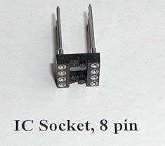


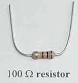
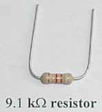
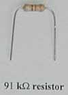
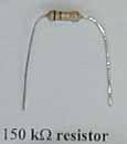
114 AMP PARTS 10
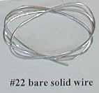
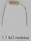
115 11
116 Building the AMP (Amplifier) Report: After you have made and tabulated your measurements of input and output voltages for the amplifier, plot the output voltage as a function of input voltage. Determine the gain of the amplifier in the region where the response is linear and compare your value with the theoretical expectation. Does the gain remain constant over the whole range of input voltages? Problem 1: Amplification A negative feedback circuit in an amplifier circuit is shown in the figure below. In this circuit, the resistors have the values R 1 = 9.1kΩ, R 2 = 100Ω, and the open loop amplification is A Pin 3 is non-inverting and pin 2 is inverting. a) What is the output voltage V of the op-amp in terms of the input voltage V in to pin 3, and out the voltage at pin 2, V 2, and the amplification A? (Note: all voltages are with respect to common). b) Derive an expression for the voltage at pin 2, in terms of R 1 and R 2. c) Derive an expression for the closed loop gain G = V V in in terms of R 1, R 2, and A. out d) Calculate the value of the gain G, clearly indicating any approximations you have made. 12
117 Problem 2: Calibration The calibration circuit for the amplifier is shown in the figure below. When the multimeter is set on the 250 mv scale the multimeter has a resistance of 5kΩ. a) When the 5kΩ pot is turned 2/3 of the way in the direction of the +6V line from the 6V end, what is the voltage difference between common C and the 5 kω pot slider? b) When the 5 kω pot is set as in part a), calculate the voltage difference between the common C and point D which is connected via a clip lead to the input A? c) What ouput voltage did you read when your pot was set as in part a) while you were calibrating your amplifier? 13
118 Experiment MW Microwaves Introduction Finding ways to generate ever-higher frequencies in an efficient and controllable way has been central in the evolution of radio and related technology. The military need for radar that could see airplanes in darkness and fog stimulated the development of efficient power sources at frequencies between 1 and 1GHz. Wavelengths between 1cm and 30cm called microwaves (because the size of the wavelengths was considered to be very small compared to, say, AM radio wavelengths that are hundreds of meters). Microwave radar and particularly its spin-off, the microwave oven, have made the expression -- zap it in the microwave part of ordinary speech. The simplest way of generating electromagnetic waves (and the earliest -- used by Hertz 120 years ago) is simply to charge and discharge a capacitor connected to a spark gap and antenna. The antenna is excited at its resonant frequency by high frequency Fourier components in the discharge current and radiates electromagnetic waves. Spark transmitters were extensively used in the early days of radio before the invention of electronic amplifiers. In this experiment you ll generate microwaves with a simple spark transmitter powered by your HVPS. Two pieces of wire will serve as a transmitting dipole antenna. You'll use another piece of wire as a receiving dipole antenna connected to your amplifier through a diode to detect the microwaves and to investigate their properties. Figure 1: Spark-gap transmitter 1
119 Spark gap and Antenna Your transmitter is based on the adjustable spark gap of Experiment EB (Electrical Breakdown) which you recently worked on. You need only add a 33 pf capacitor across the tungsten rods and two lengths of #12 wire that you will solder to the solder lugs (mounted on the brass screws ) which make up the two halves of a dipole antenna (see Figure 1). Each length is 31mm long. The capacitor is charged by your HVPS and discharges when its voltage reaches a value such that the electric field in the gap exceeds the breakdown field of air. After discharging, the capacitor charges up again through the 4 MΩ of resistance outside the HVPS plus its 0.5 MΩ internal resistance. The time constant τ = RC = ( Ω )( F) = s. So the charging and breakdown cycle will recur at a frequency This will generate bursts of radiation. 1 f osc = = 6.7kHz. τ The frequency of the radiation is determined by the time it takes charge to flow on the antenna. Just before breakdown the two halves of the antenna are charged + and - forming an electric dipole. There is an electric field around this dipole. During the short time that the capacitor discharges, the electric field decays and large currents flow producing magnetic fields. These currents flow through the gap and charge the antenna with the opposite polarity. The oscillations damp out as energy is dissipated and some of the energy is radiated with the period T = 4l c where l is the length of 12 of the dipole and c is the speed of light. The charge travels a distance 4l going from + to - and back from - to +. In this experiment we ll make l = 31 mm so the frequency radiated, f rad = 1 = c = Hz = 2.4 GHz T 4 l Therefore the antenna will emit bursts of damped radiation (every s ) at frequencies around 2.4GHz. The range of frequencies depends on the quality, Q, of the antenna. (The quality factor of a resonant system, or the antenna is: Q = (2πf )(average energy stored average power dissipated), for each cycle. The quality factor also measures the width of the resonance, Q = quality factor antenna gives a narrow range of generated frequencies.) f f. So a high The spark generates other frequencies as well (as a nearby radio will show) and to minimize the radiation of these we put two 1 MΩ resistors close to the capacitor. 2

120 Building the Transmitter Solder the 33 pf capacitor to the leads of the 1 MΩ resistors (see Figure 2). Make the capacitor leads as short and direct as possible without hindering the adjustment of the gap. Cut two 31mm long straight pieces of bare #12 copper wire (from the piece of plastic insulated wire in the Red Box) and solder them to the solder lugs which protrude above the end of the clothespin. The ends of the wire should extend (at most) a few millimeters from the end of the solder lug. This relatively heavy wire minimizes resistance and maximizes Q. You can strip the insulation from the plastic insulated household wire by stripping a short length and, then holding the bare copper with pliers, pulling off the insulation. Receiving Antenna This is made of a single piece of wire made into a one-turn loop with two ends sticking out from the plane of the loop, each a 1/4 wavelength long. The microwave emf developed across the loop is rectified by a diode and the resulting dc is fed to your amplifier through a shielded cable. The loop has two purposes: it provides mechanical stability for the antenna and it acts as a one-turn inductor which prevents low frequency fields from affecting your observations. The electric fields of the microwaves when parallel to the receiving antenna will cause current to flow. As in the transmitting antenna, the dimension of the receiving dipole makes it broadly resonant at 2 to 3 gigahertz. Voltages developed across the loop are rectified by the diode rectifier that passes only one half-wave of each oscillation to make a train of dc pulses. The capacitance of the wires smooth out the rapid variations and leaves an envelope of the decaying pulses of microwaves. These pulses drive the amplifier, which increases their voltage and smooths out the faster variations. The output of the amplifier then drives the slowresponding multimeter. Figure 2: Receiving Antenna 3
.")
121 Building the Receiving Antenna Take the insulation off another piece of #12 wire (strip a little and holding the copper with pliers, pull the insulation off) and wrap it around a pen so as to make a loop, about mm in diameter, in the middle of the wire. Bend the ends of the wire so that the plane of the loop is perpendicular to the line form by the two ends of the wire (Figure 2). Make the bends as close as possible to the loop. Trim the length of each half of the antenna to 31mm as measured from the plane of the loop. The overall length will be about 75mm, allowing for the wire thickness and bends. The shielded cable is actually a two conductor shielded wire. Prepare the shielded lead by stripping off about 30 mm of the outer plastic covering. Inside you will find two inner wires (red and white, or red and black) surrounded by a bare metal shield. You may also see a stranded bare wire between the aluminum shield and the plastic covering. (See Figure 3). In order to strip the plastic covering, grab the wire with pliers about 30 mm from one end, use your wire stripper first to cut a groove in the insulation by turning it, and then lever off the insulation. It's important not to damage the inner wires. If you don't succeed at first, practice taking off shorter lengths of insulation (fortunately the exact length of this lead doesn't matter). Figure 3: Two conductor cable Solder a short ( 10mm ) piece of bare wire to the antenna immediately next to each side of the loop and as close to it as feasible. Solder one of the wires from the loop to the bare stranded wire or the shield (this is the ground). Solder the wire from the black marked end of the 1N5712 diode to the inner red wire. Solder the other end of the diode to the remaining wire from the loop. (We will not connect anything to the black or white inner wire). Avoid overheating the diode. Use black tape to insulate the diode and its leads from the bare stranded wire. A short here will prevent the antenna from transmitting a signal. Then wrap aluminum foil around the assembly to shield it, making sure that the foil is in contact with the bare stranded wire that acts as ground. (See Figure 4). 4
122 Figure 4: Receiving Antenna On the other end of the two conductor shielded wire, connect the inner red wire to the input of your amplifier, A. Connect the bare stranded wire to the common, C. Check to see that your diode is good by measuring the resistance on the R x 1K scale of the MMM. If you connect your clip leads with the positive lead on the red wire and the negative lead on the bare stranded wire, you should measure a resistance of 10 kω. If you connect the leads the other way, you should measure a resistance of. The diode can be easily popped if you are not careful. Avoid allowing the receiving antenna to touch the transmitting antenna. If at any time during the experiment, you are not receiving signal, check your diode by measuring its resistance. Setting up the Apparatus Stick the transmitter down on your desk with tape about 0.5m from either side of the desk. Have the adjusting nut of the spark gap facing you. Connect the gap to the HVPS. Place the HVPS out of the way near the edge of the desk. Tape aluminum foil to one of the covers of a textbook and stand it up about 8cm behind the spark gap transmitter to act as a reflector. Put your amplifier on the opposite side of the transmitter and somewhat back so that you can explore the radiation field with the receiving antenna. You should be able to move the receiving antenna from a few centimeters from the transmitter to as far as the shielded wire will let you go on the other side -- for larger distances, move the amplifier. You will notice that if the receiving antenna is too close to the transmitter, the signal will saturate the amplifier. You may find that when the receiving antenna is between 15cm and 30cm away the transmitter, the signal will not saturate the amplifier. Use one MMM to measure the HVPS output (1000DCV range) and the other MMM to measure the amplifier output (250mV or 5DCV range). Their long leads should be kept out of the way. 5

123 Figure 6: Reflector behind transmitter 6
Exercise MM About the Multimeter
 Exercise MM About the Multimeter Introduction Our world is filled with devices that contain electrical circuits in which various voltage sources cause currents to flow. Electrical currents generate heat,
Building the LVPS Low Voltage Power Supply
 Introduction Building the LVPS Low Voltage Power Supply Low voltage is one of those relative terms up to 25 volts [V ] dc is low, and most people would call 1000V high. Power supplies provide energy from
AC/DC ELECTRONICS LABORATORY
 Includes Teacher's Notes and Typical Experiment Results Instruction Manual and Experiment Guide for the PASCO scientific Model EM-8656 012-05892A 1/96 AC/DC ELECTRONICS LABORATORY 1995 PASCO scientific
The Wave (K-MOD103) GUITAR DWELL REVERB REVERB SWITCH ON OUT OFF
 GUITAR DWELL REVERB REVERB SWITCH ON OUT OFF") The Wave (K-MOD103) OUT IN GUITAR IN DWELL REVERB REVERB SWITCH ON GUITAR OUT POWER ON OFF OFF Please note, there are no labels for this kit. The controls, switches and connectors have only been labeled
The Wave (K-MOD103) OUT IN GUITAR IN DWELL REVERB REVERB SWITCH ON GUITAR OUT POWER ON OFF OFF Please note, there are no labels for this kit. The controls, switches and connectors have only been labeled
DC CIRCUITS AND OHM'S LAW
 July 15, 2008 DC Circuits and Ohm s Law 1 Name Date Partners DC CIRCUITS AND OHM'S LAW AMPS - VOLTS OBJECTIVES OVERVIEW To learn to apply the concept of potential difference (voltage) to explain the action
Electrical Measurements
 Electrical Measurements INTRODUCTION In this section, electrical measurements will be discussed. This will be done by using simple experiments that introduce a DC power supply, a multimeter, and a simplified
Pre-Laboratory Assignment
 Measurement of Electrical Resistance and Ohm's Law PreLaboratory Assignment Read carefully the entire description of the laboratory and answer the following questions based upon the material contained
Laboratory 1 page 1 of 13
 Laboratory 1 page 1 of 13 Laboratory 1 Using the Meter, Breadboard, and Soldering Iron Introduction Welcome to the Bio Electronics Laboratory (BEL) located in B10 Benedum Hall. In this first lab assignment,
UNIVERSITY OF NORTH CAROLINA AT CHARLOTTE Department of Electrical and Computer Engineering
 UNIVERSITY OF NORTH CAROLINA AT CHARLOTTE Department of Electrical and Computer Engineering EXPERIMENT 2 BASIC CIRCUIT ELEMENTS OBJECTIVES The purpose of this experiment is to familiarize the student with
Lab 4 OHM S LAW AND KIRCHHOFF S CIRCUIT RULES
 57 Name Date Partners Lab 4 OHM S LAW AND KIRCHHOFF S CIRCUIT RULES AMPS - VOLTS OBJECTIVES To learn to apply the concept of potential difference (voltage) to explain the action of a battery in a circuit.
Assembly Instructions for the 1.5 Watt Amplifier Kit
 Assembly Instructions for the 1.5 Watt Amplifier Kit 1.) All of the small parts are attached to a sheet of paper indicating both their value and id. 2.) Leave the parts affixed to the paper until you are
Assembly Instructions
 Assembly Instructions For the SSQ-2F 3.1 MHz Rife Controller Board Kit v1.41 Manual v1.00 2012 by Ralph Hartwell Spectrotek Services GENERAL ASSEMBLY INSTRUCTIONS Arrange for a clean work surface with
AM RADIO KIT MODEL AM-780K. Assembly and Instruction Manual
 AM RADIO KIT MODEL AM-780K Assembly and Instruction Manual Elenco Electronics, Inc. Copyright 2007, 1999 by Elenco Electronics, Inc. All rights reserved. Revised 2007 REV-F 753108 No part of this book
Pacific Antenna Field Strength Indicator Kit
 Pacific Antenna Field Strength Indicator Kit Description The Field Strength Indicator kit from Pacific Antenna provides a visual way to monitor the presence and relative strength RF fields through the
Lab 3 DC CIRCUITS AND OHM'S LAW
 43 Name Date Partners Lab 3 DC CIRCUITS AND OHM'S LAW AMPS + - VOLTS OBJECTIVES To learn to apply the concept of potential difference (voltage) to explain the action of a battery in a circuit. To understand
APPENDIX D DISCUSSION OF ELECTRONIC INSTRUMENTS
 APPENDIX D DISCUSSION OF ELECTRONIC INSTRUMENTS DC POWER SUPPLIES We will discuss these instruments one at a time, starting with the DC power supply. The simplest DC power supplies are batteries which
Value Location Qty Transistors 2N5485 Q1, Q2, 4 Q3, Q4 2N5087 Q5 1. Trim Pots 250k VTRIM 1. Potentiometers C500k Speed 1. Toggle Switch On/On Vibe 1
 P-90 BUILD INSTRUCTIONS Thank you for your purchase of our P-90 kit! We have completely redesigned our entire line of kits to be the most user friendly, while still maintaining their same great sound!
Physics 3330 Experiment #2 Fall DC techniques, dividers, and bridges
 Physics 3330 Experiment #2 Fall 2002 DC techniques, dividers, and bridges Purpose You will gain a familiarity with the circuit board and work with a variety of DC techniques, including voltage dividers,
Lab 2 Electrical Safety, Breadboards, Using a DMM
 Lab 2 Electrical Safety, Breadboards, Using a DMM Objectives concepts 1. Safety hazards related to household electricity and electronics equipment 2. Differences between schematic and breadboard representations
University of Jordan School of Engineering Electrical Engineering Department. EE 204 Electrical Engineering Lab
 University of Jordan School of Engineering Electrical Engineering Department EE 204 Electrical Engineering Lab EXPERIMENT 1 MEASUREMENT DEVICES Prepared by: Prof. Mohammed Hawa EXPERIMENT 1 MEASUREMENT
PAC-12 Kit Contents. Tools Needed Soldering iron Phillips screwdriver Wire stripper Wrenches, 7/16 and 1/2 Terminal crimp tool Pliers Solder
 PAC-2 Kit Contents Part Quantity Screws: 8/32 x 3/8 Screws: 8-32 x 5/6 Screw: 8-32 x /4 #8 internal tooth washers #8 solder lug ring terminals Bolt: Aluminum, /4-20 x.5 /4 internal tooth washer Nut: Aluminum
1. The coulomb is a unit of. A. charge B. voltage C. energy D. capacitance E. current. 2. The following is not true about voltage:
 BioE 1310 - Review 1 - DC 1/16/2017 Instructions: On the Answer Sheet, enter your 2-digit ID number (with a leading 0 if needed) in the boxes of the ID section. Fill in the corresponding numbered circles.
QUASAR ELECTRONICS KIT No DRILL SPEED CONTROLLER
 QUASAR ELECTRONICS KIT No. 1074 DRILL SPEED CONTROLLER General Description If you work with an electric drill and unless you are lucky enough to own one of the most sophisticated models with speed control,
Lecture 3.10 ELECTRICITY Alternating current Electrical safety
 Lecture 3.1 ELECTRCTY Alternating current Electrical safety Alternating Current (ac) Batteries are a source of steady or direct voltage. Current in a circuit powered by a battery is also steady and is
EE 210: CIRCUITS AND DEVICES
 EE 210: CIRCUITS AND DEVICES LAB #3: VOLTAGE AND CURRENT MEASUREMENTS This lab features a tutorial on the instrumentation that you will be using throughout the semester. More specifically, you will see
Experiment 2. Ohm s Law. Become familiar with the use of a digital voltmeter and a digital ammeter to measure DC voltage and current.
 Experiment 2 Ohm s Law 2.1 Objectives Become familiar with the use of a digital voltmeter and a digital ammeter to measure DC voltage and current. Construct a circuit using resistors, wires and a breadboard
Module 1, Lesson 2 Introduction to electricity. Student. 45 minutes
 Module 1, Lesson 2 Introduction to electricity 45 minutes Student Purpose of this lesson Explanations of fundamental quantities of electrical circuits, including voltage, current and resistance. Use a
Wiring Techniques for Wiring a Lamp
 Supplies and Tools that you will need: Provided in your kit: Polarized lamp plug, 9 of SPT-1 18 AWG parallel lamp cord, bushings and grommets Items that you will need to provide: Phillips screwdriver,
Current, resistance, and Ohm s law
 Current, resistance, and Ohm s law Apparatus DC voltage source set of alligator clips 2 pairs of red and black banana clips 3 round bulb 2 bulb sockets 2 battery holders or 1 two-battery holder 2 1.5V
DIGITAL MULTIMETER CONTENTS DIGITAL MULTIMETER CONTENTS
 CONTENTS CONTENTS CONTENTS 1. SAFETY INFORMATION...1 1.1 Preliminary...1 1.2 Dos and don ts...2 1.3 Symbols...3 1.4 Precautions...4 2. DESCRIPTION...5 2.1 Names of parts...6 2.2 Switches, buttons and input
AME140 Lab #2 INTRODUCTION TO ELECTRONIC TEST EQUIPMENT AND BASIC ELECTRONICS MEASUREMENTS
 INTRODUCTION TO ELECTRONIC TEST EQUIPMENT AND BASIC ELECTRONICS MEASUREMENTS The purpose of this document is to guide students through a few simple activities to increase familiarity with basic electronics
Syllabus OP49 Test electrical conduction in a variety of materials, and classify each material as a conductor or insulator
 Physics: 14. Current Electricity Please remember to photocopy 4 pages onto one sheet by going A3 A4 and using back to back on the photocopier Syllabus OP49 Test electrical conduction in a variety of materials,
νµθωερτψυιοπασδφγηϕκλζξχϖβνµθωερτ ψυιοπασδφγηϕκλζξχϖβνµθωερτψυιοπα σδφγηϕκλζξχϖβνµθωερτψυιοπασδφγηϕκ χϖβνµθωερτψυιοπασδφγηϕκλζξχϖβνµθ
 θωερτψυιοπασδφγηϕκλζξχϖβνµθωερτψ υιοπασδφγηϕκλζξχϖβνµθωερτψυιοπασδ φγηϕκλζξχϖβνµθωερτψυιοπασδφγηϕκλζ ξχϖβνµθωερτψυιοπασδφγηϕκλζξχϖβνµ Physics θωερτψυιοπασδφγηϕκλζξχϖβνµθωερτψ Current and Electricity υιοπασδφγηϕκτψυιοπασδφγηϕκλζξχϖβν
Experiment 3 Ohm s Law
 Experiment 3 Ohm s Law The goals of Experiment 3 are: To identify resistors based upon their color code. To construct a two-resistor circuit using proper wiring techniques. To measure the DC voltages and
Building the Sawdust Regenerative Receiver
 Building the Sawdust Regenerative Receiver Introduction The Sawdust is a super regenerative receiver using the basic Armstrong design architecture. The receiver uses one toroidal transformer to provide
B EE Laboratory 1 - Introduction to Circuit Analysis
 Page 1 B EE 215 Introduction to Circuit Analysis Authors D. Wilson, R.D. Christie, W.R. Lynes, K.F. Böhringer, M. Ostendorf Objectives At the end of this lab, you will be able to: Check continuity with
EGR Laboratory 1 - Introduction to Circuit Analysis
 EGR 215 Laboratory 1 Introduction to Circuit Analysis Authors D. Wilson, R.D. Christie, W.R. Lynes, K.F. Böhringer, M. Ostendorf of the University of Washington Objectives At the end of this lab, you will
EE 233 Circuit Theory Lab 3: First-Order Filters
 EE 233 Circuit Theory Lab 3: First-Order Filters Table of Contents 1 Introduction... 1 2 Precautions... 1 3 Prelab Exercises... 2 3.1 Inverting Amplifier... 3 3.2 Non-Inverting Amplifier... 4 3.3 Integrating
Building the Sawdust Regenerative Receiver
 Building the Sawdust Regenerative Receiver Introduction The Sawdust is a super regenerative receiver using the basic Armstrong design architecture. The receiver uses one toroidal transformer to provide
Physics 4BL: Electricity and Magnetism Lab manual. UCLA Department of Physics and Astronomy
 Physics 4BL: Electricity and Magnetism Lab manual UCLA Department of Physics and Astronomy Last revision April 16, 2017 1 Lorentz Force Laboratory 2: Lorentz Force In 1897, only 120 years ago, J.J. Thomson
South Pasadena A.P. Physics Chapter Electric Current & DC Circuits Date / / Period Electricity Practice Test
 South Pasadena A.P. Physics Name Chapter 18-19 Electric Current & DC Circuits Date / / Period 1 2 3 4 Electricity Practice Test Electric Current I = Q/t 1. A charge of 30 Coulombs passes through a 24-ohm
Lab 1: Basic Lab Equipment and Measurements
 Abstract: Lab 1: Basic Lab Equipment and Measurements This lab exercise introduces the basic measurement instruments that will be used throughout the course. These instruments include multimeters, oscilloscopes,
SoftRock v6.0 Builder s Notes. May 22, 2006
 SoftRock v6.0 Builder s Notes May 22, 2006 Be sure to use a grounded tip soldering iron in building the v6.0 SoftRock circuit board. The soldering iron needs to have a small tip, (0.05-0.1 inch diameter),
Cable & Bolt Cutters. F o r P. r o f e. s s i o. n a l s. .. S i. n c e 1
 F o r P Cable & Bolt Cutters r o f e s s i o n a l s. Klein meets and exceeds the highest of standards to create great cable and bolt cutters. Offering greater cutting power, clean and precise cuts, and
Experiment 3. Ohm s Law. Become familiar with the use of a digital voltmeter and a digital ammeter to measure DC voltage and current.
 Experiment 3 Ohm s Law 3.1 Objectives Become familiar with the use of a digital voltmeter and a digital ammeter to measure DC voltage and current. Construct a circuit using resistors, wires and a breadboard
Repairing your Porsche 928 Central Warning System (CWS) controller
 controller") Repairing your Porsche 928 Central Warning System (CWS) controller Disclaimer: This procedure is for a 1984 Porsche 928 S controller. Overview: Under the left foot pedal (dead pedal) of the Porsche 928
Repairing your Porsche 928 Central Warning System (CWS) controller Disclaimer: This procedure is for a 1984 Porsche 928 S controller. Overview: Under the left foot pedal (dead pedal) of the Porsche 928
Simple Circuits Experiment
 Physics 8.02T 1 Fall 2001 Simple Circuits Experiment Introduction Our world is filled with devices that contain electrical circuits in which various voltage sources cause currents to flow. We use radios,
A Pretty Good Crystal Set Mark II
 A Pretty Good Crystal Set Mark II By Al Klase, N3FRQ, http://www.skywaves.ar88.net/ This is a revised version of the original New Jersey Antique Radio Club PGXS with minor changes to improve performance
Introduction to Soldering
 Introduction to Soldering The Soldering Iron American Standard Wire Gage (AWG) Solder The Soldering Process Stripping & Tinning Wire Connecting/Soldering Wire Component Soldering De-Soldering Lab Exercise
Standard Kit #1 (5-way switch)
") Standard Kit #1 (5-way switch) Please Read All Instructions Before Beginning. Tools you will need: Soldering Iron (35 watt preferably) Solder Wet Sponge Wire Clippers 3/8 Drill Bit 1/4 Drill Bit Variable
Standard Kit #1 (5-way switch) Please Read All Instructions Before Beginning. Tools you will need: Soldering Iron (35 watt preferably) Solder Wet Sponge Wire Clippers 3/8 Drill Bit 1/4 Drill Bit Variable
Explorer Wiring Kit (assembled)
") Explorer Wiring Kit (assembled) For Vintage, Firestorm & Standard Series Please Read All Instructions Before Beginning. Tools you will need: Soldering Iron (35 watt preferably) Solder Wet Sponge Wire Clippers
Explorer Wiring Kit (assembled) For Vintage, Firestorm & Standard Series Please Read All Instructions Before Beginning. Tools you will need: Soldering Iron (35 watt preferably) Solder Wet Sponge Wire Clippers
Value Location Qty Potentiometers C1M Distortion 1 A10k Volume 1. Footswitch 3PDT SW1 1. Jacks 1/4 Mono 2 DC Power 1
 Distortion BUILD INSTRUCTIONS Thank you for your purchase of our Distortion+ kit! We have completely redesigned our entire line of kits to be the most user friendly, while still maintaining their same
Find a place where you can work through completion, without disturbing your
 Scan by Manual Manor ARIES SYSTEM 300 MUSIC SYNTHESIZER Page I of 4 MODULE AR-334 SEQUENCER ASSEMBLY INSTRUCTIONS It is recommended that you do the following before you proceed: Find a place where you
DIGIT & POINTER MULTIMETER
 CONTENTS DIGIT & POINTER MULTIMETER OPERATOR S MANUAL 1. SAFETY INFORMATION 1 1.1 PRELIMINARY 1 1.2 DURING USE 2 1.3 SYMBOLS 3 1.4 MAINTENANCE 3 2. DESCRIPTION 4 2.1 NAMES OF COMPONENTS 4 2.2 FUNCTION
General Radio 1840-A. Output Power Meter
 PRECISION INSTRUMENTS FOR TEST AND MEASUREMENT General Radio 1840-A Output Power Meter User and Service Manual WARNING OBSERVE ALL SAFETY RULES WHEN WORKING WITH HIGH VOLTAGES OR LINE VOLTAGES. Dangerous
CONTENTS. SAFETY PRECAUTIONS: Before use, read the following safety precautions
 CONTENTS [1] SAFETY PRECAUTIONS: Before use, read the following safety precautions 2 [2] APPLICATION AND FEATURES 5 [3] NAME OF COMPONENT UNITS 6 [4] DESCRIPTION OF FUNCTIONS 8 [5] MEASUREMENT PROCEDURE
FUNCTION GENERATOR KIT
 FUNCTION GENERATOR KIT MODEL FG-500K Assembly and Instruction Manual Elenco Electronics, Inc. Copyright 2005 by Elenco Electronics, Inc. All rights reserved. Revised 2005 REV-B 753069 No part of this book
Specimen Products Single Ended Stereo Amp Instruction Book
 Specimen Products Single Ended Stereo Amp Instruction Book Specimen tube amplifier designs are informed by decades of servicing and building musical instrument amps. As a result of being subjected to the
Overtravel of 3.5 mm max. Power source DC D5C-1DS0 D5C-1DP0 D5C-1DA0 AC D5C-1AS0 D5C-1AP0 D5C-1AA0 Antenna only D5C-00S0 D5C-00P0 D5C-00A0
 Touch Switch Unique 18 mm Capacitive Touch Switch with Choice of Three Actuators is Activated with Only a Very Slight Physical Contact Lightweight objects, such as thin wire or foil can be accurately detected.
Experiment 2 Soldering Parallel and Series Circuits and using the Digital Multimeter
 Experiment 2 Soldering Parallel and Series Circuits and using the Digital Multimeter Introduction Soldering is the most common means of joining components to each other or to circuit boards in electronics.
MEASUREMENTS & INSTRUMENTATION ANALOG AND DIGITAL METERS
 MEASUREMENTS & INSTRUMENTATION ANALOG AND DIGITAL METERS ANALOG Metering devices Provides monotonous (continuous) movement. ELECTRICAL MEASURING INSTRUMENTS ANALOG METERS A d Arsonval galvanometer (Moving
OPERATOR S MANUAL Model 160 Volt-Ohm-Milliammeter
 OPERATOR S MANUAL Model 160 Volt-Ohm-Milliammeter About this Manual To the best of our knowledge and at the time written, the information contained in this document is technically correct and the procedures
V6.2 SoftRock Lite Builder s Notes. November 17, 2006
 V6.2 SoftRock Lite Builder s Notes November 17, 2006 Be sure to use a grounded tip soldering iron in building the v6.2 SoftRock circuit board. The soldering iron needs to have a small tip, (0.05-0.1 inch
OPERATOR S INSTRUCTION MANUAL M-2625 AUTO RANGING DIGITAL MULTIMETER
 OPERATOR S INSTRUCTION MANUAL M-2625 AUTO RANGING DIGITAL MULTIMETER with Temperature Probe Copyright 2007 Elenco Electronics, Inc. Contents 1. Safety Information 3,4 2. Safety Symbols 5 3. Front Plate
THE RING RESONATOR (K-975)
") THE RING RESONATOR (K-975) OUTPUT BOOST The Ring Resonator An Octave Up Fuzz Modkitsdiy.com 9 VDC CENTER (-) ADAPTER TO AMP IN FROM GUITAR OUT Unplug when not in use to save battery life. Use these instructions
THE RING RESONATOR (K-975) OUTPUT BOOST The Ring Resonator An Octave Up Fuzz Modkitsdiy.com 9 VDC CENTER (-) ADAPTER TO AMP IN FROM GUITAR OUT Unplug when not in use to save battery life. Use these instructions
Introduction to the Laboratory
 Memorial University of Newfoundland Department of Physics and Physical Oceanography Physics 2055 Laboratory Introduction to the Laboratory The purpose of this lab is to introduce you to some of the equipment
Chapter 2: Electricity
 Chapter 2: Electricity Lesson 2.1 Static Electricity 1 e.g. a polythene rod Lesson 2.3 Electric current 1 I = Q / t = 80 / 16 = 5 A 2 t = Q / I = 96 / 6 = 16 s 1b e.g. a metal wire 2 If static charge begins
Experiment 1: Circuits Experiment Board
 01205892C AC/DC Electronics Laboratory Experiment 1: Circuits Experiment Board EQUIPMENT NEEDED: AC/DC Electronics Lab Board: Wire Leads Dcell Battery Graph Paper Purpose The purpose of this lab is to
Resistance and Ohm s law
 Resistance and Ohm s law Objectives Characterize materials as conductors or insulators based on their electrical properties. State and apply Ohm s law to calculate current, voltage or resistance in an
Lab Equipment EECS 311 Fall 2009
 Lab Equipment EECS 311 Fall 2009 Contents Lab Equipment Overview pg. 1 Lab Components.. pg. 4 Probe Compensation... pg. 8 Finite Instrumentation Impedance. pg.10 Simulation Tools..... pg. 10 1 - Laboratory
DC Circuits, Ohm's Law and Multimeters Physics 246
 DC Circuits, Ohm's Law and Multimeters Physics 246 Theory: In this lab we will learn the use of multimeters, verify Ohm s law, and study series and parallel combinations of resistors and capacitors. For
AC/DC POWER SUPPLY KIT
 AC/DC POWER SUPPLY KIT MODEL K-11 Assembly and Instruction Manual ELENCO Copyright 2016, 1989 by ELENCO All rights reserved. Revised 2016 REV-O 753211 No part of this book shall be reproduced by any means;
Telecaster Wiring Kits Please Read All Instructions Before Beginning. Tools you will need: Soldering tips: Removing Current Wiring: Step 1. Step 2.
 Telecaster Wiring Kits Please Read All Instructions Before Beginning. Tools you will need: Soldering Iron (35 watt preferably) Solder Wet Sponge Wire Clippers Wire Strippers 3/8 Drill Bit 5/32 Drill Bit
Resistance and Ohm s Law R V I. 1 ohm = 1 volt ampere
 Resistance and Ohm s Law If you maintain an electric potential difference, or voltage V, across any conductor, an electric current occurs. In general, the magnitude of the current depends on the potential
The Discussion of this exercise covers the following points:
 Exercise 5 Resistance and Ohm s Law EXERCISE OBJECTIVE When you have completed this exercise, you will be familiar with the notion of resistance, and know how to measure this parameter using an ohmmeter.
Standard Kit #1 (3-way switch)
") Standard Kit #1 (3-way switch) Please Read All Instructions Before Beginning. Tools you will need: Soldering Iron (35 watt preferably) Solder Wet Sponge Wire Clippers 3/8 Drill Bit 1/4 Drill Bit Variable
Standard Kit #1 (3-way switch) Please Read All Instructions Before Beginning. Tools you will need: Soldering Iron (35 watt preferably) Solder Wet Sponge Wire Clippers 3/8 Drill Bit 1/4 Drill Bit Variable
Soldering is easy. here's how to do it. Andie Nordgren (Comics adaptation) Jeff Keyzer. by: Mitch Altman (soldering wisdom) (Layout and editing)
 Jeff Keyzer. by: Mitch Altman (soldering wisdom) (Layout and editing)") Soldering is easy here's how to do it by: Mitch Altman (soldering wisdom) Andie Nordgren (Comics adaptation) Jeff Keyzer (Layout and editing) Download this comic book and share it with your friends! Distribute
Soldering is easy here's how to do it by: Mitch Altman (soldering wisdom) Andie Nordgren (Comics adaptation) Jeff Keyzer (Layout and editing) Download this comic book and share it with your friends! Distribute
THE THUNDERDRIVE (K-950)
") THE THUNDERDRIVE (K-950) OUTPUT DISTORTION Unplug when not in use to save battery life. TO AMP IN The Thunderdrive Modkitsdiy.com FROM GUITAR OUT Use these instructions to learn: How to build an effects
THE THUNDERDRIVE (K-950) OUTPUT DISTORTION Unplug when not in use to save battery life. TO AMP IN The Thunderdrive Modkitsdiy.com FROM GUITAR OUT Use these instructions to learn: How to build an effects
ECE 145A/218A, Lab Project #1a: passive Component Test.
 ECE 145A/218A, Lab Project #1a: passive Component Test. September 28, 2017 OVERVIEW... 2 GOALS:... 2 PRECAUTIONS TO AVOID INSTRUMENT DAMAGE... 2 SAFETY PRECAUTIONS... 2 READING:... 3 NETWORK ANALYZER CALIBRATION...
SoftRock v6.0 Builder s Notes. April 6, 2006
 SoftRock v6.0 Builder s Notes April 6, 006 Be sure to use a grounded tip soldering iron in building the v6.0 SoftRock circuit board. The soldering iron needs to have a small tip, (0.05-0. inch diameter),
Pacific Antenna Low Pass Filter Kit
 Pacific Antenna Low Pass Filter Kit Description Many basic transmitter and/or transceiver designs have minimal filtering on their output and frequently have significant harmonic content in their signals.
YAL. 12 Electricity. Assignments in Science Class X (Term I) IMPORTANT NOTES
 IMPORTANT NOTES") Assignments in Science Class X (Term I) 12 Electricity IMPORTANT NOTES 1. There are two kinds of electric charges i.e., positive and negative. The opposite charges attract each other and the similar charges
Assignments in Science Class X (Term I) 12 Electricity IMPORTANT NOTES 1. There are two kinds of electric charges i.e., positive and negative. The opposite charges attract each other and the similar charges
Cornerstone Electronics Technology and Robotics I Week 19 Soldering Tutorial
 Cornerstone Electronics Technology and Robotics I Week 19 Soldering Tutorial Administration: o Prayer o Turn in quiz o Using fixed resistors design and build a voltage divider divides 5 volts in half.
Installation Instructions
 READ BEFORE INSTALLING UNIT For Slider Casement Air Conditioners To avoid risk of personal injury, property damage, or product damage due to the weight of this device and sharp edges that may be exposed:
AVM360 Analog multimeter OPERATION MANUAL GEBRUIKERSHANDLEIDING MANUEL D UTILISATEUR
 Analog multimeter OPERATION MANUAL GEBRUIKERSHANDLEIDING MANUEL D UTILISATEUR Analogue Multimeter 1. Description Your is a professional analogue multimeter. It is ideally suited for field, lab, shop, and
LED Field Strength Indicator Kit
 LED Field Strength Indicator Kit Description The Field Strength Indicator kit from Qrpkits.com provides a visual way to monitor RF fields through the brightness of an LED. It will respond to RF fields
Electronics Review 2 Cornerstone Electronics Technology and Robotics II
 Electronics Review 2 Cornerstone Electronics Technology and Robotics II Administration: o Prayer o Bible Verse Hacksaws: o Vertical and horizontal positions o Hacksaw blade must be positioned with the
Laboratory 2 (drawn from lab text by Alciatore)
") Laboratory 2 (drawn from lab text by Alciatore) Instrument Familiarization and Basic Electrical Relations Required Components: 2 1k resistors 2 1M resistors 1 2k resistor Objectives This exercise is designed
Laboratory 2 (drawn from lab text by Alciatore) Instrument Familiarization and Basic Electrical Relations Required Components: 2 1k resistors 2 1M resistors 1 2k resistor Objectives This exercise is designed
Quickstart Antenna. Figure 1: Antenna Parts List
 Quickstart Antenna Got to the website (WsprWithoutTears.com) for more information. Parts List Check the parts received against the parts listed below. Part Value wire 42-0 ft 22 ga wire coax 5 ft RG-174
A short, off-center fed dipole for 40 m and 20 m by Daniel Marks, KW4TI
 A short, off-center fed dipole for 40 m and 20 m by Daniel Marks, KW4TI Version 2017-Nov-7 Abstract: This antenna is a 20 to 25 foot long (6.0 m to 7.6 m) off-center fed dipole antenna for the 20 m and
INSPIRE VLF-3 Rev #1C Receiver Kit ASSEMBLY INSTRUCTIONS
 INSPIRE VLF-3 Rev #1C Receiver Kit ASSEMBLY INSTRUCTIONS The following assembly instructions should be followed carefully. The INSPIRE VLF-3 receiver kit is NOT a simple electronic assembly. If you follow
Assembly Instructions: Kit #5
 Assembly Instructions: Kit #5 1. Insert the T-pin into one of the caps. 2. Insert the rotor core into the same cap as shown below. Apply some pressure to push the rotor core approximately 1/2" (10-12 mm)
ELECTRICAL CONNECTIONS
 ELECTRICAL CONNECTIONS Lesson 13 EET 150 Electrical Connections Learning Objectives In this lesson you will: see different methods of making electrical connections. learn a procedure for making soldered
THE STEP LADDER (K-978)
") THE STEP LADDER (K-978) Footswitch True-bypass = 0 db OUTPUT INPUT Ground shunt switching on the input jack keeps the amp quiet when unplugged from the Step Ladder. Attenuator Pot Full clockwise = 0 db
THE STEP LADDER (K-978) Footswitch True-bypass = 0 db OUTPUT INPUT Ground shunt switching on the input jack keeps the amp quiet when unplugged from the Step Ladder. Attenuator Pot Full clockwise = 0 db
METAL FABRICATION MECHANICAL
 METAL FABRICATION MECHANICAL Machine Screws Machine screws have a parallel thread and need a threaded hole to screw into. They come in a wide variety of materials and sizes and are used for semi-permanent
ECE 203 LAB 6: INVERTED PENDULUM
 Version 1.1 1 of 15 BEFORE YOU BEGIN EXPECTED KNOWLEDGE Basic Circuit Analysis EQUIPMENT AFG Oscilloscope Programmable Power Supply MATERIALS Three 741 Opamps TIP41 NPN power transistor TIP42 PNP power
WA3RNC 30 METER CRYSTALPLEXER TRANSMITTER KIT ASSEMBLY INSTRUCTIONS
 WA3RNC 30 METER CRYSTALPLEXER TRANSMITTER KIT ASSEMBLY INSTRUCTIONS Description The WA3RNC 30 Meter Crystalplexer is a low power crystal controlled QRP transmitter offering a significantly improved tuning
RF Current Meter Kit
 Kit When assembled, this kit provides you with a simple but effective means of measuring the current in antenna wires, and of looking for braid currents on coax feeders. The more current you can get flowing
SAFETY PRECAUTIONS: Before use, read the following safety precautions
 [1] SAFETY PRECAUTIONS: Before use, read the following safety precautions This instruction manual explains how to use your multimeter CD731, CD751 safely. Before use, please read this manual thoroughly.
Electronic Instrument Disadvantage of moving coil meter Low input impedance High loading error for low-voltage range voltmeter
 EIE 240 Electrical and Electronic Measurement Class 6, February 20, 2015 1 Electronic Instrument Disadvantage of moving coil meter Low input impedance High loading error for low-voltage range voltmeter