OPERATOR S MANUAL Model 160 Volt-Ohm-Milliammeter
|
|
|
- Sheryl Matthews
- 6 years ago
- Views:
Transcription

1 OPERATOR S MANUAL Model 160 Volt-Ohm-Milliammeter
2 About this Manual To the best of our knowledge and at the time written, the information contained in this document is technically correct and the procedures accurate and adequate to operate this instrument in compliance with its original advertised specifications. Notes and Safety Information This Operator s Manual contains warning symbols which alert the user to check for hazardous conditions. These appear throughout this manual where applicable, and are defined below. To ensure the safety of operating performance of this instrument, these instructions must be adhered to.! Warning, refer to accompanying documents. Caution, risk of electric shock.! This instrument is designed to prevent accidental shock to the operator when properly used. However, no engineering design can render safe an instrument which is used carelessly. Therefore, this manual must be read carefully and completely before making any measurements. Failure to follow directions can result in a serious or fatal accident. Technical Assistance SIMPSON ELECTRIC COMPANY offers assistance Monday through Friday 8:00 am to 4:30 pm Central Time. To receive assistance contact Technical Support or Customer Service at (715) Internet: Warranty and Returns SIMPSON ELECTRIC COMPANY warrants each instrument and other articles manufactured by it to be free from defects in material and workmanship under normal use and service, its obligation under this warranty being limited to making good at its factory or other article of equipment which shall within one (1) year after delivery of such instrument or other article of equipment to the original purchaser be returned intact to it, or to one of its authorized service centers, with transportation charges prepaid, and which its examination shall disclose to its satisfaction to have been thus defective; this warranty being expressly in lieu of all other warranties expressed or implied and of all other obligations or liabilities on its part, and SIMPSON ELECTRIC COM- PANY neither assumes nor authorizes any other persons to assume for it any other liability in connection with the sales of its products. This warranty shall not apply to any instrument or other article of equipment which shall have been repaired or altered outside the SIMPSON ELECTRIC COMPANY factory or authorized service centers, nor which has been subject to misuse, negligence or accident, incorrect wiring by others, or installation or use not in accord with instructions furnished by the manufacturer. SHOCK HAZARD: As defined in American National Standard, C39.5, Safety Requirements for Electrical & Electronic Measuring & Controlling Instrumentation, a shock hazard shall be considered to exist at any part involving a 2
3 potential in excess of 30 volts RMS (sine wave) or 42.4 volts DC or peak and where a leakage current from that part to ground exceeds 0.5 milliampere, when measured with an appropriate measuring instrument defined in Section of ANSI C
4 Contents 1. INTRODUCTION General Supplies & Accessories Safety Considerations Technical Data INSTALLATION Unpacking & Inspection Warranty Shipping Operating Procedure CONTROLS, CONNECTORS & INDICATORS Panel Description OPERATION Safety Precautions Zero Adjustment Measuring DC Voltages, 250 Millivolt Range Measuring DC Voltages, 1 V Range Measuring DC Voltages, 2.5 Through 500 V Ranges Measuring DC Voltages, 1,000 Volt Range Only Measuring AC Voltages, 2.5 Through 500 Volt Range Measuring AC Voltages, 1000 Volt Range Only Measuring Decibels Measuring Resistance Direct Current Measurement Measuring Direct Currents, 50 ma Range Measuring Direct Current, 0-1 Through ma Ranges BATTERY REPLACEMENT
5 1. INTRODUCTION 1.1 General The Simpson 160 Volt-Ohm-Milliammeter (hereafter referred to as the 160 or the Instrument) is a compact, easy-to-operate instrument used for measuring electrical characteristics of circuits and circuit components. The Instrument has a taut-band movement suspension with diode overload protection to provide long, trouble-free service. The 100 degree mirrored dial arc and knife edge pointer provide excellent readability and eliminate parallax errors. A polarity-reversing switch and a one-knob Function/Range selector simplify operation of the Instrument. The internal batteries are easily obtained and replaced. Most of the component parts are mounted on a printed circuit board. This helps ensure uniform performance, reduces maintenance and extends the useful life of the Instrument. 1.2 Supplies & Accessories All supplies and accessories required for the operation of the 160 are furnished with each Instrument and listed in Table Safety Considerations This Operator s Manual contains cautions and warnings alerting the user to hazardous operating and service conditions. CAUTION or WARNING symbols are placed throughout this publication, where applicable, and are defined on the inside cover of the manual under the heading SAFETY SYM- BOLS. Adherence to these instructions will help ensure safety of operating and servicing personnel and protect the instrument. 1.4 Technical Data DC Volts Ranges: Sensitivity: Rated Accuracy: AC Volts: Ranges: Sensitivity: Indication: Table 1-1. Technical Data 2.5, 10, 50, 250V; 0.25, 1.0 and 1000V on separate jacks. 20,000 per volt Within 2% DC and 3% AC of full scale on all ranges. 2.5, 20, 50, 250, 500V; 1,000V on separate jack. 5,000 per volt. Full-wave average-responding: calibrated in RMS for sinusoidal waveforms. * Frequency Response: Rated accuracy to 100,000 Hz on all ranges through 50V; to 20 khz on 250V range. 2-A. ** Rated Circuit- To-Ground Voltage: 1,000V AC/DC max. 5
6 * See typical Response Curves, Figure 1-1. ** Per ANSI C39.5 April 1974: The maximum voltage with respect to ground, which may safely and continuously be applied to the circuit of an instrument. Direct Current: Ranges: 1, 10, 100, 250, 500 ma; 50 A on separate jack. Rated Accuracy: Within 2% full scale, all ranges RESPONSE (db) RELATIVE TO 10KC VAC RANGE: 50VAC RANGE: 10 VAC RANGE: 25 VAC RANGE: SPEC. LIMITS: 250V RANGE 2.5 & 10V RANGES -2 50V RANGE K 100K 1M CYCLES PER SECOND Figure 1-1. Typical Frequency Response Curve DC Resistance Ranges: R x 1 R x 10 R x 100 R x 1K R x 10K Accuracy: Max. Voltage or Current Delivered: R x 1 R x 10 R x 100 R x 1K R x 10K db Ranges: Movement: Dial Arcs: Scale Length: 0-3,000 (30 center) 0-30,000 (300 center) 0-300,000 (3 K center) 0-3 M (30 K center) 30 M (300 K center) 3 arc 50 ma short circuit, 1.5V open circuit 5 ma short circuit, 1.5V open circuit 0.5 ma short circuit, 1.5V open circuit 0.75 ma short circuit, 22.5V open circuit ma short circuit, 22.5V open circuit 20 db to +10 db on 2.5 VAC range 8 db to +22 db on 10 VAC range +6 db to +36 db on 50 VAC range +20 db to +50 db on 250 VAC range Zero db referenced to 1 milliwatt at 600 Taut-Band 100 arc, 50 A full scale One arc for ohms, one arc for DC, two arcs for AC, one arc for db. 3.0 inches 6
7 Lead Reversal: Polarity Reverse Switch; on DC and ohms 10. Operating Position: Horizontal or vertical; rubber feet prevent slipping on moderate slopes. Batteries: 1.5 V AA penlight and No V Movement & Indicator Protection: Silicon double diode across movement terminals. Test Leads: Custom molded elbow terminals; 3 ft. flexible probe tips. Operating Temperature: 75 F for rated accuracy; less than 4% additional Range: error over the range of +25 F to +130 F. Size: 4-9/16 x 3-5/16 x 1-3/4 (inches) Weight: Approx. 12 oz., complete Table 1-2. Items and Accessories Supplied with This Instrument Description Cat. Number Probe Tip Test Leads Operator s Manual Table 1-3. Additional Accessories Description Cat. Number Padded Nylon Case Alligator Clip Leads INSTALLATION This section contains instructions for the installation and shipping of the 160. Included are unpacking and inspection procedures, warranty, shipping, and operating procedure. 2.1 Unpacking & Inspection Examine the shipping carton for signs of damage before unpacking. Unpack and inspect the Instrument for possible damage in shipment. If damaged, notify the carrier and supplier before using the Instrument. Check that all furnished items and accessories are included (Table 1-2). Save all shipping materials for future use. 2.2 Warranty The Simpson Electric Company warranty policy is printed on the inside front cover of this manual. Read it carefully before requesting a warranty repair. For all assistance, contact the nearest Authorized Service Center for instructions. If necessary, contact the factory directly, give full details of the difficulty and include the Instrument model number and date of purchase. Service data or shipping instructions will be mailed promptly. If an estimate of charges for nonwarranty or other service work is required, a maximum charge estimate 7
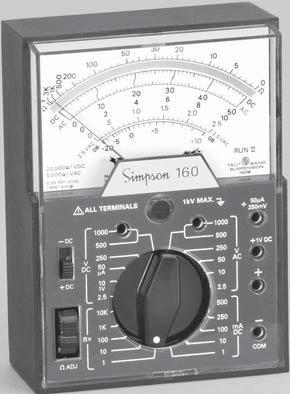
8 will be quoted. This charge will not be exceeded without prior approval. 2.3 Shipping Pack the Instrument carefully and ship it prepaid and insured to the proper destination. 2.4 Operating Procedure The Instrument may be operated in a horizontal or vertical position. 3. CONTROLS, CONNECTORS & INDICATORS All operating and adjustment controls, connectors, and indicators are described in this section along with a list (Table 3-1) describing their functions. Become familiar with each item before operating the Instrument. 3.1 Panel Description Table 3-1 lists all Controls, Connectors, and Indicators. 3K 1K DC AC 20,000 VDC 5,000 VAC 0 DB REF. LEVEL 1MW-600 -DC +DC V DC ALL TERMINALS A 10 1V K 1K RX ADJ ! db 2.5VAC kV MAX VAC db V AC DC AC +50 A 250MV +1V DC ma 100 DC _ 10 1 COM 0 RUN II TAUT BAND SUSPENSION 160M 3 1 Figure 3-1. Front Panel 8
9 Table 3-1. Controls, Connectors, and Indicators 1. Function and Range Switch: 2. Zero Ohms Adjust Control: This switch, located in the lower center of the panel, is used to select the desired current, voltage, or resistance function and appropriate range. This control, located at the lower left on the front panel, is used to obtain a 0 indication on the ohms scale when the test leads are shorted together. During operation, the zero indication is checked each time the ohmmeter is to be used. This permits compensation for aging internal batteries, and allows them to be used for a longer period of time. 3. Input Jacks: There are six input jacks: Four of these are on the right side of the panel and two directly below the zero adjustment screw. The four jacks on the right are identified COM, +, +1V, and +50 / +250 mv. The COM + jack is used for all ranges and functions with the exception of the 1V, 50 A, 250 mv, 1,000 VDC and 1,000 VAC ranges. The two jacks below the Instrument are identified 1,000 VDC and 1,000 VAC and are used to extend the 500 VDC and 500 VAC ranges. 4. Polarity Reversing Switch: This switch, located above the ADJ control, allows simple lead polarity reversal when making DC or resistance measurements on any range except the 50 A, 250 mv, or 1V positions. For normal operation, set this switch to +DC position, using the COM as the reference. Conversely, negative polarity signals can be measured without interchanging leads by setting the switch to the DC position. When the VOM is set on any resistance range, this switch reverses the polarity of the measuring potential in the same manner. NOTE: When making measurements of the 50 A, 250 mv, 1V ranges, the reversing switch must be set to the +DC position to obtain readings. 4. OPERATION Before operating the 160, review the SHOCK HAZARD definition printed on the inside front cover of this manual. 4.1 Safety Precautions Instruments of this type are intended for use only in low-power, consumer product type applications, such as TV or radio. Their use is not recommended in high-power circuits such as power plants, substations or high power transmitter circuits, where the likelihood of corona, together with sufficient energy 9
10 to sustain flash-over arcs, is a serious hazard. 1. Do not hold the instrument when working in circuits that might contain a shock hazard. 2. Inspect the test leads, probes, connectors, and insulating boots for damage or deterioration before each use. If defects are found, replace the leads immediately with leads designed for the Instrument. Do not use test leads inferior to those furnished with the Instrument. 3. Never disconnect the COMMON lead from an active circuit while the other lead is connected to an energized circuit. The COMMON lead becomes unexpectedly hot in such a case and can be a shock hazard. Develop safe habits by always turning off power to the measured circuit and discharging any capacitors before handling the test leads. 4. Become familiar with the circuit to be measured and locate any shock hazards before attempting measurements. Remember that high voltages might appear unexpectedly in a faulty circuit. 5. Measuring electricity is particularly hazardous in the presence of humidity or moisture. Hands, shoes, floor and workbench must be dry. 6. Avoid measuring in circuits where composite voltages can exceed the Instrument s safe limits. When measuring DC voltages, the Instrument will not respond to (and thereby not indicate) the presence of AC components. 7. Be alert for corona in the measured circuit. Signs of corona include a buzzing sound, ozone odor and a pale blue emanation. Its presence indicates high voltage; an unexpected or unknown path might lead to a flash-over. 8. Do not work alone when measuring where a shock hazard can exist. Notify someone nearby of your intentions. 9. Do not connect the Instrument to an electrically energized circuit in a hazardous area. Do not use the Instrument to check electrical blasting circuits. 10. No general purpose VOM is to be used to make electrical measurements on blasting circuits or blasting caps. Use VOMs designed for this purpose only. 4.2 Zero Adjustment Before measuring, check to see that the pointer indicates zero when the Instrument is in the operating position. If the pointer is off zero, make the required correction by turning the screw located directly below the Simpson 160 legend. 4.3 Measuring DC Voltages, 250 Millivolt Range Use care when making measurements with the 160 on the 250 mv range. An excessive voltage applied when in this range can damage the Instrument. 10
11 1. Connect the black test lead into the COM ( ) jack and the red test lead into the +50 A +250 mv jack. 2. Set polarity switch to the + DC position. 3. Set the Range Selector Switch to the 50 A position (common to the 50 VDC position). 4. Connect the black test lead to the negative ( ) side of the circuit to be measured and the red test lead to the positive (+) side of the circuit. 5. Read the voltage on the black arc marked DC. Use the figures marked and multiply reading by 100 for the millivolt reading. If the pointer moves to the left of zero, reverse the test lead connections, as the reversing switch must be kept in the + DC position for this range. 4.4 Measuring DC Voltages, 1 V Range 1. Connect the black test lead to the COM ( ) jack and the red test lead to the + jack. 2. Set the polarity switch to the + DC position. 3. Set the range switch to the 1 VDC position (common to the 10 VDC position). 4. Connect the black test lead to the negative ( ) side of the circuit to be measured and the red test lead to the positive (+) side. 5. Read the voltage on the black arc marked DC. Use the figures 0-10 and divide the reading by 10 to obtain voltage reading. If the pointer moves to the left of zero, reversing switch must be kept in the +DC position for this range. 4.5 Measuring DC Voltages, 2.5 Through 500 V Ranges 1. Connect the black test lead to the COM ( ) jack and the red test lead to the + jack. 2. Set the range switch for any of the five DC volts range positions desired. These are marked 2.5, 10, 250, and 500 VDC. When in doubt as to which range to use, always start with the higher voltage range as a protection to the Instrument.! 3. Connect the black test lead to the negative ( ) side of the circuit to be measured and the red test lead to the positive (+) side of the circuit. 4. Set the polarity switch to the + DC position. Turn the power on in the circuit to be tested. If the pointer deflects to the left of zero, the actual circuit polarity is the reverse of that anticipated. In this case, turn off power in the circuit to be tested, set the polarity switch to the DC position and turn power on again. 5. Read the voltage on the black arc marked DC which is second from the top of the dial. If the voltage is within a lower range, the switch may be set for a lower range to obtain a more accurate reading. 2.5 VDC range: Use the scale and read the value directly. 10 and 50 VDC ranges: Read the corresponding scale directly. 250 VDC range: Use the scale and multiply reading by VDC range: Use the 0-50 scale and multiply by
12 4.6 Measuring DC Voltages, 1,000 Volt Range Only Use extreme care when working in high voltage circuits. Even though the Instrument and test leads are well insulated for this voltage, do not handle when power is on in the circuit. 1. Set the range switch to the 1,000 VDC position (common with the 500 VDC position). 2. Connect the black test lead to the COM ( ) jack and the red test lead to the 1,000 VDC jack. 3. Set the polarity switch to the + DC position. 4. Connect the black test lead to the negative ( ) side of the circuit and the red test lead to the positive (+) side. 5. If the pointer deflects to the left side of zero, the actual circuit polarity is the reverse of that anticipated. (In this case see Paragraph 4.5, step d.) 6. Read the voltage, using the 0-10 scale on the black arc marked DC and multiply the reading by Measuring AC Voltages, 2.5 Through 500 Volt Range! The 160 rectifier circuit responds to the full wave rectified average value of the AC voltage being applied. The Instrument dial, however, is calibrated in terms of RMS voltage, which will be correct for all sinusoidal waveforms. NOTE: Since the 160 will respond to DC voltage when set on any AC volt range an external blocking capacitor must be employed where measurements of AC superimposed on DC are encountered. 1. Connect the black test lead to the COM jack and the red test leads to the + jack. 2. Set the range switch for any of the five VAC range positions desired. These are marked 2.5 VAC, 10 VAC, 50 VAC, 250 VAC, and 500 VAC. When in doubt as to which range to use, always start with the highest voltage range as a protection to the Instrument. 3. Turn the power on in the circuit to be tested. Read the voltage on the red arc marked AC VAC range: Read the value directly on the special arc marked 2.5 VAC. 10 and 50 VAC ranges: Read the red arc marked AC, and use the corresponding black numbers immediately below the arc. 250 VAC range: Read the red arc marked AC using the figures and multiply the reading by VAC range: Read the red arc marked AC using the 0-50 figures and multiply the reading by 10. If the voltage is within a lower range, the switch may be set for the lower range to obtain a more accurate reading. 12
13 4.8 Measuring AC Voltages, 1000 Volt Range Only Use extreme care when working in high voltage circuits. Even though the Instrument and test leads are well insulated for this voltage, do not handle when power is on in the circuit. 1. Set the range switch at 1,000 VAC position (common with the 500 VAC position). 2. Turn off power in the circuit being measured. 3. Connect the black test lead to the COM ( ) jack, and the red test lead to the 1,000 VAC jack. 4. Turn on power in the circuit being measured. 5. Read the voltage on the red arc marked AC using the 0-10 figures and multiply the reading by Measuring Decibels The decibel scale at the bottom of the dial is numbered from 20 to +10. To measure decibels, proceed according to instructions for AC voltages, and read the db arc. The db scale is calibrated for direct reading on the 2.5V range. Scale factors for other ranges and db reference at watts into 500 ohms are given in the table below. Range V direct 7 10 V V V Measuring Resistance! When resistances are measured, the internal batteries of the 160 furnish power for the measuring circuit. Correction for battery deterioration over long periods of time is provided by means of the Zero Adjust control which is part of the ohmmeter circuit. 1. Set the range switch at the desired resistance range position. 2. Connect the black test lead to the COM ( ) jack, and the red test lead to the + jack. 3. Connect the contact ends of the test leads together. 4. Observe the Instrument indication. Look for a reading of 0 on the OHMS arc, which is at the top of the dial. 5. If the pointer does not read 0, rotate the ZERO OHMS knob at the lower left on the front panel until it does. If the pointer cannot be brought up to the 0 mark, replace the appropriate battery. NOTE: Disconnect power from any resistor or circuit to be measured before measuring resistance. Do not apply any power until the measurements are completed and test leads are disconnected. 13
14 6. Connect the test leads across the resistance which is to be measured. If there is a forward and backward resistance, such as with diodes, observe polarity in the lead connections to control each direction of test. With the polarity switch in the + DC position, the + jack will provide a positive potential referred to COM jack. Setting the switch to the DC position will reserve this measuring potential. 7. Read the indication on the OHMS arc at the top of the dial. Note that the arc reads from right to left for increasing values. 8. Multiply the reading by the multiplier factor indicated at the switch position; the result is the resistance value in ohms. K on the dial and panel stands for times one thousand. NOTE: The resistance of nonlinear components will measure as different values on different ranges of the 160. For example, a diode could measure 80 on the R x 1 range, and 300 on the R x 10 range. This is normal and is the result of the diode characteristic. The difference in readings does not indicate faulty operation of the ohmmeter circuit Direct Current Measurement 1. Do not switch the range setting of the Range or Polarity Switches while the circuit under measurement is energized. 2. Never disconnect the test leads from the circuit under measurement while the circuit is energized. 3. Always turn the power off and discharge all the capacitors before the setting of the switches is changed, or the leads disconnected. 4. Never exceed the Circuit-To-Ground voltage of the Instrument (1,000 V max: Table 1-1, Rated Circuit-Ground Voltage). 5. Always connect the Instrument in series with the ground side of the circuit. 6. In all direct current measurements make certain the power to the circuit being tested has been turned off before connecting and disconnecting test leads or restoring circuit continuity Measuring Direct Currents, 50 A Range Never connect the test leads directly across any source of voltage when the 160 is used for current measurements. This will damage the Instrument. 1. Connect the black test lead to the COM jack, and the red test lead to the + 50 ma jack. 2. Set the range switch at 50 ma (common with 50 VDC). 3. With the circuit power turned off, open the circuit at the point where current is to be measured. Connect the Instrument in series with the circuit, observing proper polarities when making connection. 4. Turn on power to the circuit being measured. If the pointer is deflected to the left of zero, the polarity is opposite to that anticipated. Turn power off 14
15 and reverse the leads. The polarity switch must be kept in the + DC position on this range. 5. Read the current directly on the black arc marked DC, using the 0-50 scale. The current value is shown in microamperes. 6. Turn off power to the circuit. Remove the test leads and restore the circuit continuity Measuring Direct Current, 0-1 Through ma Ranges 1. Connect the black test lead to the COM ( ) jack and the red test leads to the + jack. Set the polarity switch to the + DC position. 2. Set the range switch to any of the five ma direct current range positions, as desired. The switch positions are marked 1 ma, 10 ma, 100 ma, 250 ma, and 500 ma. When in doubt as to which range to use, always start with the highest ranges as a protection to the Instrument. 3. When the circuit power is turned off, open the circuit at the point where current is to be measured. Connect the Instrument in series with the circuit, observing proper polarities. 4. Apply power to the circuit being measured. If the pointer deflects to the left of zero, the polarity is reversed. Turn off the power. Set the polarity switch to the DC position and then reapply the power. 5. Read the current on the black scale marked DC, which is second from the top of the dial. ma Range Use Scale Reading Divide by Read direct value Multiply reading by Multiply reading by Multiply reading by Turn off power to the circuit. Remove the test leads and restore circuit continuity. 5. BATTERY REPLACEMENT When the Ohms Adjust control cannot be adjusted for zero ohms (with shorted test leads), it is generally an indication that the battery must be replaced. Failure to do so promptly can result in damage to the 160 due to chemical leakage from the battery. To replace the battery, remove the screw holding the back cover to front panel and separate the back cover from the front panel. Loosen the screw securing the battery contact plate located at the top of the 160 panel assembly, then rotate the contact plate enough to allow removal of the batteries. When installing new batteries, note battery placement and polarity as indicated on the contact plate. 15
16 SIMPSON ELECTRIC COMPANY 520 Simpson Avenue Lac du Flambeau, WI (715) FAX (715) Printed in U.S.A. Part No Edition 16, 05/07 Visit us on the web at: 16
Model 229 Series 2 Leakage Current Tester OPERATOR S MANUAL
 Model 229 Series 2 Leakage Current Tester OPERATOR S MANUAL SIMPSON ELECTRIC COMPANY 52 Simpson Avenue Lac du Flambeau, WI 54538-99 (715) 588-3311 FAX (715) 588-3326 Printed in U.S.A. Part No. 5-11575
Warning, refer to accompanying documents.
 About this Manual To the best of our knowledge and at the time written, the information contained in this document is technically correct and the procedures accurate and adequate to operate this instrument
Simpson 260 Series 8 Volt-Ohm-Milliammeters INSTRUCTION MANUAL
 Simpson 260 Series 8 Volt-Ohm-Milliammeters INSTRUCTION MANUAL About this Manual To the best of our knowledge and at the time written, the information contained in this document is technically correct
MODEL TS-113 VOLT-OHM-MILLIAMMETER. Operator s Manual WARNING READ AND UNDERSTAND THIS MANUAL BEFORE USING THE INSTRUMENT
 MODEL TS-113 VOLT-OHM-MILLIAMMETER Operator s Manual WARNING READ AND UNDERSTAND THIS MANUAL BEFORE USING THE INSTRUMENT Failure to understand and comply with the WARNINGS and operating instructions can
Simpson 260 Series 8P Volt-Ohm-Milliammeters INSTRUCTION MANUAL
 Simpson 260 Series 8P Volt-Ohm-Milliammeters INSTRUCTION MANUAL About this Manual To the best of our knowledge and at the time written, the information contained in this document is technically correct
Model 228 Current Leakage Tester INSTRUCTION MANUAL
 Model 228 Current Leakage Tester INSTRUCTION MANUAL 1 About this Manual To the best of our knowledge and at the time written, the information contained in this document is technically correct and the procedures
Warning, refer to accompanying documents V CAT II Overvoltage category II device. CSA Canadian Standards Association
 About this Manual To the best of our knowledge and at the time written, the information contained in this document is technically correct and the procedures accurate and adequate to operate this instrument
! Warning, refer to accompanying documents.
 About this Manual To the best of our knowledge and at the time written, the information contained in this document is technically correct and the procedures accurate and adequate to operate this instrument
Analog Voltage Detector 0-40kV Operating Instructions VDA040CTM
 Analog Voltage Detector 0-40kV Operating Instructions VDA040CTM CONTENTS Limitation of Warranty and Liability 2 Product Safety Information 3 Design and Function 4 Voltage Detection in the C Position 5-6
Analog Voltage Detector 1-450kV Operating Instructions VDAO450TM. Patent No. 6,275,022
 Analog Voltage Detector 1-450kV Operating Instructions VDAO450TM Patent No. 6,275,022 CONTENTS Limitation of Warranty and Liability 2 Product Safety Information 3 Design and Function 4 Operating Procedure
GIMA Multi-Function Electricity Meter OPERATOR S MANUAL
 GIMA Multi-Function Electricity Meter OPERATOR S MANUAL SIMPSON ELECTRIC COMPANY 520 Simpson Avenue Lac du Flambeau, WI 54538 715-588-3311 FAX: 715-588-7930 Printed in U.S.A. Part No. 06-117285, Edition
Dawson DDM190. Digital Multimeter User s Manual
 Dawson DDM190 Digital Multimeter User s Manual TABLE OF CONTENTS LIMITED WARRANTY AND LIMITATION OF LIABILITY... 3 Out of the Box... 3 Accessories.. Error! Bookmark not defined. Safety Information... 7
Digital Voltage Detector 0-999kV Operating Instructions VD1000PTM
 Digital Voltage Detector 0-999kV Operating Instructions VD1000PTM CONTENTS Limitation of Warranty and Liability 2 Product Safety Information 3 Design and Function Battery Replacement 4 Voltage Detection
USER'S MANUAL DMR-2400
 USER'S MANUAL DIGITAL MULTIMETER DMR-2400 CIRCUIT-TEST ELECTRONICS www.circuittest.com TABLE OF CONTENTS SAFETY Safety Information...................................... 2 Safety Symbols........................................
Dawson DDM181. Pocket-Size Autorange Digital Meter User s Manual
 Dawson DDM181 Pocket-Size Autorange Digital Meter User s Manual 1 Table of Contents LIMITED WARRANTY AND LIMITATION OF LIABILITY... 3 Out of the Box... 3 Accessories... 4 Important Safety Information...
Simpson Model Sound Level Meter OPERATOR S MANUAL
 Simpson Model 886-2 Sound Level Meter OPERATOR S MANUAL About this Manual To the best of our knowledge and at the time written, the information contained in this document is technically correct and the
TAG5000 WIRELESS PHASER. Instruction Manual HD ELECTRIC COMPANY 1475 LAKESIDE DRIVE WAUKEGAN, ILLINOIS U.S.A.
 TAG5000 WIRELESS PHASER Instruction Manual TM HD ELECTRIC COMPANY 1475 LAKESIDE DRIVE WAUKEGAN, ILLINOIS 60085 U.S.A. PHONE 847.473.4980 FAX 847.473.4981 website: www.hdelectriccompany.com DESCRIPTION
Simpson Model 899 Sound Level Meter OPERATOR S MANUAL
 Simpson Model 899 Sound Level Meter OPERATOR S MANUAL About this Manual To the best of our knowledge and at the time written, the information contained in this document is technically correct and the procedures
Safety. This symbol, adjacent to a terminal, indicates that, under normal use, hazardous voltages may be present.
 9305 Safety International Safety Symbols This symbol, adjacent to another symbol or terminal, indicates the user must refer to the manual for further information. This symbol, adjacent to a terminal, indicates
USER'S MANUAL DMR-6700
 USER'S MANUAL Multimeter True RMS DMR-6700 CIRCUIT-TEST ELECTRONICS www.circuittest.com Introduction This meter measures AC/DC Voltage, AC/DC Current, Resistance, Capacitance, Frequency (electrical & electronic),
INSTRUCTION MANUAL LKG 601 Electrical Safety Analyzer
 INSTRUCTION MANUAL LKG 601 Electrical Safety Analyzer 110 Toledo Street Farmingdale, NY 11735 USA http://www.netech.org 510-USER-Manual Rev3 10/29/2007 Dear User, We appreciate your purchase of the LKG
Glass Electrode Meter
 Glass Electrode Meter INSTRUCTION MANUAL FOR Glass Electrode R/C Meter MODEL 2700 Serial # Date PO Box 850 Carlsborg, WA 98324 U.S.A. 360-683-8300 800-426-1306 FAX: 360-683-3525 http://www.a-msystems.com
PHASE ROTATION METER. Operating and Instruction Manual. a n d A C C E S S O R I E S
 PHASE ROTATION METER a n d A C C E S S O R I E S Operating and Instruction Manual HD ELECTRIC COMPANY 1 4 7 5 L A K E S I D E D R I V E WA U K E G A N, I L L I N O I S 6 0 0 8 5 U. S. A. PHONE 847.473.4980
INSTRUCTION MANUAL. Model Autoranging DMM ProbeMeter TM. Measures voltage, resistance, frequency, capacitance, temperature, and duty cycle.
 INSTRUCTION MANUAL Model 403380 Autoranging DMM ProbeMeter TM Measures voltage, resistance, frequency, capacitance, temperature, and duty cycle. Back lit LCD with Autorange and full function displays Audible
99 Washington Street Melrose, MA Fax TestEquipmentDepot.com # # AAC Clamp Meter. Instruction Manual
 99 Washington Street Melrose, MA 02176 Fax 781-665-0780 TestEquipmentDepot.com #61-732 #61-736 400 AAC Clamp Meter Instruction Manual AC HOLD APO DC KMΩ mva WARNING Read First: Safety Information Understand
MS2030 CAT III 600 V A V AUTO RS232
 MS2030 AC Digital Clamp Meter User s Manual CAT III 600 V AUTO RS232 A V CONTENTS 1.Introduction...1 2.Safety Information...1 2.1 Precautions...1 2.2 Safety Symbols...3 3. Description...4 3.1 Front Panel...4
User Guide. Digital AC/DC Clamp Meter Model 38394
 User Guide Digital AC/DC Clamp Meter Model 38394 Introduction Congratulations on your purchase of Extech s 38394 AC/DC Clamp Meter. This clamp meter measures AC/DC Current to 600A, DC/AC Voltage, Resistance,
User s Guide. Digital AC/DC Clamp Meter Model 38394
 User s Guide Digital AC/DC Clamp Meter Model 38394 Introduction Congratulations on your purchase of Extech s 38394 AC/DC Clamp Meter. This clamp meter measures AC/DC Current to 600A, DC/AC Voltage, Resistance,
IDEAL INDUSTRIES, INC. TECHNICAL MANUAL MODEL: MODEL: Multimeter Service Information
 IDEAL INDUSTRIES, INC. TECHNICAL MANUAL MODEL: 61-340 MODEL: 61-342 Multimeter Service Information The Service Information provides the following information: Precautions and safety information Specifications
DDM350 Pen-Type Digital Multimeter User s Manual
 DDM350 Pen-Type Digital Multimeter User s Manual CONTENTS LIMITED WARRANTY AND LIMITATION OF LIABILITY....1 Out of the Box...1 Accessories......2 Safety Information...2 Safety Symbols...3 Certification......4
Wilcom MODEL T136BSBZW CIRCUIT TEST SET. Operating Instructions
 Wilcom MODEL T136BSBZW CIRCUIT TEST SET Operating Instructions T136BSB Current Test Set Operating Instructions 811-230-007 February 2007 Copyright (c) 2007 Wilcom All Rights reserved Wilcom reserves the
RAGU 81D DIGITAL MULTIMETER OPERATION MANUAL
 RAGU 81D DIGITAL MULTIMETER OPERATION MANUAL Contents I. General...- 1 - Ⅱ. Open-package Inspection...- 2 - III. Safety Considerations... - 3 - IV.Instrument Panel & Button Function Description...- 9 -
INSTRUCTION MANUAL UTL260
 INSTRUCTION MANUAL UTL260 1-800-547-5740 Fax: (503) 643-6322 www.ueitest.com email: info@ueitest.com Introduction The UTL260 has all the features and measurement functions that appliance technicians need.
Dawson DDM230C. True RMS Multimeter with Bar Graph Display User s Manual
 Dawson DDM230C True RMS Multimeter with Bar Graph Display User s Manual Table of Contents LIMITED WARRANTY AND LIMITATION OF LIABILITY... 3 Out of the Box... 3 Accessories... 4 Safety Information... 4
AC/DC True RMS Power Clamp Meter ELECTRONIC TEST INSTRUMENTS MODEL 325
 AC/DC True RMS Power Clamp Meter ELECTRONIC TEST INSTRUMENTS MODEL 325 CONTENTS 1. FEATURES... 2 2. Safety precaution... 2 Symbols Description... 3 3. Specifications... 4 4. Electrical Specifications...
HydroLynx Systems, Inc.
 Model 50386R-RP Receiver and Repeater Instruction Manual Document No: A102684 Document Revision Date: August, 2006 Receiving and Unpacking Carefully unpack all components and compare to the packing list.
INSTALLATION AND MAINTENANCE MANUAL FOR GROUND MONITOR GM-250 COPYRIGHT 1983 AMERICAN MINE RESEARCH, INC.
 INSTALLATION AND MAINTENANCE MANUAL FOR GROUND MONITOR GM-250 COPYRIGHT 1983 AMERICAN MINE RESEARCH, INC. MANUAL PART NUMBER 180-0036 ORIGINAL: 1-17-83 REVISION: B (8-26-86) NOT TO BE CHANGED WITHOUT MSHA
34134A AC/DC DMM Current Probe. User s Guide. Publication number April 2009
 User s Guide Publication number 34134-90001 April 2009 For Safety information, Warranties, Regulatory information, and publishing information, see the pages at the back of this book. Copyright Agilent
Model 9305 Fast Preamplifier Operating and Service Manual
 Model 9305 Fast Preamplifier Operating and Service Manual This manual applies to instruments marked Rev 03" on rear panel. Printed in U.S.A. ORTEC Part No.605540 1202 Manual Revision B Advanced Measurement
User s Guide. MultiView Series Digital MultiMeters Models: MV110 MV120 MV130
 User s Guide MultiView Series Digital MultiMeters Models: MV110 MV120 MV130 WARRANTY EXTECH INSTRUMENTS CORPORATION warrants this instrument to be free of defects in parts and workmanship for one year
DIGITAL DUAL DISPLAY AC/DC CLAMP METER MODEL-860A OPERATION MANUAL
 DIGITAL DUAL DISPLAY AC/DC CLAMP METER MODEL-860A OPERATION MANUAL DIGITAL DUAL DISPLAY AC/DC CLAMP METER MODEL-860A TABLE OF CONTENTS TITLE PAGE Safety Information Safety Symbols... 1 Meter Description...
OPERATOR S INSTRUCTION MANUAL M-2625 AUTO RANGING DIGITAL MULTIMETER
 OPERATOR S INSTRUCTION MANUAL M-2625 AUTO RANGING DIGITAL MULTIMETER with Temperature Probe Copyright 2007 Elenco Electronics, Inc. Contents 1. Safety Information 3,4 2. Safety Symbols 5 3. Front Plate
DM-46 Instruction Manual
 Auto Meter Products Inc. Test Equipment DM-46 Instruction Manual Automotive Multimeter and Inductive Amp Probe The DM-46 is the auto industry s answer to pocket portability in a 20 2650-1552-00 3/8/11
CD770 DIGITAL MULTIMETER INSTRUCTION MANUAL
 CD770 DIGITAL MULTIMETER INSTRUCTION MANUAL Table of Contents 1 SAFETY PRECAUTIONS Before use, read the following safety precautions.- 1-1 Explanation of Warning Symbols 001 1-2 Warning Messages for Safe
AVM360 Analog multimeter OPERATION MANUAL GEBRUIKERSHANDLEIDING MANUEL D UTILISATEUR
 Analog multimeter OPERATION MANUAL GEBRUIKERSHANDLEIDING MANUEL D UTILISATEUR Analogue Multimeter 1. Description Your is a professional analogue multimeter. It is ideally suited for field, lab, shop, and
Angular Rate Sensor. Owner's Manual
 Angular Rate Sensor Owner's Manual Part Number: ARS-C132-1A WATSON INDUSTRIES, INC. 3041 MELBY ROAD EAU CLAIRE, WI 54703 Phone: (715) 839-0628 FAX: (715) 839-8248 email: support@watson-gyro.com 1 Table
SI-125 Power Amplifier Manual 6205 Kestrel Road; Mississauga, Ontario; Canada; L5T 2A1 November 2016, Rev 0.5
 SI-125 Power Amplifier Manual 6205 Kestrel Road; Mississauga, Ontario; Canada; L5T 2A1 November 2016, Rev 0.5 Phone: (905) 564-0801 Fax: (905) 564-0806 www.telecor.com E:\T2-108\T2-M108-ABC\T2-M108-B.doc/AD
Exercise MM About the Multimeter
 Exercise MM About the Multimeter Introduction Our world is filled with devices that contain electrical circuits in which various voltage sources cause currents to flow. Electrical currents generate heat,
CM605. User Manual AC/DC LOW CURRENT CLAMP-ON METER ENGLISH
 AC/DC LOW CURRENT CLAMP-ON METER CM605 ENGLISH User Manual Statement of Compliance Chauvin Arnoux, Inc. d.b.a. AEMC Instruments certifies that this instrument has been calibrated using standards and instruments
200Amp AC Clamp Meter + NCV Model MA250
 User's Guide 200Amp AC Clamp Meter + NCV Model MA250 Introduction Congratulations on your purchase of this Extech MA250 Clamp Meter. This meter measures AC Current, AC/DC Voltage, Resistance, Capacitance,
DMM8900 SERIES USERS MANUAL
 DMM8900 SERIES USERS MANUAL WARRANTY This instrument is warranted to be free from defects in material and workmanship for a period of one year. Any instrument found defective within one year from the delivery
AM-510 Commercial / Residential Multimeter. AM-510-EUR Digital Multimeter. Users Manual
 AM-510 Commercial / Residential Multimeter AM-510-EUR Digital Multimeter Users Manual AM-510 Commercial / Residential Multimeter AM-510-EUR Digital Multimeter English Users Manual Limited Warranty and
36 AC/DC True RMS. Clamp Meter. P Read First: Safety Information
 36 / True RMS Clamp Meter Instruction Sheet P Read First: Safety Information To ensure safe operation and service of the meter, follow these instructions: Avoid working alone so assistance can be rendered.
Pen Multimeter. Model
 Pen Multimeter Model 381626 CAUTION: Read, understand and follow all Safety Rules and Operating Instructions in this manual before using this product. This instrument is a 3200 count pen style digital
DCM730. Digital Clamp Meter User s Manual
 DCM730 Digital Clamp Meter User s Manual Table of Contents LIMITED WARRANTY AND LIMITATION OF LIABILITY...1 Out of the Box...1 Safety Information...2 INTRODUCTION...4 Components and Buttons...6 Names of
USER S MANUAL DMR-1500
 USER S MANUAL DIGITAL POCKET MULTIMETER DMR-1500 CIRCUIT-TEST ELECTRONICS www.circuittest.com TABLE OF CONTENTS SAFETY Safety Information............................... 2-3 Safety Symbols...................................
Wilcom MODEL T336B CIRCUIT TEST SET. Operating Instructions
 Wilcom MODEL T336B CIRCUIT TEST SET Operating Instructions T336B Circuit Test Set Operating Instructions 810-311-007 June 2005 Copyright (c) 2005 Wilcom All Rights reserved Wilcom reserves the right to
TRMS LEAKAGE CURRENT CLAMP-ON METER 565
 TRMS LEAKAGE CURRENT CLAMP-ON METER 565 E N G L I S H User Manual Statement of Compliance Chauvin Arnoux, Inc. d.b.a. AEMC Instruments certifies that this instrument has been calibrated using standards
Pen Multimeter. Model
 Pen Multimeter Model 381626 CAUTION: Read, understand and follow all Safety Rules and Operating Instructions in this manual before using this product. This instrument is a 3200 count pen style digital
User s Guide ASSISTIVE LISTENING SYSTEMS
 User s Guide ASSISTIVE LISTENING SYSTEMS 2 Digital-1 User s Guide Contents How to use Digital-1...3 Tuning...6 Frequency Chart...8 Correcting Interference...9 Recharging...10 Specifications...12 Notice...13
User s Manual. MiniTec TM Series. Model MN26 (Model MN26T includes temperature probe) Mini Autoranging MultiMeter
 Mini Autoranging MultiMeter") User s Manual MiniTec TM Series Model MN26 (Model MN26T includes temperature probe) Mini Autoranging MultiMeter Introduction Congratulations on your purchase of Extech s MN26 Autoranging Multimeter. This
User s Manual MiniTec TM Series Model MN26 (Model MN26T includes temperature probe) Mini Autoranging MultiMeter Introduction Congratulations on your purchase of Extech s MN26 Autoranging Multimeter. This
USER'S MANUAL. ACD-6 Pro. ACD-6 TRMS Pro. Versatile Clamp-on Multimeter Series
 USER'S MANUAL ACD-6 Pro ACD-6 TRMS Pro Versatile Clamp-on Multimeter Series 1 1) SAFETY This manual contains information and warnings that must be followed for operating the instrument safely and maintaining
BC145 SIGNAL ISOLATOR BOARD
 BC145 SIGNAL ISOLATOR BOARD 4/17 Installation & Operating Manual MN1373 Any trademarks used in this manual are the property of their respective owners. Important: Be sure to check www.baldor.com to download
Model UT20B: OPERATING MANUAL Table of Contents (1)
") Table of Contents (1) Title Overview Unpacking Inspection Safety Information Rules For Safe Operation International Electrical Symbols Rotary Switch Display Symbols Measurement Operation A. AC Voltage
Table of Contents (1) Title Overview Unpacking Inspection Safety Information Rules For Safe Operation International Electrical Symbols Rotary Switch Display Symbols Measurement Operation A. AC Voltage
Wilcom MODEL T136BGMZW CIRCUIT TEST SET. Operating Instructions
 Wilcom MODEL T136BGMZW CIRCUIT TEST SET Operating Instructions T136BGM Current Test Set Operating Instructions 811-233-010 February 2007 Copyright (c) 2007 Wilcom All Rights reserved Wilcom reserves the
DM-46 Instruction Manual
 Test Equipment Auto Meter Products Inc. 413 West Elm Street Sycamore, IL 60178 Service (815) 899-0801 Toll Free (866) 883-TEST (8378) www.autometer.com/test DM-46 Instruction Manual Automotive Multimeter
Electronic Instrument Disadvantage of moving coil meter Low input impedance High loading error for low-voltage range voltmeter
 EIE 240 Electrical and Electronic Measurement Class 6, February 20, 2015 1 Electronic Instrument Disadvantage of moving coil meter Low input impedance High loading error for low-voltage range voltmeter
Model : OPERATING MANUAL Table of Contents (1)
") Table of Contents (1) Title Overview Unpacking Inspection Safety Information Rules For Safe Operation International Electrical Symbols The Meter Structure Functional Buttons Measurement Operation A. DC
Table of Contents (1) Title Overview Unpacking Inspection Safety Information Rules For Safe Operation International Electrical Symbols The Meter Structure Functional Buttons Measurement Operation A. DC
CONTENTS MS2033A. 1.Introduction Safety Information...01
 MS2033A AC Digital Clamp Meter User s Manual CAT III 600 V CONTENTS 1.Introduction...01 2.Safety Information...01 2.1 Precautions...02 2.2 Safety Symbols...03 3. Description...04 3.1 Front Panel...04 3.2
APPENDIX D DISCUSSION OF ELECTRONIC INSTRUMENTS
 APPENDIX D DISCUSSION OF ELECTRONIC INSTRUMENTS DC POWER SUPPLIES We will discuss these instruments one at a time, starting with the DC power supply. The simplest DC power supplies are batteries which
The component shall reproduce the original musical sound, purely and naturally.
 a100 linear USER GUIDE Congratulations on your new CONSONANCE! Our products are based on a simple philosophy: The component shall reproduce the original musical sound, purely and naturally. The products
USER'S MANUAL ACDC-100 TRMS ACDC-100. Versatile AC/DC Clamp-on Multimeter Series
 99 Washington Street Melrose, MA 02176 Fax 781-665-0780 TestEquipmentDepot.com USER'S MANUAL ACDC-100 TRMS ACDC-100 Versatile AC/DC Clamp-on Multimeter Series 1 1) SAFETY This manual contains information
RPS /02 Effective for models with serial numbers beginning with "G".
 Instruction Sheet B2000 Cyclone Bender RPS-0097 0/02 Effective for models with serial numbers beginning with "G". IMPORTANT RECEIVING INSTRUCTIONS Visually inspect all components for shipping damage. If
HHMA2 DC / TRUE RMS AC NON-CONTACT MILLIAMMETER
 HHMA2 DC / TRUE RMS AC NON-CONTACT MILLIAMMETER Instruction Manual Manual UN-01-249 Item 359934 April, 1999 Rev. -- OMEGA Engineering Inc. All rights reserved. This symbol appears on the instrument and
MW3105 DIGITAL CLAMP MULTIMETER
 MW3105 DIGITAL CLAMP MULTIMETER 2 M MW3105 A 01 INTRODUCTION 1.1 - Unpacking and inspection Upon removing your new Digital Clamp Meter from its packing, you should have the following items: 1. Digital
TT-1000A TURBINE TEMPERATURE TEST SET USER INSTRUCTION MANUAL M/N: TT-1000A P/N: Doc. P/N: Revision E September 19, 2014
 TT-1000A TURBINE TEMPERATURE TEST SET USER INSTRUCTION MANUAL M/N: TT-1000A P/N:101-00901 Doc. P/N: 56-101-00901 Revision E September 19, 2014 BARFIELD, INC. Corporate Headquarters 4101 Northwest 29th
BM22s, BM25s, BM25a & BM27s USER'S MANUAL
 BM22s, BM25s, BM25a & BM27s USER'S MANUAL PRODUCT DESCRIPTION Note: Top of the line model is used as representative for illustration purposes. Please refer to your respective model for function availability.
INSTRUCTION MANUAL LKG
 INSTRUCTION MANUAL LKG 610 Electrical Safety Analyzer With 10 ECG Connectors 110 Toledo Street Farmingdale, NY 11735 USA Homepage: www.netech.org Dear User, We appreciate your purchase of the LKG 610 Electrical
Model Hz to 10MHz Precision Phasemeter. Operating Manual
 Model 6610 1Hz to 10MHz Precision Phasemeter Operating Manual Service and Warranty Krohn-Hite Instruments are designed and manufactured in accordance with sound engineering practices and should give long
Assistive Listening Systems. RX-6 User s Guide
 Assistive Listening Systems RX-6 User s Guide Page ii RX-6 User s Guide Copyright Information Contents Introduction 1 Controls 2 Installing Batteries 3 Operation 3 Tuning the RX-6 4 Changing Preset Channels
Operator s Manual. PP016 Passive Probe
 Operator s Manual PP016 Passive Probe 2017 Teledyne LeCroy, Inc. All rights reserved. Unauthorized duplication of Teledyne LeCroy documentation materials is strictly prohibited. Customers are permitted
AC/DC DIGITAL CLAMP METER OPERATION MANUAL
 AC/DC DIGITAL CLAMP METER OPERATION MANUAL HYS005661 A0 ACCESSORIES 6. ACCESSORIES 1) Test Leads: Electric Ratings 1000V 10A 1 pair (set) 2) Operating Manual 1 copy 3) 1.5V AAA Battery 3 piece - - 55 -
USER'S MANUAL DMR-4350
 USER'S MANUAL DIGITAL MULTIMETER DMR-4350 CIRCUIT-TEST ELECTRONICS www.circuittest.com TABLE OF CONTENTS SAFETY Safety Information...................................... 2 Safety Symbols........................................
DM-45 Digital Multimeter
 INSTRUCTION MANUAL DM-45 Digital Multimeter Read and understand all of the instructions and safety information in this manual before operating or servicing this tool. Description The Greenlee DM-45 Digital
MS8211 DIGITAL MULTIMETER INSTRUCTION MANUAL
 MS8211 DIGITAL MULTIMETER INSTRUCTION MANUAL Ω CONTENTS CONTENTS 1. SAFETY INFORM...1 4.4 Range Transform...10 1.1 Preliminary...1 4.5 Auto Power Off...10 1.2 During use...2 4.6 Preparation For Measurement...11
AC/DC CLAMP METER USER S MANUAL
 AC/DC CLAMP METER USER S MANUAL CONTENTS PAGE SAFETY INFORMATION SYMBOL EXPLANATION SAFETY PRECAUTIONS 1 1 2 MAINTENANCE 3 GENERAL DESCRIPTION 4 PANEL DESCRIPTION 4 OPERATING INSTRUCTIONS... 7 SPECIFICATIONS
Table of Contents Title Page
 Table of Contents Title Page Overview Unpacking Inspection Safety Information Rules For Safe Operation International Electrical Symbols The Meter Structure Rotary Switch Functional Buttons Display Symbols
TECHNICAL MANUAL CALIBRATION PROCEDURE FOR MULTIMETERS
 TECHNICAL MANUAL CALIBRATION PROCEDURE FOR MULTIMETERS Distribution Statement C - Distribution authorized to U. S. Government agencies and their contractors for official use or for administrative or operational
600A Clamp Meters w/tightsight Display
 V 750V #61-764 #61-766 #61-768 600A Clamp Meters w/tightsight Display Instruction Manual 99 Washington Street Melrose, MA 02176 Fax 781-665-0780 TestEquipmentDepot.com CAT.IV 600V CAT.III 1000V 600A 61-766
EM420A/420B DIGITAL MULTIMETER OWNERS MANUAL Read this owners manual thoroughly before use
 http://www.all-sun.com EM420A/420B DIGITAL MULTIMETER OWNERS MANUAL V Read this owners manual thoroughly before use WARRANTY This instrument is warranted to be free from defects in material and workmanship
User Manual Digital Multimeter. model no.: MSR-U1000
 User Manual Digital Multimeter model no.: MSR-U1000 This Operating Manual covers information on safety and cautions. Please read the relevant information carefully and observe all the Warnings and Notes
AC-TX Volt/100 Volt Transformer Panel for VR61 and VR62 Loudspeakers and the CLA37 Column Loudspeaker AC-TX128
 70 Volt/100 Volt Transformer Panel for VR61 and VR62 Loudspeakers and the CLA37 Column Loudspeaker 70 Volt/100 Volt Transformer Panel for VR21 and VR51 Loudspeakers INSTRUCTION MANUAL 1. SAFETY INSTRUCTIONS
7I25 H-BRIDGE MANUAL
 7I25 H-BRIDGE MANUAL VERSION 1.0 Copyright 2002 by MESA ELECTRONICS Richmond, CA. Printed in the United States of America. All rights reserved. This document and the data disclosed herein is not to be
WS-29 DUAL CHANNEL WIRELESS BELTPACK
 WS-29 DUAL CHANNEL WIRELESS BELTPACK USER MANUAL Issue March 2011 ASL Intercom BV DESIGNED AND MANUFACTURED BY: ASL INTERCOM BV ZONNEBAAN 42 3542 EG UTRECHT THE NETHERLANDS PHONE: +31 (0)30 2411901 FAX:
12B/18 MultiMeter Instruction Sheet
 12B/18 MultiMeter Instruction Sheet P Read First: Safety Information To ensure that the meter is used safely, follow these instructions: Do not use the meter if the meter or test leads appear damaged,
AC68C. Users Manual. True RMS AC/DC Clamp Multimeter. PN July Amprobe Test Tools. All rights reserved.
 AC68C True RMS AC/DC Clamp Multimeter Users Manual PN 2729051 July 2006 2006 Amprobe Test Tools. All rights reserved. Printed in Taiwan For detailed specifications and ordering info go to www.testequipmentdepot.com
Autoranging Multimeter Extech EX503
 User's Guide Autoranging Multimeter Extech EX503 Introduction Congratulations on your purchase of the Extech EX503 Autoranging Multimeter. This meter measures AC/DC Voltage, AC/DC Current, Resistance,
User Guide. AC/DC Mini Clamp Meter. Model Introduction. Large 3 3/4 digit LCD display with 40 segment bargraph
 User Guide AC/DC Mini Clamp Meter Model 380941 Large 3 3/4 digit LCD display with 40 segment bargraph Continuity and Frequency Measurements One touch DCA zero adjust MIN/MAX and Data Hold functions 0.9
User's Manual. Clamp-on Power Datalogger. Model
 User's Manual Clamp-on Power Datalogger Model 382060 WARRANTY EXTECH INSTRUMENTS CORPORATION warrants this instrument to be free of defects in parts and workmanship for one year from date of shipment (a
MS8268 HANDHELD DIGITAL MULTIMETER OPERATOR S INSTRUCTION MANUAL
 MS8268 HANDHELD DIGITAL MULTIMETER OPERATOR S INSTRUCTION MANUAL Table of Contents TITLE PAGE 1. GENERAL INSTRUCTIONS 1 1.1 Precaution safety measures 1 1.1.1 Preliminary 1 1.1.2 During use 2 1.1.3 Symbols