Cable Shielding. Lucas Thomson, Dr. Brian Jones, Dr. Cynthia Furse
|
|
|
- Jason Wade
- 6 years ago
- Views:
Transcription


1 Locating Small Apertures In Cable Shielding Lucas Thomson, Dr. Brian Jones, Dr. Cynthia Furse
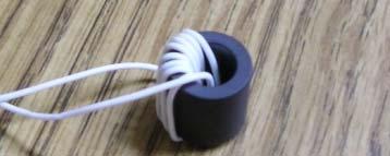
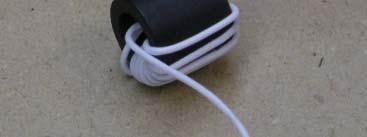
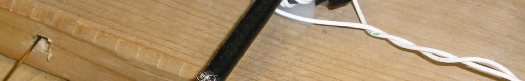
2 L. Thomson, B. Jones, J. Stephenson, C. Furse, Non-Contact Connections for Reflectometry and Location of Faults in Cable Shields, 2012 Aircraft Airworthiness and Sustainability Conference, April 2-5, 2012, Baltimore, MD Locating Small Apertures in Cable Shielding Lucas Thomson*(1), Brian Jones(1), and Cynthia Furse(1),(2) (1) University of Utah, Salt Lake City, UT, (2) Livewire Innovation This paper addresses the propagation of a signal through a small aperture in cable shielding. This may enable the location of holes (faults) in shielded cables using reflectometry. Reflectometry is an effective method for locating hard faults, such as an open or short, in transmission lines. However if the fault is small, such as a partial break in cable shielding, current methods are not capable of detecting and locating the fault. The impedance change due to the small breaks in shielding are so small that environmental variation masks them. As an alternative, this paper evaluates a novel method of using the transmitted field through the hole and ti d th l th f th bl t l t th f lt i th hi ld propagating down the length of the cable to locate the fault in the shield. The premise of this work is that when a break in cable shielding occurs, the signal that was exclusively internal to the cable now exists on the outside of the cable and can be used to locate the fault. This paper includes simulations of the fields that escape the hole. These results are compared to those of an analytical model for small faults: (R E Collin Foundations for Microwave Engineering IEEE for small faults: (R.E Collin, Foundations for Microwave Engineering, IEEE Press Series on Electromagnetic Wave Theory, 2nd edition, John Wiley and Sons, 2000). Next, both simulated and measured results are given for the fields propagating on the outside of the cable. The velocity of propagation and polarization are evaluated. Once the signal is propagating along the exterior of the cable there are various methods for detecting it In this paper a ferrite loaded cable, there are various methods for detecting it. In this paper, a ferrite loaded toroid sensor as shown in Figure 1 is used to receive the external magnetic fields. The design of the sensor will be discussed from its analytical model to an analysis of measured and simulated data.
3 Aging and Damaged Infrastructure
4 Reflectometry Incident Pulse sent down wire Reflected Pulse comes back Time delay Time delay between Incident and Reflected Pulses tells distance to fault.
5 TDR: Time Common Reflectometry Methods FDR: Frequency STDR: Sequence SSTDR: Spread Spectrum
6 Finding Hard Faults Unspecified Failure 6% Short due to corrosion 1% Short circuit unspecified cause (includes arcing incidents) 3% Loose connection 2% Insulation failure 3% Failure due to corrosion 7% Miswire 8% Chafed wire insulation leading to short circuit and/or arcing 32% Other Connector Failure Broken Wires 10% 19% 9% 18% Data: D. Lee and P. Arnason, U.S. Navy Wiring Systems Lessons Learned, Presentation at the Joint Conference on Aging Aircraft, 2000.

7 TDR Fault Response Hard Fault L. A. Griffiths, R. Parakh, C. Furse, B. Baker, The Invisible Fray: A Critical Analysis of the Use of Reflectometry for Fray Location, IEEE Sensors J., vol. 6, no. 3, pp , Jun
8 Hard Fault Open Circuit Γ= +1 (Hard Fault)
9 Finding Soft Faults Unspecified Failure 6% Short due to corrosion 1% Short circuit unspecified cause (includes arcing incidents) 3% Loose connection 2% Insulation failure 3% Failure due to corrosion 7% Miswire 8% Chafed wire insulation leading to short circuit and/or arcing 32% Other Connector Failure Broken Wires 10% 19% 9% 18% Data: D. Lee and P. Arnason, U.S. Navy Wiring Systems Lessons Learned, Presentation at the Joint Conference on Aging Aircraft, 2000.
10 Chafe/Fray A common method of fault location is reflectometry, however this method is not able to detect the very small reflections from shield damage. For small faults the initial reflected signal will be cancelled out by the secondary reflected signal L. A. Griffiths, R. Parakh, C. Furse, B. Baker, The Invisible Fray: A Critical Analysis of the Use of Reflectometry for Fray Location, IEEE Sensors J., vol. 6, no. 3, pp , Jun
11 TDR Fault Response Hard Fault Chafes L. A. Griffiths, R. Parakh, C. Furse, B. Baker, The Invisible Fray: A Critical Analysis of the Use of Reflectometry for Fray Location, IEEE Sensors J., vol. 6, no. 3, pp , Jun
12 Soft Fault Z << Zo (Soft Fault)
13 TDR Fault Response Movement Noise Hard Fault Chafes L. A. Griffiths, R. Parakh, C. Furse, B. Baker, The Invisible Fray: A Critical Analysis of the Use of Reflectometry for Fray Location, IEEE Sensors J., vol. 6, no. 3, pp , Jun
14 Soft Fault w/ Noise Z << Zo (Soft Fault)


15 Faulty Shield on Coaxial Cable Undamaged Cable Exposed Shield Faulty Shield
16 Coax no impedance change from environmental changes Movement Noise Hard Fault Chafes L. A. Griffiths, R. Parakh, C. Furse, B. Baker, The Invisible Fray: A Critical Analysis of the Use of Reflectometry for Fray Location, IEEE Sensors J., vol. 6, no. 3, pp , Jun
17 TDR Requires Large Dynamic Range Hard Fault Chafes L. A. Griffiths, R. Parakh, C. Furse, B. Baker, The Invisible Fray: A Critical Analysis of the Use of Reflectometry for Fray Location, IEEE Sensors J., vol. 6, no. 3, pp , Jun


: 2.")
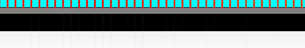
18 εr~2.4 A different method: Fields Contained Quasi TEM ZERO fields leak from to outside Electric Field Radius (mm): Magnetic Field εr~3.5 PEC


..")


19 E-Fields From Fault Fringing g Fields (non- zero!).. Smaller dynamic Range TM Modes Only (Surface Wave)
20 Receiver Choices - Capacitive E Field


21 Receiver Choices - Inductive H Field H Field


22 Toroid Sensor for Detection of External Fields


23 Why Does It Work? Coax is shielded. NO SSTDR signal from inside should be outside. ANY SSTDR signal is from the hole. We can receive the signal, detect the hole, locate the hole.


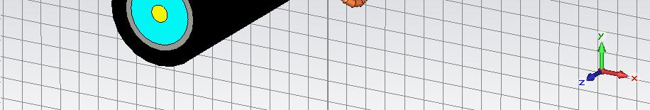
24 Incident Excitation E&H Fields Inside Cable
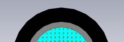
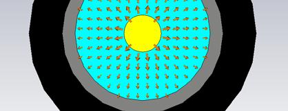
25 Internal E&H Fields Leak Out of Hole (HP Filter Hole = HP Filter (Current is derivative of Incident Signal)


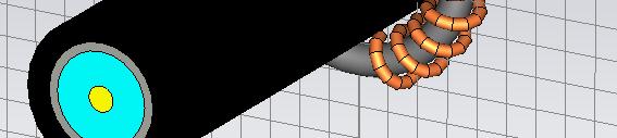
26 Leaky (H) Fields Produce Surface Current Line is LP Filter (Current is attenuated)
 Ferromagnetic core acts like a flux concentrator")
27 Surface Current Produces Magnetic Field In Ferrite Ferrite = LP Filter (depends on material) Ferromagnetic core acts like a flux concentrator


28 Magnetic Field In Ferrite Produces Current in Coil
 Nturns = Higher")
29 Current in Coil produces Vemf Vemf Toroid = HP Filter (Vemf ~ db/dt) Nturns = Higher Vemf


30 E-Field 4mm 3mm 2mm 1mm E Field is a copy of the original signal, decreasing away from the center conductor
")

31 E-Field 1mm 6mm Evanescent Near Fields (copy of original signal) Propagating Far Fields (derivative of original signal / high pass filtered)

32 Fault Effects 3mm Wide Fault

33 Fault Effects 10mm Long 10mm Long Fault
34 Vemf : Received Sensor Signal Hole = HP Filter (Current is HP Version of Incident Signal) Cable Line is LP Filter (Current is attenuated) Ferrite = LP Filter (depends on material) Sensor Toroid = HP Filter (Vemf ~ db/dt)


35 Pulse Shape Input Gaussian Pulse Circular shield fault Circular shield fault of radius 1mm


36 Velocity of Propagation - Numerical 25mm mm CST Simulation VOP ~ 0.94c (c =speed of light) Numerical Parameter Extraction VOP ~ 0.935c Zo ~ 396 Ω
37 Velocity of Propagation - measured Simulation: VOP ~ 0.94c (c =speed of light) Measured: 1 st Order Fit ~ 0.92c Median ( ) ~ c
38 Measurement Setup Network Analyzer Port 2 Port 1 HP 8753C X 10 ft 30 ft RG58 cable
39 Measurement Results Baseline measurement at 10ft 1cm damage at 10ft mark 13.5 feet *.94c /.66c /2 = 9.61 feet
40 Characterization of Sensor Characterize Parameters Windings Wire Gauge Geometry Materials Maximize Induced emf Signal Generator trise=1ns 6 AWG Digital Oscilloscope


41 Sensor Geometry Effective Magnetic Length Cross Sectional Area OD ID

42 Characterization: Number of Windings
43 Characterization: Winding Wire Gauge

44 Characterization: Geometry Effective Magnetic Length OD ID

45 Characterization: Geometry Cross Sectional Area
46 Characterization: Materials
47 Characterization: Materials


48 Sensor Characterization Windings Keep Low Wire Gauge Larger than 30AWG Geometry Increase Area Minimize Magnetic Length Materials N40 (Least Dispersion at 200 MHz)
49 Preliminary Measurements RG58 Coaxial Cable C B E A D F Open Ended A B C D E F Over Fault Offset Off Fault 75mm 150mm 300mm Signal Generator
50 10mm Fault


51 Fault Detection (5 mm) ~5mm Fault
 Fault")
52 Fault Localization (5 mm Fault) Fault
")
53 Fault Localization (15 mm Fault) Fault

54 Goals Need to localize and characterize apertures in coaxial shielding Traditional reflectometry not suited for shield apertures Accomplished with an external inductive noncontact sensor


55 Lucas Thomson University of Utah
56 All rights reserved. No part of this presentation may be copied or reused without express written permission of the authors. Contact: Dr. Cynthia Furse
Fault Location on Branched Wire Networks
 Fault Location on Branched Wire Networks Dr. Chet Lo*, Kedarnath Nagoti*, Dr. You Chung Chung**, Dr. Cynthia Furse*,*** *, Center of Excellence for Smart Sensors LiveWire Test Labs, Inc.*** Salt Lake City,
Partial Disconnected Cable Fault Detection Using Improved SSTDR
 , pp.113-117 http://dx.doi.org/10.14257/astl.2016.141.23 Partial Disconnected Cable Fault Detection Using Improved SSTDR Ga-Ram Han 1, Jeong-Chay Jeon 1, Jae-Jin Kim 1 and Myeong-Il Choi 1 1 Korea Electrical
IN AN aging aircraft, the condition of the wires and cables
 812 IEEE SENSORS JOURNAL, VOL 6, NO 3, JUNE 2006 Multicarrier Reflectometry Suketu Naik, Cynthia M Furse, Senior Member, IEEE, and Behrouz Farhang-Boroujeny, Senior Member, IEEE Abstract A new reflectometry
AGING electrical wiring systems have been identified as
 IEEE SENSORS JOURNAL, VOL. 7, NO. 1, JANUARY 2007 43 Low-Power STDR CMOS Sensor for Locating Faults in Aging Aircraft Wiring Chirag R. Sharma, Student Member, IEEE, Cynthia Furse, Senior Member, IEEE,
FEASIBILITY OF REFLECTOMETRY FOR NON-DESTRUCTIVE EVALUATION OF PRESTRESSED CONCRETE ANCHORS
 FEASIBILITY OF REFLECTOMETRY FOR NON-DESTRUCTIVE EVALUATION OF PRESTRESSED CONCRETE ANCHORS Dr. Cynthia Furse*,**, Dr. Paul Smith**, Michael Diamond** *University of Utah **LiveWire Test Labs, Inc. Salt
Transmission Lines and TDR
 Transmission Lines and TDR Overview This is the procedure for lab 2a. This is a one-week lab. The prelab should be done BEFORE going to the lab session. In this lab, the characteristics of different transmission
Enhanced Locating Method for Cable Fault Using Wiener Filter
 Universal Journal of Electrical and Electronic Engineering 3(4): 107-111, 2015 DOI: 10.13189/ujeee.2015.030401 http://www.hrpub.org Enhanced Locating Method for Cable Fault Using Wiener Filter Jeong Jae
Transmission Line Signal Sampling By Don Steinbach, AE6PM
 Transmission Line Signal Sampling By Don Steinbach, AE6PM When I was finalizing the mechanical layout of my remotely-operated 3-position coaxial antenna switch (Fig. 1), I wanted to include a way to bring
Keysight Technologies Techniques for Advanced Cable Testing
 Keysight Technologies Techniques for Advanced Cable Testing Using FieldFox handheld analyzers Application Note Transmission lines are used to guide the flow of energy from one point to another. Line types
Microwave and optical systems Introduction p. 1 Characteristics of waves p. 1 The electromagnetic spectrum p. 3 History and uses of microwaves and
 Microwave and optical systems Introduction p. 1 Characteristics of waves p. 1 The electromagnetic spectrum p. 3 History and uses of microwaves and optics p. 4 Communication systems p. 6 Radar systems p.
FOR MANY years, wiring has been treated as a system that
 IEEE SENSORS JOURNAL, VOL. 5, NO. 6, DECEMBER 2005 1469 Analysis of Spread Spectrum Time Domain Reflectometry for Wire Fault Location Paul Smith, Member, IEEE, Cynthia Furse, Senior Member, IEEE, and Jacob
Measurement Notes. Note 61. November Windscreen Shield Monitoring Using a Spiral Transmission Line
 Measurement Notes Note 61 November 28 Windscreen Shield Monitoring Using a Spiral Transmission Line Everett G. Farr. W. Scott Bigelow, and Leland H. Bowen Farr Research, Inc. Carl E Baum University of
A Reflectometer for Cable Fault Location with Multiple Pulse Reflection Method
 2014 by IFSA Publishing, S. L. http://www.sensorsportal.com A Reflectometer for Cable Fault Location with Multiple Pulse Reflection Method Zheng Gongming Electronics & Information School, Yangtze University,
Design and experimental realization of the chirped microstrip line
 Chapter 4 Design and experimental realization of the chirped microstrip line 4.1. Introduction In chapter 2 it has been shown that by using a microstrip line, uniform insertion losses A 0 (ω) and linear
Real-time Diagnosis of Wire Degradation based on Digital Signal Analysis
 2017 IEEE 67th Electronic Components and Technology Conference Real-time Diagnosis of Wire Degradation based on Digital Signal Analysis Jinwoo Lee, Daeil Kwon System Design and Control Engineering UNIST
2/18/ Transmission Lines and Waveguides 1/3. and Waveguides. Transmission Line A two conductor structure that can support a TEM wave.
 2/18/2009 3 Transmission Lines and Waveguides 1/3 Chapter 3 Transmission Lines and Waveguides First, some definitions: Transmission Line A two conductor structure that can support a TEM wave. Waveguide
Γ L = Γ S =
 TOPIC: Microwave Circuits Q.1 Determine the S parameters of two port network consisting of a series resistance R terminated at its input and output ports by the characteristic impedance Zo. Q.2 Input matching
Waveguides. Metal Waveguides. Dielectric Waveguides
 Waveguides Waveguides, like transmission lines, are structures used to guide electromagnetic waves from point to point. However, the fundamental characteristics of waveguide and transmission line waves
Pulse Arrested Spark Discharge (PASD) Wiring Diagnostic**
 Wiring Diagnostic**") 8 th Joint FAA/DoD/NASA Conference on Aging Aircraft February, 5 Pulse Arrested Spark Discharge (PASD) Wiring Diagnostic** Larry X Schneider *, M. Dinallo, R. K. Howard, S. F. Glover, G. E. Pena **, T.
8 th Joint FAA/DoD/NASA Conference on Aging Aircraft February, 5 Pulse Arrested Spark Discharge (PASD) Wiring Diagnostic** Larry X Schneider *, M. Dinallo, R. K. Howard, S. F. Glover, G. E. Pena **, T.
Alternative Coupling Method for Immunity Testing of Power Grid Protection Equipment
 Alternative Coupling Method for Immunity Testing of Power Grid Protection Equipment Christian Suttner*, Stefan Tenbohlen Institute of Power Transmission and High Voltage Technology (IEH), University of
APPLIED ELECTROMAGNETICS: EARLY TRANSMISSION LINES APPROACH
 APPLIED ELECTROMAGNETICS: EARLY TRANSMISSION LINES APPROACH STUART M. WENTWORTH Auburn University IICENTBN Nlfll 1807; WILEY 2 OO 7 ; Ttt^TlLtftiTTu CONTENTS CHAPTER1 Introduction 1 1.1 1.2 1.3 1.4 1.5
OPEN SOURCE CABLE MODELS FOR EMI SIMULATIONS
 OPEN SOURCE CABLE MODELS FOR EMI SIMULATIONS S. Greedy 1, C. Smartt 1, D. W. P. Thomas 1. 1 : George Green Institute for Electromagnetics Research, Department of Electrical and Electronic Engineering,
Transmission Line Theory and Advanced Measurements in the Field
 Transmission Line Theory and Advanced Measurements in the Field Co-sponsored by Tom Hoppin Application Specialist On Contract to Component Test Division Keysight Technologies Keysight Technologies 2015
MAINTENANCE of aging wiring is a significant challenge
 IEEE SENSORS JOURNAL, VOL. 5, NO. 6, DECEMBER 2005 1445 Feasibility of Spread Spectrum Sensors for Location of Arcs on Live Wires Cynthia Furse, Senior Member, IEEE, Paul Smith, Member, IEEE, Mehdi Safavi,
Lab 1: Pulse Propagation and Dispersion
 ab 1: Pulse Propagation and Dispersion NAME NAME NAME Introduction: In this experiment you will observe reflection and transmission of incident pulses as they propagate down a coaxial transmission line
Bill Ham Martin Ogbuokiri. This clause specifies the electrical performance requirements for shielded and unshielded cables.
 098-219r2 Prepared by: Ed Armstrong Zane Daggett Bill Ham Martin Ogbuokiri Date: 07-24-98 Revised: 09-29-98 Revised again: 10-14-98 Revised again: 12-2-98 Revised again: 01-18-99 1. REQUIREMENTS FOR SPI-3
EFFECT OF SHIELDING ON CABLE RF INGRESS MEASUREMENTS LARRY COHEN
 EFFECT OF SHIELDING ON CABLE RF INGRESS MEASUREMENTS LARRY COHEN OVERVIEW Purpose: Examine the common-mode and differential RF ingress levels of 4-pair UTP, F/UTP, and F/FTP cables at an (RJ45) MDI port
MAGNETO-DIELECTRIC COMPOSITES WITH FREQUENCY SELECTIVE SURFACE LAYERS
 MAGNETO-DIELECTRIC COMPOSITES WITH FREQUENCY SELECTIVE SURFACE LAYERS M. Hawley 1, S. Farhat 1, B. Shanker 2, L. Kempel 2 1 Dept. of Chemical Engineering and Materials Science, Michigan State University;
Transmission Lines and TDR
 Transmission Lines and TDR Overview This is the procedure for lab 2b. This is a one- week lab. The prelab should be done BEFORE going to the lab session. In this lab, pulse propagation down transmission
Telecommunication Wiring Questions
 Telecommunication Wiring Questions 1. is the process of modifying a carrier frequency in rhythm to the audio frequency. A, Modulation B. Amplitude C. Change of phase D. Interference 2. is the property
P a g e 1 ST985. TDR Cable Analyzer Instruction Manual. Analog Arts Inc.
 P a g e 1 ST985 TDR Cable Analyzer Instruction Manual Analog Arts Inc. www.analogarts.com P a g e 2 Contents Software Installation... 4 Specifications... 4 Handling Precautions... 4 Operation Instruction...
A short, off-center fed dipole for 40 m and 20 m by Daniel Marks, KW4TI
 A short, off-center fed dipole for 40 m and 20 m by Daniel Marks, KW4TI Version 2017-Nov-7 Abstract: This antenna is a 20 to 25 foot long (6.0 m to 7.6 m) off-center fed dipole antenna for the 20 m and
ELECTROMAGNETIC COMPATIBILITY HANDBOOK 1. Chapter 8: Cable Modeling
 ELECTROMAGNETIC COMPATIBILITY HANDBOOK 1 Chapter 8: Cable Modeling Related to the topic in section 8.14, sometimes when an RF transmitter is connected to an unbalanced antenna fed against earth ground
Internal Model of X2Y Chip Technology
 Internal Model of X2Y Chip Technology Summary At high frequencies, traditional discrete components are significantly limited in performance by their parasitics, which are inherent in the design. For example,
Transformers. Objectives
 Transformers Objectives Explain mutual inductance Describe how a transformer is constructed and how it works Explain how a step-up transformer works Explain how a step-down transformer works Discuss the
ARNSW Balun Day. Balun construction
 ARNSW Balun Day Balun construction Typical Baluns All built from locally available components. Balun uses Most baluns are used to match the 50Ω output of a transceiver to an antenna. A centre fed dipole
Chapter 12: Transmission Lines. EET-223: RF Communication Circuits Walter Lara
 Chapter 12: Transmission Lines EET-223: RF Communication Circuits Walter Lara Introduction A transmission line can be defined as the conductive connections between system elements that carry signal power.
RTD-6M PD SENSOR BOARD
 RTD6M PD SENSOR BOARD INSTALLATION MANUAL IB07005E Rev.B September 0 PREDICTIVE DIAGNOSTICS 5 Feltl Road, Ste 90, Minnetonka, MN 55, USA Phone (95) 9, Fax (95) 955; Website: www.eaton.com\pd Email: chpd@eaton.com
The DC Isolated 1:1 Guanella Transmission Line Transformer
 The DC Isolated 1:1 Guanella Transmission Line Transformer by Chris Trask / N7ZWY Sonoran Radio Research P.O. Box 25240 Tempe, AZ 85285-5240 Email: christrask@earthlink.net Expanded and Revised 14 August
K1200 Stripper Foil Mechanism RF Shielding
 R.F. Note #121 Sept. 21, 2000 John Vincent Shelly Alfredson John Bonofiglio John Brandon Dan Pedtke Guenter Stork K1200 Stripper Foil Mechanism RF Shielding INTRODUCTION... 2 MEASUREMENT TECHNIQUES AND
ASIC Implementation of Live Arc Fault SSTDR Tester
 ASIC Implementation of Live Arc Fault SSTDR Tester Dr. Paul Smith 1, psmith@livewiretest.com, LiveWire Test Labs Dr. Paul Kuhn 1, pkuhn@livewiretest.com, LiveWire Test Labs Michael Diamond 1, mdiamond@livewiretest.com,
Current Probes. User Manual
 Current Probes User Manual ETS-Lindgren Inc. reserves the right to make changes to any product described herein in order to improve function, design, or for any other reason. Nothing contained herein shall
Amateur Extra Manual Chapter 9.4 Transmission Lines
 9.4 TRANSMISSION LINES (page 9-31) WAVELENGTH IN A FEED LINE (page 9-31) VELOCITY OF PROPAGATION (page 9-32) Speed of Wave in a Transmission Line VF = Velocity Factor = Speed of Light in a Vacuum Question
TileCal Analogue Cable Measurement Report
 Weiming Qian w.qian@rl.ac.uk +44-1235-446128 Rutherford Appleton Laboratory, UK 25 August 2005 Contents Contents... 2 1 Scope... 3 2 Impedance measurements... 3 2.1 Test setup... 3 2.2 Differential mode
Development of a noval Switched Beam Antenna for Communications
 Master Thesis Presentation Development of a noval Switched Beam Antenna for Communications By Ashraf Abuelhaija Supervised by Prof. Dr.-Ing. Klaus Solbach Institute of Microwave and RF Technology Department
USE OF MICROWAVES FOR THE DETECTION OF CORROSION UNDER INSULATION
 USE OF MICROWAVES FOR THE DETECTION OF CORROSION UNDER INSULATION R. E. JONES, F. SIMONETTI, M. J. S. LOWE, IMPERIAL COLLEGE, London, UK I. P. BRADLEY, BP Exploration and Production Company, Sunbury on
Design of Microstrip Coupled Line Bandpass Filter Using Synthesis Technique
 Design of Microstrip Coupled Line Bandpass Filter Using Synthesis Technique 1 P.Priyanka, 2 Dr.S.Maheswari, 1 PG Student, 2 Professor, Department of Electronics and Communication Engineering Panimalar
University of Pennsylvania Department of Electrical and Systems Engineering ESE319
 University of Pennsylvania Department of Electrical and Systems Engineering ESE39 Laboratory Experiment Parasitic Capacitance and Oscilloscope Loading This lab is designed to familiarize you with some
Experiment No. 6 Pre-Lab Transmission Lines and Time Domain Reflectometry
 Experiment No. 6 Pre-Lab Transmission Lines and Time Domain Reflectometry The Pre-Labs are informational and although they follow the procedures in the experiment, they are to be completed outside of the
REQUIRED SKILLS AND KNOWLEDGE UEENEEG101A. Electromagnetic devices and circuits. Topic and Description NIDA Lesson CARD # Magnetism encompassing:
 REQUIRED SKILLS AND KNOWLEDGE UEENEEG101A KS01-EG101A Electromagnetic devices and circuits T1 Magnetism encompassing: Topic and Description NIDA Lesson CARD # magnetic field pattern of bar and horse-shoe
WHY YOU NEED A CURRENT BALUN
 HF OPERATORS WHY YOU NEED A CURRENT BALUN by John White VA7JW NSARC HF Operators 1 What is a Balun? A BALUN is a device typically inserted at the feed point of a dipole-like antenna wire dipoles, Yagi
Magnetics Design. Specification, Performance and Economics
 Magnetics Design Specification, Performance and Economics W H I T E P A P E R MAGNETICS DESIGN SPECIFICATION, PERFORMANCE AND ECONOMICS By Paul Castillo Applications Engineer Datatronics Introduction The
Chapter Moving Charges and Magnetism
 100 Chapter Moving Charges and Magnetism 1. The power factor of an AC circuit having resistance (R) and inductance (L) connected in series and an angular velocity ω is [2013] 2. [2002] zero RvB vbl/r vbl
High resolution LFMCW radar system using modelbased beat frequency estimation in cable fault localization
 LETTER IEICE Electronics Express, Vol.11, No.1, 1 6 High resolution LFMCW radar system using modelbased beat frequency estimation in cable fault localization Chun Ku Lee 1, Jin Bae Park 1a), Yong-June
THE PROPAGATION OF PARTIAL DISCHARGE PULSES IN A HIGH VOLTAGE CABLE
 THE PROPAGATION OF PARTIAL DISCHARGE PULSES IN A HIGH VOLTAGE CABLE Z.Liu, B.T.Phung, T.R.Blackburn and R.E.James School of Electrical Engineering and Telecommuniications University of New South Wales
12/6/2011. Electromagnetic Induction. Electromagnetic Induction and Electromagnetic Waves. Checking Understanding. Magnetic Flux. Lenz s Law.
 Electromagnetic Induction and Electromagnetic Waves Topics: Electromagnetic induction Lenz s law Faraday s law The nature of electromagnetic waves The spectrum of electromagnetic waves Electromagnetic
Table of Contents. Table of Figures. Table of Tables
 Abstract The aim of this report is to investigate and test a transformer and check if it is good to use by doing the following tests continuity test, insulation test, polarity test, open circuit test,
High Speed Competitive Comparison Report. Samtec MMCX-J-P-H-ST-TH1 Mated With MMCX-P-P-H-ST-TH1 Competitor A (Mated Set) Competitor B (Mated Set)
 Competitor B (Mated Set)") High Speed Competitive Comparison Report Samtec MMCX-J-P-H-ST-TH1 Mated With MMCX-P-P-H-ST-TH1 Competitor A (Mated Set) Competitor B (Mated Set) REVISION DATE: January 6, 2005 TABLE OF CONTENTS Introduction...
High Speed Competitive Comparison Report Samtec MMCX-J-P-H-ST-TH1 Mated With MMCX-P-P-H-ST-TH1 Competitor A (Mated Set) Competitor B (Mated Set) REVISION DATE: January 6, 2005 TABLE OF CONTENTS Introduction...
A Dual-Polarized MIMO Antenna with EBG for 5.8 GHz WLAN Application
 Progress In Electromagnetics Research Letters, Vol. 51, 15 2, 215 A Dual-Polarized MIMO Antenna with EBG for 5.8 GHz WLAN Application Xiaoyan Zhang 1, 2, *, Xinxing Zhong 1,BinchengLi 3, and Yiqiang Yu
Pulse Transmission and Cable Properties ================================
 PHYS 4211 Fall 2005 Last edit: October 2, 2006 T.E. Coan Pulse Transmission and Cable Properties ================================ GOAL To understand how voltage and current pulses are transmitted along
Application Note # 5438
 Application Note # 5438 Electrical Noise in Motion Control Circuits 1. Origins of Electrical Noise Electrical noise appears in an electrical circuit through one of four routes: a. Impedance (Ground Loop)
Signal and Noise Measurement Techniques Using Magnetic Field Probes
 Signal and Noise Measurement Techniques Using Magnetic Field Probes Abstract: Magnetic loops have long been used by EMC personnel to sniff out sources of emissions in circuits and equipment. Additional
Strathprints Institutional Repository
 Strathprints Institutional Repository Given, M and Mason, Ronald and Judd, Martin and Mcglone, Phillip and Timoshkin, Igor and Wilson, Mark () Comparison between RF and electrical signals from the partial
High Speed Characterization Report
 High Speed Characterization Report MMCX-P-P-H-ST-TH1 mated with MMCX-J-P-H-ST-TH1 MMCX-P-P-H-ST-MT1 mated with MMCX-J-P-H-ST-MT1 MMCX-P-P-H-ST-SM1 mated with MMCX-J-P-H-ST-SM1 MMCX-P-P-H-ST-EM1 mated with
Technician License. Course
 Technician License Course Technician License Course Chapter 4 Lesson Plan Module - 9 Antenna Fundamentals Feed Lines & SWR The Antenna System The Antenna System Antenna: Transforms current into radio waves
Single-turn and multi-turn coil domains in 3D COMSOL. All rights reserved.
 Single-turn and multi-turn coil domains in 3D 2012 COMSOL. All rights reserved. Introduction This tutorial shows how to use the Single-Turn Coil Domain and Multi-Turn Coil Domain features in COMSOL s Magnetic
Shielding Effectiveness Report HQDP
 HQDP Mates with QSH-DP, QTH-DP Description: 0.50mm 100Ω Differential 30 AWG Twinax Cable Assembly Samtec, Inc. 2005 All Rights Reserved Table of Contents Product Overview... 1 Test Overview... 1 Shielded
Review 6. unlike poles cause the magnets to attract. like poles cause the magnets to repel.
 Review 6 1. The two characteristics of all magnets are: they attract and hold Iron, and, if free to move, they will assume roughly a south - north position. 2. Lines of flux always leave the north pole
A Few (Technical) Things You Need To Know About Using Ethernet Cable for Portable Audio
 Things You Need To Know About Using Ethernet Cable for Portable Audio") A Few (Technical) Things You Need To Know About Using Ethernet Cable for Portable Audio Rick Rodriguez June 1, 2013 Digital Audio Data Transmission over Twisted-Pair This paper was written to introduce
A Few (Technical) Things You Need To Know About Using Ethernet Cable for Portable Audio Rick Rodriguez June 1, 2013 Digital Audio Data Transmission over Twisted-Pair This paper was written to introduce
Sensor and Simulation Notes Note 565 June Improved Feed Design for Enhance Performance of Reflector Based Impulse Radiating Antennas
 1 Sensor and Simulation Notes Note 565 June 2013 Improved Feed Design for Enhance Performance of Reflector Based Impulse Radiating Antennas Dhiraj K. Singh 1, D. C. Pande 1, and A. Bhattacharya 2, Member,
A Simple Wideband Transmission Line Model
 A Simple Wideband Transmission Line Model Prepared by F. M. Tesche Holcombe Dept. of Electrical and Computer Engineering College of Engineering & Science 337 Fluor Daniel Building Box 34915 Clemson, SC
Overview of Grounding for Industrial and Commercial Power Systems Presented By Robert Schuerger, P.E.
 Overview of Grounding for Industrial and Commercial Power Systems Presented By Robert Schuerger, P.E. HP Critical Facility Services delivered by EYP MCF What is VOLTAGE? Difference of Electric Potential
Chokes and Isolation Transformers For Receiving Antennas By Jim Brown K9YC 2018 by James W. Brown All rights reserved
 Chokes and Isolation Transformers For Receiving Antennas By Jim Brown K9YC 2018 by James W. Brown All rights reserved Why We Need Them A feedline must be grounded where it enters the shack-for lightning
High Data Rate Characterization Report
 High Data Rate Characterization Report VPSTP-016-1000-01 Mated with: VRDPC-50-01-M-RA and VRDPC-50-01-M-RA Description: Plug Shielded Twisted Pair Cable Assembly, 0.8mm Pitch Samtec, Inc. 2005 All Rights
A New Method for the Calibration of the mv Ranges of an AC Measurement Standard
 A New Method for the Calibration of the mv Ranges of an AC Measurement Standard Speaker/Author Neil Faulkner Fluke Corporation PO Box 9090, Everett, WA 98206 Phone: (425) 446-5538 FAX: (425) 446-5649 E-mail:
Chapter 5 Electromagnetic interference in flash lamp pumped laser systems
 Chapter 5 Electromagnetic interference in flash lamp pumped laser systems This chapter presents the analysis and measurements of radiated near and far fields, and conducted emissions due to interconnects
EMG4066:Antennas and Propagation Exp 1:ANTENNAS MMU:FOE. To study the radiation pattern characteristics of various types of antennas.
 OBJECTIVES To study the radiation pattern characteristics of various types of antennas. APPARATUS Microwave Source Rotating Antenna Platform Measurement Interface Transmitting Horn Antenna Dipole and Yagi
Surge Protection and Grounding Issues
 Surge Protection and Grounding Issues Presented to SCTE Chicago Chapter January 21, 2004 By: Nisar Chaudhry VP Electrical Engineering, CTO Introduction Transients caused by disturbances on the power lines
54100A Series. Distance-To-Fault
 54100A Series Distance-To-Fault Application Note Antenna/Transmission Line Installation and Maintenance. How To Control Costs and Maximize Reliability Using Frequency Domain Reflectometry Introduction
Transfer Functions in EMC Shielding Design
 Transfer Functions in EMC Shielding Design Transfer Functions Definition Overview of Theory Shielding Effectiveness Definition & Test Anomalies George Kunkel CEO, Spira Manufacturing Corporation www.spira-emi.com
Microwave Engineering
 Microwave Circuits 1 Microwave Engineering 1. Microwave: 300MHz ~ 300 GHz, 1 m ~ 1mm. a. Not only apply in this frequency range. The real issue is wavelength. Historically, as early as WWII, this is the
TOPIC 2 WAVEGUIDE AND COMPONENTS
 TOPIC 2 WAVEGUIDE AND COMPONENTS COURSE LEARNING OUTCOME (CLO) CLO1 Explain clearly the generation of microwave, the effects of microwave radiation and the propagation of electromagnetic in a waveguide
Design of a Novel Compact Cup Feed for Parabolic Reflector Antennas
 Progress In Electromagnetics Research Letters, Vol. 64, 81 86, 2016 Design of a Novel Compact Cup Feed for Parabolic Reflector Antennas Amir Moallemizadeh 1,R.Saraf-Shirazi 2, and Mohammad Bod 2, * Abstract
Technology in Balance
 Technology in Balance A G1 G2 B Basic Structure Comparison Regular capacitors have two plates or electrodes surrounded by a dielectric material. There is capacitance between the two conductive plates within
DATA INTEGRATION MULTICARRIER REFLECTOMETRY SENSORS
 Report for ECE 4910 Senior Project Design DATA INTEGRATION IN MULTICARRIER REFLECTOMETRY SENSORS Prepared by Afshin Edrissi Date: Apr 7, 2006 1-1 ABSTRACT Afshin Edrissi (Cynthia Furse), Department of
Exercise 1-2. Velocity of Propagation EXERCISE OBJECTIVE
 Exercise 1-2 Velocity of Propagation EXERCISE OBJECTIVE Upon completion of this unit, you will know how to measure the velocity of propagation of a signal in a transmission line, using the step response
Instruction MI December Magnetic Flow System
 Instruction MI 021-138 December 2015 Magnetic Flow System 2800 Series Flowtubes with an 896 or an E96 Transmitter Fault Location Guide Contents Contents...3 Figures...5 Tables...6 Introduction...7 Reference
A Transmatch for Balanced or Unbalanced Lines
 A Transmatch for Balanced or Unbalanced Lines Most modern transmitters are designed to operate into loads of approximately 50 Ω. Solid-state transmitters produce progressively lower output power as the
Conduit measured transfer impedance and shielding effectiveness (typically achieved in the RS103 and CS114 tests)
") Conduit measured transfer impedance and shielding effectiveness (typically achieved in the RS3 and CS4 tests) D. A. Weston K. McDougall conduitse.doc 5-2-27 The data and information contained within this
Conduit measured transfer impedance and shielding effectiveness (typically achieved in the RS3 and CS4 tests) D. A. Weston K. McDougall conduitse.doc 5-2-27 The data and information contained within this
ECE2019 Sensors, Signals, and Systems A Lab #6: Electromagnetic Field Sensing
 ECE2019 Sensors, Signals, and Systems A 2012 Lab #6: Electromagnetic Field Sensing Introduction This lab involves construction of circuits which demonstrate electromagnetic properties of cables used in
Investigation of a Voltage Probe in Microstrip Technology
 Investigation of a Voltage Probe in Microstrip Technology (Specifically in 7-tesla MRI System) By : Mona ParsaMoghadam Supervisor : Prof. Dr. Ing- Klaus Solbach April 2015 Introduction - Thesis work scope
A New TEM Horn Antenna Designing Based on Plexiglass Antenna Cap
 Journal of Applied Science and Engineering, Vol. 21, No. 3, pp. 413 418 (2018) DOI: 10.6180/jase.201809_21(3).0012 A New TEM Horn Antenna Designing Based on Plexiglass Antenna Cap Lin Teng and Jie Liu*
AP Physics C. Alternating Current. Chapter Problems. Sources of Alternating EMF
 AP Physics C Alternating Current Chapter Problems Sources of Alternating EMF 1. A 10 cm diameter loop of wire is oriented perpendicular to a 2.5 T magnetic field. What is the magnetic flux through the
MEASUREMENTS OF COUPLING THROUGH BRAIDED SHIELD VIA NEW CONDUCTED IMMUNITY TECH- NIQUE
 Progress In Electromagnetics Research C, Vol. 11, 61 68, 2009 MEASUREMENTS OF COUPLING THROUGH BRAIDED SHIELD VIA NEW CONDUCTED IMMUNITY TECH- NIQUE M. Ghassempouri College of Electrical Engineering Iran
SECTION 3 BASIC AUTOMATIC CONTROLS UNIT 12 BASIC ELECTRICITY AND MAGNETISM. Unit Objectives. Unit Objectives 2/29/2012
 SECTION 3 BASIC AUTOMATIC CONTROLS UNIT 12 BASIC ELECTRICITY AND MAGNETISM Unit Objectives Describe the structure of an atom. Identify atoms with a positive charge and atoms with a negative charge. Explain
High Data Rate Characterization Report
 High Data Rate Characterization Report ERDP-013-39.37-TTR-STL-1-D Mated with: ERF8-013-05.0-S-DV-DL-L and ERM8-013-05.0-S-DV-DS-L Description: Edge Rate Twin-Ax Cable Assembly, 0.8mm Pitch Samtec, Inc.
Technician Licensing Class T9
 Technician Licensing Class T9 Amateur Radio Course Monroe EMS Building Monroe, Utah January 11/18, 2014 January 22, 2014 Testing Session Valid dates: July 1, 2010 June 30, 2014 Amateur Radio Technician
EC Transmission Lines And Waveguides
 EC6503 - Transmission Lines And Waveguides UNIT I - TRANSMISSION LINE THEORY A line of cascaded T sections & Transmission lines - General Solution, Physical Significance of the Equations 1. Define Characteristic
Design of Differential Protection Scheme Using Rogowski Coil
 2017 IJSRST Volume 3 Issue 2 Print ISSN: 2395-6011 Online ISSN: 2395-602X National Conference on Advances in Engineering and Applied Science (NCAEAS) 16 th February 2017 In association with International
Improved High-Frequency Planar Transformer for Line Level Control (LLC) Resonant Converters
 Resonant Converters") Improved High-Frequency Planar Transformer for Line Level Control (LLC) Resonant Converters Author Water, Wayne, Lu, Junwei Published 2013 Journal Title IEEE Magnetics Letters DOI https://doi.org/10.1109/lmag.2013.2284767
Improved High-Frequency Planar Transformer for Line Level Control (LLC) Resonant Converters Author Water, Wayne, Lu, Junwei Published 2013 Journal Title IEEE Magnetics Letters DOI https://doi.org/10.1109/lmag.2013.2284767