MC-3 Laser Marking Controller
|
|
|
- Cameron Tyler
- 6 years ago
- Views:
Transcription

1 MC- Laser Marking Controller User Manual Version /0/09
2 Contents MC CONNECTORS LAYOUT... D/A RECEIVER CONNECTORS LAYOUT... MC CONNECTOR PIN ASSIGNMENTS AND SIGNAL DESCRIPTIONS... JUMPER SETTINGS D/A RECEIVER CONNECTOR PIN ASSIGNMENTS AND SIGNAL DESCRIPTIONS... 1 MC1_B_MOTION BOARD USING RS-... CABLE WIRINGS...
3 MC Connectors layout P1 DAC board IF Port P AO/Laser Control Port 1 mm 1 mm P Program Status/ Ext Triggers Port P1 P P JP5 JP6 JP7 JP D1 D D D 115 mm 105 mm CN5 J7 CN LED1 LED LED LED LED5 LED6 LED7 LED8 P CN DSP Interface Port P USB Type-B Port JR1 + J1 CN1 CN JP8 CN SW1 Reset switch J1 5V DC-Jack CN1 16-bit Output port CN 16-bit Input Port CN Encoder Input
4 D/A receiver Connectors layout Offset Adj. Gain Adj. DA-X DA-Y Output Port Polarities 70 mm 60 mm CN8 CN9 JP8 VR VR1 CN7 External Power P5 MC IF Port CN10 6-I/-O Ports 8 mm 58 mm JP1 Output Pull-ups D1
5 MC Connector Pin Assignments and Signal Descriptions P1---D/A board interface port D/A board interface are a high-density D-SUB connector providing digital control signals to DAC board. Pin No. I/O Type Signal Name Description Comment 1 Power +1V +1V power to D/A I DSTATUS+ Status input from D/A O DATA_X+ Channel 1 data stream to D/A O DSYNC+ Synchronization signal to D/A 5 O DCLK+ Clock signal to D/A 6 Power/O -1V -1V power to D/A 7 I DSTATUS- Status input from D/A 8 O DATA_X- Channel 1 data stream to D/A 9 O DSYNC- Synchronization signal to D/A 10 O DCLK- Clock signal to D/A 11 Power Ground 1 Power Ground 1 Power 5V +5V power to D/A 1 Power Ground Short JP5.1 to JP5. 1 O DATA_Y+ Channel data stream to D/A Short JP5.5 to JP Power Ground Short JP5. to JP5. 1 O DATA_Y- Channel data stream to D/A Short JP5.6 to JP5. 1 Caution 1 The default settings are JP5.1 to JP5. and JP5. to JP5., i.e. Pin 1 and pin 15 serve as ground connections. When the controller is used to drive a XY-100 interface DA board, connect JP5.5 to JP5. and JP5.6 to JP5., i.e. P1 and pin 15 serve as Y channel connection. Under such case, P and pin 9 serve as X channel, and firmware setting should be adjusted accordingly. pin 1, close pin, close JP5
6 P---Analog Output/Laser Control port Analog Output/Laser Control port is a D-SUB female connector providing analog outputs and digital outputs to control laser power and frequency. Pin No. I/O Type Signal Name Description Comment 1 O AO1 DAC 1 output, 1 bit resolution 0 ~ 10 V Power Analog ground of AO1/AO signals Power Ground of LASER_ON,LASER_PWM, LASER_FPS and +5V supply O LASER_PWM Programmable pulse width signal ±ma driving capability 5 O LASER_ON Laser on/off gate signal ±ma driving capability 6 O AO DAC output, 1 bit resolution 0 ~ 10 V 7 Power Analog ground of AO1/AO signals 8 Power 5V +5V supply Limited under 500mA 9 O LASER_FPS First pulse suppression signal ±ma driving capability Laser control timing diagram (CO) Start Of Mark End Of Mark Mark Line Laser On Delay Laser Off Delay LASER_ON Stand-By Period Q-Switch Period Q-Switch Pulse Width LASER_PWM Stand-By Pulse Width 5
7 Laser control timing diagram (YAG1, YAG,YAG) Start Of Mark End Of Mark Mark Line Laser On Delay Laser Off Delay LASER_ON Q-Switch Period Q-Switch Pulse Width YAG1 LASER_PWM (Q-Switch) First Pulse Suppress Length [pwm delay time = 0] LASER_FPS (first pulse suppress) Q-Switch Period Q-Switch Pulse Width YAG LASER_PWM (Q-Switch) pwm delay time First Pulse Suppress Length [pwm delay time = FPS length] LASER_FPS (first pulse suppress) Q-Switch Period Q-Switch Pulse Width YAG LASER_PWM (Q-Switch) 10 us First Pulse Suppress Length [pwm delay time = 10 us] LASER_FPS (first pulse suppress) Q-Switch Period Q-Switch Pulse Width YAG LASER_PWM (Q-Switch) pwm delay time First Pulse Suppress Length LASER_FPS (first pulse suppress) 6
8 P---Program Status/External Triggers port Program Status/External Triggers port is a D-SUB male connector providing digital outputs and digital inputs to control program execution. Pin No. I/O Type Signal Name Description LED No. 1 O PGM_RDY+ Collector of PGM_RDY signal O PGM_RDY- Emitter of PGM_RDY signal D1 O MARK_BUSY+ Collector of MARK_BUSY signal O MARK_BUSY- Emitter of MARK_BUSY signal D 5 Power Ground 6 I EI_START_A Input of EI_START signal 7 I EI_START_B Input of EI_START signal D 8 I EI_STOP_A Input of EI_STOP signal 9 I EI_STOP_B Input of EI_STOP signal D The PGM_RDY and MARK_BUSY signal is updated with commands set_ready_io_states, and set_ready_io_states_list. P---USB port P is a USB device port of USB-B type connector providing connection to USB host. CN bit digital output port CN1 is a 16-bit digital port of 0-pin connector providing 16 bits outputs. The output value is updated with commands write_io_port, write_io_port_list, set_io_cond_list, and clear_io_cond_list. The output value can be Pin No. I/O Type Signal Name Description Comment 1 O PO0 Bit 0 of output value O PO1 Bit 1 of output value O PO Bit of output value O PO Bit of output value 5 O PO Bit of output value 6 O PO5 Bit 5 of output value 7 O PO6 Bit 6 of output value 8 O PO7 Bit 7 of output value 9 O PO8 Bit 8 of output value 10 O PO9 Bit 9 of output value 11 O PO10 Bit 10 of output value 1 O PO11 Bit 11 of output value 1 O PO1 Bit 1 of output value 1 O PO1 Bit 1 of output value 15 O PO1 Bit 1 of output value 7
9 16 O PO15 Bit 15 of output value 17 Power Ground 18 Power Ground 19 Power F_5V 5V supply protected by fuse Max. 100mA output current 0 N/C Not connected CN1 and CN provides 16 bit output and 16 bit input. Each output is able to source/sink up to ma. All output ports are initialized to low after power-up reset. CN---16-bit digital input port CN1 is a 16-bit digital port of 0-pin connector providing 16 bits inputs. The input value is sampled with commands read_io_port, get_io_status, list_jump_cond, and list_call_cond. Pin No. I/O Type Signal Name Description Comment 1 I PI0 Bit 0 of input value I PI1 Bit 1 of input value I PI Bit of input value I PI Bit of input value 5 I PI Bit of input value 6 I PI5 Bit 5 of input value 7 I PI6 Bit 6 of input value 8 I PI7 Bit 7 of input value 9 I PI8 Bit 8 of input value 10 I PI9 Bit 9 of input value 11 I PI10 Bit 10 of input value 1 I PI11 Bit 11 of input value 1 I PI1 Bit 1 of input value 1 I PI1 Bit 1 of input value 15 I PI1 Bit 1 of input value 16 I PI15 Bit 15 of input value 17 Power Ground 18 Power Ground 19 Power F_5V 5V supply protected by fuse Max. 100mA output current 0 N/C Not connected *Pins 1 to 16 are internally pulled-low with 7K resistors. CN---X/Y position encoder port
10 Support for mark_on_fly feature. Pin No. I/O Type Signal Name Description Comment 1 Power Ground Power Ground I X A+ Encoder X A+ I X A- Encoder X A- 5 I X B+ Encoder X B+ 6 I X B- Encoder X B- 7 I Y A+ Encoder Y A+ 8 I Y A- Encoder Y A- 9 I Y B+ Encoder Y B+ 10 I Y B- Encoder Y B- 11 Power Ground 1 Power Ground *The encoder inputs EncoderX and EncoderY are designed for a pair of standardized differential signals (RS-) each. CN---DSP interface port Interface port to on-board DSP, reserved for future expansion. 9
11 Jumper Settings The first pin of each pin header is marked with symbol AO1 / AO signal voltage range The voltage range can be programmed with the following jumper pins. Jumper Pin No. JP6 1 JP7 1 Status Open AO1 (0V 5V) Close AO1 (0V 10V) defalut Open AO (0V 5V) Close AO (0V 10V) defalut Description External Trigger Inputs External triggers signals can be programmed with following jumper pins. Jumper Pin No. JP 5 6 JP 7 8 Status Open Close Open Close Description EI_START is an isolated input. EI_START_B is pulled up. (default) EI_STOP is an isolated input. EI_STOP_B is pulled up. (default) Two LEDs, D and D, give visual indication of EI_START and EI_STOP signals to facilitate program/wiring debugging. 1N5817 5V P.6 EI_START_A (P.8 EI_STOP_A) 1 70R JP.6 (JP.8) JP.5 (JP.7) 10K nstart P.7 EI_START_B (P.9 EI_STOP_B) 1.5K 10
12 Program Status Outputs and LEDs Program Status output signals can be programmed with following jumper pins. Jumper Pin No. JP 1 JP Status Open Close Open Close Description PGM_RDY is an isolated input. (default) PGM_RDY+ is pulled up. MARK_BUSY is an isolated input. (default) MARK_BUSY+ is pulled up. Two LEDs, D1 and D, give visual indication of PGM_RDY and MARK_BUSY signals to facilitate program debugging. 1N5817 PGM_RDY (MARK_BUSY) 70 5V 70 1K JP. (JP.) D1 Red (D Orange) 1 LTV81S JP.1 (JP.) P.1 PGM_RDY+ (P. MARK_BUSY+) P. PGM_RDY- (P. MARK_BUSY-) Singal Polarity Settings (1) START signal () STOP signal () PGM_RGY signal () MARK_BUSY signal (5) LASER_ON signal (6) LASER_PWM signal (7) LASER_FPS signal these signals can be programmed with HWConfig_MC.exe. 11
13 System Status LED Outputs The System Status LEDs give visual indications of various system health status. LED No. Status Comment steady on X LED1 twinkling bootloader work mode steady off dsp program work mode steady on bootloader is running LED twinkling dsp program is running steady off X steady on list buffer is running LED twinkling X steady off wait for list buffer execution steady on execute Laser On command LED twinkling X steady off execute Laser Off command steady on MC Power On LED5 twinkling X steady off MC Power Off steady on PIC shutdowm LED6 twinkling PIC Running steady off PIC shutdowm steady on PIC communication error with DSP LED7 twinkling USB data transfer rate steady off USB no data transfer steady on USB communication breakdown LED8 twinkling X steady off USB connection MC Status LED1 LED LED LED LED5 LED6 LED7 LED8 Boot_loader program twinkling steady steady steady steady twinkling twinkling steady on on off on off DSP program steady off twinkling steady steady steady twinkling twinkling steady off off on off 1
14 Interfacing to XY-100 D/A board In this mode, MC is configured to driver a XY-100 compliant D/A board, which can be a foreign D/A board or a D/A receiver board in XY-100 Mode with proper DB5 converter. When MC is used to drive XY-100 interface, the following steps are necessary. 1. On JP5, short pin to pin 5, and short pin to pin 6.. Run HWConfig_MC.exe program to select XY-100 transfer protocol type.. Assembly the cable of High-Density DB-15 connector to DB5 connector as the following table. Pin, 6 close JP5 Pin, 5 close 15 pin DB15 to 5 pin DB5 (XY-100 TYPE) MC P1 ( DB15) Description XY-100 D/A (DB5) Pin Signal Signal Pin 1 +1V Not Connected DSTATUS+ Status input from D/A DSTATUS+ 19 DATA_X+ Channel 1 data stream CHANNEL1+ 16 DSYNC+ Synchronization signal to D/A DSYNC DCLK+ Clock signal to D/A DCLK V Not Connected 7 DSTATUS- Status input from D/A DSTATUS- 6 8 DATA_X- Channel 1 data stream CHANNEL1 9 DSYNC- Synchronization signal to D/A DSYNC 10 DCLK- Clock signal to D/A DCLK 1 11 Ground *** 1 Ground *** 1 5V Not Connected 1 DATA_Y+ Channel data stream CHANNEL DATA_Y- Channel data stream CHANNEL 1
15 D/A receiver Connector Pin Assignments and Signal Descriptions P5---Controller Interface port MC interface is a slim high-density D-SUB connector providing digital control signals to Marking Controller board. D/A receiver board may work in either XY-100 mode or proprietary mode according to factory settings. When D/A receiver is configured to XY-100 mode, any controllers with XY-100 interface nay drive D/A receiver board as long as the cable is properly assembled. Pin No. I/O Type Signal Name Description Comment 1 Power +1V +1V power from Controller O DSTATUS+ Status output to Controller I DATA+ Channel data stream from Controller I DSYNC+ Synchronization signal from Controller 5 I DCLK+ Clock signal from Controller 6 Power -1V -1V power from Controller 7 O DSTATUS- Status output to Controller 8 I DATA- Channel data stream from Controller 9 I DSYNC- Synchronization signal from Controller 10 I DCLK- Clock signal from Controller 11 Power Ground 1 Power Ground 1 Power 5V +5V power from Controller 1 Power Ground Default factory setting I DATA_Y+ Channel data stream from XY-100 mode Controller 15 Power Ground Default factory setting I DATA_Y- Channel data stream from XY-100 mode Controller Caution These pins are wired with corresponding power pins of CN7. If external powers are used to power D/A receiver board, DO NOT wire these pins in the cable to Controller, otherwise permanent damages may occur in the D/A board and Controller board. Also refer to Cable Diagrams for details. 1
16 Caution These pins are wired to ground during factory time by default. If XY-100 mode is required, contact your dealer for special configuration. Also refer to Cable Diagrams for details. CN8---DA-X This is X-axis DA output port. The output voltage range can be ±V, ±5V and ±10V depending on factory setting. Differential output is provided for better noise immunity. Pin No. I/O Type Signal Name Description Comment 1 O CMD+ Positive output to driver board Power Ground O CMD- Negative output to driver board CN9---DA-Y This is Y-axis DA output port. The output voltage range can be ±V, ±5V and ±10V depending on factory setting. Differential output is provided for better noise immunity. Pin No. I/O Type Signal Name Description 1 O CMD+ Positive output to driver board Power Ground O CMD- Negative output to driver board Comment 15
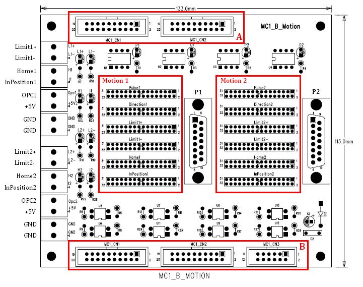
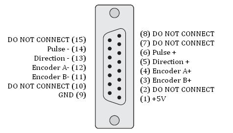
17 MC1_B_Motion Board LAYOUT P1&P Definition 16
18 JUMPER Through the software setting, users could choose pins on MC CN1 port for pulse and direction signal output, and another pins on MC CN port for +limit, -limit, home and in-position signal input. At the same time, the jumper on the MC1_B_MOTION also need to adjust to match the input-output setting. Each input and output has 16 jumpers for setting (refer to Layout Motion1 & Motion) Jumper Definition Jumper Definition 1 Close MC1 Input 1 or Output Close MC1 Input 9 or Output 9 Close MC1 Input or Output 19 0 Close MC1 Input 10 or Output Close MC1 Input or Output 1 Close MC1 Input 11 or Output Close MC1 Input or Output Close MC1 Input 1 or Output Close MC1 Input 5 or Output Close MC1 Input 1 or Output Close MC1 Input 6 or Output Close MC1 Input 1 or Output Close MC1 Input 7 or Output Close MC1 Input 15 or Output Close MC1 Input 8 or Output 8 1 Close MC1 Input 16 or Output 16 Default Setting P1:Pulse => MC1 Output 16 P1:Direction => MC1 Output 15 Limit1+ => MC1 Input 16 Limit1- => MC1 Input 15 Home1 => MC1 Input 1 InPosition1 => MC1 Input 1 P:Pulse => MC1 Output 1 P:Direction => MC1 Output 1 Limit+ => MC1 Input 1 Limit- => MC1 Input 11 Home => MC1 Input 10 InPosition => MC1 Input 9 INPUT Wiring Diagram Common cathode sensor wiring diagram (Home position for example). I. Mothod1: Power supply from MC1_B_Motion. MC1_B_Motion Limit+ Limit- R1 0 1 U8 Sensor Vin 1 Vin Output Home Inposition OPC +5V +5V R17 0 R0 0 R6 0 1 U9 1 U10 1 U1 17
19 Power VCC MC1_B_Motion Limit+ Limit- R1 0 1 U8 Sensor VCC 1 VCC Output Home Inposition OPC +5V +5V R17 0 R0 0 R6 0 1 U9 1 U10 1 U1 Power II. Method: Power supply from external device. If VCC is more than 10V, must connect a 1KΩ resistance as series connection. Or MC1_B_MOTION will be damaged permanently. VCC MC1_B_Motion Limit+ Limit- R1 0 1 U8 Sensor VCC 1 VCC Output R Home Inposition OPC +5V +5V R17 0 R0 0 R6 0 1 U9 1 U10 1 U1 18
20 Common anode sensor wiring diagram (Home position for example). Must connect a 1KΩ as series connection. Or MC1_B_MOTION will be damaged permanently. MC1_B_Motion Limit+ Limit- R1 0 1 U8 Sensor Vin 1 Vin Output R 1k Home Inposition OPC +5V +5V R17 0 R0 0 R6 0 1 U9 1 U10 1 U1 Power VCC MC1_B_Motion Limit+ Limit- R1 0 1 U8 Sensor Vin 1 VCC Output R 1k Home Inposition OPC +5V +5V R17 0 R0 0 R6 0 1 U9 1 U10 1 U1 19
21 Marking Mate Setting: If laser type is IPG Fiber, output is restricted to use pin 1~16, and input is restricted to use pin 1~11,15,16. If laser type is SPI Fiber, output is restricted to use pin 1~5, and input is restricted to use pin 1~11. Setting: After executing C:\Program Files\MarkingMate\Drivers\MCx\Config.exe, click on Axis Control 1. Refer to the following picture (Motion1 is X Axis Motion is Y Axis). Refer to the following picture (Motion1 is R Axis) A. Set In Position Port as unoccupied input pin to use. B. Uncheck Enable to disable + limit and limit detecting functions. 0


22 Others: MC1_B_MOTION is provided MC1_CN1 & MC1_CN extension port ( Marked as Layout Part A) for using unoccupied GPIO conveniently. 1. Must assure connected I/O from extension port is unoccupied, or the board might be damaged permanently.. Remove jumper from unused I/O in Motion 1 & Motion to increase usable I/O pin. In order to connect MC1_B_Motion with MC, just need to connect MC CN1&CN to Layout Part B by pin to pin cable. Refer to the following picture. 1


23 Using RS- What is RS- RS- is a kind of serial port. Common type of RS- connector is 9 pin D-Sub. Some kinds of laser types needed to control by RS- port for tuning laser parameter, such as power percentage, frequency etc. Setting to use RS-to control laser Take GSI YAG laser controlled by RS- as example. After user has executed \MarkingMate\DM.exe, chosen MCx at Driver Name column, and picked GSI_YAG.cfg at Mode column, to apply the setting by clicking OK. The location of cfg file is \MarkingMate\Drivers\MCx\cfg\. Refer to the following picture: Open the given file by favorite text editor. There should be two instructions under [ENV] sector, such as RS=1 and COMPORT=XXX. RS=1 means control laser by RS-. XXX within COMPORT=XXX means the using Com Port number. Default value is 1 which means using COM port 1 to control laser. Manually change this value to assign other port if necessary.
24 Cable Wirings Proprietary Mode---Internal Power In this mode, D/A receiver consumes powers from Marking Controller. No external power is required. A 1-to-1 wiring is in this case. Controller Side P1 Description DA Side P5 Pin Signal Name Signal Name Pin 1 +1V +1V power to D/A +1V 1 DSTATUS+ Status input from D/A DSTATUS+ DATA+ Channel data stream to D/A DATA+ DSYNC+ Synchronization signal to D/A DSYNC+ 5 DCLK+ Clock signal to D/A DCLK V -1V power to D/A -1V 6 7 DSTATUS- Status input from D/A DSTATUS- 7 8 DATA- Channel data stream to D/A DATA- 8 9 DSYNC- Synchronization signal to D/A DSYNC DCLK- Clock signal to D/A DCLK Ground 11 1 Ground 1 1 5V +5V power to D/A 5V 1 1 Ground 1 15 Ground 15 Proprietary Mode---External Power In this mode, D/A receiver consumes powers from external power supplies. No common ground is needed. CN7 is used to supply powers. Controller Side P1 Description DA Side P5 Pin Signal Name Signal Name Pin 1 +1V Not Connected DSTATUS+ Status input from D/A DSTATUS+ DATA+ Channel data stream to D/A DATA+ DSYNC+ Synchronization signal to D/A DSYNC+ 5 DCLK+ Clock signal to D/A DCLK V Not Connected 7 DSTATUS- Status input from D/A DSTATUS- 7 8 DATA- Channel data stream to D/A DATA- 8 9 DSYNC- Synchronization signal to D/A DSYNC DCLK- Clock signal to D/A DCLK Ground 11 1 Ground 1 1 5V Not Connected 1 Not Connected 15 Not Connected XY-100 Mode --- MC controller side In this mode, MC is configured to driver a XY-100 compliant D/A board, which can be a foreign D/A board or a D/A receiver board in XY-100 Mode with proper DB5 converter.
25 15 pin DB15 to 5 pin DB5 (XY-100 TYPE) MC P1 ( DB15) Description XY-100 D/A (DB5) Pin Signal Signal Pin 1 +1V Not Connected DSTATUS+ Status input from D/A DSTATUS+ 19 DATA_X+ Channel 1 data stream CHANNEL1+ 16 DSYNC+ Synchronization signal to D/A DSYNC DCLK+ Clock signal to D/A DCLK V Not Connected 7 DSTATUS- Status input from D/A DSTATUS- 6 8 DATA_X- Channel 1 data stream CHANNEL1 9 DSYNC- Synchronization signal to D/A DSYNC 10 DCLK- Clock signal to D/A DCLK 1 11 Ground *** 1 Ground *** 1 5V Not Connected 1 DATA_Y+ Channel data stream CHANNEL DATA_Y- Channel data stream CHANNEL D/A receiver jumper settings III. Select output range Output JP18 JP1 JP JP JP8 JP9 JP0 JP JP5 JP6 JP7 ranges ±V ±5V ±10V : Close
26 CFG Descriptions [ENV] LaserMode=1 // 1:CO, :YAG1,:YAG,:YAG, PWM Delay=0 // Unit :us, YAG Mode MaxPower=100 // range: 0 ~ 100, default: 100% // Percentage of the power output, default: 100% MinFrequency=0.1 // range: >= 0, default: 0.1 // Minimum frequency set by UI MaxFrequency=60 // range: > 0, default: 60 // Maximum frequency set by UI MarkEnd_Out=0 // range: 0 ~ 17, default: 0 // Port no. of MarkEnd signal, // 0: no output signal // 1 ~ 16: port no. of CN1 (OUT1 ~ OUT16) // 17: means equal to the RGM_RDY port EndDelay=0 // range: >= 0, default: 0 // Lasting time of the MarkEnd signal // Unit: ms Shutter_Out=0 // range: 0 ~ 16, default: 0 // Port no. of Shutter ON/OFF signal // 0: Disable Shutter Out // 1 ~ 16: port no. of CN1 (OUT1 ~ OUT16) Lamp_Out=0 // range: 0 ~ 16, default: 0 // Port no. of Lamp ON/OFF signal // 0: Disable Lamp Out // 1 ~ 16: port no. of CN1 (OUT1 ~ OUT16) Align_Out=0 // range: 0 ~ 16, default: 0 // Port no. of Align light (pilot light) ON/OFF signal // 0: Disable Align light Out // 1 ~ 16: CN1 (OUT1 ~ OUT16) port Variable Polygon=1 // range: 0 / 1, default: 1 // Enable polygon delay depending on included // angle // 0: disable, 1: enable Get Object Info=0 // range: 0 / 1, default: 0 // Support (Get Object Information) mechanism // the mechanism is now controlled by AP, ignore it 5
27 Enable SoftStart=0 // range: 0 / 1, default: 0 // Enable SoftStart for CO mode // 0: disable, 1: enable Lock Start Signal=0 // range: 0 / 1, default: 0 // (get_start_signal) command can Query the Start // Signal after MarkEnd and lock the signal // only special-made AP support it // Disabled when Mark On Fly=1 FPS=10 // FPS signal value for YAG Laser // Unit: 1 us Mark On Fly=0 // range: 0 / 1, default: 0 // Enable off-line marking // 0: disable, 1: enable // When enabled, the Lock Start Signal will be // ignored HT I/O Config=0 // range: 0 / 1, default: 0 // Planning as PGM RDY or Rdy for Start Signal // 0: planning as PGM RDY signal // 1: planning as Rdy for Start signal PGM RDY Signal Reverse=0 // range: 0 / 1, default: 0 // Enable PGM RDY signal reverse // 0: PGM RDY signal is active high // 1: PGM RDY signal is active low [STAND-BY] Period Time=000 // range : 0 ~ 6555,default : 000 // Period time of CO Laser s PWM signal on // Stand-by // Unit: 0.1 us Pulse Width=10 // range : 0 ~ 6555,default : 10 // Pulse width of CO Laser s PWM signal on // Stand-by // Unit: 0.1 us [SOFTSTART] Level-1=0 // range : 0% ~ 100%,percentage value of the 16 Level-=0 // points before Laser ON. Level-=0 Level-=0 Level-5=0 Level-6=0 Level-7=0 Level-8=0 Level-9=0 6
28 Level-10=0 Level-11=0 Level-1=0 Level-1=0 Level-1=0 Level-15=0 Level-16=0 [IPG] MO Job Start=0 // range: 0 / 1, default: 0 // Enable the MO signal of IPG Laser before // marking // 0: disable, 1: enable [IFL] // IPG Laser pin no. description Bit0=1 // range: 1 ~ 16 Bit1= // IPG Power Setting (0 ~ FFH), DO (LSB) ~ D7 // signal Bit= // port Bit= Bit=5 Bit5=6 Bit6=7 Bit7=8 Latch=9 // range: 1 ~ 16 // power data latch signal port Laser Status=10 // Master Oscillator signal port Aim Laser=11 // Align light (pilot light) signal port Duty Cycle=5 // 0.5 us, IPG duty cycle (0.1 us ~ 0.9 us) 7

29 Config.exe Descriptions Config.exe is a driver program installed in the directory of C:\Program Files\MarkingMate\Drivers\MC1. This program is used to do more settings of MC-1 controller. Please see the descriptions below to learn how to do the settings. System Settings Double click the Config.exe program will see the dialogue box as below: Laser Mode: Select CO, Yag1, Yag, or Yag from the pull down menu Enable Off-line Mark: Enable the off-line mark function Enable Variable Polyline Delay: Enable polyline delay function Enable Mark On Fly: Enable mark on fly function PGM_RDY Signal Reverse: Reverse the Program Ready signal 8
30 Softstart Setting Enable Softstart: Enable software control function Level: Adjust the power level (from 0% to 100%) from pulse-1 to pulse-16 separately. Auto-Recycle Enable: Enable auto-recycle function Delay: The delay time between each cycle [sec] First Pulse Suppress: The suppress time of the first pulse [us] (CO) stand-by signal Frequency: The frequency of CO laser [KHz] Pulse Width: The pulse width of CO laser [0.1us] Mark End Signal Enable: Enable Mark End signal Use PGM_RDY Signal: Use the Program Ready signal OUT Port: The port number of the signal Period Time: The remain time of the signal [ms] External Start Signal: Enable external start signal Software Lock Start Signal: Enable software lock start signal Enable Get Object Information: Enable get object information 9
: Port number of Direction signal In Position port (IN): Port number of In Position signal In Home port (IN): Port number of In Home")
31 Axis Control Settings Click the label of Axis Control will see the dialogue box as below: Rotary Axis Definition Enable: Enable Rotary Axis settings Pulse port (OUT): Port number of Pulse signal Direction port (OUT): Port number of Direction signal In Position port (IN): Port number of In Position signal In Home port (IN): Port number of In Home signal 0
32 X Axis Definition Enable: Enable X Axis settings Pulse port (OUT): Port number of Pulse signal Direction port (OUT): Port number of Direction signal In Position port (IN): Port number of In Position signal In Home port (IN): Port number of In Home signal Enable Limit Switches: Enable Limit Switches Active High: Set active high Limit (-) port (IN): Port number of Limit (-) signal Limit (+) port (IN): Port number of Limit (+) signal Enable Software Limit: Enable software control limit switch Limit (-) Pulse Count: Count number of Limit (-) signal Limit (+) Pulse Count: Count number of Limit (+) signal Y Axis Definition Enable: Enable Y Axis settings Pulse port (OUT): Port number of Pulse signal Direction port (OUT): Port number of Direction signal In Position port (IN): Port number of In Position signal In Home port (IN): Port number of In Home signal Enable Limit Switches: Enable Limit Switches Active High: Set active high Limit (-) port (IN): Port number of Limit (-) signal Limit (+) port (IN): Port number of Limit (+) signal Enable Software Limit: Enable software control limit switch Limit (-) Pulse Count: Count number of Limit (-) signal Limit (+) Pulse Count: Count number of Limit (+) signal 1
![Power Settings Click the label of Power Setting will see the dialogue box as below: Enable Power Control: Enable power control settings Step Power: Step power change ratio [%] Warm up power: Warm up](/docs-images/72/67390986/images/33-0.jpg "power [%] Warm up delay: Warm up delay time [sec] Warm up keep time: Warm up keep time [sec] Standby power: Standby power [%] Standby power delay: Standby power delay time [sec] Work power: Work")
33 Power Settings Click the label of Power Setting will see the dialogue box as below: Enable Power Control: Enable power control settings Step Power: Step power change ratio [%] Warm up power: Warm up power [%] Warm up delay: Warm up delay time [sec] Warm up keep time: Warm up keep time [sec] Standby power: Standby power [%] Standby power delay: Standby power delay time [sec] Work power: Work power initial value [%] Work power delay: Work power initial value delay time [sec] Power on delay: Power on delay time [sec]
34 Power on waiting: Time period from power on to stable [sec] Mark End Power: Mark end power [%] Mark End Delay: Mark end power delay time [sec]
Embedded Flying Marking Control System Hardware User Manual
 Embedded Flying Marking Control System Hardware User Manual Shenzhen RuiDa Technology CO., LTD Tel: 86-0755-26066687 Fax: 86-0755-26982287 Web: www.rd-acs.com E-Mail: support@rd-acs.com Add: 1B-1, Building
USBLMC_CUH_ IPG_V1(4) IPG Board
 IPG Board") USBLMC_CUH_ IPG_V1(4) USBLMC Client Use Handbook IPG Board Version Date Author Comment V1.2 2008-5-29 V1.3 2009-8-1 V1.4 2010-3-23 BJJCZ II All rights reserved Catalog Safety During Installation And Operation...1
USBLMC_CUH_ IPG_V1(4) USBLMC Client Use Handbook IPG Board Version Date Author Comment V1.2 2008-5-29 V1.3 2009-8-1 V1.4 2010-3-23 BJJCZ II All rights reserved Catalog Safety During Installation And Operation...1
Laser Marking Cards and Laser Marking Software
 1. LMX Series Marking Cards and Software Laser Marking Cards and Laser Marking Software LMX Marking Control Card is especially developed for scan head and laser control in real time with a PCI bus interface.
Hardware Guide. Control Made Simple. Model 401A Signal Generator
 Control Made Simple Model 401A Signal Generator Hardware Guide ON OFF LIMIT 1 2 3 4 RXD TXD POWER West Coast Office 1263 El Camino Real Menlo Park, CA 94025 Phone (650) 853-1444 Fax (650) 853-1405 www.flashcutcnc.com
EVDP610 IXDP610 Digital PWM Controller IC Evaluation Board
 IXDP610 Digital PWM Controller IC Evaluation Board General Description The IXDP610 Digital Pulse Width Modulator (DPWM) is a programmable CMOS LSI device, which accepts digital pulse width data from a
USB Multifunction Arbitrary Waveform Generator AWG2300. User Guide
 USB Multifunction Arbitrary Waveform Generator AWG2300 User Guide Contents Safety information... 3 About this guide... 4 AWG2300 specifications... 5 Chapter 1. Product introduction 1 1. Package contents......
MSCF-16-LN (Data sheet V5.0_01)
") (Data sheet V5.0_01) 16 fold Spectroscopy Amplifier with active BLR, CFDs, and Multiplicity Trigger mesytec MSCF-16-LN is an ultra low noise spectroscopy amplifier with active baseline restorer. It provides
(Data sheet V5.0_01) 16 fold Spectroscopy Amplifier with active BLR, CFDs, and Multiplicity Trigger mesytec MSCF-16-LN is an ultra low noise spectroscopy amplifier with active baseline restorer. It provides
AVL-10000T AUDIO VIDEO LINK TRANSMITTER TECHNICAL MANUAL
 AVL-10000T AUDIO VIDEO LINK TRANSMITTER TECHNICAL MANUAL Document : AVL-10000T Version: 1.00 Author: Henry S Date: 25 July 2008 This module contains protection circuitry to guard against damage due to
MSCF-16- PMT V
 MSCF-16- PMT V4.0-1.0 16 fold Spectroscopy Amplifier with CFDs and Multiplicity Trigger mesytec MSCF-16-PMT is an integrating shaping / timing filter amplifier with constant fraction discriminator and
MSCF-16 F (Data sheet V51_02)
") (Data sheet V51_02) 16 fold Spectroscopy Amplifier with CFDs and Multiplicity Trigger mesytec is a shaping / timing filter amplifier with constant fraction discriminator and multiplicity trigger and provides
(Data sheet V51_02) 16 fold Spectroscopy Amplifier with CFDs and Multiplicity Trigger mesytec is a shaping / timing filter amplifier with constant fraction discriminator and multiplicity trigger and provides
USB4. Encoder Data Acquisition USB Device Page 1 of 8. Description. Features
 USB4 Page 1 of 8 The USB4 is a data acquisition device designed to record data from 4 incremental encoders, 8 digital inputs and 4 analog input channels. In addition, the USB4 provides 8 digital outputs
Introduction. IO Ports. Description of signals. Scanhead Control Signals
 LMC-1 User's Manual Table of Contents Introduction... 3 IO Ports... 3 Description of signals... 3 Scanhead Control Signals... 3 LASER... 4 PWM, ANAPORT1, ANAPORT2... 4 FPK [ first pulse killer ]... 4 Extended
GPS Time and Frequency Reference Receiver
 $ GPS Time and Frequency Reference Receiver Symmetricom s 58540A GPS time and frequency reference receiver features: Eight-channel, parallel tracking GPS engine C/A Code, L1 Carrier GPS T-RAIM satellite
Logosol AC/DC Intelligent Servo Drive for Coordinated Control LS-174WP
 Features Motors supported: - Panasonic A and S series - Brushless 60/120 commutated - Brush-commutated (DC) motors Up to 20A peak, 12A continuous output current 12 to 90VDC power supply Separate motor
MTY (81)
") This manual describes the option "d" of the SMT-BD1 amplifier: Master/slave electronic gearing. The general information about the digital amplifier commissioning are described in the standard SMT-BD1 manual.
This manual describes the option "d" of the SMT-BD1 amplifier: Master/slave electronic gearing. The general information about the digital amplifier commissioning are described in the standard SMT-BD1 manual.
Absolute encoder GEL 15X F. Serial (SSI) or parallel interface, PC-programmable. Technical information version 01.06
 or parallel interface, PC-programmable. Technical information version 01.06") Absolute encoder 5xF Serial (SSI) or parallel interface, PC-programmable Technical information version 0.06 converter module KM 50.0 - + 24 V DC + 0% 5X F connecting cable VK 50.2 (SSI) VK 50.3 (parallel)
Absolute encoder 5xF Serial (SSI) or parallel interface, PC-programmable Technical information version 0.06 converter module KM 50.0 - + 24 V DC + 0% 5X F connecting cable VK 50.2 (SSI) VK 50.3 (parallel)
Jaguar Motor Controller (Stellaris Brushed DC Motor Control Module with CAN)
") Jaguar Motor Controller (Stellaris Brushed DC Motor Control Module with CAN) 217-3367 Ordering Information Product Number Description 217-3367 Stellaris Brushed DC Motor Control Module with CAN (217-3367)
Jaguar Motor Controller (Stellaris Brushed DC Motor Control Module with CAN) 217-3367 Ordering Information Product Number Description 217-3367 Stellaris Brushed DC Motor Control Module with CAN (217-3367)
DPFHP451 HIGH PERFORMANCE BILEVEL STEP MOTOR / MANUAL PRESET INDEXER DRIVER PACK
 DPFHP451 HIGH PERFORMANCE BILEVEL STEP MOTOR / MANUAL PRESET INDEXER DRIVER PACK Internal Index Count switches Pulse Rates up to 14,792 pulses per second CW & CCW Home, Hard, & Soft Limit Inputs Adjustable
Tarocco Closed Loop Motor Controller
 Contents Safety Information... 3 Overview... 4 Features... 4 SoC for Closed Loop Control... 4 Gate Driver... 5 MOSFETs in H Bridge Configuration... 5 Device Characteristics... 6 Installation... 7 Motor
Logosol Intelligent Hall-Servo Drive LS-173U Doc # / Rev. C, 02/12/2008
 Features Specially designed for control of brushless motors without encoder Hall-Servo and Encoder-Servo control modes Motors supported: - Brushless 60/120 commutated (AC) - Brush-commutated (DC) Up to
Model LIA100. Lock-in Amplifier
 Model LIA100 Lock-in Amplifier Operations Manual Thorlabs, Inc 435 Route 206 Newton, NJ 07860 P-(973) 579-7227 F-(973) 300-3600 www.thorlabs.com Doc. Page 1 of 10 Table of Contents Chapter Description
Application Note #1216
 Application Note #1216 ICM-1460 Interconnect Module The ICM-1460 (Rev G) Interconnect Module provides easy connections between the Econo series (DMC-1410, 1411, 1412, 1415, 1416, 1417, 1425) or E series
ADS9850 Signal Generator Module
 1. Introduction ADS9850 Signal Generator Module This module described here is based on ADS9850, a CMOS, 125MHz, and Complete DDS Synthesizer. The AD9850 is a highly integrated device that uses advanced
maxon document number:
 maxon document number: 791272-04 1 Table of contents... 2 2 Table of figures... 3 3 Introduction... 4 4 How to use this guide... 4 5 Safety Instructions... 5 6 Performance Data... 6 6.1 Motor data... 6
ArduCAM USB Camera Shield
 ArduCAM USB Camera Shield Application Note for MT9V034 Rev 1.0, June 2017 Table of Contents 1 Introduction... 2 2 Hardware Installation... 2 3 Run the Demo... 3 4 Tune the Sensor Registers... 4 4.1 Identify
USBLMC_CUH_DIGIT_V1(2)_EN. Digital Board
_EN. Digital Board") USBLMC_CUH_DIGIT_V1(2)_EN USBLMC Client Use Handbook Digital Board Version Date Author Comment V1.2 2008-5-29 BJJCZ II All rights reserved Catalog Safety During Installation And Operation...1 I. Common
USBLMC_CUH_DIGIT_V1(2)_EN USBLMC Client Use Handbook Digital Board Version Date Author Comment V1.2 2008-5-29 BJJCZ II All rights reserved Catalog Safety During Installation And Operation...1 I. Common
3.3V regulator. JA H-bridge. Doc: page 1 of 7
 Cerebot Reference Manual Revision: February 9, 2009 Note: This document applies to REV B-E of the board. www.digilentinc.com 215 E Main Suite D Pullman, WA 99163 (509) 334 6306 Voice and Fax Overview The
Brushless Servo Motor Drives xdrive Series
 Brushless Servo Motor Drives xdrive Series All-Digital, AC-Input, Velocity or Torque Control Allied Motion s xdrive servo drives are precision, all-digital DSP-based servo drive amplifiers capable of supplying
OVEN INDUSTRIES, INC. Model 5C7-362
 OVEN INDUSTRIES, INC. OPERATING MANUAL Model 5C7-362 THERMOELECTRIC MODULE TEMPERATURE CONTROLLER TABLE OF CONTENTS Features... 1 Description... 2 Block Diagram... 3 RS232 Communications Connections...
LC-10 Chipless TagReader v 2.0 August 2006
 LC-10 Chipless TagReader v 2.0 August 2006 The LC-10 is a portable instrument that connects to the USB port of any computer. The LC-10 operates in the frequency range of 1-50 MHz, and is designed to detect
Manual IF2008A IF2008E
 Manual IF2008A IF2008E PCI Basis Board Expansion Board Table of Content 1 Technical Data... 4 1.1 IF2008A Basic Printed Circuit Board... 4 1.2 IF2008E Expansion Board... 5 2 Hardware... 6 2.1 View IF2008A...
TLE9879 EvalKit V1.2 Users Manual
 TLE9879 EvalKit V1.2 Users Manual Contents Abbreviations... 3 1 Concept... 4 2 Interconnects... 5 3 Test Points... 6 4 Jumper Settings... 7 5 Communication Interfaces... 8 5.1 LIN (via Banana jack and
An RS485 bus is used for command, monitoring and diagnostic information that can be supplied to a system controller.
 The TCP3500 series is an AC-DC converter with adjustable DC output and universal 3-phase AC input. Conduction cooling (No Fans) makes this power supply series suitable for a wide variety of Industrial
Ocean Controls KT-5221 Modbus IO Module
 Ocean Controls Modbus IO Module 8 Relay Outputs 4 Opto-Isolated Inputs 2 Analog Inputs (10 bit) 1 PWM Output (10 bit) 4 Input Counters Connections via Pluggable Screw Terminals 0-5V or 0-20mA Analog Inputs,
G3P-R232. User Manual. Release. 2.06
 G3P-R232 User Manual Release. 2.06 1 INDEX 1. RELEASE HISTORY... 3 1.1. Release 1.01... 3 1.2. Release 2.01... 3 1.3. Release 2.02... 3 1.4. Release 2.03... 3 1.5. Release 2.04... 3 1.6. Release 2.05...
LCC-10 Product manual
 LCC-10 Product manual Rev 1.0 Jan 2011 LCC-10 Product manual Copyright and trademarks Copyright 2010 INGENIA-CAT, S.L. / SMAC Corporation Scope This document applies to i116 motion controller in its hardware
Brushed DC Motor Control. Module with CAN (MDL-BDC24)
") Stellaris Brushed DC Motor Control Module with CAN (MDL-BDC24) Ordering Information Product No. MDL-BDC24 RDK-BDC24 Description Stellaris Brushed DC Motor Control Module with CAN (MDL-BDC24) for Single-Unit
Stellaris Brushed DC Motor Control Module with CAN (MDL-BDC24) Ordering Information Product No. MDL-BDC24 RDK-BDC24 Description Stellaris Brushed DC Motor Control Module with CAN (MDL-BDC24) for Single-Unit
isys-4004 GUI interface - V2.1 Power up Initialize Peripheral Start Measurement YES LED flashes red Object available LED blinking
 isys-4004 GUI interface - V2.1 Power up Initialize Peripheral Start Measurement Mode Object available YES LED flashes red NO LED blinking isys-4004 distance sensor GUI description content 1. connecting
FEATURES DESCRIPTION THE OEM ADVANTAGE
 FEATURES PMAC2 controller from Delta-Tau controls amp bridge directly MODEL POWER I-CONT (A) I-PEAK (A) 7229AC 32~132VAC 10 20 7429AC 32~264VAC 10 20 Serial digital current feedback from U & V phases Mini
PM50. Technical Data TECHNOSOFT. DSP Motion Solutions. Power Module for DC, Brushless DC and AC Motors. Version 3.0. PM50 v3.0.
 Version 3.0 PM50 TECHNOSOFT DSP Motion Solutions Power Module for DC, Brushless DC and AC Motors Technical Data Technosoft 2001 Technosoft 2001 1-1 PM50 v3.0 Technical Data TECHNOSOFT DSP Motion Solutions
QUICK START GUIDE FOR DEMONSTRATION CIRCUIT BIT DIFFERENTIAL INPUT DELTA SIGMA ADC LTC DESCRIPTION
 LTC2433-1 DESCRIPTION Demonstration circuit 745 features the LTC2433-1, a 16-bit high performance Σ analog-to-digital converter (ADC). The LTC2433-1 features 0.12 LSB linearity, 0.16 LSB full-scale accuracy,
Ezi-STEP MINI Characteristics
 Ezi-STEP MINI Characteristics Ezi-STEP MINI is a micro stepping system that incorporates a motor and DSP (Digital Signal Processor) equipped drive that is integrated seamlessly together as a system. This
USBLMC_CUH_DIGIT_V2(1) Digital Board
 Digital Board") USBLMC_CUH_DIGIT_V2(1) USBLMC Client Use Handbook Digital Board Version recorder version Date Comment V1.0 2007-1 V1.1 2007-6 V1.2 2008-5-21 Assort all the material and make it a document. V1.3 2010.7
USBLMC_CUH_DIGIT_V2(1) USBLMC Client Use Handbook Digital Board Version recorder version Date Comment V1.0 2007-1 V1.1 2007-6 V1.2 2008-5-21 Assort all the material and make it a document. V1.3 2010.7
Datasheet. Octadrive DSP-CN * Applies to Part Number: *This unit has a CobraNet interface installed
 OCTADRIVE DSP-CN Datasheet Applies to Part Number: 391030 Octadrive DSP-CN * *This unit has a CobraNet interface installed User Notice: No part of this document including the software described in it may
STEPPING MOTOR EMULATION
 OPERATING MANUAL SERIES SMTBD1 OPTIONAL FUNCTIONS (Version 2.0) European version 2.0 STEPPING MOTOR EMULATION OPTION C This manual describes the option "C" of the SMT-BD1 amplifier: Stepping motor emulation.
Application Note #1245
 Application Note #1245 ICM-1460-20W Interconnect Module with 20W Servo Drive The ICM-1460-20W (Rev D) Interconnect Module provides an on board 20W linear servo drive for the X-axis suitable for driving
Peak Current. Continuous Current. See Part Numbering Information on last page of datasheet for additional ordering options.
 Description Power Range The PWM servo drive is designed to drive brushless DC motors at a high switching frequency. A single red/green LED indicates operating status. The drive is fully protected against
X3M. Multi-Axis Absolute MEMS Inclinometer Page 1 of 13. Description. Software. Mechanical Drawing. Features
 Page 1 of 13 Description The X3M is no longer available for purchase. The X3M is an absolute inclinometer utilizing MEMS (micro electro-mechanical systems) technology to sense tilt angles over a full 360
Fiber Laser Terminal Operating Manual
 Fiber Laser Terminal Operating Manual Model:RDAcc_Fiber V1.2 Shenzhen RuiDa Technology CO., LTD Tel: 86-0755-26066687 Fax: 86-0755-26982287 Web: www.rd-acs.com E-Mail: support@rd-acs.com Add: 1B-1, Building
DC Brushed Motor Controller Module EDP-AM-MC1
 Embedded Development Platform DC Brushed Motor Controller Module EDP-AM-MC1 Electrocomponents plc Vsn 1.1 Page 1 DC Brushed Motor Controller Module EDP-AM-MC1 The motor controller module is designed to
PCE-M134-LD. PCE-M134-LD User Manual TPM. Version: V Jun01. To properly use the product, read this manual thoroughly is necessary.
 PCE-M4-LD Version: V.0 206Jun0 To properly use the product, read this manual thoroughly is necessary. Part No.: 8-02400-00 Revision History Date Revision Description 206/06/0.0 Document creation. 2 Copyright
Operation Manual Communication function
 HRX-OM-M091-G 1 st edition: Jul. 2009 7 th edition: Feb.2011 Operation Manual Communication function Thermo chiller Air-Cooled refrigerated type HRS012-A-10- HRS018-A-10- HRS012-A-20- HRS018-A-20- HRS024-A-20-
NI 6013/6014 Family Specifications
 NI 6013/6014 Family Specifications This document lists the I/O terminal summary and specifications for the NI 6013/6014 family of devices. This family includes the following devices: NI PCI-6013 NI PCI-6014
SilverMax Datasheet. QuickSilver Controls, Inc. NEMA 23 Servomotors.
 SilverMax Datasheet NEMA 23 Servomotors QuickSilver Controls, Inc. www.quicksilvercontrols.com SilverMax Datasheet - NEMA 23 Servomotors 23 Frame Sizes: 23-3, 23-5, 23H-1, 23H-3, 23H-5 / Series: E, E3,
AMP-19520/40. Multi-axis Brushless/Brush Servo Amplifier. By Galil Motion Control, Inc. Rev. 1.0d
 Multi-axis Brushless/Brush Servo Amplifier AMP-9520/40 Rev..0d By Galil Motion Control, Inc. Galil Motion Control, Inc. 270 Technology Way Rocklin, California 95765 Phone: (96) 626-00 Fax: (96) 626-002
Integrated Servo Motor UCS57
 Integrated Servo Motor Introduction is a new generation of high performance digital integrated servo drive motor, which is a series of low voltage AC servo products integrated with AC servo motor and drive
ArduCAM USB Camera Shield
 ArduCAM USB Camera Shield Application Note for MT9J001 Rev 1.0, Aug 2017 Table of Contents 1 Introduction... 2 2 Hardware Installation... 2 3 Run the Demo... 3 4 Tune the Sensor Registers... 4 4.1 Identify
AxCent Servo Drive A25A100
 Description Power Range The A25A100 PWM servo drive is designed to drive brush type DC motors at a high switching frequency. A single red/green LED indicates operating status. The drive is fully protected
USB-PWM10. User s Manual
 USB-PWM10 User s Manual Windows, Windows2000, Windows NT and Windows XP are trademarks of Microsoft. We acknowledge that the trademarks or service names of all other organizations mentioned in this document
PCL-836 Multifunction countertimer and digital I/O add-on card for PC/XT/ AT and compatibles
 PCL-836 Multifunction countertimer and digital I/O add-on card for PC/XT/ AT and compatibles Copyright This documentation is copyrighted 1997 by Advantech Co., Ltd. All rights are reserved. Advantech Co.,
EVAcharge SE Datasheet
 EVAcharge SE Datasheet I2SE GmbH December 6, 2016 1/36 Revisions Revision Release Date Changes 7 December 06, 2016 Fixed LGE field in USS request control PWM, add note that USS service 0x11 requires an
7I33/7I33T MANUAL Quad analog servo amp interface
 7I33/7I33T MANUAL Quad analog servo amp interface V1.4 This page intentionally almost blank Table of Contents GENERAL.......................................................... 1 DESCRIPTION.................................................
Series 48 Water Cooled Laser & UC-2000 Quick Start Guide
 Important Read all Danger, Warning, Caution terms, symbols, and instructions located in the (Laser Safety Hazard information) sections in the Series 48 Laser Operation Manuals. http://www.synrad.com/synrad/docroot/resources/libraries/manuals
No Gain Tuning. Hunting. Closed Loop System
 2 No Gain Tuning Conventional servo systems, to ensure machine performance, smoothness, positional error and low servo noise, require the adjustment of its servo s gains as an initial crucial step. Even
Continental Hydraulics Installation Manual CEM-RA-A
 CEM-RA-A Description: This ramp amplifier drives either single or dual solenoid proportional valve coils up to 2.6A. It is suitable to control current to either proportional directional, flow, or pressure
ECE 511: FINAL PROJECT REPORT GROUP 7 MSP430 TANK
 ECE 511: FINAL PROJECT REPORT GROUP 7 MSP430 TANK Team Members: Andrew Blanford Matthew Drummond Krishnaveni Das Dheeraj Reddy 1 Abstract: The goal of the project was to build an interactive and mobile
Testra Corporation ss483 Series Microstepping Motor Driver. Specifications Sep SoftStep FIRMWARE FEATURES
 SoftStep The New Art of Stepper Motor Control With SoftStep you get the benefits of ultra smooth microstepping regardless of your selected step size. The intelligent on board processor treats the input
B Robo Claw 2 Channel 25A Motor Controller Data Sheet
 B0098 - Robo Claw 2 Channel 25A Motor Controller Feature Overview: 2 Channel at 25A, Peak 30A Hobby RC Radio Compatible Serial Mode TTL Input Analog Mode 2 Channel Quadrature Decoding Thermal Protection
Series 48 Air Cooled Laser & UC-2000 Quick Start Guide
 Important Read all Danger, Warning, Caution terms, symbols, and instructions located in the (Laser Safety Hazard information) sections in the Series 48 Laser Operation Manuals. http://www.synrad.com/synrad/docroot/resources/libraries/manuals.
USB-MC USB Motion Controller
 USB-MC USB Motion Controller Con2 I/O port, to I/O card Con4 Aux port, inputs and outputs Con3 parallel port, to I/O card Con1 USB port to PC Con5 external power supply 8 24 VDC Status LED - + Comm. LED
DEMO CIRCUIT 1004 ADC DRIVER AND 7X7MM HIGH-PERFORMANCE ADC QUICK START GUIDE ADC Driver and 7x7mm High-Performance ADC DESCRIPTION
 DEMO CIRCUIT 1004 QUICK START GUIDE ADC Driver and 7x7mm High-Performance ADC DESCRIPTION Demonstration circuit 1004 is a reference design featuring Linear Technology Corporation s Analog- Digital Converter
5008 Dual Synthesizer Configuration Manager User s Guide (admin Version) Version valontechnology.com
 Version valontechnology.com") 5008 Dual Synthesizer Configuration Manager User s Guide (admin Version) Version 1.6.1 valontechnology.com 5008 Dual Synthesizer Module Configuration Manager Program Version 1.6.1 Page 2 Table of Contents
5008 Dual Synthesizer Configuration Manager User s Guide (admin Version) Version 1.6.1 valontechnology.com 5008 Dual Synthesizer Module Configuration Manager Program Version 1.6.1 Page 2 Table of Contents
BusWorks 900EN Series Modbus TCP/IP 10/100M Industrial Ethernet I/O Modules
 BusWorks 900EN Series Modbus TCP/IP 10/100M Industrial Ethernet I/O Modules Six Differential Current Inputs Six Differential Voltage Inputs USER S MANUAL ACROMAG INCORPORATED Tel: (248) 295-0880 30765
LoadCell Board Application Note
 LoadCell Board Application Note 1. What is loadcell 1.1. Loadcell Loadcell is one kind of bridge sensor. Loadcell is a passtive resistant sensor. The resistance varies for the change of the force. The
4I36 QUADRATURE COUNTER MANUAL
 4I36 QUADRATURE COUNTER MANUAL 1.3 for Firmware Rev AA05,BB05 or > This page intentionally not blank - Table of Contents GENERAL.......................................................... 1 DESCRIPTION.................................................
Copyright 2014 YASKAWA ELECTRIC CORPORATION All rights reserved. No part of this publication may be reproduced, stored in a retrieval system, or
 Copyright 2014 YASKAWA ELECTRIC CORPORATION All rights reserved. No part of this publication may be reproduced, stored in a retrieval system, or transmitted, in any form, or by any means, mechanical, electronic,
Analog Servo Drive 30A8
 Description Power Range The 30A8 PWM servo drive is designed to drive brush type DC motors at a high switching frequency. A single red/green LED indicates operating status. The drive is fully protected
DNT2400. Low Cost 2.4 GHz FHSS Transceiver Module with I/O
 2.4 GHz Frequency Hopping Spread Spectrum Transceiver Point-to-point, Point-to-multipoint, Peer-to-peer and Tree-routing Networks Transmitter Power Configurable from 1 to 63 mw RF Data Rate Configurable
Brushed DC Motor Microcontroller PWM Speed Control with Optical Encoder and H-Bridge
 Brushed DC Motor Microcontroller PWM Speed Control with Optical Encoder and H-Bridge L298 Full H-Bridge HEF4071B OR Gate Brushed DC Motor with Optical Encoder & Load Inertia Flyback Diodes Arduino Microcontroller
Frequently Asked Questions DAT & ZX76 Series Digital Step Attenuators
 Frequently Asked Questions DAT & ZX76 Series Digital Step Attenuators 1. What is the definition of "Switching Control Frequency"? The switching control frequency is the frequency of the control signals.
PulsePuppy Installation and Operation Manual Oscillator Carrier Revised: 30 January TAPR
 PulsePuppy Installation and Operation Manual Oscillator Carrier Revised: 30 January 2018 2018 TAPR Introduction The PulsePuppy is a carrier board for small user-provided oven controlled ( OCXO ) and temperature
INSTALLATION & OPERATION MANUAL
 INSTALLATION & OPERATION MANUAL PREFACE This installation & operation manual is intended as an instruction manual for trained person who is in charge of installation, maintenance, repair, etc. Before installation
Analog Servo Drive 25A20DD
 Description Power Range NOTE: This product has been replaced by the AxCent family of servo drives. Please visit our website at www.a-m-c.com or contact us for replacement model information and retrofit
3DM phase Digital Stepper Drive
 3DM2283 3-phase Digital Stepper Drive 150-220VAC, 0.5-8.2A peak, Auto-configuration, Low Noise Anti-Resonance provides optimal torque and nulls mid-range instability Motor auto-identification and parameter
Revision 1. March 21, ADC Operation Manual N 11 th St San Jose CA
 Revision 1 March 21, 2017 ADC Operation Manual www.mountztorque.com - 1080 N 11 th St San Jose CA 95112 408.292.2214 1 Index 1. Installation 3 1.1 Required PC specification 3 1.2 Software 3 2. Operation
Table of Contents. HWIO-Gateway User Manual
 User Manual HWIO-Gateway INUX AB Katrinedalsg. 3, 504 51 Borås http://www.inux.se Copyright 2009 Uppdaterad 2010-01-12 Copyright 2009 INUX AB 1 Table of Contents 1. Product overview...3 2. License...3
User s Manual. ACPL-339J Isolated Gate Driver Evaluation Board. Quick-Start. Testing Either Arm of The Half Bridge Inverter Driver (without IGBT)
") ACPL-339J Isolated Gate Driver Evaluation Board User s Manual Quick-Start Visual inspection is needed to ensure that the evaluation board is received in good condition. The default connections of the evaluation
ACPL-339J Isolated Gate Driver Evaluation Board User s Manual Quick-Start Visual inspection is needed to ensure that the evaluation board is received in good condition. The default connections of the evaluation
Gentec-EO USA. T-RAD-USB Users Manual. T-Rad-USB Operating Instructions /15/2010 Page 1 of 24
 Gentec-EO USA T-RAD-USB Users Manual Gentec-EO USA 5825 Jean Road Center Lake Oswego, Oregon, 97035 503-697-1870 voice 503-697-0633 fax 121-201795 11/15/2010 Page 1 of 24 System Overview Welcome to the
Channels that are not occupied by temperature sensors, can take over alternative functions:
 Firmware /TEMP12 The /TEMP12 firmware allows you to connect up to twelve digital temperature sensors (type Dallas DS18B20). Data from twelve channels is transferred to your PC via USB. ONE temperature
AxCent Servo Drive A50A100
 Description Power Range The A50A100 PWM servo drive is designed to drive brushed type DC motors at a high switching frequency. A single red/green LED indicates operating status. The drive is fully protected
System Board 6219 MAXREFDES89#: MAX14871 Full-Bridge DC Motor Driver MBED Shield
 System Board 6219 MAXREFDES89#: MAX14871 Full-Bridge DC Motor Driver MBED Shield Introduction Brushed DC motors provide cost-effective, convenient motion in many applications ranging from electric toothbrushes
WiNRADiO WR-G35DDCi Multichannel Coherent Application Guide
 WiNRADiO WR-G35DDCi Multichannel Coherent Application Guide 1 Table of contents 1 Introduction... 3 2 Parts description of the coherent system... 4 2.1 WR-G35DDCi connectors... 4 2.2 The WiNRADiO Coherence
 Switch/ Jumper Table 1-1: Factory Settings Factory Settings (Jumpers Installed) Function Controlled Activates pull-up/ pull-down resistors on Port 0 digital P7 I/O lines Activates pull-up/ pull-down resistors
NJU6051. White LED Driver with Automatic Dimming Control PRELIMINARY ! PACKAGE OUTLINE
 White LED Driver with Automatic Dimming Control NJU6051 PRELIMINARY! GENERAL DESCRIPTION The NJU6051 is a white LED driver with an automatic dimming control. It contains an output driver, a PWM controller,
Understanding the Arduino to LabVIEW Interface
 E-122 Design II Understanding the Arduino to LabVIEW Interface Overview The Arduino microcontroller introduced in Design I will be used as a LabVIEW data acquisition (DAQ) device/controller for Experiments
IP 251 Universal Signal Converter SSI parallel RS232 parallel SSI RS232
 control motion interface ELEKTRO-TRADING sp. z o.o Tel. +48 (0-32) 734-55-72 Tel/Fax +48 (0-32) 734-55-70 E-Mail et@elektro-trading.com.pl http://www.elektro-trading.com.pl IP 251 Universal Signal Converter
DEMO CIRCUIT 1057 LT6411 AND LTC2249 ADC QUICK START GUIDE LT6411 High-Speed ADC Driver Combo Board DESCRIPTION QUICK START PROCEDURE
 DESCRIPTION Demonstration circuit 1057 is a reference design featuring Linear Technology Corporation s LT6411 High Speed Amplifier/ADC Driver with an on-board LTC2249 14-bit, 80MSPS ADC. DC1057 demonstrates
For more information on these functions and others please refer to the PRONET-E User s Manual.
 PRONET-E Quick Start Guide PRONET-E Quick Start Guide BASIC FUNCTIONS This guide will familiarize the user with the basic functions of the PRONET-E Servo Drive and assist with start up. The descriptions
RW1026 Dot Matrix 48x4 LCD Controller / Driver
 Features Operating voltage: 2.4V~5.5V Internal LCD Bias generation with voltage-follower buffer External resistor CR oscillator External 256k Hz frequency source input Selection of 1/2 or 1/3 bias, and
AxCent Servo Drive AZBE10A4IC
 Description Power Range The AZBE10A4C interface card and PWM servo drive assembly is designed to drive brushless and brushed DC motors at a high switching frequency. The interface card features quick-disconnect