TLE9879 EvalKit V1.2 Users Manual
|
|
|
- Phoebe Riley
- 6 years ago
- Views:
Transcription
... 8 5.2 UART (via USB)... 8 5.3 Debugging (via USB or SWD-Interface)... 9 6 Technical Data... 9 7 Optional Additional Placements... 10 8 Schematics and Layout.")
1 TLE9879 EvalKit V1.2 Users Manual Contents Abbreviations Concept Interconnects Test Points Jumper Settings Communication Interfaces LIN (via Banana jack and uio BSL) UART (via USB) Debugging (via USB or SWD-Interface) Technical Data Optional Additional Placements Schematics and Layout Schematic Layout Errata... 17
2 9.1 Short of internal layer 2 and Jumper (JP4) Related limitations: Workaround: Jumper (JP6) not connected to VDDP Related limitations: Workaround: Workaround Proposal
3 Abbreviations BLDC BSL Brushless Direct Current Bootstrap Loader GH1,2,3 Gate High side MOSFET for Phases 1, 2, 3 GL1,2,3 Gate Low side MOSFET for Phase 1, 2, 3 GPIO ISP LIN MON n.c. n/u OP1 OP2 RST SL SWD TMS UART VAREF VBAT VCOM VCP VDDC VDDEXT VDDP VDH VS General Port Input / Output In-system Programmer Local Interconnect Network Monitor not connected not used Negative operational Amplifier Input Positive operational Amplifier Input Reset Source Low side MOSFET ARM Serial Wire Debug Test Mode Select Universal Asynchronous Receiver Transmitter Reference Voltage Battery Voltage Supply Virtual COM-Port Voltage Charge Pump Core Supply External Voltage Supply Output I/O Port Supply Voltage Drain High side MOSFET Battery Supply Input VSD Table 1: Abbreviations Battery Supply Input for MOSFET Driver 3

4 1 Concept Figure 1: Board Concept This board is intended to provide a simple, easy-to-use tool for getting familiar with Infineon s embedded power IC TLE9879. It contains the TLE9879 and its typical application circuit including three MOSFET half bridges to instantly drive a BLDC motor. The board is ready to connect with car supply or similar and has an implemented Segger for debugging on board. All relevant chip pins are connected to pin headers at the edge of the board, where signals can be probed or applied directly (see Table 2, Table 3). By different jumper settings LEDs can be put in parallel to several ports and selected functions can be configured (see Table 6). Push button switches allow easy hardware reset and triggering of the MON input. There are intended test points for all six gate driver pins, for measurements at the shunt, VDDC and several ground points on the evaluation board (see Figure 3). For testing analog signals ADC inputs can be varied by the potentiometer on board. Three phases of motor current can be picked off at a terminal block to connect a DC brushless motor. The evaluation board can be operated by standard laboratory equipment as power supply and LIN communication are working via banana jacks. Debugging and UART are provided via an USB interface combined with onboard Segger J-Link (XMC4200). Bidirectional level shifters ensure that the respective XMC pins are in tristate as long as UART or debugging is not used. In case the user wants to use another ISP than the onboard Segger the SWD interface can be used. To program the TLE9879 via LIN there is an additional uio BSL interface (see Table 4). There is a battery LED that indicates that the board is connected to supply the right way. Otherwise reverse polarity protection secures the board from damage by cross connection. 4
 and LIN communication via banana jack: GND (black), VBAT (red), LIN (green) Pin Ports X4 and X5 (marked red) Soldering pin headers with 2,54mm pitch for X4 (1x10) and X5(1x16) yields test points")
5 2 Interconnects Figure 2: Interconnects Banana jacks (marked yellow) There are jacks in different colors for ground, supply (max.28v) and LIN communication via banana jack: GND (black), VBAT (red), LIN (green) Pin Ports X4 and X5 (marked red) Soldering pin headers with 2,54mm pitch for X4 (1x10) and X5(1x16) yields test points for the TLE9879 pins. Following signals are connected to the pins: X4: GND VCP VSD VS VDH LIN VDDEXT VDDP VAREF GND Table 2: Pin Configuration Top Line Pin Port (X4) X5: GND MON RST P0.0 P1.1 P0.1 P0.2 P0.3 P1.2 P1.0 P1.3 P1.4 P0.4 P2.3 P2.4 P2.5 Table 3: Pin Configuration Bottom Line Pin Port (X5) Terminal block for connecting the motor (marked blue) The three pins of the terminal block provide access to the three half bridges and are intended to connect a DC brushless motor. USB for UART and Debugging (marked green) With this Micro USB PC and evaluation board can get connected. 5
. n.c. 1 2 GND n.c. 3 4 n.c. LIN 5 6 VS RESET 7 8 n.c. Table 4: Pin Configuration uio BSL Pin Header for SWD (marked purple) There is a 10 pin header (2x5) with 1,27mm pitch on the evaluation board.")
6 uio BSL for LIN (marked orange) This uio bootstrap loader is an 8 pin header (2x4) with 2,54mm pitch. It is intended to connect additional hardware for bootstrap loading. For programming the TLE9879 via LIN this uio interface can be used (see n.c. 1 2 GND n.c. 3 4 n.c. LIN 5 6 VS RESET 7 8 n.c. Table 4: Pin Configuration uio BSL Pin Header for SWD (marked purple) There is a 10 pin header (2x5) with 1,27mm pitch on the evaluation board. For debugging with another ISP than the onboard Segger this interface can be used. DBPRE will be implicitly connected to GND by connecting the external ISP. This keeps the XMC in reset state to prevent interference of the SWD communication. 5V 1 2 SWDIO (TMS) GND 3 4 SWCLK (P0.0) GND 5 6 n.c. n.c. 7 8 n.c. DBPRE 9 10 RESET Table 5: Pin Configuration SWD Interface 3 Test Points Figure 3: Test Points 6
.")
7 The 3-phase power half-bridge is controlled by six gate driver pins, driving the gates of high side MOSFET and low side MOSFET for each phase. Each gate has an intended test point to measure the respective signals at high side gates and low side gates (GL1, GL2, GL3, GH1, GH2, GH3). Test points OP1 and OP2 are provided at both sides of the shunt, which is 5mR. Additionally there is an intended test point for VDDC and various ground points. All test points marked in the following figure are not populated. In order to use these pins they have to be soldered in the designated solder holes. 4 Jumper Settings The following table summarizes the jumpers options. More detailed information can be found in the text below. JP1 JP2 JP3 JP4 JP5 JP6 JP7 Table 6: Jumpers functionalities Enable or disable MON button Enable or disable RESET button Select TLE9879 as LIN Master or LIN Slave Connect or disconnect VAREF with VDDEXT Replace by an ampere meter to measure input current Enable or disable POTI Enable or disable LED for respective GPIO Figure 4: Jumpers JP1: Close this jumper to connect MON button to MON input. Open it to disconnect MON button from MON input. JP2: Close this jumper to connect RESET button to RESET input. Open it to disconnect RESET button from RESET input. 7
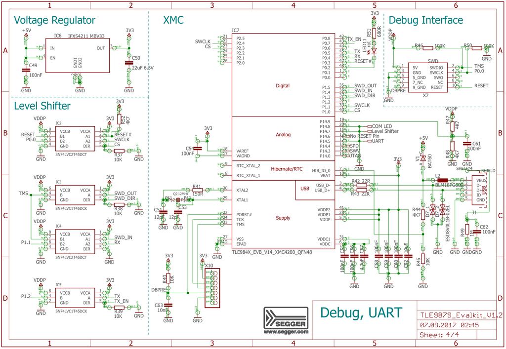
8 JP3: Close this jumper to connect an additional 1k pull-up resistor. This is intended for LIN master communication. Open the jumper to use the TLE9879 as slave in a LIN network. Software for LIN low level driver can be found at the homepage of IHR ( JP4: Close this jumper in order to supply VAREF by VDDEXT. In case VAREF is supplied externally the user has to take care by software that the internal VAREF is disabled. Open the jumper to use the internal VAREF which has to be enabled by software. JP5: This jumper is closed by default. If this jumper is left open the device is not supplied. It is intended to open the VS line in order to measure the current flowing into the TLE9879. JP6: Close this jumper to connect the potentiometer to P2.4. Open this jumper to disconnect the potentiometer. JP7: Jumper 7 provides one individual jumper per LED in order to connect or disconnect the respective LED to the pin port. P0.1 P0.2 P0.3 P1.2 P1.0 P1.3 P1.4 P0.4 LED1 LED2 LED3 LED4 LED5 LED6 LED7 LED8 Table 7: Combinations of GPIOs and LEDs 5 Communication Interfaces 5.1 LIN (via Banana jack and uio BSL) The device integrated LIN transceiver is connected to a banana jack and additionally to the uio BSL interface. To integrate the device in a LIN network it is sufficient to use the single wire banana interface. The BSL interface is intended to program the device via LIN. For further information about the uio interface see UART (via USB) A virtual COM port provided by Segger driver enables a PC board communication via UART. The UART2 module of TLE9879 uses the pins P1.1 (transmit) and P1.2 (receive). Those are connected to the XMC4200, which emulates Rx and Tx on PC side with Segger firmware. Though they cannot be disconnected physically, bidirectional level shifters ensure that the XMC pins are hi-z in case the virtual COM port is not used. By connecting the evaluation board to the PC a virtual COM port gets emulated by the Segger driver automatically. The port used will show up in the Microsoft Windows device manager. 8

9 Figure 5: UART and Debugging Note: Only one of the interfaces USB or SWD can be used at one time. While using the SWD interface the XMC is hold in reset. As long as a debugger is connected with the SWD interface it eliminates therefore debugging or UART via USB. 5.3 Debugging (via USB or SWD-Interface) For serial wire debug the TLE9879 uses the pins TMS (data) and P0.0 (clock). Level shifters between XMC4200 and TLE9879 allow using P0.0, while it is not used for debugging. The Segger J-Link module on board allows serial wire debugging via USB. Alternative debugging via SWD interface is possible to debug with another ISP than the onboard Segger e.g. U-Link2. Therefore the signals are routed through the 10 pin header SWD interface between the XMC4200 and the TLE9879. The pin configuration makes sure that the XMC is hold in reset while another debugger is physically connected as DBPRE will be implicitly connected to GND by connecting the external ISP (see Table 5). Information regarding the software installation for editor, compiler and debugger can be found in the documentation epower Tool Chain Setup SDK on the provided USB flash drive. 6 Technical Data Platine Size: (110x66) mm Voltage Supply: max. 28V Motor Current: max. 20A Pin Ports: 5V (GPIOs of TLE9879) 9

10 7 Optional Additional Placements Figure 6: Additional Placements positions Values for these optional additional placements have to be determined depending on application. Q1 External Oscillator C1 Oscillator Capacity 1 C2 Oscillator Capacity 2 R22 Resistance Snubber High side MOSFET Phase 1 C28 Capacity Snubber High side MOSFET Phase 1 C24 Gate Drain Capacity High side MOSFET Phase 1 R23 Resistance Snubber Low side MOSFET Phase 1 C29 Capacity Snubber Low side MOSFET Phase 1 C26 Gate Drain Capacity Low side MOSFET Phase 1 R28 Resistance Snubber High side MOSFET Phase 2 C36 Capacity Snubber High side MOSFET Phase 2 C32 Gate Drain Capacity High side MOSFET Phase 2 R29 Resistance Snubber Low side MOSFET Phase 2 C37 Capacity Snubber Low side MOSFET Phase 2 C34 Gate Drain Capacity Low side MOSFET Phase2 R35 Resistance Snubber High side MOSFET Phase 3 C45 Capacity Snubber High side MOSFET Phase 3 C41 Gate Drain Capacity High side MOSFET Phase 3 R36 Resistance Snubber Low side MOSFET Phase 3 C46 Capacity Snubber Low side MOSFET Phase 3 C43 Gate Drain Capacity Low side MOSFET Phase 3 Table 8: Additional Placements 10
11 8 Schematics and Layout 8.1 Schematic 11
12 12
13 13
14 14


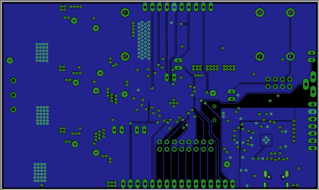
15 8.1 Layout Top Layer Layer 2 15

16 Layer 3 Bottom Layer 16
 Redesign activities caused a short between T2 supply line and VDDEXT Jumper.")
 not connected to VDDP. JP6 is not connected to VDDP voltage. PIN1 Related limitations: - Change of potentiometer position will not change analog value on port P2.")
17 9 Errata Note: TLE9879 Evalkit Rev 1.2 has some restrictions in functionality, which are described in this chapter. 9.1 Short of internal layer 2 and Jumper (JP4) Redesign activities caused a short between T2 supply line and VDDEXT Jumper. Related limitations: - VDDEXT cannot be used, when charge pump is enabled - Reverse polarity circuit not functional Workaround: - Remove Jumper (JP4) - Use VDDP instead of VDDEXT for evaluation. 9.2 Jumper (JP6) not connected to VDDP. JP6 is not connected to VDDP voltage. PIN1 Related limitations: - Change of potentiometer position will not change analog value on port P2.4 - Example Code, using the potentiometer is not functional without workaround Workaround: - Connect Pin 1 of JP6 with VDDP - Potentiometer can be used as expected 17

18 9.3 Workaround Proposal With this proposal, the VDDEXT PIN can be used again. Two vias has to be drilled with a 1.1mm drill bit. The vias are marked in red in the picture below. This workaround disconnect the reverse polarity MOSFET from the Charge-Pump voltage VCP. After the fix is applied, the VDDEXT can be used as specified. Note: The disconnected Transistor T1 can cause a voltage drop from VBAT connection to VDH voltage level. This voltage drop can be avoided by manually connecting the Gate Pin of T1 to the VCP voltage Pin (orange arrow). If the Evaluation Kit Sample Box is marked with Revision 1.2a, this fix is already applied. 18
Training Schedule. Robotic System Design using Arduino Platform
 Training Schedule Robotic System Design using Arduino Platform Session - 1 Embedded System Design Basics : Scope : To introduce Embedded Systems hardware design fundamentals to students. Processor Selection
Motor Control Development Kit
 User s Manual, V 1.0, June 2003 Motor Control Development Kit A reference design for low voltage 3-phase AC induction and brushless DC motor control. Microcontrollers Never stop thinking. Revision History:2003-06
3.3V regulator. JA H-bridge. Doc: page 1 of 7
 Cerebot Reference Manual Revision: February 9, 2009 Note: This document applies to REV B-E of the board. www.digilentinc.com 215 E Main Suite D Pullman, WA 99163 (509) 334 6306 Voice and Fax Overview The
TMC603EVAL MANUAL Evaluation board for the TMC603 three phase motor driver with BLDC back EMF commutation hallfx
 TMC603EVAL MANUAL Evaluation board for the TMC603 three phase motor driver with BLDC back EMF commutation hallfx TRINAMIC Motion Control GmbH & Co. KG Sternstraße 67 D 20357 Hamburg GERMANY www.trinamic.com
MLX83100 Automotive DC Pre-Driver EVB83100 for Brushed DC Applications with MLX83100
 EVB83100 for Brushed DC Applications with MLX83100 Stefan Poels JULY 17, 2017 VAT BE 0435.604.729 Transportstraat 1 3980 Tessenderlo Phone: +32 13 67 07 95 Mobile: +32 491 15 74 18 Fax: +32 13 67 07 70
System Board 6219 MAXREFDES89#: MAX14871 Full-Bridge DC Motor Driver MBED Shield
 System Board 6219 MAXREFDES89#: MAX14871 Full-Bridge DC Motor Driver MBED Shield Introduction Brushed DC motors provide cost-effective, convenient motion in many applications ranging from electric toothbrushes
JUMA-TRX2 DDS / Control Board description OH2NLT
 JUMA-TRX2 DDS / Control Board description OH2NLT 22.08.2007 General Key functions of the JUMA-TRX2 DDS / Control board are: - provide user interface functions with LCD display, buttons, potentiometers
EVDP610 IXDP610 Digital PWM Controller IC Evaluation Board
 IXDP610 Digital PWM Controller IC Evaluation Board General Description The IXDP610 Digital Pulse Width Modulator (DPWM) is a programmable CMOS LSI device, which accepts digital pulse width data from a
UM1994 User manual. Eval-L9907. Introduction
 User manual Eval-L9907 Introduction The EVAL-L9907 is an evaluation board designed to provide the user a platform for the L9907, a FET driver for 3 phase BLDC motor. The board offers all the main input/output
V 1.1 TABLE OF CONTENTS LIST OF FIGURES... 2 LIST OF TABLES... 2 HISTORY... 2
 HF-Z100 ZigBee Module Datasheet V 1.1 TABLE OF CONTENTS LIST OF FIGURES... 2 LIST OF TABLES... 2 HISTORY... 2 1. PRODUCT OVERVIEW... 3 1.1. General Description... 3 1.2. Device Features... 3 1.3. Device
RX23T inverter ref. kit
 RX23T inverter ref. kit Deep Dive October 2015 YROTATE-IT-RX23T kit content Page 2 YROTATE-IT-RX23T kit: 3-ph. Brushless Motor Specs Page 3 Motors & driving methods supported Brushless DC Permanent Magnet
HF-Z100A ZigBee Module Datasheet
 HF-Z100A ZigBee Module Datasheet V 1.0 TABLE OF CONTENTS LIST OF FIGURES... 2 LIST OF TABLES... 2 HISTORY... 2 1. PRODUCT OVERVIEW... 3 1.1. General Description... 3 1.2. Device Features... 3 1.3. Device
Tarocco Closed Loop Motor Controller
 Contents Safety Information... 3 Overview... 4 Features... 4 SoC for Closed Loop Control... 4 Gate Driver... 5 MOSFETs in H Bridge Configuration... 5 Device Characteristics... 6 Installation... 7 Motor
Servo click. PID: MIKROE 3133 Weight: 32 g
 Servo click PID: MIKROE 3133 Weight: 32 g Servo click is a 16-channel PWM servo driver with the voltage sensing circuitry. It can be used to simultaneously control 16 servo motors, each with its own programmable
HF-Z100A ZigBee Module Datasheet
 V 1.1 TABLE OF CONTENTS LIST OF FIGURES... 2 LIST OF TABLES... 2 HISTORY... 2 1. PRODUCT OVERVIEW... 3 1.1. General Description... 3 1.2. Device Features... 3 1.3. Device Paremeters... 3 1.4. Key Application...
Evaluation Board for DC Motor Control with the IFX9201. This board user manual provides a basic introduction to the hardware of the H-Bridge Kit 2Go.
 - Board User Manual H-Bridge Kit 2Go About this document Scope and purpose This board user manual provides a basic introduction to the hardware of the H-Bridge Kit 2Go. The H-Bridge Kit 2Go is a complete
HAW-Arduino. Sensors and Arduino F. Schubert HAW - Arduino 1
 HAW-Arduino Sensors and Arduino 14.10.2010 F. Schubert HAW - Arduino 1 Content of the USB-Stick PDF-File of this script Arduino-software Source-codes Helpful links 14.10.2010 HAW - Arduino 2 Report for
RB01 Development Platform Hardware
 Qualcomm Technologies, Inc. RB01 Development Platform Hardware User Guide 80-YA116-13 Rev. A February 3, 2017 Qualcomm is a trademark of Qualcomm Incorporated, registered in the United States and other
Stellaris Brushed DC Motor Control Reference Design Kit. User s Manual. Copyright Texas Instruments
 Stellaris Brushed DC Motor Control Reference Design Kit User s Manual RDK-BDC-05 Copyright 008 00 Texas Instruments Copyright Copyright 008 00 Texas Instruments, Inc. All rights reserved. Stellaris and
Sweep / Function Generator User Guide
 I. Overview Sweep / Function Generator User Guide The Sweep/Function Generator as developed by L. J. Haskell was designed and built as a multi-functional test device to help radio hobbyists align antique
Bill of Materials: PWM Stepper Motor Driver PART NO
 PWM Stepper Motor Driver PART NO. 2183816 Control a stepper motor using this circuit and a servo PWM signal from an R/C controller, arduino, or microcontroller. Onboard circuitry limits winding current,
RF4432 wireless transceiver module
 1. Description www.nicerf.com RF4432 RF4432 wireless transceiver module RF4432 adopts Silicon Lab Si4432 RF chip, which is a highly integrated wireless ISM band transceiver. The features of high sensitivity
Electric Bike BLDC Hub Motor Control Using the Z8FMC1600 MCU
 Application Note Electric Bike BLDC Hub Motor Control Using the Z8FMC1600 MCU AN026002-0608 Abstract This application note describes a controller for a 200 W, 24 V Brushless DC (BLDC) motor used to power
DESCRIPTION DOCUMENT FOR WIFI SINGLE DIMMER ONE AMPERE BOARD HARDWARE REVISION 0.3
 DOCUMENT NAME: DESIGN DESCRIPTION, WIFI SINGLE DIMMER BOARD DESCRIPTION DOCUMENT FOR WIFI SINGLE DIMMER ONE AMPERE BOARD HARDWARE REVISION 0.3 Department Name Signature Date Author Reviewer Approver Revision
SC16A SERVO CONTROLLER
 SC16A SERVO CONTROLLER User s Manual V2.0 September 2008 Information contained in this publication regarding device applications and the like is intended through suggestion only and may be superseded by
AVR42778: Core Independent Brushless DC Fan Control Using Configurable Custom Logic on ATtiny817. Features. Introduction. AVR 8-bit Microcontroller
 AVR 8-bit Microcontroller AVR42778: Core Independent Brushless DC Fan Control Using Configurable Custom Logic on ATtiny817 APPLICATION NOTE Features Base setup for performing core independent brushless
Revision WI.232FHSS-25-FCC-R and RK-WI.232FHSS-25-FCC-R USER S MANUAL
 Revision 1.0.3 WI.232FHSS-25-FCC-R and RK-WI.232FHSS-25-FCC-R USER S MANUAL RADIOTRONIX, INC. WI.232FHSS-25-FCC-R/ RK-WI.232FHSS-25-FCC-R USER S MANUAL Radiotronix 905 Messenger Lane Moore, Oklahoma 73160
JTAG pins do not have internal pull-ups enabled at power-on reset. JTAG INTEST instruction does not work
 STELLARIS ERRATA Stellaris LM3S2110 RevA2 Errata This document contains known errata at the time of publication for the Stellaris LM3S2110 microcontroller. The table below summarizes the errata and lists
Catalog
 Catalog 1. Description... - 3-2. Features... - 3-3. Application... - 3-4. Electrical specifications...- 4-5. Schematic... - 4-6. Pin Configuration... - 5-7. Antenna... - 6-8. Mechanical Dimension(Unit:
GPS Evaluation Kit EVA1035-H
 GPS Evaluation Kit EVA1035-H A Description of the Evaluation Board for Vincotech s GPS Receiver / Smart Antenna Module A1035-H User s Manual Version 1.0 Hardware Revision 01 Revision History Rev. Date
Si47xx-EVB. Si47XX EVALUATION BOARD USER S GUIDE. 1. Introduction. Table 1. Product Family Function
 Si47XX EVALUATION BOARD USER S GUIDE 1. Introduction Thank you for purchasing the Silicon Laboratories, Inc. Si47xx Evaluation Board (EVB). The EVB and associated software have been designed to speed up
ZKit-51-RD2, 8051 Development Kit
 ZKit-51-RD2, 8051 Development Kit User Manual 1.1, June 2011 This work is licensed under the Creative Commons Attribution-Share Alike 2.5 India License. To view a copy of this license, visit http://creativecommons.org/licenses/by-sa/2.5/in/
PROMAG RWM600A. ISO/IEC15693 Advanced Reader Module. Overview. Features. Application. Specifications. Application Circuit
 Overview ISO569 reader module works with smart label, based on transponders with an operating frequency of.56mhz (e.g. I-CODE SL, Tag-It HF-I etc.), based on TI-RFID technology. Depending on the size of
DEVKIT-S12ZVC QUICK START GUIDE (QSG)
") DEVKIT-S12ZVC QUICK START GUIDE (QSG) ULTRA-RELIABLE MCUS FOR INDUSTRIAL AND AUTOMOTIVE EXTERNAL USE Get to know the DEVKIT-S12ZVC The DEVKIT-S12ZVC is an ultra-low-cost development platform for S12 Microcontrollers.
DEVKIT-S12ZVC QUICK START GUIDE (QSG) ULTRA-RELIABLE MCUS FOR INDUSTRIAL AND AUTOMOTIVE EXTERNAL USE Get to know the DEVKIT-S12ZVC The DEVKIT-S12ZVC is an ultra-low-cost development platform for S12 Microcontrollers.
GPS Evaluation Kit EVA1084-A
 GPS Evaluation Kit EVA1084-A A Description of the Evaluation Board for Vincotech s GPS Receiver Modules A1084-A/-B User s Manual Version 1.0 Hardware Revision 01 V1.0 Jan-09 User s Manual Page 1 of 18
Quick Start Guide. TWR-SHIELD Shield Adapter Module for the Tower System TOWER SYSTEM
 TWR-SHIELD Shield Adapter Module for the Tower System TOWER SYSTEM Get to Know the TWR-SHIELD Primary Elevator Shield Headers Power Regulation (5 V and 3.3 V) Advanced Configuration Options Arduino Shield
Brushless 5 click. PID: MIKROE 3032 Weight: 25 g
 Brushless 5 click PID: MIKROE 3032 Weight: 25 g Brushless 5 click is a 3 phase sensorless BLDC motor controller, with a soft-switching feature for reduced motor noise and EMI, and precise BEMF motor sensing,
APPLICATION NOTE. ATA6621, ATA6621N, ATA6622, ATA6622C, ATA6624, ATA6624C, ATA6626, ATA6626C Development Board ATA6621/22/24/26.
 APPLICATION NOTE ATA6621, ATA6621N, ATA6622, ATA6622C, ATA6624, ATA6624C, ATA6626, ATA6626C Development Board ATA6621/22/24/26 Introduction The development board for the Atmel ATA6621/22/24/26 (ATA6621-EK,
Servo Sequencer Servo Robot motion controller & General Purpose microcontroller board
 Robot Construction Component Servo Sequencer Servo Robot motion controller & General Purpose microcontroller board The servo sequencer is in reality a general purpose reprogrammable microcontroller board
ME 461 Laboratory #5 Characterization and Control of PMDC Motors
 ME 461 Laboratory #5 Characterization and Control of PMDC Motors Goals: 1. Build an op-amp circuit and use it to scale and shift an analog voltage. 2. Calibrate a tachometer and use it to determine motor
3 phase bridge driver IC TLE7183F
 Application Note Rev 2.0, 2012-03-30 Automotive Power Abstract 1 Abstract Note: The following information is given as a hint for the implementation of the device only and shall not be regarded as a description
ESP32 Utility Driver
 Annotated Schematics Revision. Introduction. This document This document provide info about needed to program and operate the device and is intended for developers and more advanced users.. Content Introduction....
MC4X15A Universal Motor Controller
 MC4X5A Universal Motor Controller Revision.0 / 4.May.07 MC4X5A is a Motor Controller based on 4 separate half-bridge drivers capable of driving -4V @ 5A each. Peak current can be larger. The controller
Arduino STEAM Academy Arduino STEM Academy Art without Engineering is dreaming. Engineering without Art is calculating. - Steven K.
 Arduino STEAM Academy Arduino STEM Academy Art without Engineering is dreaming. Engineering without Art is calculating. - Steven K. Roberts Page 1 See Appendix A, for Licensing Attribution information
STELLARIS ERRATA. Stellaris LM3S8962 RevA2 Errata
 STELLARIS ERRATA Stellaris LM3S8962 RevA2 Errata This document contains known errata at the time of publication for the Stellaris LM3S8962 microcontroller. The table below summarizes the errata and lists
Lab 2.2 Custom slave programmable interface
 Lab 2.2 Custom slave programmable interface Introduction In the previous labs, you used a system integration tool (Qsys) to create a full FPGA-based system comprised of a processor, on-chip memory, a JTAG
ELECTRONIC GIANT. EG3113 Datasheet. Half-Bridge Driver. Copyright 2017 by EGmicro Corporation REV 1.0
 ELECTRONIC GIANT EG33 Datasheet Copyright 27 by EGmicro Corporation REV. EG33 datasheet Contents. Features... 2 2. General Description... 2 3. Applications... 2 4. Device Information... 3 4.. Pin map...
DESCRIPTION DOCUMENT FOR WiFi <-> RS485 <-> LoRa DEVICE BOARD HARDWARE REVISION 0.1
 DESCRIPTION DOCUMENT FOR WiFi RS485 LoRa DEVICE BOARD HARDWARE REVISION 0.1 Department Name Signature Date Author Reviewer Approver Revision History Rev Description of Change A Initial Release
Hardware Guide. Control Made Simple. Model 401A Signal Generator
 Control Made Simple Model 401A Signal Generator Hardware Guide ON OFF LIMIT 1 2 3 4 RXD TXD POWER West Coast Office 1263 El Camino Real Menlo Park, CA 94025 Phone (650) 853-1444 Fax (650) 853-1405 www.flashcutcnc.com
CMU232 User Manual Last Revised October 21, 2002
 CMU232 User Manual Last Revised October 21, 2002 Overview CMU232 is a new low-cost, low-power serial smart switch for serial data communications. It is intended for use by hobbyists to control multiple
STPDRV-1 Stepper Motor Driver Data Sheet (R1.0) BFF Design Ltd
 BFF Design Ltd") STPDRV-1 Stepper Motor Driver Data Sheet (R1.0) BFF Design Ltd 1. Introduction The BFF STPDRV-1 card is a bi-polar stepper motor driver. It is designed to drive the BFF Motorised Trim Wheel or other user-designed
STPDRV-1 Stepper Motor Driver Data Sheet (R1.0) BFF Design Ltd 1. Introduction The BFF STPDRV-1 card is a bi-polar stepper motor driver. It is designed to drive the BFF Motorised Trim Wheel or other user-designed
Low Voltage Solutions for DC & BLDC Motors in Industrial Applications
 Low Voltage Solutions for DC & BLDC Motors in Industrial Applications Agenda n Introduction o Technical Requirements o DC vs BLDC Motors n Infineon Solutions for DC & BLDC n Infineon Support n Summary
Features. General Description. EV Kit Contents. EV Kit Photo
 MAX785 Evaluation Kit Evaluates: MAX785 General Description The MAX785 evaluation kit (EV kit) provides the hardware and software graphical user interface (GUI) necessary to evaluate the MAX785 6-channel
KEA128LEDLIGHTRD Quick Start Guide. Lighting Control Module Reference Design using Kinetis KEA128
 KEA128LEDLIGHTRD Quick Start Guide Lighting Control Module Reference Design using Kinetis KEA128 Quick Start Guide Get to Know the KEA128LEDLIGHTRD Board MC33901 CAN Transceiver CAN Connector LIN Connector
instruction manual for Open LRS New Generation
 instruction manual for Open LRS New Generation Table of contents 1. Important warnings 2. Hardware Overview 3 2.1 DTF UHF 4 Channel 4 2.2 HobbyKing RX 5 3. Instructions 3.1 Basic functions 6 3.2 Flashing
DESCRIPTION DOCUMENT FOR WIFI / BT HEAVY DUTY RELAY BOARD HARDWARE REVISION 0.1
 DESCRIPTION DOCUMENT FOR WIFI / BT HEAVY DUTY RELAY BOARD HARDWARE REVISION 0.1 Department Name Signature Date Author Reviewer Approver Revision History Rev Description of Change A Initial Release Effective
Lesson 3: Arduino. Goals
 Introduction: This project introduces you to the wonderful world of Arduino and how to program physical devices. In this lesson you will learn how to write code and make an LED flash. Goals 1 - Get to
EMG click PID: MIKROE-2621
 EMG click PID: MIKROE-2621 EMG click measures the electrical activity produced by the skeletal muscles. It carries MCP609 operational amplifier and MAX6106 micropower voltage reference. EMG click is designed
Revision History. Rev. No Issued Date Page Description Summary. V Initial Release
 Revision History Rev. No Issued Date Page Description Summary V0.1 2017-06-07 Initial Release 2 List of Contents 1. General... 4 1.1 Overview... 4 1.2 Features... 5 1.3 Application... 5 1.4 Pin Configuration...
bhi bhi Sound Engineering Solutions from bhi Sound Engineering Solutions NEDSP1061-PCB bhi ltd 22 Woolven Close Burgess Hill West Sussex RH15 9RR
 Sound Engineering Solutions Page 24 bhi bhi ltd 22 Woolven Close Burgess Hill West Sussex RH15 9RR tel: +44 (0)845 217 9926 fax: +44 (0)845 217 9936 sales@bhi-ltd.co.uk www.bhi-ltd.co.uk Sound Engineering
PCAN-MicroMod Evaluation Test and Development Environment for the PCAN-MicroMod. User Manual. Document version ( )
") PCAN-MicroMod Evaluation Test and Development Environment for the PCAN-MicroMod User Manual Document version.0. (0-0-) Relevant products Product Name Part number Model PCAN-MicroMod Evaluation Board IPEH-000
PCAN-MicroMod Evaluation Test and Development Environment for the PCAN-MicroMod User Manual Document version.0. (0-0-) Relevant products Product Name Part number Model PCAN-MicroMod Evaluation Board IPEH-000
Power Tools ER_201612_PL16_04. ME/MF DirectFET Kit. About this document. Table of Contents. Scope and purpose. Intended audience
 Power Tools ME/MF DirectFET Kit About this document This application note presents the description of the Infineon s demo board for cordless power tools. The current design considers the electrical driving
Controlling DC Brush Motor using MD10B or MD30B. Version 1.2. Aug Cytron Technologies Sdn. Bhd.
 PR10 Controlling DC Brush Motor using MD10B or MD30B Version 1.2 Aug 2008 Cytron Technologies Sdn. Bhd. Information contained in this publication regarding device applications and the like is intended
ArduCAM USB Camera Shield
 ArduCAM USB Camera Shield Application Note for MT9J001 Rev 1.0, Aug 2017 Table of Contents 1 Introduction... 2 2 Hardware Installation... 2 3 Run the Demo... 3 4 Tune the Sensor Registers... 4 4.1 Identify
G3P-R232. User Manual. Release. 2.06
 G3P-R232 User Manual Release. 2.06 1 INDEX 1. RELEASE HISTORY... 3 1.1. Release 1.01... 3 1.2. Release 2.01... 3 1.3. Release 2.02... 3 1.4. Release 2.03... 3 1.5. Release 2.04... 3 1.6. Release 2.05...
BV4112. Serial Micro stepping Motor Controller. Product specification. Dec V0.a. ByVac Page 1 of 18
 Product specification Dec. 2012 V0.a ByVac Page 1 of 18 SV3 Relay Controller BV4111 Contents 1. Introduction...4 2. Features...4 3. Electrical interface...4 3.1. Serial interface...4 3.2. Motor Connector...4
DESCRIPTION DOCUMENT FOR WIFI/BT QUAD RELAY BOARD HARDWARE REVISION 0.1
 DOCUMENT NAME: DESIGN DESCRIPTION, WIFI /BT QUAD RELAY BOARD. DESCRIPTION DOCUMENT FOR WIFI/BT QUAD RELAY BOARD HARDWARE REVISION 0.1 Department Name Signature Date Author Reviewer Approver Revision History
The µbotino Microcontroller Board
 The µbotino Microcontroller Board by Ro-Bot-X Designs Introduction. The µbotino Microcontroller Board is an Arduino compatible board for small robots. The 5x5cm (2x2 ) size and the built in 3 pin connectors
MAINTENANCE MANUAL AUDIO AMPLIFIER BOARD 19D904025G1 (MDR) AUDIO AMPLIFIER BOARD 19D904025G2 (MDX)
 AUDIO AMPLIFIER BOARD 19D904025G2 (MDX)") A MAINTENANCE MANUAL AUDIO AMPLIFIER BOARD 19D904025G1 (MDR) AUDIO AMPLIFIER BOARD 19D904025G2 (MDX) TABLE OF CONTENTS DESCRIPTION............................................... Page Front Cover CIRCUIT
A MAINTENANCE MANUAL AUDIO AMPLIFIER BOARD 19D904025G1 (MDR) AUDIO AMPLIFIER BOARD 19D904025G2 (MDX) TABLE OF CONTENTS DESCRIPTION............................................... Page Front Cover CIRCUIT
ELECTRONIC GIANT. EG3013 Datasheet. Half-Bridge Driver. Copyright 2012 by EGmicro Corporation REV 1.0
 ELECTRONIC GIANT EG33 Datasheet Copyright 22 by EGmicro Corporation REV. EG33 datasheet Contents. Features... 2 2. General Description... 2 3. Applications... 2 4. Device Information... 3 4.. Pin map...
DC Brushed Motor Controller Module EDP-AM-MC1
 Embedded Development Platform DC Brushed Motor Controller Module EDP-AM-MC1 Electrocomponents plc Vsn 1.1 Page 1 DC Brushed Motor Controller Module EDP-AM-MC1 The motor controller module is designed to
Ultimate Actuator Drivebox 30A Quick start guide
 2016 Ultimate Actuator Drivebox 30A Quick start guide info@e-tronix.cz e-tronix s.r.o. 1.1.2016 OBSAH Identification... 3 Serial Number... 3 Manufacturer and reseller contact... 4 Before Start... 4 UAD30A
MD04-24Volt 20Amp H Bridge Motor Drive
 MD04-24Volt 20Amp H Bridge Motor Drive Overview The MD04 is a medium power motor driver, designed to supply power beyond that of any of the low power single chip H-Bridges that exist. Main features are
Firmware plugin for STSW-ESC001V1 board with ST Motor Control FOC SDK
 User manual Firmware plugin for STSW-ESC001V1 board with ST Motor Control FOC SDK Introduction The STSW-ESC001V1 firmware package for the STEVAL-ESC001V1 board includes the application code to support
Pacific Antenna Easy TR Switch
 Pacific Antenna Easy TR Switch Kit Description The Easy TR Switch is an RF sensing circuit with a double pole double throw relay that can be used to automatically switch an antenna between a separate receiver
Hexbug Spider Hacking Kit (no solder) by EMGRobotics.com
 by EMGRobotics.com") Hexbug Spider Hacking Kit (no solder) by EMGRobotics.com This low-cost hack (less than $40 including the cost of the Hexbug spider) converts the remote control toy into a C programmable autonomous robot
Hexbug Spider Hacking Kit (no solder) by EMGRobotics.com This low-cost hack (less than $40 including the cost of the Hexbug spider) converts the remote control toy into a C programmable autonomous robot
JTAG-SMT2-NC Programming Module for Xilinx FPGAs
 13 12 DP DM 1300 Henley Court Pullman, WA 99163 509.334.6306 www.digilentinc.com JTAG-SMT2-NC Programming Module for Xilinx FPGAs Revised November 21, 2017 This manual applies to the JTAG-SMT2-NC rev.
Applications. Operating Modes. Description. Part Number Description Package. Many to one. One to one Broadcast One to many
 RXQ2 - XXX GFSK MULTICHANNEL RADIO TRANSCEIVER Intelligent modem Transceiver Data Rates to 100 kbps Selectable Narrowband Channels Crystal controlled design Supply Voltage 3.3V Serial Data Interface with
Quick Start Guide. TWR-MECH Mechatronics Board TOWER SYSTEM
 TWR-MECH Mechatronics Board TOWER SYSTEM Get to Know the Tower Mechatronics Board Primary Connector / Switch MCF52259 Connectors for Up to Eight Servos SW4 (Reset) USB OTG 5V Supply Touch Panel Socket
MAX11300PMB1 Peripheral Module and Munich (USB2PMB1) Adapter Board Quick Start Guide
 Adapter Board Quick Start Guide") MAX11300PMB1 Peripheral Module and Munich (USB2PMB1) Adapter Board Quick Start Guide Rev 0; 7/14 For pricing, delivery, and ordering information, please contact Maxim Direct at 1-888-629-4642, or visit
MAX11300PMB1 Peripheral Module and Munich (USB2PMB1) Adapter Board Quick Start Guide Rev 0; 7/14 For pricing, delivery, and ordering information, please contact Maxim Direct at 1-888-629-4642, or visit
ELECTRONIC GIANT. EG3012 Datasheet. Half-Bridge Driver. Copyright 2012 by EGmicro Corporation REV 1.0
 ELECTRONIC GIANT EG32 Datasheet Copyright 22 by EGmicro Corporation REV. EG32 datasheet Contents. Features... 2 2. General Description... 2 3. Applications... 2 4. Device Information... 3 4.. Pin map...
AP CANmotion. Evaluation Platform with BLDC Motor featuring XC886CM Flash Microcontroller Version 2007/10. Microcontrollers
 Application Note, V1.0, April 2007 AP08060 CANmotion Evaluation Platform with BLDC Motor featuring XC886CM Flash Microcontroller Version 2007/10 Microcontrollers Edition 2007-04 Published by Infineon Technologies
I2C Encoder. HW v1.2
 I2C Encoder HW v1.2 Revision History Revision Date Author(s) Description 1.0 22.11.17 Simone Initial version 1 Contents 1 Device Overview 3 1.1 Electrical characteristics..........................................
Ocean Controls KT-5221 Modbus IO Module
 Ocean Controls Modbus IO Module 8 Relay Outputs 4 Opto-Isolated Inputs 2 Analog Inputs (10 bit) 1 PWM Output (10 bit) 4 Input Counters Connections via Pluggable Screw Terminals 0-5V or 0-20mA Analog Inputs,
Introduction to the Arduino Kit
 1 Introduction to the Arduino Kit Introduction Arduino is an open source microcontroller platform used for sensing both digital and analog input signals and for sending digital and analog output signals
Pacific Antenna - Easy TR Switch
 Pacific Antenna - Easy TR Switch Kit Description The Easy TR Switch is an RF sensing switch that can be used to switch an antenna between a receiver and transmitter. It also has a second switched pair
ATAVRAUTO User Guide
 ATAVRAUTO200... User Guide Table of Contents Section 1 Introduction... 1-1 1.1 Overview...1-1 Section 2 Using the ATAVRAUTO200... 2-3 2.1 Overview...2-3 2.2 Power Supply...2-4 2.3 Oscillator Sources...2-4
Datasheet DS0011 AM093 Wireless Meter-Bus Dual Band 169/868MHz Narrowband Modem Advance Information Production Status Production
 Datasheet DS0011 AM093 Wireless Meter-Bus Dual Band 169/868MHz Narrowband Modem Production Status Production Important Information The information contained in this document is subject to change without
Application Note CDIAN003
 Application Note CDIAN003 CDI GaN Bias Board User s Guide Revision 4.0 February 20, 2015 Quick Start Guide Shown below are the essential connections, controls, and indicators for the GaN Bias Control Board.
32-bit ARM Cortex-M0, Cortex-M3 and Cortex-M4F microcontrollers
 -bit ARM Cortex-, Cortex- and Cortex-MF microcontrollers Energy, gas, water and smart metering Alarm and security systems Health and fitness applications Industrial and home automation Smart accessories
Lab 2: Blinkie Lab. Objectives. Materials. Theory
 Lab 2: Blinkie Lab Objectives This lab introduces the Arduino Uno as students will need to use the Arduino to control their final robot. Students will build a basic circuit on their prototyping board and
PI2002-EVAL1 Active ORing With Load Disconnect Evaluation Board User Guide
 PI00-EVAL Cool-ORing Series PI00-EVAL Active ORing With Load Disconnect Evaluation Board User Guide Contents Introduction.............................. Page Cool-ORing Series PI00 Product Description..................
CATALOG. ANALOG COMMUNICATION SYSTEMS DIGITAL COMMUNICATION SYSTEMS Microcontroller kits Arm controller kits PLC Trainer KITS Regulated Power supplies
 CATALOG ANALOG COMMUNICATION SYSTEMS DIGITAL COMMUNICATION SYSTEMS Microcontroller kits Arm controller kits PLC Trainer KITS Regulated Power supplies UNION INTRUMENTS #17 & 18, 4 th floor, Hanumathra Arcade
Milli Developer Kit Reference Application Published on Silver Spring Networks STAGE (
 Milli Developer Kit Example Application PART 1 Example CoAP Server Sensor Implementation With The Milli Dev Kit Get the Milli Developer Kit Temperature Sensor Reference Application on GitHub [1] This reference
Lecture 4: Basic Electronics. Lecture 4 Brief Introduction to Electronics and the Arduino
 Lecture 4: Basic Electronics Lecture 4 Page: 1 Brief Introduction to Electronics and the Arduino colintan@nus.edu.sg Lecture 4: Basic Electronics Page: 2 Objectives of this Lecture By the end of today
nrf905-evboard nrf905 Evaluation board PRODUCT SPECIFICATION GENERAL DESCRIPTION
 nrf905 Evaluation board nrf905-evboard GENERAL DESCRIPTION This document describes the nrf905-evboard and its use with the Nordic Semiconductor nrf905 Single Chip 433/868/915MHz RF Transceiver. nrf905-
Enhanced SmartDrive40 MDS40B
 Enhanced SmartDrive40 MDS40B User's Manual Rev 1.0 December 2015 Created by Cytron Technologies Sdn. Bhd. All Rights Reserved 1 INDEX 1. Introduction 3 2. Packing List 4 3. Product Specifications 5 4.
Programming Parameter Guide
 Secure Wireless Microphone ELITE PRO Programming Parameter Guide rev:1 How to use Programmer: Start Programming application Runs On PC or Mac running Windows 7/10. To put Handset into programming mode,
Brushless DC motor drive board evaluation
 Brushless DC motor drive board evaluation Version: Friday, March 14, 2014 Applies to: SAT0042 E4 brushless DC motor drive board 1 Initial Evaluation 1.1 Visual inspection 1.1.1 Verify the components are
VBRC 5. Radio Communicator. Installer Manual
 VBRC 5 Radio Communicator Installer Manual 10 / 10 / 2013 CONTENT 1. INTRODUCTION...3 2. SYSTEM STRUCTURE...3 3. SYSTEM PROGRAMMING WITH PC SOFTWARE...5 4. TROUBLESHOOTING...6 5. FIRMWARE UPGRADE...7 6.