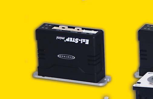
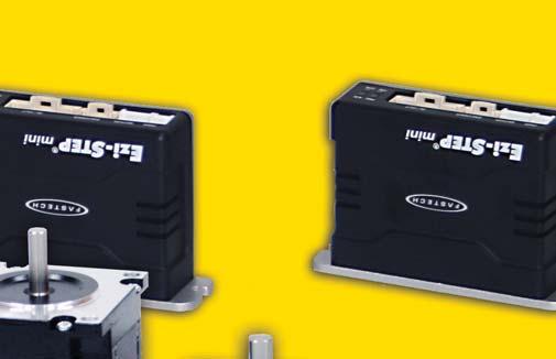
Ezi-STEP MINI Characteristics
|
|
|
- Shannon Douglas
- 5 years ago
- Views:
Transcription
1

2


 Utilizing a software damping and filtering algorithms, high speed operation is realized by the exciting angle control of a step-angle.")
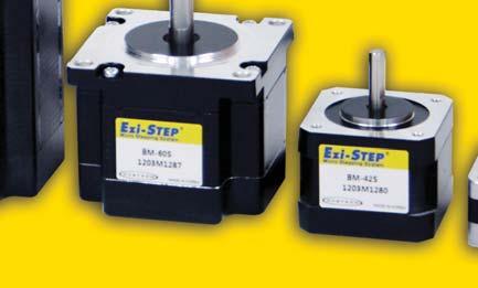
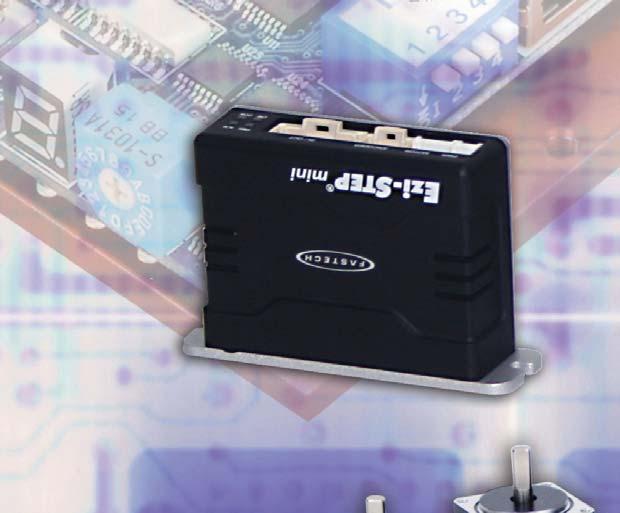
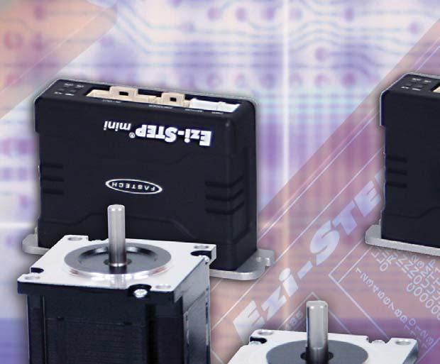
3 Ezi-STEP MINI Characteristics Ezi-STEP MINI is a micro stepping system that incorporates a motor and DSP (Digital Signal Processor) equipped drive that is integrated seamlessly together as a system. This makes it possible to incorporate many functions compared with a conventional stepping motors and drives, such as sensorless detection of loss of synchronization, smooth control over the whole velocity range, higher torque operation and no vibration at the low speed range. Ezi-STEP MINI s on-board high-performance digital signal processor and proprietary algorithms allow the Ezi-STEP MINI to operate a high speeds with unmatched precision. The unique position estimation algorithm instantaneously detects out-of-synchronization based on the rotor position of the stepping motor, which is not an easy task in a conventional stepping motor and drives (effective only over 300 rpm.) Utilizing a software damping and filtering algorithms, high speed operation is realized by the exciting angle control of a step-angle. The resolution of Ezi-STEP MINI can be selected from basic 1.8 up to (1/250). In addition, Ezi-STEP MINI generates various signals including sensorless stall detection, alarm and running signal. Ezi-STEP MINI is an economical ideal drive for vision systems, nanotech, packaging, semiconductor, pick and place, automation, laboratory testing, wood working and wherever smooth, quiet, precise, high torque operation is a requirement! 1 Sensorless Stall Detection Detecting the loss-of-synchronization with on-board DSP(patent pending) Ezi-STEP MINI can detect the loss-of-synchronization of a stepping motor without the addition of an external sensor. By monitoring the voltage, current, and back-emf signal, the on-board DSP estimates the current position of a rotor and enables it to detect the loss-of-synchronization (an impossible task for a conventional stepping motor drive), this allows for high-speed operation at 100% torque rating without loss-ofsynchronization*. *Effective only over 300 rpm Detecting area of loss-of-synchronization 3 2 Microstep and Filtering High precision Microstep function and Filtering (Patent pending) The high-performance DSP operates at step resolutions of 1.8 up to maximum (1/250 steps) and Ezi-STEP MINI adjusts PWM control signal in every 25μsec, which makes it possible for more precise current control, resulting in highprecision Microstep operation.


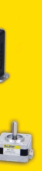
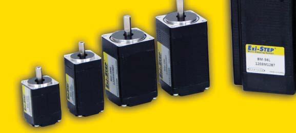
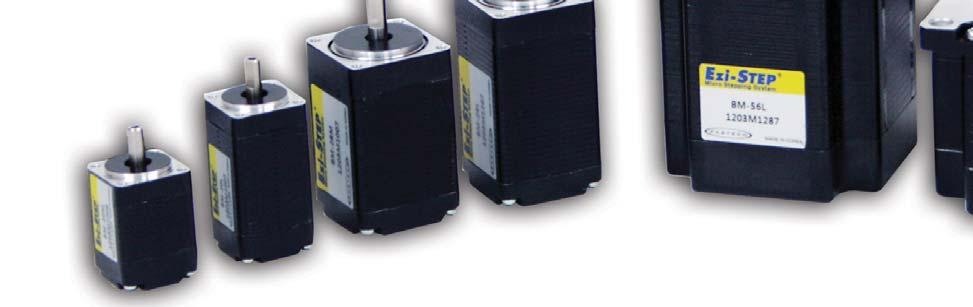
4 3 Software Damping 4 Drive Output Signal Monitoring Vibration suppression and high-speed operation (Patent pending) Vibration suppression and High-speed operation (Patent pending) Motor vibration is created by magnetic flux variations of the motor, lower current from the drive due to back-emf from the motor at high speeds and lowering of phase voltages from the drive. Ezi-STEP MINI drive detects these problems and the DSP adjusts the phase of the current according to the pole position of the motor, drastically suppressing vibration. This allows the smooth operation of the motor at high speeds. Software Damping Software Damping OFF Software Damping ON *This is real measured speed that using [pulse/rev] encoder. Ezi-STEP MINI provides loss of step, run/stop, over-current, over-heat, over-voltage, power, and motor connection alarms that can be monitored by the controller and visible by a motormounted flashing led indicator. 5 Improvement of High-Speed Driving Depending on the speed of a stepping motor, Ezi-STEP MINI automatically increases the supply voltage and prevents the torque lowering due to the low operating voltage to the motor caused by back-emf voltage, this enables high-speed operation. Additionally, the software damping algorithm minimizes the vibration and prevents the loss-of-synchronization at highspeed. Combination List Unit Part Number Motor Model Number Drive Model Number Ezi-STEP-MI-20M BM-20M EzStep-MI-20M Ezi-STEP-MI-20L BM-20L EzStep-MI-20L Part Numvering Ezi-STEP-MI-20S- Ezi-STEP-MI-25S BM-25S EzStep-MI-25S Ezi-STEP-MI-25M BM-225M EzStep-MI-25M Ezi-STEP-MI-25L BM-25L EzStep-MI-25L Ezi-STEP-MI-28S BM-28S EzStep-MI-28S Ezi-STEP-MI-28M BM-28M EzStep-MI-28M Ezi-STEP-MI-28L BM-28L EzStep-MI-28L Drive Series Type Motor Flange Size 20 : 20mm 25 : 25mm 28 : 28mm 35 : 35mm 42 : 42mm Ezi-STEP-MI-35S BM-35S EzStep-MI-35S Ezi-STEP-MI-35M BM-35M EzStep-MI-35M Ezi-STEP-MI-35L BM-35L EzStep-MI-35L Ezi-STEP-MI-35XL BM-35XL EzStep-MI-35XL Ezi-STEP-MI-42S BM-42S EzStep-MI-42S Ezi-STEP-MI-42M BM-42M EzStep-MI-42M Ezi-STEP-MI-42L BM-42L EzStep-MI-42L Ezi-STEP-MI-42XL BM-42XL EzStep-MI-42XL 4 Motor Length S : Single M : Middle L : Large XL: Extra Large Motor Type Blank : Standard L : Low Vibration H : High Speed
5 Drive Specifications Operating Condition Function I/O Signal Motor Model BM-20 series BM-25 series BM-28 series BM-35 series BM-42 series Driver Model EzStep-MI-20 series EzStep-MI-25 series EzStep-MI-28 series EzStep-MI-35 series EzStep-MI-42 series Input Voltage 24VDC ±10% Control Method Current Consumption Ambient Temperature Humidity Vib. Resist. 0.5G Rotation Speed 0~3,000rpm Resolution (P/R) Max. Input Pulse Frequency Protection Functions LED Display Closed loop control with 32bit DSP Max : 500mA (Except motor current) In Use : 0~50 In Storage : -20~70 In Use : 35~85%RH (Non-Condensing) In Storage : 10~90%RH (Non-Condensing) 500, 1000, 1600, 2000, 3200, 3600, 4000, 5000, 6400, 8000, 10000, 20000, 25000, 36000, 40000, 50000, *Default : 10, KHz (Duty 50%) Over current, Over speed, Position tracking error, Over load, Over temperature, Over regenerated voltage, Motor connect error, Encoder connect error, Motor voltage error, Inposition error, System error, ROM error, Input voltage error, Position overflow error Power, Alarm, CW Rotation, CCW Rotation STOP Current 10%~100% (Set by DIP Switch) Be setted to set value of STOP Current after 0.1 second after motor stop. *Default : 50% Pulse Input Method 1-Pulse/2-Pulse (Selectable with DIP switch) *Default : 2 pulse Rotational Direction CW/CCW (Selectable with DIP switch) *Default : CW Speed/Position Control Pulse train input Command Input Signal Alarm reset (Photocoupler input) Output Signal Alarm, Run/stop (Phhotocoupler) Drive Size [mm] 5
6 Motor Specifications 20 M O D E L UNIT BM-20M BM-20L DRIVE METHOD ---- BI-POLAR BI-POLAR NUMBER OF PHASES VOLTAGE VDC CURRENT per PHASE A RESISTANCE per PHASE Ohm INDUCTANCE per PHASE mh HOLDING TORQUE N m ROTOR INERTIA g cm WEIGHTS g LENGTH (L) mm ALLOWABLE OVERHUNG LOAD 3mm N (DISTANCE FROM END OF SHAFT) 8mm ALLOWABLE THRUST LOAD N Lower than motor weight INSULATION RESISTANCE MOhm 100min. (at 500VDC) INSULATION CLASS ---- CLASS B (130 ) OPERATING TEMPERATURE 0 to 55 Motor Dimension [mm] and Torque Characteristics 6 45 Measured Condition Motor Voltage = 24VDC Motor Current = Rated Current(Refer to Motor Specification) Drive = Ezi-STEP MINI
7 Motor Specifications 25 M O D E L UNIT BM-25S BM-25M BM-25L DRIVE METHOD ---- BI-POLAR BI-POLAR BI-POLAR NUMBER OF PHASES VOLTAGE VDC CURRENT per PHASE A RESISTANCE per PHASE Ohm INDUCTANCE per PHASE mh HOLDING TORQUE N m ROTOR INERTIA g cm WEIGHTS g LENGTH (L) mm ALLOWABLE OVERHUNG LOAD 3mm N (DISTANCE FROM END OF SHAFT) 8mm ALLOWABLE THRUST LOAD N Lower than motor weight INSULATION RESISTANCE MOhm 100min. (at 500VDC) INSULATION CLASS ---- CLASS B (130 ) OPERATING TEMPERATURE 0 to 55 Motor Dimension [mm] and Torque Characteristics BM-25 series ¹ 10² 10³ 3X10³ Measured Condition Motor Voltage = 24VDC Motor Current = Rated Current(Refer to Motor Specification) Drive = Ezi-STEP MINI
8 Motor Specifications 28 M O D E L UNIT BM-28S BM-28M BM-28L DRIVE METHOD ---- BI-POLAR BI-POLAR BI-POLAR NUMBER OF PHASES VOLTAGE VDC CURRENT per PHASE A RESISTANCE per PHASE Ohm INDUCTANCE per PHASE mh HOLDING TORQUE N m ROTOR INERTIA g cm WEIGHTS g LENGTH (L) mm ALLOWABLE OVERHUNG LOAD (DISTANCE FROM END OF SHAFT) 3mm mm N 13mm mm ALLOWABLE THRUST LOAD N Lower than motor weight INSULATION RESISTANCE MOhm 100min. (at 500VDC) INSULATION CLASS ---- CLASS B (130 ) OPERATING TEMPERATURE 0 to 55 Motor Dimension [mm] and Torque Characteristics 8 6 Measured Condition Motor Voltage = 24VDC Motor Current = Rated Current(Refer to Motor Specification) Drive = Ezi-STEP MINI
9 Motor Specifications 35 M O D E L UNIT BM-35S BM-35M BM-35L BM-35XL DRIVE METHOD ---- BI-POLAR BI-POLAR BI-POLAR BI-POLAR NUMBER OF PHASES VOLTAGE VDC CURRENT per PHASE A RESISTANCE per PHASE Ohm INDUCTANCE per PHASE mh HOLDING TORQUE N m ROTOR INERTIA g cm WEIGHTS g LENGTH (L) mm ALLOWABLE OVERHUNG LOAD (DISTANCE FROM END OF SHAFT) 3mm mm N 13mm mm ALLOWABLE THRUST LOAD N Lower than motor weight INSULATION RESISTANCE MOhm 100min. (at 500VDC) INSULATION CLASS ---- CLASS B (130 ) OPERATING TEMPERATURE 0 to 55 Motor Dimension [mm] and Torque Characteristics MOLEX (0.36) PIN NO Ø (Ø ) 0 Ø (Ø ) 8.0 (0.31) 35 (1.38) 26 ¾0.2 (1.02 ¾0.008 ) 3.3 (0.13) 6 4-M3 x 0.5 DEPTH 3MIN (DHPTH 0.118MIN) ¾ (1.02 ¾0.008) 35 (1.38) 20 ¾0.5 (0.79 ¾0.02) 2 (0.08) ``L MAX NAME PLATE BM-35 series ¹ 10² 10³ 3X10³ 60 Measured Condition Motor Voltage = 24VDC Motor Current = Rated Current(Refer to Motor Specification) Drive = Ezi-STEP MINI
10 Motor Specifications 42 M O D E L UNIT EzM-42S-A EzM-42S-B EzM-42S-C EzM-42M-A EzM-42M-B EzM-42M-C EzM-42L-A EzM-42L-B EzM-42L-C EzM-42XL-A EzM-42XL-B EzM-42XL-C DRIVE METHOD ---- BI-POLAR BI-POLAR BI-POLAR BI-POLAR NUMBER OF PHASES VOLTAGE VDC CURRENT per PHASE A RESISTANCE per PHASE Ohm INDUCTANCE per PHASE mh HOLDING TORQUE N m ROTOR INERTIA g cm WEIGHTS g LENGTH (L) mm ALLOWABLE OVERHUNG LOAD (DISTANCE FROM END OF SHAFT) 3mm mm N 13mm mm ALLOWABLE THRUST LOAD N Lower than motor weight INSULATION RESISTANCE MOhm 100min. (at 500VDC) INSULATION CLASS ---- CLASS B (130 ) OPERATING TEMPERATURE 0 to 55 Motor Dimension [mm] and Torque Characteristics 10 Measured Condition Motor Voltage = 24VDC Motor Current = Rated Current(Refer to Motor Specification) Drive = Ezi-STEP MINI


11 Setting and Operating Status monitor LED In Position Resolution Input/Output connection (CN1) Motor connection(cn3) Pulse input selection Directiaon selection Power connection(cn4) 1. Status monitor LED Indication Color Function Flash Condition PWR Green Power input Lights when power is ON Flashs when motor is Indication Free status Flash when protection function is activated (Identifiable ALM Red Alarm indication which protection mode is activated by counting the flash times) CW Yellow Motor Rotation Direction Lights when motor rotate CW direction CCW Orange Motor Rotation Direction Lights when motor rotate CCW direction Protection functions and LED flash times Times Protection Conditions 1 Over current Excessive current flowed into a motor 2 Over speed Motor speed exceeded 3000 rpm 3 Step out Abnormally motor do not followed pulsed input 5 Over temperature Internal temperature of a motor drive exceeded 55 6 Over regenerative voltage Back EMF more than 50V 7 Motor connect error Power is ON without connection of motor cable to drive 9 Motor voltage error Motor voltage is below 20V 11 System error Error occurs in drive system 12 ROM error Error occurs in Parameter storage Device(ROM) 14 Input voltage error Power source voltage is out of limited value [20V~28V] Alarm LED flash (ex: Synchronization error) Stop Current Selection Stop Current means the motor current value automatically set in 0.1 sec after motor stops. This is to prevent the overheart of a motor when the motor is under long time idling. The unit of the selection value is a percentage. Switch Position(SW1) Switch Position(SW1) STOP Current(%) STOP Current(%)
12 3. Resolution selection switch The number of pulse per revolution. Switch Position(SW1) Pulse/ Switch Position(SW1) Pulse/ Revolution Revolution , , , , , , , , , , , , , , ,000 The default factory setting is 10, Rotational direction selection switch Indication Switch Name Functions Rotational Direction Based on CW(+Dir signal) input to drive. DIR Select Switch 1 : CCW(-Direction) 0 : CW(-Direction) The default factory setting is CW(clockwise). Direction selection switch : 1 Direction selection switch : 0 5. Pulse input selection switch Indication Switch Name Functions Pulse input mode Selectable 1-Pulse input mode of 2-Pulse input mode as pulse input signal. 1P/2P Select Switch 1 : 1-Pulse mode 0 : 2-Pulse mode The default factory setting is 2-Pulse mode 2-Pulse Mode CW(Pulse) Pin CCW(Dir) Pin Rotational Direction CW CCW CW 1-Pulse Mode CCW Signal Connector(CN1) NO. Function Input/ Output 1 CW+(PULSE+) Input 2 CW-(PULSE-) Input 3 CCW+(DIR+) Input 4 CCW-(DIR-) Input 11 Alarm Output 12 Run/Stop Output 14 ALARM RESET Input 19 24VDC GND Input 20 24VDC Input Motor Connector(CN3) NO. Function 1 B 2 /B 3 /A 4 A 8. Power Connector(CN4) NO. Function 1 24VDC ±10% 2 GND


13 System Configuration Type Signal Cable Motor Cable Power Cable Standard Length - 30cm - Max. Length 20m 20m 2m 1. Cable Option 1Signal Cable Available to connect between Control System and Ezi-STEP MINI. Item Length[m] Remark CSVI-S- F CSVI-S- M Normal Cable Robot Cable is for Cable Length. The unit is 1m and Max. 20m length. 2Power Cable Available to connect between Power and Ezi-STEP MINI. Item Length[m] Remark CMNB-P- F CMNB-P- M Normal Cable Robot Cable is for Cable Length. The unit is 1m and Max. 2m length. 13 3Motor Extension Cable Available to extended connection between motor and Ezi-STEP MINI. Item Length[m] Remark CMNB-M- F CMNB-M- M Normal Cable Robot Cable is for Cable Length. The unit is 1m and Max. 20m length.
14 Connector for Cabling Motor ITEM Specification Marker Housing MOLEX Signal Connector (CN1) Terminal (AWG 26~28) MOLEX Connector VE 3M Backshell AO-008 3M Motor Connector (CN3) Housing PAP-04V-S JST` Terminal SPHD-001T-P0.5 JST Motor Side Housing R MOLEX Terminal 5556T MOLEX Housing PAP-02V-S JST Power Connector (CN4) Terminal SPHD-001T-P0.5 JST Housing R MOLEX Terminal 5556T MOLEX External Wiring Diagram Ezi-STEP-MINI 14
15 Control Signal input/output Description 1 Input signal Input signals of the drive are all photocoupler protected. The signal shows the status of internal photocouplers [ON: conduction], [OFF: Non-conduction], not displaying the voltage levels of the signal. CW(Pin:1,2), CCW(Pin:3,4) Alarm Reset (Pin:14) Servo On/Off(Pin:13) CW, CCW Input This signal can be used to receive a positioning pulse command from a user host motion controller. The user can select 1-pulse input mode or 2-pulse input mode (refer to switch No.1, SW1). The input schematic of CW, CCW is designed for 5V TTL level. When using 5V level as an input signal, the resistor Rx is not used and connect to the driver directly. When the level of input signal is more than 5V, Rx resistor is required. If the resistor is absent, the drive will be damaged! If the input signal level is 12V, Rx value is 2.2Kohm and 24V, Rx value is 4.7Kohm. Servo On/Off Input This input can be used only to adjust the position by manually moving the motor shaft from the load-side. By setting the signal [ON], the driver cuts off the power supply to the motor. Then, one can manually adjust output position. When setting the signal back to [OFF], the driver resumes the power to the motor and recovers the holding torque. When driving a motor, one needs to set the signal [OFF]. Alarm Reset Input When a protection mode has been activated, a signal to this alarm reset input cancels the Alarm output. By setting the alarm reset input signal [ON], cancel the Alarm output. Before cancel the Alarm output, have to remove the source of alarm. 2 Output signals Output signals from the driver are photocoupler protected: Alarm, In-Position and the Line Driver Outputs (encoder signal). In the case of photocoupler outputs, the signal indicates the status of internal photocouplers [ON: conduction], [OFF: Nonconduction], not displaying the voltage levels of the signal. In-Position Output In-Position signal is [ON] when positioning is completed. This signal is [ON] when the motor position error is within the value set by the switch SW4. 15 Alarm(Pin:11), In-Position(Pin:12) Encoder signal (Pin:5,6,7,8,9,10) Alarm Output The Alarm output indicates [ON] when the driver is in a normal operation. If a protection mode has been activated, it goes [OFF]. A host controller needs to detect this signal and stop sending a motor driving command. When the driver detects an abnormal operation such as overload or over current of the motor, it sets the Alarm output to [OFF], flashes the Alarm LED, disconnect the power to a motor and stops the motor simultaneously. [Caution] Only at the Alarm output port, the photocoupler isolation is in reverse. When the driver is in normal operation the Alarm output is [ON]. On the contrary when the driver is in abnormal operation that start protection mode, the Alarm output is [OFF]. Encoder signal Output The encoder signal is a line driver output. This can be used to confirm the stop position.
16 16 MEMO
17 MEMO 17
18 18 ccopyright 2010 FASTECH Co,. Ltd. All Rights Reserved. Mar 21, 2012 Rev. 01
$MPTFE -PPQ 4UFQQJOH 4ZTUFN.JOJBUVSJ[FE $PNQBDU 4J[F $MPTFE -PPQ 4ZTUFN /P (BJO 5VOJOH /P )VOUJOH )JHI 3FTPMVUJPO 'BTU 3FTQPOTF
VOUJOH )JHI 3FTPMVUJPO 'BTU 3FTQPOTF") $MPTFE -PPQ 4UFQQJOH 4ZTUFN.JOJBUVSJ[FE $PNQBDU 4J[F $MPTFE -PPQ 4ZTUFN /P (BJO 5VOJOH /P )VOUJOH )JHI 3FTPMVUJPO 'BTU 3FTQPOTF ú ú ú ú ú ú 2 2 No Gain Tuning Conventional servo systems, to ensure machine
$MPTFE -PPQ 4UFQQJOH 4ZTUFN.JOJBUVSJ[FE $PNQBDU 4J[F $MPTFE -PPQ 4ZTUFN /P (BJO 5VOJOH /P )VOUJOH )JHI 3FTPMVUJPO 'BTU 3FTQPOTF ú ú ú ú ú ú 2 2 No Gain Tuning Conventional servo systems, to ensure machine
No Gain Tuning. Hunting. Closed Loop System
 2 No Gain Tuning Conventional servo systems, to ensure machine performance, smoothness, positional error and low servo noise, require the adjustment of its servo s gains as an initial crucial step. Even
Operating Manual.
 Operating Manual www.fastech.co.kr FASTECH Co.,Ltd. Table of Contents 1. Precautions 2. Main characteristics 3. Drive Specification and Dimension 4. Motor Specification and Size 4.1 Ezi-SERVO-BT-42 Series
Fastech Co.,Ltd. Table of Contents
 Fastech Co.,Ltd. Table of Contents 2 Before operating Thank you for purchasing Ezi-STEP. For high-speed and high-precision drive of a stepping motor, Ezi-STEP is an unique drive that adopts a new control
Position Table Function. Closed Loop System. Network Based Motion Control. No Gain Tuning
 2 2 Position Table Function Position Table can be used for motion control by digital input and output signals of host controller. You can operate the motor directly by sending the position table number,
CL86T. 24~80VDC, 8.2A Peak, Closed-loop, No Tuning. Descriptions. Closed-loop. Stepper. Applications. Datasheet of the Closed-loop Stepper CL86T
 CL86T Closed-loop Stepper 24~80VDC, 8.2A Peak, Closed-loop, No Tuning Closed-loop, eliminates loss of synchronization Broader operating range higher torque and higher speed Reduced motor heating and more
ES86 Series Closed-loop Stepper Drive + Motor System (Drive+ Motor/Encoder)
") ES86 Series Closed-loop Stepper Drive + Motor System (Drive+ Motor/Encoder) Traditional stepper motor drive systems operate open loop providing position control without feedback. However, because of this,
ES86 Series Closed-loop Stepper Drive + Motor System (Drive+ Motor/Encoder) Traditional stepper motor drive systems operate open loop providing position control without feedback. However, because of this,
30-80V, 8.2A Peak, No Tuning, Nulls loss of Synchronization
 2-phase Hybrid Servo Drive 30-80V, 8.2A Peak, No Tuning, Nulls loss of Synchronization Closed-loop, eliminates loss of synchronization Broader operating range higher torque and higher speed Reduced motor
Datasheet of the MEZ Stepper Servo Drive MEZ 2D VDC, 8.2A Peak, Closed-loop, No Tuning. Version
 Datasheet of the MEZ Stepper Servo Drive MEZ D880 4-75VDC, 8.A Peak, Closed-loop, No Tuning Version 0.1.1 http://www.motionking.com Features Step and direction control Closed position loop for no loss
Datasheet of the Easy Servo Drive ES-D VAC or VDC, 8.2A Peak, Close-loop, No Tuning. Version
 Datasheet of the Easy Servo Drive ES-D1008 0-70 V or 30-100VDC, 8.A Peak, Close-loop, No Tuning Version 0.1.0 http://www.leadshine.com Features Step and direction control Closed position loop for no loss
ES86 Series Closed-loop Stepper Drive + Motor System (ES-D808 Drive+ Motor/Encoder)
") ES86 Series Closed-loop Stepper Drive + Motor System (ES-D808 Drive+ Motor/Encoder) Traditional stepper motor drive systems operate open loop providing position control without feedback. However, because
ES86 Series Closed-loop Stepper Drive + Motor System (ES-D808 Drive+ Motor/Encoder) Traditional stepper motor drive systems operate open loop providing position control without feedback. However, because
Integrated Easy Servo
 ies 1706 Integrated Easy Servo Motor + Drive + Encoder, 18 32VDC, NEMA17, 0.6Nm Features Easy servo control technology to combine advantages of open loop stepper systems and brushless servo systems Closed
ies-2309 Integrated Easy Servo
 Datasheet of the integrated easy servo motor ies-09 ies-09 Integrated Easy Servo Motor + Drive + Encoder, 0-0VDC, NEMA, 0.9Nm Features Easy servo control technology to combine advantages of open-loop stepper
Datasheet of the Easy Servo Drive ES-D VDC, 8.0A Peak, Closed-loop, No Tuning
 Datasheet of the Easy Servo Drive ES-D508 0-45VDC, 8.0A Peak, Closed-loop, No Tuning Version 1. http://www.leadshine.com Features Step and direction control Closed position loop for no loss of movement
3DM phase Digital Stepper Drive
 3DM2283 3-phase Digital Stepper Drive 150-220VAC, 0.5-8.2A peak, Auto-configuration, Low Noise Anti-Resonance provides optimal torque and nulls mid-range instability Motor auto-identification and parameter
HBS Series Hybrid Servos
 Hybrid Servos 46 Hybrid Servos From the stepper and servo, but surpass them in many applications! HBS Series Hybrid Servos Closed-loop, eliminates loss of synchronization The HBS series use an encoder
Technical data. General specifications. Measurement range min max. 360
 Model Number Features Very small housing High climatic resistance 12 Bit singleturn Analog output Surge and reverse polarity protection Description This absolute rotary encoder with internal magnetic sampling
Two-phase Digital Stepper Motor Driver SD Low Vibration Low Noise Low Power. Characteristics. Performance Index. Product Codes:
 Two-phase Digital Stepper Motor Driver SD-20403 Product Codes: 001700 Low Vibration Low Noise Low Power Characteristics 32-bit DSP digital control mode Low vibration. low noise. low power Flexible micro-stepping,
Closed Loop Stepping System with Network based Motion Controller
 Closed Loop Stepping System with Network based Motion Controller 2 Position Table Function Position Table is used for motion control by digital input and output signals of host controller. You can operate
Driver specifications Motor Specifications P.57
 specifications Motor Specifications P. General Specifications Unipolar Bipolar Model number USDP BSDP Input source DC V/ V Source current A Basic specifications Environment Protection class Operation environment
Integrated Servo Motor UCS57
 Integrated Servo Motor Introduction is a new generation of high performance digital integrated servo drive motor, which is a series of low voltage AC servo products integrated with AC servo motor and drive
DMX-K-DRV-23 Integrated Step Motor Driver & Basic Controller
 DMX-K-DRV-23 Integrated Step Motor Driver & Basic Controller DMX-K-DRV-23 Manual - 1 - rev 1.35 COPYRIGHT 2013 ARCUS, ALL RIGHTS RESERVED First edition, June 2007 ARCUS TECHNOLOGY copyrights this document.
Integrated servo motor
 R88E-AECT@, R88S-EAD@ Integrated servo motor Motor and drive integrated for space optimization Wide range of motors from 2.55 Nm to 25 Nm 3000 rpm rated speed Peak torque 300% of rated torque IP65 protection
PKG-171-MBC25-PS-CBL System Diagram and Specifications
 PKG-171-MBC25-PS-CBL System Diagram and Specifications Included Components: 17Y102S-LW4-MS Stepper Motor MBC25081TB Stepper Driver PSAM24V2.7A Power Supply CBL-20AWG-04C-010-MS Motor Cable CBL-AA4366 Power
Compact Actuator DRL Series
 Introduction Precision Rack & Pinion Linear Linear Actuators Heads DRL LH Accessories Before Using a Linear Motion System Compact Actuator DRL Series Additional Information Technical Reference F-1 General
Brushless DC Motor Systems AXH Series
 Brushless DC Systems AXH Series The AXH Series combines a compact, brushless DC speed control motor and 24 VDC board-level driver. These systems provide space savings and high power output, and are easy
DCS810 Brushed DC Servo Drive
 Datasheet of Brushed DC Servo Drive DCS810 DCS810 Brushed DC Servo Drive 18-80VDC, 0-20A, 20-400W Based on DSP control technology and high smooth servo control algorithm Parameter visible tuning tools,
Logosol Intelligent Hall-Servo Drive LS-173U Doc # / Rev. C, 02/12/2008
 Features Specially designed for control of brushless motors without encoder Hall-Servo and Encoder-Servo control modes Motors supported: - Brushless 60/120 commutated (AC) - Brush-commutated (DC) Up to
DCS Series Brush DC Servo Drive. Datasheet
 DCS Series Brush DC Servo Drive Datasheet Version DCS-2014-01 http://www.primopal.com DCS series Brush DC Servo Drives Description PrimoPal s DCS series Brush DC Servo Drive are fully digital brushed servo
Diameter ø50mm Shaft type Absolute Multi-turn Rotary Encoder
 Dia ø50mm Shaft type Absolute Multi-turn otary Encoder Features Compact size of dia ø50mm Parallel data / SSI data transmission type Total 23bit resolution(8388608 divisions) of 10bit single-turn(1024
Connection and Operation
 Connection and Operation LED Display Control Module Motor Regeneration Unit Terminals Power Connection Terminals Protective Earth Terminal Internal Potentiometer Acceleration Time Potentiometer Deceleration
10.9. Serial communication parameters Motor parameters Paramters handling Status monitor
 Contents 1. Introduction... 4 1.1. About power supply for AU9290... 4 1.2. About applicable stepping motors... 4 1.3. About setting and storing of parameters... 5 1.4. About optional functions... 5 1.5.
Low Cost, Small Package, 120VAC Microstepping Drive
 Catalog 8-4/USA E-AC Low Cost, Small Package, 12VAC Microstepping Drive Compumotor's new E-AC is a low-cost, high-performance, high-reliability microstepping drive in a small package. The design of the
BLuAC5 Brushless Universal Servo Amplifier
 BLuAC5 Brushless Universal Servo Amplifier Description The BLu Series servo drives provide compact, reliable solutions for a wide range of motion applications in a variety of industries. BLu Series drives
DMX-K-DRV-17 Integrated Step Motor Driver & Basic Controller
 DMX-K-DRV-17 Integrated Step Motor Driver & Basic Controller DMX-K-DRV-17 Manual - 1 - rev 1.35 COPYRIGHT 2015 ARCUS, ALL RIGHTS RESERVED First edition, June 2007 ARCUS TECHNOLOGY copyrights this document.
Contents. USER MANUAL NI ISM-7400 Integrated Stepper
 USER MANUAL NI ISM-7400 Integrated Stepper This manual describes the NI ISM-7400 integrated stepper. It describes electrical and mechanical characteristics of the devices, as well as I/O functionality.
Step Motor Driver SMD73 and SMD A RMS and 18-48VDC
 Step Motor Driver SMD73 and SMD74. 03 A RMS and 1848VDC Step Motor Driver SMD73 and SMD74 are a miniature driver that measures only 52.4x52.4 mm and is ideal for direct mounting onto a step motor. It fits
Motor Drives & Controllers
 Motor Drives & Controllers For the past 20 years, FORMOSA MOTORS is well known for pursuing high technology motors in Taiwan. To make customer s requirements satisfatisory & perfect We supply customers
Hardware Manual. STR4 & STR8 Step Motor Drives
 Hardware Manual STR4 & STR8 Step Motor Drives 92-3J 92-3J Contents Introduction... 3 Features... 3 Block Diagram... 4 Getting Started... 5 Mounting the Drive... 6 Connecting the Power Supply... 6 Drive
Bholanath. User s Manual. Precision Engineering Pvt.Ltd. BHSSD Step Servo Driver. Note:-
 Bholanath Precision Engineering Pvt.Ltd. User s Manual Step Servo - BHSS - 750 W BHSSD Step Servo Driver Note:- Step servo drive & motor are matched pair with BH-75Vac power supply Email : support@bholanath.in
Servo Motor Driver. 4. Specifications: Digital Driver Model ACS806. Digital Technology, max. 80 V DC / 6.0 A, W. 1. Product Description:
 Digital Driver Model ACS806 Digital Technology, max. 80 V DC / 6.0 A, 50 400 W 1. Product Description: Leadshine's fully digital AC servo drive ACS806 is developed with 32-bit DSP based on advanced control
BLuAC5 Brushless Universal Servo Amplifier
 BLuAC5 Brushless Universal Servo Amplifier Description The BLu Series servo drives provide compact, reliable solutions for a wide range of motion applications in a variety of industries. BLu Series drives
UMK M A A. RoHS-Compliant. 2-Phase Stepping Motor and Driver Package. Features. Product Number Code. Product Line
 RoHS-Compliant Stepping Motor and Package UMK Series Additional Information Technical reference Page F- The UMK Series is a -phase stepping motor (resolution: per rotation) with easy-handling AC input
Technical Document. for the. CB 016N6 Driver Card
 Technical Document for the CB 06N6 Driver Card Contents Introduction 3 Page New functions 3 3 Dimensions 3 4 I/O Interface 4 5 Connectors 4-5 6 Switches 5-6 7 Potentiometers 7 8 LEDs and Error Indications
Connection and Operation
 Connection and Operation Names and Functions of Parts 4 1 Monitor Display LED Indicators DG60 1 5 Motor Connector Power Connector Indication Color Function When Activated OPERATI Green Power Supply Indication
:PMM-BA ø 60 ø 86 ø 106
 Pulse I/ (AC power input) The -Phase Stepping Driver PMM-BA-- PMM-BA-- ACV/V -step/half-step ( x division) ( x divisions) Applicable motor ø ø ø Characteristics lexible These drivers can drive various
RoHS Directive-Compliant Compact Linear Actuators DRL Series. Features
 Motorized ctuators RoHS Directive-Compliant Compact Linear ctuators DRL Series In the compact linear actuator DRL Series, the drive mechanism adopts a -phase stepping motor with ball screw. This series
DM9082 Closed Loop Stepping System
 DM9082 Closed Loop Stepping System 1. Introduction Descriptions DM9082 is a new generation hybrid servo driver, it uses the 32-bit DSP processor, the internal integrates the technology of the anti-resonance,
LSM&DSD Brushless Servo Drive Package
 LSM&DSD Brushless Servo Drive Package Descriptions LSM&DSD brushless servo drive package consists of one of LSM60 brushless servo motors and DSD806 brushless servo drive, offering high performance with
PMM-BA PMM-BA AC 100 V/115 V Full-step/half-step (500 x 1 divisions) (500 x 2 divisions)
 (500 x 2 divisions)") Pulse I/ (AC power input) The -Phase Stepping Driver - PMM-BA-- AC V/ V ull-step/half-step ( x divisions) ( x divisions) Applicable motors ø ø Characteristics High-speed type These drivers are high-speed
Pulse I/ (AC power input) The -Phase Stepping Driver - PMM-BA-- AC V/ V ull-step/half-step ( x divisions) ( x divisions) Applicable motors ø ø Characteristics High-speed type These drivers are high-speed
New Servo Concept: Junma
 New Servo Concept: Junma Junma uses the world s premier servo technology to provide unmatched performance with a quick and efficient setup. This totally new plug and play design concept requires no parameter
L E C T U R E R, E L E C T R I C A L A N D M I C R O E L E C T R O N I C E N G I N E E R I N G
 P R O F. S L A C K L E C T U R E R, E L E C T R I C A L A N D M I C R O E L E C T R O N I C E N G I N E E R I N G G B S E E E @ R I T. E D U B L D I N G 9, O F F I C E 0 9-3 1 8 9 ( 5 8 5 ) 4 7 5-5 1 0
PKG-341-MLA-CBL System Diagram and Specifications
 PKG-341-MLA-CBL System Diagram and Specifications 600 34Y112S-LW8, MLA10641, Div by 16, 120VAC, Series 400 Included Components: 540 360 34Y112S-LW8-MS MLA10641 CBL-18AWG-04C-010-MS PWR-10EMC1 LIN-AA4254
Engineering Data AC Servo Drive HA-680
 Engineering Data AC Servo Drive HA-680 QUICKLINK www.harmonicdrive.de/1110 SAFETY GUIDE For FHA series, RSF series, HA series Read this manual thoroughly before designing the application, installation,
PKG-232-MBC12-PS-CBL System Diagram and Specifications
 PKG-232-MBC12-PS-CBL System Diagram and Specifications Included Components: 23Y206S-LW8-MS Stepper Motor MBC12101 Stepper Driver PSA80V4A-1 Power Supply CBL-18AWG-04C-010-MS Motor Cable WIR-1007-18-YEL
SilverMax Datasheet. QuickSilver Controls, Inc. NEMA 23 Servomotors.
 SilverMax Datasheet NEMA 23 Servomotors QuickSilver Controls, Inc. www.quicksilvercontrols.com SilverMax Datasheet - NEMA 23 Servomotors 23 Frame Sizes: 23-3, 23-5, 23H-1, 23H-3, 23H-5 / Series: E, E3,
RoHS-Compliant 2-Phase Stepping Motor and Driver Package RBK Series. Features. The RBK Series is a motor and driver package
 Stepping Motors RoHS-Compliant Stepping Motor and Package RBK Series dditional Information Technical reference Page F-1 Safety standards Page G- The RBK Series is a motor and driver package (Terminal box
RoHS-Compliant 2-Phase Stepping Motor and Driver Package RBK Series. Features
 Stepping s RoHS-Compliant -Phase Stepping and Package RBK Series dditional Information Technical reference Page F- Safety standards Page G- The RBK Series is a motor and driver package consisting of a
5-Phase Stepping Motor and Driver Package CSK Series
 Stepping s -Phase Stepping and Package CSK Series Additional Information Technical Reference F- General Information G- Introduction AS AS PLUS ASC RK CFK CSK PMC UMK CSK PKPV PK UIG EMP EMP SG8J SMK Accessories
Driver. 3 Extension Cables ( Page E-155)
") Motorized ctuators System Configuration Not supplied DRS Series Compact Linear ctuator ccessories (Sold separately) Mounting Plates ( Page E-54) Limit Sensor (Connected by the customer) 2 DIN Rail Mounting
Motorized ctuators System Configuration Not supplied DRS Series Compact Linear ctuator ccessories (Sold separately) Mounting Plates ( Page E-54) Limit Sensor (Connected by the customer) 2 DIN Rail Mounting
5-Phase Stepping Motor and Driver Package CSK Series
 Stepping s -Phase Stepping and Package CSK Series Additional Information Technical Reference F- General Information G- Introduction AS AS PLUS ASC RK CFK CSK PMC UMK CSK PKPV PK UIG EMP EMP SG83J SMK Accessories
Logosol AC/DC Servo Amplifier LS-57P
 Features Motors supported: - Panasonic A or S series - Brushless 60 /120 commutated - Brush-commutated 18 to 180VDC single power supply Up to 20A peak / 12A continuous current Selectable modes of operation:
S, SX & SXF Series S, SX & SXF. Packaged. Packaged Microstepping Systems. The X Series... An Indexer and Drive
 Catalog 8-2/US S, SX & SXF Systems The S Family of drives and drive/indexer systems are standalone, packaged microstepping systems. Designed for reliability, the S step and direction input drive, the SX
5-Phase Stepping Motor and Microstep Driver Package
 ORIENTAL MOTOR GENERAL CATALOGUE Motor and Microstep Driver Package RFK Features B-154 Specifications B-157 Speed - Torque Characteristics B-158 Dimensions B-159 List of motor and Driver Combinations B-16
The motors are described by the following numbering system: D 500 ppr encoder 1 E 1,000 ppr encoder 1 H Hall-effect only R resolver
 OEM77X 3 Specifications C H A P T E R 3 Specifications Complete specifications for the OEM77X Drive and Parker Compumotor SM, NeoMetric, and J Series motors are listed in this chapter. The motors are described
Servo Amplifier PMA 90 / 180
 Features Motors supported: - Brushless DC 60 /120 commutated - Brushed DC - Printed Armature DC 18 to 180VDC single power supply Up to 20A peak / 12A continuous current Selectable modes of operation: -
ORIENTAL MOTOR CATALOG
 ORIENTAL MOTOR CATALOG -PHASE HIGH-TORQUE STEPPING MOTOR AND DRIVER PACKAGE UPK W Series Features B- Product Line B- Standard Type, High-Speed Type B-8 Geared Type B-8 List of and Combinations B- Wiring
GE FANUC Spares. GE Fanuc Automation. Stepping Motor Cube with Pulse and Direction Interface. Programmable Control Products.
 GE Fanuc Automation Programmable Control Products Stepping Motor Cube with Pulse and Direction Interface User s Manual July 2002 GE FANUC Spares Warnings, Cautions, and Notes as Used in this Publication
Single-phase or three phase AC220V (-15% ~ +10%) 50 ~ 60Hz
 50 ~ 60Hz") KT270-H Servo Drive Features: The use of DSP ( digital signal processor ) chip, greatly accelerating the speed of data acquisition and processing, the motor running with good performance. Application of
KT270-H Servo Drive Features: The use of DSP ( digital signal processor ) chip, greatly accelerating the speed of data acquisition and processing, the motor running with good performance. Application of
2-Phase Stepping Motor Driver with Built-in Indexer UI2120G
 -Phase Stepping Motor Driver with Built-in Indexer UI10G Additional Information Technical Reference F-1 General Information G-1 Introduction AS AS PLUS ASC RK CFK CSK PMC UMK CSK PK/PV PK UI10G EMP01 EMP0
ST5-S ST10-S Rev. A1
 ST ST5-S ST1-S 92-27 Rev. A1 92-27 Rev. A1 ST5/1-S Hardware manual Table Of Contents Contents Introduction... 3 Features... 3 Block Diagrams... 4 Getting Started... 5 Connecting to the PC using RS-232...
DynaDrive INFORMATION MANUAL SDFP(S)
") DynaDrive INFORMATION MANUAL SDFP(S)1525-17 SERVO DYNAMICS CORP. 28231 Avenue Crocker, Santa Clarita, CA. 91355 (818) 700-8600 Fax (818) 718-6719 www.servodynamics.com INDEX Page INTRODUCTION 2 ELECTRICAL
DynaDrive INFORMATION MANUAL SDFP(S)1525-17 SERVO DYNAMICS CORP. 28231 Avenue Crocker, Santa Clarita, CA. 91355 (818) 700-8600 Fax (818) 718-6719 www.servodynamics.com INDEX Page INTRODUCTION 2 ELECTRICAL
TETRA COMPACT LOW VOLTAGE BRUSHLESS SERVOMOTORS
 TETRA COMPACT LOW VOLTAGE BRUSHLESS SERVOMOTORS BRUSHLESS TECHNOLOGY FEATURES AND BENEFITS Synchronous brushless servomotor, permanently excited Rated output power from 60W to 800W Maximum servomotor speed
Upgrading from Stepper to Servo
 Upgrading from Stepper to Servo Switching to Servos Provides Benefits, Here s How to Reduce the Cost and Challenges Byline: Scott Carlberg, Motion Product Marketing Manager, Yaskawa America, Inc. The customers
Harmonic Drive Actuator. D C S e r v o S y s t e m s. P r e c i s i o n G e a r i n g & M o t i o n C o n t r o l. RH Mini Series RHS and RFS Series
 D C S e r v o S y s t e m s RH Mini Series RHS and RFS Series Total Motion Control Harmonic Drive Actuator P r e c i s i o n G e a r i n g & M o t i o n C o n t r o l Precision Gearing & Motion Control
Incremental encoders Redundant sensing, isolated blind hollow shaft ø mm, cone shaft ø17 mm pulses per revolution
 Features Robust, compact housing Two bearings with large distance, one at each end High shaft load up to 450 N Shock resistant up to 250 g Shaft insulation up to 2.8 kv Highest operating speed 10000 rpm
815-BR SERVO AMPLIFIER FOR BRUSH SERVOMOTORS
 815-BR SERVO AMPLIFIER FOR BRUSH SERVOMOTORS USER GUIDE September 2004 Important Notice This document is subject to the following conditions and restrictions: This document contains proprietary information
SV2Dx Servo Drives SV200 Servo Drives for DC-Powered Applications
 24 to 60 VDC input 10 A cont., 20 A peak output current Compact size for multi-axis applications Ideal for OEMs Designed for use with J Series motors Wide range of control options 8 regular digital inputs,
Manual. ihss57-xx. Integrate Stepper Servo Motor.
 ihss57-xx Integrate Stepper Servo Motor Manual Shenzhen Just Motion Control Electro-mechanics Co., Ltd TEL:+86-0755-26509689 FAX:+86-0755-26509289 www.jmc-motion.com Email:jmk@jmc-motion.com Address: Floor2,
SGMMV. Rotary Servomotors SGMMV - A1 A 2 A 2 1. Model Designations. 6th. 5th digit. 1st+2nd digits. 7th digit. 4th digit. 3rd digit.
 Rotary s Model Designations - mini Series st+nd digits 3rd digit th digit th digit 6th digit 7th digit st+nd digits Rated Output th digit Design Revision Order 7th digit Options Code Code Code B3 3.3 W
DYN2 Series D M M AC SERVO DRIVE LOW VOLTAGE TYPE A - GENERAL PURPOSE PULSE/ANALOG. Dynamic Motor Motion Technology Corporation
 D M M Dynamic Motor Motion Technology Corporation AC SERVO DRIVE DYN2 Series LOW VOLTAGE TYPE A - GENERAL PURPOSE PULSE/ANALOG Published in Canada Low Voltage AC Servo Technique for the Future 2 FEATURES
Servo Motors B-9. Overview. Tuning-Free NX. Tuning-Free NX Series. Servo Motors. Accessories. Page. NX Series B-10 B-9
 Servo Motors B-9 Overview NX Servo Motors Accessories Page B-1 B-9 B-1 Servo Motor and Driver Package Technical reference Page H-1 Regulations & Standards Page I-2 For detailed
Stepper Motor Driver CW8060
 Stepper Motor Driver CW8060 CW8060 1. Introduction Descriptions The CW8060 driver is a cost-effective and high performance stepping driver. The design is based on an advanced control technology. It applies
Logosol AC/DC Intelligent Servo Drive for Coordinated Control LS-174WP
 Features Motors supported: - Panasonic A and S series - Brushless 60/120 commutated - Brush-commutated (DC) motors Up to 20A peak, 12A continuous output current 12 to 90VDC power supply Separate motor
General-Purpose AC Servo. MELSERVO-JE Servo amplifier INSTRUCTION MANUAL (TROUBLE SHOOTING)
") General-Purpose AC Servo MELSERVO-JE Servo amplifier INSTRUCTION MANUAL (TROUBLE SHOOTING) D Safety Instructions Please read the instructions carefully before using the equipment. To use the equipment
General-Purpose AC Servo MELSERVO-JE Servo amplifier INSTRUCTION MANUAL (TROUBLE SHOOTING) D Safety Instructions Please read the instructions carefully before using the equipment. To use the equipment
DeviceCraft Revision #1 11/29/2010
 DeviceCraft Revision #1 11/29/2010 DC Wiper Motor H-Bridge Servo / Speed Controller P/N 1020 Features: Dip Switch selectable mode of operation Both PID servo or speed controller Forward/Reverse operation
TRD-N/NH Series Incremental Encoders
 /N Series Encoders TRD-K TRD-K A TRD-GK TRD-J /N TRD-2E TRD-S/S Features Shaft and ollow Shaft type are available. Compact body with 5mm diameter and 35mm depth. Wide range of resolution from 1 to 2,5P/R.
General-Purpose AC Servo. MELSERVO-JE Servo amplifier INSTRUCTION MANUAL (TROUBLE SHOOTING)
") General-Purpose AC Servo MELSERVO-JE Servo amplifier INSTRUCTION MANUAL (TROUBLE SHOOTING) F Safety Instructions Please read the instructions carefully before using the equipment. To use the equipment
General-Purpose AC Servo MELSERVO-JE Servo amplifier INSTRUCTION MANUAL (TROUBLE SHOOTING) F Safety Instructions Please read the instructions carefully before using the equipment. To use the equipment
Vert-X 27E - 5V / % Ub. Applications Harvesting machine Fork lift Hydraulic pump
 Sensor principle MH-C MH-C2 Electrical data Measuring range 0... 360 0... 360 Indep. linearitiy (without misalignment) % of meas. range ±0.3 ±0.3 Indep. linearitiy (with allowed misalignment @ 360 ) %
Shenzhen Alpha Inverter Co., Ltd. AS100 AC Servo Drive
 Shenzhen Alpha Inverter Co., Ltd. AS100 AC Servo Drive 1 Feature AS100 series AC servo system consists of the all-digital AC servo drive and the permanent-magnet servo motor. AS100 AC servo drive adopts
Express Delivery. Axial. Connection
 HIGH RESOLUTION INCREMENTAL SOLID SHAFT ENCODER FOR INDUSTRIAL APPLICATIONS Resolution up to 50.000 pulses per turn External diameter 58 mm Shaft from Ø 6 to 12 mm Protection class IP67 according to DIN
1525-BRS INFORMATION MANUAL SERV O D YN A M ICS. D y n ad r iv e Ave Crocker Suite 10 Valencia, CA
 28231 Ave Crocker Suite 10 Valencia, CA 91355 818-700-8600 Servodynamics.com INFORMATION MANUAL 1525-BRS SERV O D YN A M ICS U SA www.servodynamics.com D y n ad r iv e Bru sh INDEX Page INTRODUCTION 2
TRD-J Series Incremental Encoders
 Series Incremental Encoders Features mm thick shaft and ø5 mm body Vibration and shock resistant metal slit plate durable at 1, P/R Operating voltage ranging from 4.75 to 3 VDC Totem-pole output facilitating
3Specifications CHAPTER THREE IN THIS CHAPTER
 CHAPTER THREE 3Specifications IN THIS CHAPTER Drive Specifications SM and NeoMetric Motor Specifications SM and NeoMetric Motor / Curves SM and NeoMetric Motor Dimensions SM and NeoMetric Encoder Specifications
Encoder - Absolut 2RMHF-SSI
 Absolute Encoder: Ø24 mm Hollow Shaft: Ø3 mm to ¼ Inch Singleturn or Multiturn SSI Interface Binary or Gray Code Preset of Zero Position Choice of Counting Direction IP-Rating: IP64 or IP67 Mechanical
43000 Series: Size 17 Single Stack Stepper Motor Linear Actuator
 HAYD: 2 756 744 4 Series: Single Stack Stepper Motor Linear Actuator Haydon 4 Series hybrid linear actuators are our best selling compact hybrid motors. Single Stack Captive Shaft These top selling designs
(For Rotary Servomotors)
") MECHATROLINK-III Communications Reference SERVOPACKs SGDV- E2 (For Rotary Servomotors) Designations S G D V - 2R9 E 2 A 002 00 0 v Series SGDV SERVOPACKs with DC Power Input st+2nd+ 3rd digits 4th digit
MECHATROLINK-III Communications Reference SERVOPACKs SGDV- E2 (For Rotary Servomotors) Designations S G D V - 2R9 E 2 A 002 00 0 v Series SGDV SERVOPACKs with DC Power Input st+2nd+ 3rd digits 4th digit
Dynamo Brushless DC Motor and GreenDriveTM Manual
 Dynamo Brushless DC Motor and GreenDriveTM Manual This manual was developed as a guide for use by FIRST Robotics Teams using Controller Part Number 840205-000 in conjunction with the Nidec Dynamo BLDC
Supply voltage Output configuration Resolution (P/R) Model 12 to 24 VDC Complementary output 100, 200, 360, 500, or 600 E6F-CWZ5G 1,000
 Model 12 to 24 VDC Complementary output 100, 200, 360, 500, or 600 E6F-CWZ5G 1,000") Incremental 60-mm-dia. Rotary Encoder E6F-C The Strongest Shaft for Tough Jobs The strongest shaft of any OMRON Incremental Encoder (120 N in the radial direction and 50 N in the thrust direction). Water-
Incremental 60-mm-dia. Rotary Encoder E6F-C The Strongest Shaft for Tough Jobs The strongest shaft of any OMRON Incremental Encoder (120 N in the radial direction and 50 N in the thrust direction). Water-