Offset Waveguide Transmission Measurements
|
|
|
- Duane Potter
- 6 years ago
- Views:
Transcription
1 NASA Technical Memorandum Offset Waveguide Transmission Measurements Robin L. Cravey Langley Research Center, Hampton, Virginia May 1997 National Aeronautics and Space Administration Langley Research Center Hampton, Virginia
2 Abstract Transmission loss measurements in S-band waveguide due to waveguide section misalignment have been performed in the Electromagnetic Properties Measurement Laboratory in NASA Langley s Electromagnetics Research Branch. These measurements were performed in support of the Hydrostar program, to determine the feasibility of using deployable waveguide sections in a large space radiometer. Low losses are essential for radiometer applications; these measurements were conducted in order to determine what misalignment tolerances were acceptable for such a deployable structure. 1
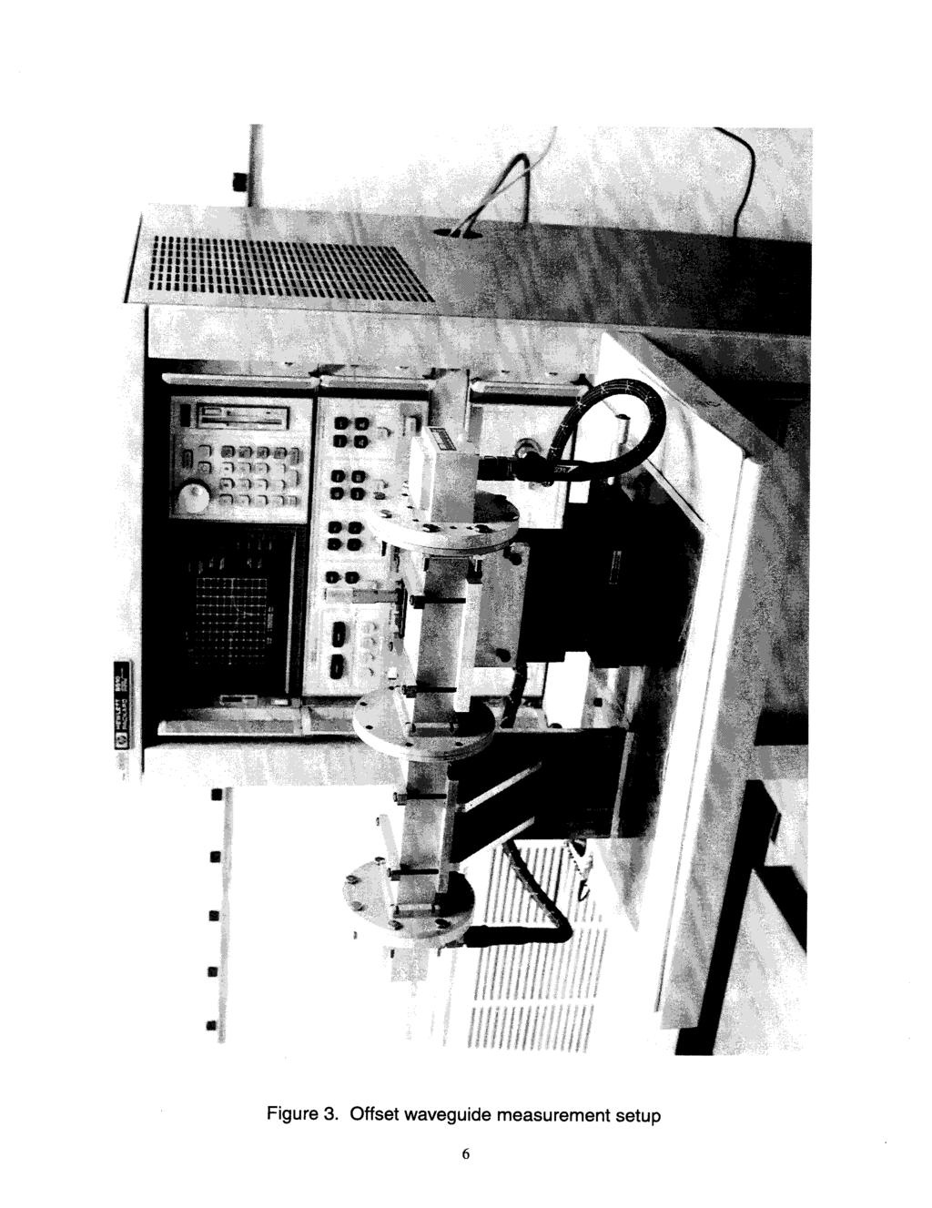
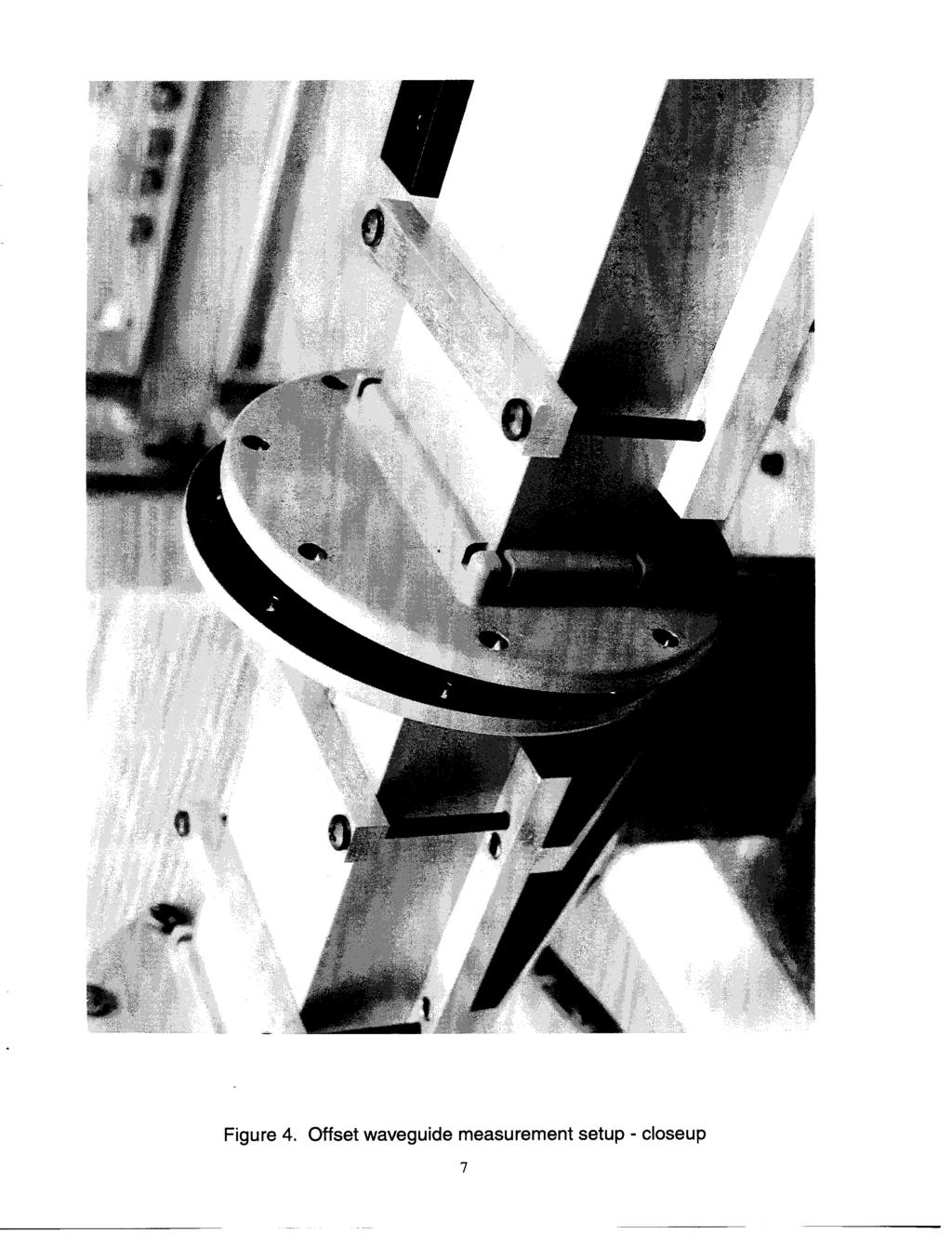
3 Introduction This report describes measurements to determine transmission losses in S-band ( GHz) waveguide sections due to misalignment of the sections relative to each other. The experiments were performed in support of the Hydrostar program, to determine the feasibility of using deployable waveguide sections in a large space radiometer. The waveguide sections would possibly be hinged and folded for launch, then deployed in space to form long sections of waveguide [ref. 1]. Since very low losses are required for radiometer applications, the effects of potential misalignment after deployment of the waveguide sections may be significant. These measurements were performed in the Electromagnetic Properties Measurement Laboratory [ref. 2] in the Electromagnetics Research Branch. Measurement Setup The measurement setup consists of a waveguide offset fixture (described below) connected to the two ports of a Hewlett-Packard 8510C network analyzer by coaxial cables and coax-to-waveguide transitions (see fig. 1). The waveguide offset fixture is a stand which clamps two pieces of S-band waveguide, each 8.0 inches long. One piece of waveguide is held fixed, while the position of the other piece of waveguide can be adjusted in three directions independently using micrometer adjustments (see fig. 2). The maximum offset in each direction is 0.5 inches. The measurement setup is shown photographically in Figures 3 and 4. Procedure Before the measurements were done, a full two-port calibration was done to the reference planes shown in Figure 1 using a standard S-band waveguide calibration kit. The waveguide offset fixture was then inserted between the coax-to-waveguide adapters between the calibration planes. The waveguide sections were set to the zero offset (aligned) positions and transmission measurements were made in several configurations. The aligned measurement configurations were: waveguide flanges bolted together; waveguide flanges loosely bolted together (bolts in place but not 2
4 tightened); waveguide flanges not bolted but clamped together with C-clamps at top and bottom of flanges; and, waveguide flanges not bolted or clamped. The moveable waveguide section was then displaced relative to the fixed section along one axis at a time in increments of 0.025, with S-parameter data (reflection and transmission coefficients) being recorded at each increment (see fig. 2 for a definition of the axes). For the x- and y-offset data, two data files were recorded for each position: one in which the flanges were clamped together at top and bottom using C-clamps, and another in which the flanges were held together only by the spring tension in the fixture. Results were also recorded for cases in which the x- and y-axes were offset equal amounts for zero z-offset, and also for cases in which the x-, y-, and z-axes were all offset equal amounts. Results The amount of data which was taken in this study precludes plotting all the data in this report, so a representative sample has been chosen. The first plot (fig. 5) shows the transmission coefficient (S21) for various aligned cases. This plot is included in order to demonstrate the transmission loss which occurs when the flanges of the waveguide sections are not bolted tightly together, even though they are aligned. The transmission coefficients given in this plot have been normalized to the transmission coefficient for the tightly bolted case in order to remove any effects from the connections between the coax-to-waveguide adapters and the waveguide sections (at the reference planes). It can be noted from this plot that the case in which the flanges were clamped together instead of tightly bolted resulted in only a small reduction in the transmission through the waveguide sections. This clamped, aligned case is used as the reference case for all the other plots shown here. The x- and y-offset cases which are shown are the measurements which were performed with the flanges clamped together. This is in order to eliminate leakage which could occur if the flanges are not tightly in contact with each other, so that the reductions in transmission should be due only to the misalignment. Obviously, for the waveguide sections offset in the z-direction relative to each other, the flanges could not be clamped together. 3
5 Figures 6 and 7 show the normalized transmission coefficients for the cases when the waveguide sections are misaligned in the x- and y-directions, respectively. Figure 8 shows the normalized transmission coefficients for simultaneous, equal offsets in the x- and y-directions. Figure 9 gives results for offsets in the z-directions. Figure 10 gives results for simultaneous, equal offsets in x-, y-, and z-directions. For each of these cases, two plots are shown: the first is a plot including a larger range in the offset to show the overall trend of the reduction in transmission due to the offset; the second is a plot showing the first few offset cases on an expanded scale for more detail. Conclusions This study has demonstrated the measured reduction in transmission through waveguide sections which are misaligned in various directions. For x-offsets alone, the transmission reductions are seen to be less than 0.05 db for offsets up to 0.25 inches. For y-offsets alone, transmission reductions of up to about 0.1 db are observed for offsets up to 0.25 inches. For both x- and y-offsets, the transmission reductions are seen to be less than 0.05 db for offsets up to 0.25 inches, and in fact for some frequencies a tuning effect seems to be occurring, as the normalized transmission coefficient is greater than 0 db. For the cases which involve z-offsets, quite large transmission losses are observed, especially over a narrow frequency range whose center frequency decreases as the gap in the z-direction is increased. References [1]. Schroeder, Bailey, Harrington, Kendall, and Campbell, Design Studies of Large Aperture, High-Resolution Earth Science Microwave Radiometers Compatible With Small Launch Vehicles, NASA Technical Paper 3469, September [2]. Cravey, Tiemsin, Bussell, Dudley, Dielectric Property Measurements in the Electromagnetic Properties Measurement Laboratory, NASA Technical Memorandum #110147, April
6 Port 1 Port 2 S-band waveguide offset fixture Calibration planes Coax-to-waveguide adapters Figure 1. Offset waveguide setup y x z Fixed waveguide section Moveable waveguide section Figure 2. Definition of coordinate system 5
7
8
9 0.1 Magnitude (S21/s21 ref) (db) Clamped Loosely bolted Spring tension only -0.4 Figure 5. Aligned case 8
10 0.10 Magnitude (S21 / S21 ref) (db) Figure 6(a). x-offset cases,.05 to.5, every.05 Magnitude (S21 / S21 ref) (db) " offset.10" offset.15" offset.20" offset.25" offset Figure 6(b). x-offset cases,.05 to.25, every.05 9
11 Magnitude(S21 / S21 ref) (db) Figure 7(a). y-offset cases,.05 to.5 offsets, every.05 Magnitude(S21 / S21 ref) (db) " offset.10" offset.15" offset.20" offset.25" offset Figure 7(b). y-offset cases,.05 to.025, every.05 10
12 Magnitude (S21 / S21 ref) (db) Figure 8(a). x- and y-offset cases, offsets from.05 to.5, every Magnitude (S21 / S21 ref) (db) " offset.10" offset.15" offset.20" offset.25" offset Figure 8(b). x- and y-offset cases, offsets from.05 to.25, every.05 11
13 1 0 Magnitude(S21 / S21 ref) (db) Figure 9(a). z-offset cases,.05 to.25 offsets, every Magnitude(S21 / S21 ref) (db) " offset.05" offset.075" offset.10" offset.125" offset -4-5 Figure 9(b). z-offset cases,.05 to.125 offsets, every
14 1 0 Magnitude(S21/S12 ref) (db) Frequncy(GHz) Figure 10(a). x-, y-, and z-offset cases, offsets from.05 to.25, every Magnitude(S21/S12 ref) (db) " offset.05" offset.075" offset.10" offset.125" offset -5 Frequncy(GHz) Figure 10(b). x-, y-, and z-offset cases, offsets from.05 to.125, every
Challenges and Solutions for Removing Fixture Effects in Multi-port Measurements
 DesignCon 2008 Challenges and Solutions for Removing Fixture Effects in Multi-port Measurements Robert Schaefer, Agilent Technologies schaefer-public@agilent.com Abstract As data rates continue to rise
3680 Series. Universal Test Fixtures. A Complete Measurement Solution. DC to 60 GHz DC to 20 GHz 3680K DC to 40 GHz 3680V DC to 60 GHz
 3680 Series Universal Test Fixtures DC to 60 GHz A Complete Measurement Solution 3680-20 DC to 20 GHz 3680K DC to 40 GHz 3680V DC to 60 GHz Solid ground contacts top and bottom allow microstrip or coplanar
Measurements with Scattering Parameter By Joseph L. Cahak Copyright 2013 Sunshine Design Engineering Services
 Measurements with Scattering Parameter By Joseph L. Cahak Copyright 2013 Sunshine Design Engineering Services Network Analyzer Measurements In many RF and Microwave measurements the S-Parameters are typically
USER MANUAL FOR HIGH POWER TEST FIXTURES AND CALIBRATION KITS (PRODUCT NOTE: B )
") The World Wide Authority in the Design and Manufacture of Microwave Test Fixtures USER MANUAL FOR HIGH POWER TEST FIXTURES AND CALIBRATION KITS (PRODUCT NOTE: B6141961) HIGH POWER TEST FIXTURE AND MIDSECTION
The World Wide Authority in the Design and Manufacture of Microwave Test Fixtures USER MANUAL FOR HIGH POWER TEST FIXTURES AND CALIBRATION KITS (PRODUCT NOTE: B6141961) HIGH POWER TEST FIXTURE AND MIDSECTION
TECHNICAL INFORMATION
 TECHNICAL INFORMATION TECHNOLOGY Y-Junction circulator PORT 1 PORT 2 PORT 3 FIG. 1 The Y-junction circulator uses spinel ferrites or garnet ferrites in the presence of a magnetic bias field, to provide
There is a twenty db improvement in the reflection measurements when the port match errors are removed.
 ABSTRACT Many improvements have occurred in microwave error correction techniques the past few years. The various error sources which degrade calibration accuracy is better understood. Standards have been
Introduction to On-Wafer Characterization at Microwave Frequencies
 Introduction to On-Wafer Characterization at Microwave Frequencies Chinh Doan Graduate Student University of California, Berkeley Introduction to On-Wafer Characterization at Microwave Frequencies Dr.
7. Experiment K: Wave Propagation
 7. Experiment K: Wave Propagation This laboratory will be based upon observing standing waves in three different ways, through coaxial cables, in free space and in a waveguide. You will also observe some
MICROWAVE MICROWAVE TRAINING BENCH COMPONENT SPECIFICATIONS:
 Microwave section consists of Basic Microwave Training Bench, Advance Microwave Training Bench and Microwave Communication Training System. Microwave Training System is used to study all the concepts of
COMPACT SLOT ANTENNA WITH EBG FEEDING LINE FOR WLAN APPLICATIONS
 Progress In Electromagnetics Research C, Vol. 10, 87 99, 2009 COMPACT SLOT ANTENNA WITH EBG FEEDING LINE FOR WLAN APPLICATIONS A. Danideh Department of Electrical Engineering Islamic Azad University (IAU),
Analysis of Waveguide Junction Discontinuities Using Finite Element Method
 NASA Contractor Report 201710 Analysis of Waveguide Junction Discontinuities Using Finite Element Method Manohar D. Deshpande ViGYAN, Inc., Hampton, Virginia Contract NAS1-19341 July 1997 National Aeronautics
A Noise-Temperature Measurement System Using a Cryogenic Attenuator
 TMO Progress Report 42-135 November 15, 1998 A Noise-Temperature Measurement System Using a Cryogenic Attenuator J. E. Fernandez 1 This article describes a method to obtain accurate and repeatable input
A Turnstile Junction Waveguide Orthomode Transducer for the 1 mm Band
 A Turnstile Junction Waveguide Orthomode Transducer for the 1 mm Band Alessandro Navarrini, Richard L. Plambeck, and Daning Chow Abstract We describe the design and construction of a waveguide orthomode
CHQ SERIES. Surface Mount Chip Capacitors: Ultra High Frequency
 26 High Frequency Measurement and Performance of High Multilayer Ceramic Capacitors Introduction Capacitors used in High Frequency applications are generally used in two particular circuit applications:
Understanding the Precision Antenna, Cable, and Power Measurements on the 3550 Radio Test System
 Application Note Understanding the Precision Antenna, Cable, and Power Measurements on the 3550 Radio Test System The Aeroflex 3550 Radio Test System now includes new methods for more accurately measuring
RF Characterization Report
 SMA-J-P-H-ST-MT1 Mated with: RF316-01SP1-01BJ1-0305 Description: 50-Ω SMA Board Mount Jack, Mixed Technology Samtec, Inc. 2005 All Rights Reserved Table of Contents Introduction...1 Product Description...1
Dependence of Antenna Cross-polarization Performance on Waveguide-to-Coaxial Adapter Design
 Dependence of Antenna Cross-polarization Performance on Waveguide-to-Coaxial Adapter Design Vince Rodriguez, Edwin Barry, Steve Nichols NSI-MI Technologies Suwanee, GA, USA vrodriguez@nsi-mi.com Abstract
U-Tube (X Band Compact Reception System) Test Data: U-Tube 1 - Without LNB
 Test Data: U-Tube 1 - Without LNB") U-Tube (X Band Compact Reception System) Test Data: It is clear that the U tube assembly with the LNB is superior in all measures to comparable conventional assemblies, but how good is the U tube fixture
U-Tube (X Band Compact Reception System) Test Data: It is clear that the U tube assembly with the LNB is superior in all measures to comparable conventional assemblies, but how good is the U tube fixture
High Power Test Fixture System
 High Power Test Fixture System Product Note B6140418A 6501 W. Frye Road, Chandler, AZ 85226 Tel: (480) 940-0740 Fax: (480) 961-4754 E-mail: sales@icmicrowave.com Website: icmicrowave.com Page 1 Introduction
NATIONAL RADIO ASTRONOMY OBSERVATORY CHARLOTTESVILLE, VIRGINIA ELECTRONICS DIVISION INTERNAL REPORT NO. 319
 NATIONAL RADIO ASTRONOMY OBSERVATORY CHARLOTTESVILLE, VIRGINIA ELECTRONICS DIVISION INTERNAL REPORT NO. 319 RECOMMENDATIONS FOR WAVEGUIDE INTERFACES TO 1 THz J. L. Hesler, A. R. Kerr, W. Grammer, and E.
ELEC4604. RF Electronics. Experiment 2
 ELEC4604 RF Electronics Experiment MICROWAVE MEASUREMENT TECHNIQUES 1. Introduction and Objectives In designing the RF front end of a microwave communication system it is important to appreciate that the
SAGE Millimeter, Inc.
 Description: Model SAM-5735930395-15-L1-4W is a linear polarized, 58 GHz microstrip patch 1 x 4 array antenna. The antenna array implements four individual antenna ports so that beamforming can be achieved
RF power measurement in. three-mixer method
 RF power measurement in D-band using downconverter calibrated by three-mixer method Katsumi Fujii a), Toshihide Tosaka, Kaori Fukunaga, and Yasushi Matsumoto National Institute of Information and Communications
Internal Model of X2Y Chip Technology
 Internal Model of X2Y Chip Technology Summary At high frequencies, traditional discrete components are significantly limited in performance by their parasitics, which are inherent in the design. For example,
Coaxial TRL Calibration Kits for Network Analyzers up to 40 GHz
 Focus Microwaves Inc. 277 Lakeshore Road Pointe-Claire, Quebec H9S-4L2, Canada Tel 514-630-6067 Fax 514-630-7466 Product Note No 2 Coaxial TRL Calibration Kits for Network Analyzers up to 40 GHz This note
Physical Test Setup for Impulse Noise Testing
 Physical Test Setup for Impulse Noise Testing Larry Cohen Overview Purpose: Use measurement results for the EM coupling (Campbell) clamp to determine a stable physical test setup for impulse noise testing.
Inflatably Deployed Membrane Waveguide Array Antenna for Space
 Inflatably Deployed Membrane Waveguide Array Antenna for Space David Lichodziejewski * L Garde, Inc. Dr. Robin Cravey NASA LaRC Glenn Hopkins Georgia Technical Research Institute Abstract As an alternative
FieldFox Handheld Education Series Part 3: Calibration Techniques for Precise Field Measurements
 FieldFox Handheld Education Series Part 3: Calibration Techniques for Precise Field Measurements FieldFox Handheld Education Series Interference Testing Cable and Antenna Measurements Calibration Techniques
Practical Considerations for Radiated Immunities Measurement using ETS-Lindgren EMC Probes
 Practical Considerations for Radiated Immunities Measurement using ETS-Lindgren EMC Probes Detectors/Modulated Field ETS-Lindgren EMC probes (HI-6022/6122, HI-6005/6105, and HI-6053/6153) use diode detectors
Focusing in on W-band Absorbers
 Focusing in on W-band Absorbers David Green, EMC Engineer Joel Marchand, Test Engineer Introduction Originally designed for use in military applications to deter enemy radar, electromagnetic absorbing
EXPERIMENT EM3 INTRODUCTION TO THE NETWORK ANALYZER
 ECE 351 ELECTROMAGNETICS EXPERIMENT EM3 INTRODUCTION TO THE NETWORK ANALYZER OBJECTIVE: The objective to this experiment is to introduce the student to some of the capabilities of a vector network analyzer.
Keysight Technologies Connector Pin Recession and its Effect on Network Analyzer Accuracy
 Keysight Technologies Connector Pin Recession and its Effect on Network Analyzer Accuracy Application Note Abstract The apparent effect of a recessed connector upon network analyzer measurements is often
A 6 : 1 UNEQUAL WILKINSON POWER DIVIDER WITH EBG CPW
 Progress In Electromagnetics Research Letters, Vol. 8, 151 159, 2009 A 6 : 1 UNEQUAL WILKINSON POWER DIVIDER WITH EBG CPW C.-P. Chang, C.-C. Su, S.-H. Hung, and Y.-H. Wang Institute of Microelectronics,
RESEARCH AND DESIGN OF QUADRUPLE-RIDGED HORN ANTENNA. of Aeronautics and Astronautics, Nanjing , China
 Progress In Electromagnetics Research Letters, Vol. 37, 21 28, 2013 RESEARCH AND DESIGN OF QUADRUPLE-RIDGED HORN ANTENNA Jianhua Liu 1, Yonggang Zhou 1, 2, *, and Jun Zhu 1 1 College of Electronic and
A DUAL-PORTED PROBE FOR PLANAR NEAR-FIELD MEASUREMENTS
 A DUAL-PORTED PROBE FOR PLANAR NEAR-FIELD MEASUREMENTS W. Keith Dishman, Doren W. Hess, and A. Renee Koster ABSTRACT A dual-linearly polarized probe developed for use in planar near-field antenna measurements
Practical Measurements of Dielectric Constant and Loss for PCB Materials at High Frequency
 8 th Annual Symposium on Signal Integrity PENN STATE, Harrisburg Center for Signal Integrity Practical Measurements of Dielectric Constant and Loss for PCB Materials at High Frequency Practical Measurements
EE 3324 Electromagnetics Laboratory
 EE 3324 Electromagnetics Laboratory Experiment #10 Microstrip Circuits and Measurements 1. Objective The objective of Experiment #8 is to investigate the application of microstrip technology. A precision
Calibration and De-Embedding Techniques in the Frequency Domain
 Calibration and De-Embedding Techniques in the Frequency Domain Tom Dagostino tom@teraspeed.com Alfred P. Neves al@teraspeed.com Page 1 Teraspeed Labs Teraspeed Consulting Group LLC 2008 Teraspeed Consulting
SPICE Model Validation Report
 HFEM-SE High Speed Flex Data Link Mated with: QTE-xxx-01-x-D-A QSE-xxx-01-x-D-A Description: Flex Data Link, High Speed, 0.8mm Pitch New Albany IN 47151-1147 USA SIG@samtec.com Report Revision: 9/13/2007
Evaluating VNA post-calibration residual errors using the ripple technique at millimetre wavelengths in rectangular waveguide
 Evaluating VNA post-calibration residual errors using the ripple technique at millimetre wavelengths in rectangular waveguide Abstract C P Eiø and N M Ridler RF & Microwave Guided Wave Metrology Group,
Dual Polarized Near Field Probe Based on OMJ in Waveguide Technology Achieving More Than Octave Bandwidth
 Dual Polarized Near Field Probe Based on OMJ in Waveguide Technology Achieving More Than Octave Bandwidth L.J. Foged, A. Giacomini, R. Morbidini, V. Schirosi MICROWAVE VISION ITALY Via Castelli Romani,
A Dual-Polarized MIMO Antenna with EBG for 5.8 GHz WLAN Application
 Progress In Electromagnetics Research Letters, Vol. 51, 15 2, 215 A Dual-Polarized MIMO Antenna with EBG for 5.8 GHz WLAN Application Xiaoyan Zhang 1, 2, *, Xinxing Zhong 1,BinchengLi 3, and Yiqiang Yu
ME1000 RF Circuit Design. Lab 4. Filter Characterization using Vector Network Analyzer (VNA)
") ME1000 RF Circuit Design Lab 4 Filter Characterization using Vector Network Analyzer (VNA) This courseware product contains scholarly and technical information and is protected by copyright laws and international
ME1000 RF Circuit Design Lab 4 Filter Characterization using Vector Network Analyzer (VNA) This courseware product contains scholarly and technical information and is protected by copyright laws and international
An X-band Bandpass WR-90 Filtering Antenna with Offset Resonators Xi He a), Jin Li, Cheng Guo and Jun Xu
, Jin Li, Cheng Guo and Jun Xu") This article has been accepted and published on J-STAGE in advance of copyediting. Content is final as presented. IEICE Electronics Express, Vol.* No.*,*-* An X-band Bandpass WR-90 Filtering Antenna with
This article has been accepted and published on J-STAGE in advance of copyediting. Content is final as presented. IEICE Electronics Express, Vol.* No.*,*-* An X-band Bandpass WR-90 Filtering Antenna with
On Wafer Load Pull and Noise Measurements using Computer Controlled Microwave Tuners
 970 Montee de Liesse, #308 Ville St-Laurent, Quebec, Canada, H4T 1W7 Tel: 514-335-6227 Fax: 514-335-6287 Email focusmw@compuserve.com Web Site: http://www.focus-microwaves.com Application Note No 14 On
A Comparison of Measurement Uncertainty in Vector Network Analyzers and Time Domain Reflectometers
 PAGE 1 JULY 2010 A Comparison of Measurement Uncertainty in Vector Network Analyzers and Time Domain Reflectometers by Paul Pino, Application Engineer, W. L. Gore & Associates Abstract: Measurement uncertainty
Banded Milimeter Wave Network Analysis TECHNICAL OVERVIEW
 Banded Milimeter Wave Network Analysis TECHNICAL OVERVIEW Banded Measurement Solutions to 1.5 THz Keysight offers a variety of banded millimeter-wave solutions that enable the PNA/ PNA-X network analyzers
application In-Fixture Measurements Using Vector Network Analyzers Network Analysis Solutions Application Note
 application Network Analysis Solutions In-Fixture Measurements Using Vector Network Analyzers Application Note 1287-9 Table of contents Introduction..................................................3 The
Waveguide Calibration with Copper Mountain Technologies VNA
 Clarke & Severn Electronics Ph: +612 9482 1944 BUY NOW www.cseonline.com.au Introduction Waveguide components possess certain advantages over their counterpart devices with co-axial connectors: they can
A COMPACT HIGH POWER UHF COMBINER FOR MULTIPLE CHANNELS OVER A WIDE FREQUENCY SPAN
 A COMPACT HIGH POWER UHF COMBINER FOR MULTIPLE CHANNELS OVER A WIDE FREQUENCY SPAN Lewis Steer Radio Frequency Systems, Melbourne, Australia Abstract Conventional UHF high power balanced combiners are
Aries CSP microstrip socket Cycling test
 Aries CSP microstrip socket Cycling test RF Measurement Results prepared by Gert Hohenwarter 2/18/05 1 Table of Contents TABLE OF CONTENTS... 2 OBJECTIVE... 3 METHODOLOGY... 3 Test procedures... 6 Setup...
ECE 4265/6265 Laboratory Project 7 Network Analyzer Calibration
 ECE 4265/6265 Laboratory Project 7 Network Analyzer Calibration Objectives The purpose of this lab is to introduce the concepts of calibration and error correction for microwave s-parameter measurements.
High Speed Competitive Comparison Report. Samtec MMCX-J-P-H-ST-TH1 Mated With MMCX-P-P-H-ST-TH1 Competitor A (Mated Set) Competitor B (Mated Set)
 Competitor B (Mated Set)") High Speed Competitive Comparison Report Samtec MMCX-J-P-H-ST-TH1 Mated With MMCX-P-P-H-ST-TH1 Competitor A (Mated Set) Competitor B (Mated Set) REVISION DATE: January 6, 2005 TABLE OF CONTENTS Introduction...
High Speed Competitive Comparison Report Samtec MMCX-J-P-H-ST-TH1 Mated With MMCX-P-P-H-ST-TH1 Competitor A (Mated Set) Competitor B (Mated Set) REVISION DATE: January 6, 2005 TABLE OF CONTENTS Introduction...
Broadband transition between substrate integrated waveguide and rectangular waveguide based on ridged steps
 This article has been accepted and published on J-STAGE in advance of copyediting. Content is final as presented. IEICE Electronics Express, Vol.* No.*,*-* Broadband transition between substrate integrated
The Design & Test of Broadband Launches up to 50 GHz on Thin & Thick Substrates
 The Performance Leader in Microwave Connectors The Design & Test of Broadband Launches up to 50 GHz on Thin & Thick Substrates Thin Substrate: 8 mil Rogers R04003 Substrate Thick Substrate: 30 mil Rogers
Lecture 19: Proper Microwave Laboratory Practices.
 Whites, EE 481/581 Lecture 19 Page 1 of 6 Lecture 19: Proper Microwave Laboratory Practices. Microwave circuit measurements are very different than electrical measurements at lower frequencies. Here are
Co-Planar Waveguide (Driven Terminal)
") Co-Planar Waveguide (Driven Terminal) The coplanar waveguide CPW consists of a signal trace sandwiched between two coplanar ground conductors. The width of the signal trace and the gap between the trace
Co-Planar Waveguide (Driven Terminal) The coplanar waveguide CPW consists of a signal trace sandwiched between two coplanar ground conductors. The width of the signal trace and the gap between the trace
Investigation of the Double-Y Balun for Feeding Pulsed Antennas
 Proceedings of the SPIE, Vol. 5089, April 2003 Investigation of the Double-Y Balun for Feeding Pulsed Antennas Jaikrishna B. Venkatesan a and Waymond R. Scott, Jr. b Georgia Institute of Technology Atlanta,
Agilent Accurate Measurement of Packaged RF Devices. White Paper
 Agilent Accurate Measurement of Packaged RF Devices White Paper Slide #1 Slide #2 Accurate Measurement of Packaged RF Devices How to Measure These Devices RF and MW Device Test Seminar 1995 smafilt.tif
Aries Center probe CSP socket Cycling test
 Aries Center probe CSP socket Cycling test RF Measurement Results prepared by Gert Hohenwarter 10/27/04 1 Table of Contents TABLE OF CONTENTS... 2 OBJECTIVE... 3 METHODOLOGY... 3 Test procedures... 5 Setup...
Improving CDM Measurements With Frequency Domain Specifications
 Improving CDM Measurements With Frequency Domain Specifications Jon Barth (1), Leo G. Henry Ph.D (2), John Richner (1) (1) Barth Electronics, Inc, 1589 Foothill Drive, Boulder City, NV 89005 USA tel.:
Aries Kapton CSP socket Cycling test
 Aries Kapton CSP socket Cycling test RF Measurement Results prepared by Gert Hohenwarter 10/21/04 1 Table of Contents TABLE OF CONTENTS... 2 OBJECTIVE... 3 METHODOLOGY... 3 Test procedures... 5 Setup...
A NEW GENERATION PROGRAMMABLE PHASE/AMPLITUDE MEASUREMENT RECEIVER
 GENERAL A NEW GENERATION PROGRAMMABLE PHASE/AMPLITUDE MEASUREMENT RECEIVER by Charles H. Currie Scientific-Atlanta, Inc. 3845 Pleasantdale Road Atlanta, Georgia 30340 A new generation programmable, phase-amplitude
Sub-millimeter Wave Planar Near-field Antenna Testing
 Sub-millimeter Wave Planar Near-field Antenna Testing Daniёl Janse van Rensburg 1, Greg Hindman 2 # Nearfield Systems Inc, 1973 Magellan Drive, Torrance, CA, 952-114, USA 1 drensburg@nearfield.com 2 ghindman@nearfield.com
Miniaturization of Harmonics-suppressed Filter with Folded Loop Structure
 PIERS ONINE, VO. 4, NO. 2, 28 238 Miniaturization of Harmonics-suppressed Filter with Folded oop Structure Han-Nien in 1, Wen-ung Huang 2, and Jer-ong Chen 3 1 Department of Communications Engineering,
High Power RF MEMS Switch Technology
 High Power RF MEMS Switch Technology Invited Talk at 2005 SBMO/IEEE MTT-S International Conference on Microwave and Optoelectronics Conference Dr Jia-Sheng Hong Heriot-Watt University Edinburgh U.K. 1
Using Pcb-Techniques And Dielectric Design Band Pass Filter Resonators For Ku - Band Applications
 INTERNATIONAL JOURNAL OF TECHNOLOGY ENHANCEMENTS AND EMERGING ENGINEERING RESEARCH, VOL 2, ISSUE 5 149 Using Pcb-Techniques And Dielectric Design Band Pass Filter Resonators For Ku - Band Applications
A Walk Through the MSA Software Vector Network Analyzer Transmission Mode 12/18/09
 A Walk Through the MSA Software Vector Network Analyzer Transmission Mode 12/18/09 This document is intended to familiarize you with the basic features of the MSA and its software, operating as a Vector
Agilent 10774A Short Range Straightness Optics and Agilent 10775A Long Range Straightness Optics
 7Y Agilent 10774A Short Range Straightness Optics and Agilent 10775A Long Range Straightness Optics Introduction Introduction Straightness measures displacement perpendicular to the axis of intended motion
Robust Precision Interface up to 90 GHz. RPC-1.35 Connectors TEST & MEASUREMENT
 Robust Precision Interface up to 90 GHz RPC-1.35 Connectors TEST & MEASUREMENT Company Profile About Rosenberger Rosenberger, a family owned company, is one of the world s leading manufacturers of impedance-controlled
CHAPTER 4. Practical Design
 CHAPTER 4 Practical Design The results in Chapter 3 indicate that the 2-D CCS TL can be used to synthesize a wider range of characteristic impedance, flatten propagation characteristics, and place passive
Microwave Circuit Design and Measurements Lab. INTRODUCTION TO MICROWAVE MEASUREMENTS: DETECTION OF RF POWER AND STANDING WAVES Lab #2
 EE 458/558 Microwave Circuit Design and Measurements Lab INTRODUCTION TO MICROWAVE MEASUREMENTS: DETECTION OF RF POWER AND STANDING WAVES Lab #2 The purpose of this lab is to gain a basic understanding
Dr. Ali Muqaibel. Associate Professor. Electrical Engineering Department King Fahd University of Petroleum & Minerals Dhahran, Saudi Arabia
 By Associate Professor Electrical Engineering Department King Fahd University of Petroleum & Minerals Dhahran, Saudi Arabia Wednesday, December 1, 14 1 st Saudi Symposium for RADAR Technology 9 1 December
Agilent AN Applying Error Correction to Network Analyzer Measurements
 Agilent AN 287-3 Applying Error Correction to Network Analyzer Measurements Application Note 2 3 4 4 5 6 7 8 0 2 2 3 3 4 Table of Contents Introduction Sources and Types of Errors Types of Error Correction
TECHNOLOGY DEVELOPMENT FOR A K- BAND BEAM-HOPPED SATELLITE DOWNLINK
 TECHNOLOGY DEVELOPMENT FOR A K- BAND BEAM-HOPPED SATELLITE DOWNLINK Item Type text; Proceedings Authors Berglund, Carl D.; Dolbec, Richard E.; Stevens, Mark L. Publisher International Foundation for Telemetering
Broadband Current Probe Series Operation Manual
 Broadband Current Probe Series Operation Manual 1 TABLE OF CONTENTS WARRANTY 3 INTRODUCTION 4 GENERAL INFORMATION 5 OPERATING INSTRUCTIONS 6 FORMULAS 7 MAINTENANCE 8 2 WARRANTY INFORMATION A.H. Systems
4GHz / 6GHz Radiation Measurement System
 4GHz / 6GHz Radiation Measurement System The MegiQ Radiation Measurement System (RMS) is a compact test system that performs 3-axis radiation pattern measurement in non-anechoic spaces. With a frequency
A Waveguide Orthomode Transducer for GHz
 A Waveguide Orthomode Transducer for 385-500 GHz A. Navarrini 1, C. Groppi 2, and G. Chattopadhyay 3 1 INAF-Cagliari Astronomy Observatory, Italy 2 ASU School of Earth and Space Exploration, USA 3 NASA-Jet
R&S ZVA-Zxx Millimeter-Wave Converters Network analysis up to 500 GHz
 ZVA-Zxx_bro_en_5214-2033-12.indd 1 Product Brochure 06.02 Test & Measurement R&S ZVA-Zxx Millimeter-Wave Converters Network analysis up to 500 GHz 28.10.2014 21:05:04 R&S ZVA-Zxx Millimeter-Wave Converters
FISCHER CUSTOM COMMUNICATIONS, INC.
 FISCHER CUSTOM COMMUNICATIONS, INC. Current Probe Catalog FISCHER CUSTOM COMMUNICATIONS, INC. Fischer Custom Communications, Inc., is a manufacturer of custom electric and magnetic field sensors for military
Microwave Characterization and Modeling of Multilayered Cofired Ceramic Waveguides
 Microwave Characterization and Modeling of Multilayered Cofired Ceramic Waveguides Microwave Characterization and Modeling of Multilayered Cofired Ceramic Waveguides Daniel Stevens and John Gipprich Northrop
Signal Integrity Testing with a Vector Network Analyzer. Neil Jarvis Applications Engineer
 Signal Integrity Testing with a Vector Network Analyzer Neil Jarvis Applications Engineer 1 Agenda RF Connectors A significant factor in repeatability and accuracy Selecting the best of several types for
X-Parameters with Active and Hybrid Active Load Pull
 X-Parameters with Active and Hybrid Active Load Pull Gary Simpson, CTO Maury Microwave EuMW 2012 www.maurymw.com 1 General Load Pull Overview 2 Outline 1. Introduction to Maury Microwave 2. Basics and
Dinesh Micro Waves & Electronics
 Wave Guide Components RECTANGULAR WAVE GUDES Dinesh Microwaves and Electronics manufacturers of high power waveguide in the microwaves industry, this experience had resulted in designing, manufacturing
Simulation of Hairpin Monopole Antenna using High Frequency Structural Simulator Software
 RESEARCH ARTICLE OPEN ACCESS Simulation of Hairpin Monopole Antenna using High Frequency Structural Simulator Software Vedansh Thakkar Medicaps Institute of Technology and Management Corresponding Author:
Design of Controlled RF Switch for Beam Steering Antenna Array
 PIERS ONLINE, VOL. 4, NO. 3, 2008 356 Design of Controlled RF Switch for Beam Steering Antenna Array M. M. Abusitta, D. Zhou, R. A. Abd-Alhameed, and P. S. Excell Mobile and Satellite Communications Research
CHAPTER 2 MICROSTRIP REFLECTARRAY ANTENNA AND PERFORMANCE EVALUATION
 43 CHAPTER 2 MICROSTRIP REFLECTARRAY ANTENNA AND PERFORMANCE EVALUATION 2.1 INTRODUCTION This work begins with design of reflectarrays with conventional patches as unit cells for operation at Ku Band in
surface mount chip capacitor model
 S (db) CAP-PPI-78N- surface mount chip capacitor model Model Features* Broadband validation: DC 4 GHz Equivalent circuit based Substrate scalable:(.9 H/Er 6.5 mil) Part value scalable: (. to pf) Land Pattern
D-band Vector Network Analyzer*
 Second International Symposium on Space Terahertz Technology Page 573 D-band Vector Network Analyzer* James Steimel Jr. and Jack East Center for High Frequency Microelectronics Dept. of Electrical Engineering
Broadband Current Probe Series Operation Manual
 Broadband Current Probe Series Operation Manual 1 TABLE OF CONTENTS INTRODUCTION 3 GENERAL INFORMATION 4 OPERATING INSTRUCTIONS 5 FORMULAS 6 MAINTENANCE 7 WARRANTY 8 2 INTRODUCTION CURRENT PROBE SPECIFICATIONS
COAXIAL TRANSMISSION LINE COMMON-MODE CURRENT
 COAXIAL TRANSMISSION LINE COMMON-MODE CURRENT Introduction Coaxial transmission lines are popular for their wide frequency bandwidth and high resistance to electromagnetic interference (EMI). Coax cables
Z-Truck Up-and-Down Motion. Y-Truck Side-to-Side Motion. Head. Squaring Plate. Sliding Plate FIGURE 1: THE CARVEWRIGHT MACHINE
 Setup and use of CarveWright CO2 Powered Dragster Jig The CO 2 powered Dragster Jig will arrive from the factory fully assembled, calibrated, and squared. In order to get the best results, your CarveWright
MODIFIED MILLIMETER-WAVE WILKINSON POWER DIVIDER FOR ANTENNA FEEDING NETWORKS
 Progress In Electromagnetics Research Letters, Vol. 17, 11 18, 2010 MODIFIED MILLIMETER-WAVE WILKINSON POWER DIVIDER FOR ANTENNA FEEDING NETWORKS F. D. L. Peters, D. Hammou, S. O. Tatu, and T. A. Denidni
arxiv:physics/ v1 [physics.optics] 28 Sep 2005
![arxiv:physics/ v1 [physics.optics] 28 Sep 2005](/thumbs/91/105523130.jpg "arxiv:physics/ v1 [physics.optics] 28 Sep 2005") Near-field enhancement and imaging in double cylindrical polariton-resonant structures: Enlarging perfect lens Pekka Alitalo, Stanislav Maslovski, and Sergei Tretyakov arxiv:physics/0509232v1 [physics.optics]
Near-field enhancement and imaging in double cylindrical polariton-resonant structures: Enlarging perfect lens Pekka Alitalo, Stanislav Maslovski, and Sergei Tretyakov arxiv:physics/0509232v1 [physics.optics]
Aries Kapton CSP socket
 Aries Kapton CSP socket Measurement and Model Results prepared by Gert Hohenwarter 5/19/04 1 Table of Contents Table of Contents... 2 OBJECTIVE... 3 METHODOLOGY... 3 Test procedures... 4 Setup... 4 MEASUREMENTS...
Large, Deployable S-Band Antenna for a 6U Cubesat
 Physical Sciences Inc. VG15-073 Large, Deployable S-Band Antenna for a 6U Cubesat Peter A. Warren, John W. Steinbeck, Robert J. Minelli Physical Sciences, Inc. Carl Mueller Vencore, Inc. 20 New England
Bill Ham Martin Ogbuokiri. This clause specifies the electrical performance requirements for shielded and unshielded cables.
 098-219r2 Prepared by: Ed Armstrong Zane Daggett Bill Ham Martin Ogbuokiri Date: 07-24-98 Revised: 09-29-98 Revised again: 10-14-98 Revised again: 12-2-98 Revised again: 01-18-99 1. REQUIREMENTS FOR SPI-3
Keysight Technologies In-Fixture Measurements Using Vector Network Analyzers. Application Note
 Keysight Technologies In-Fixture Measurements Using Vector Network Analyzers Application Note Introduction This application note describes the use of vector network analyzers when making measurements of
ARDB-95 R. Siemann June 3, 1997
 ARDB-9 R. Siemann June, 997 Standing Wave Measurements of First Structure The structure was set up to measure the reflection coefficient with the output shorted with a variable length short. The first
Application Note 5525
 Using the Wafer Scale Packaged Detector in 2 to 6 GHz Applications Application Note 5525 Introduction The is a broadband directional coupler with integrated temperature compensated detector designed for