Bio amplifier. Project work at CPDM IISc
|
|
|
- Preston McBride
- 6 years ago
- Views:
Transcription


1 Bio amplifier Project work at CPDM IISc
2 Guidance Dr Manish Arora, Assistant Professor, CPDM, IISc Bangalore Laboratory: Universal Technology Solutions for Accessible & Affordable Healthcare (UTSAAH) Laboratory Collaborations: Dr Mahesh Jayachandra,Adjunct Associate Professor, Laboratory of Neurophysiology, St. John's Research Institute,Bangalore
3 Objective To test and use Bio amplifier published in: Journal of Undergrad Neurosci Educ Spring; 10(2): A118 A124. Bio-amplifier with Driven Shield Inputs to Reduce Electrical Noise and its Application to Laboratory Teaching of Electrophysiology Yoshiya Matsuzaka, 1 Toshiaki Ichihara, 2 Toshihiko Abe, 2 and Hajime Mushiake 1
4 Motivation My interest in Biomedical Instrumentation Bio signals, specially EEG Low cost medical devices, which is the objective of UTSAAH Lab
5 Matsuzaka Bio amplifier
6 Stages 1st stage: Instrumentation amplifier, normal differential amplifier, removing common mode noise, driven shield inputs,high input impedance. Gain=19.5 2nd stage: Broad band amplifier:1hz-3.7khz,covering most of the physiological signals of interest, low cost,easy availability,good frequency response.gain=93.4 3rd stage: Gain controller 4th stage: Consists of band pass filters with gain,two sets of them. Gain = 58.8.The passband of these filters to 1 340Hz (for surface EMG, EEG and local field potential) and 320Hz-3.4kHz (for neuronal action potentials).
7 Problem PCBs fabricated from the Gerber files mentioned in the paper had problems. In the third stage there were offset voltages on the output pins. i.e.,pins 8 and 14 of TL074 Offset voltages were in the order of Volts which are not acceptable.~-6v, as they already saturate the output
8 Testing of 3rd stage HARDWARE: Tektronix MDO 3014 Oscilloscope Wave Station 2052 Teledyne LeCroy Waveform generator Power Supply SOFTWARE: MATLAB Python(PyVISA)
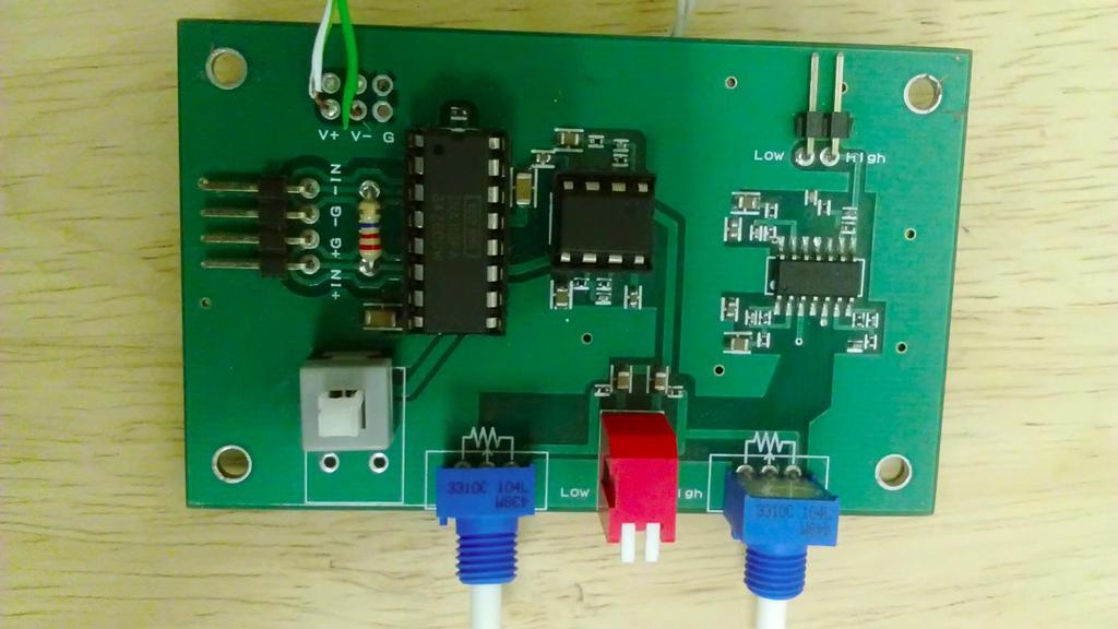
9 PCB


10
11 Procedure for testing Making the circuit on breadboard Powering it up and measuring the offset voltages by grounding the input pins of this IC Sending in sinusoidal signals of different frequencies using Waveform generator and noting the output readings from oscilloscope Plotting frequency versus gain curve Evaluating the transfer function for the schematic and plotting its Bode in MATLAB Comparing experimental plots with theoretical plots Manually done.frequency range used:30-50k Hz( at 55 points)
12 Obtaining theoretical curves:transfer functions
13 TL074 testing :Results
14 TL074 testing :Results
15 TL074 testing :Results No offset voltages, i.e., zero output corresponding to zero input. Theoretical and Experimental plots were similar. The last stage is working properly, something else might have gone wrong. Next step was to test the whole amplifier schematic.
16 Next step: Testing the whole amplifier together Same steps as used for TL074 & Checking step wise gains Frequency range used:1-400 Hz for low pass side(47 points) 320-5k Hz for High pass side(55 points)

17
18 Results Offset voltages : acceptable, of the order of ~0.1 mv (low pass) and ~2mV (high pass). DC volatges of low magnitude don t affect the output.
19 Low frequency side response
20 High frequency peak to peak response


21 Compacted versions of board to be used further
22 Automating the testing procedure Hardware: Matsuzaka Amplifier, Oscilloscope(Tektronix MDO 3014),Waveform Generator(Wavestation 2052),USB cables as USB interfacing is used.other modes of interfacing:ethernet, GPIB Software: Ubuntu LTS Python PyVISA 1.8 py(python backend for VISA) 0.3.dev0 PyUSB Spyder(Python2.7)
23 Learning SCPI Standard Commands for Programmable Instruments (SCPI; often pronounced "skippy") defines a standard for syntax and commands to use in controlling programmable test and measurement devices. set operation (e.g. switching a power supply on) or a query operation (e.g. reading a voltage). Some commands for both setting and querying an instrument.. Concatenating commands Each instrument has its own set of identifiable commands for performing various functions on them, the standard syntax being the same. e.g.,tek.query( *IDN? ),tek.write( ACQ:MOD:AVE ) etc
24 Coding in Python IDE Opening the USB resources and initializing them, doing all the settings required using SCPI commands Changing frequencies in waveform generator and simultaneously changing x and y scales for proper display Changing settings of oscilloscope(acquisition mode,no. of averages,and other settings for proper readings) Saving.isf files as well as amplitude, frequency and peak to peak values obtained in an excel file, for each test frequency. Optimizing time settings and other parameters at each test frequency for accurate measurements. All of the above done automatically by code reducing the testing time from manual 2 hours to automated 15 minutes
25 Automated testing high pass side :Results
26 Automated testing low pass side :Results
27 Next steps: Code optimization, to reduce time and increase accuracy. Noise characteristics of the system:using signal processing techniques like FFT(Fast fourier transform)
28 Noise level and output signals

29

30 Casing with all the connections for electrode inputs and output pins,switches

31 Using it to measure EMG
32 Summary The amplifier was tested successfully,assuring that the schematic can be taken further. The testing procedure was automated, reducing the efforts and time taken, and can be used for testing any amplifier with slight modifications in code. Noise analysis of the amplifier and acquisition system was done. The final prototype to be used was developed and tested successfully on human subject.
33 Future work Final prototype as a model to design new PCBs Teaching Neurophysiology to Undergraduate students and experiments in lab. Making the whole acquisition, digitization and display system, to be used for Clinical applications: Measuring EEG, EMG for measuring brain and muscle function respectively, lowering the cost to 1/10th(20-30k) of currently available systems(2-5 lakhs).
34 Acknowledgements My sincere thanks to my mentor Dr.Manish Arora, for the consistent guidance, support, patience and providing lot of technical knowledge throughout the project. I d like to thank Dr. Mahesh Jayachandra for indirectly guiding me on the application aspects of the bio amplifier and sharing his work experiences in neurophysiology. Also, thanks to Nitin, Research Assistant, under Dr.Mahesh. I d also like to thank Hemang from CPDM lab for helping out when needed. Finally I d like to thank the open source community, helping me at every step in the way.

35
Low_Pass_Filter_1st_Order -- Overview
 Low_Pass_Filter_1st_Order -- Overview 1 st Order Low Pass Filter Objectives: After performing this lab exercise, learner will be able to: Understand and comprehend working of opamp Comprehend basics of
Sallen-Key_High_Pass_Filter -- Overview
 Sallen-Key_High_Pass_Filter -- Overview Sallen-Key High Pass Filter Objectives: After performing this lab exercise, learner will be able to: Understand & analyze working of Sallen-Key topology of active
Inverting_Amplifier -- Overview
 Inverting_Amplifier -- Overview Inverting Amplifier Objectives: After performing this lab exercise, learner will be able to: Understand and comprehend working of opamp Design & build inverting amplifier
Non_Inverting_Voltage_Follower -- Overview
 Non_Inverting_Voltage_Follower -- Overview Non-Inverting, Unity-Gain Amplifier Objectives: After performing this lab exercise, learner will be able to: Understand and comprehend working of opamp Design
ME 365 EXPERIMENT 7 SIGNAL CONDITIONING AND LOADING
 ME 365 EXPERIMENT 7 SIGNAL CONDITIONING AND LOADING Objectives: To familiarize the student with the concepts of signal conditioning. At the end of the lab, the student should be able to: Understand the
Physics 472, Graduate Laboratory DAQ with Matlab. Overview of data acquisition (DAQ) with GPIB
 with GPIB") 1 Overview of data acquisition (DAQ) with GPIB The schematic below gives an idea of how the interfacing happens between Matlab, your computer and your lab devices via the GPIB bus. GPIB stands for General
1 Overview of data acquisition (DAQ) with GPIB The schematic below gives an idea of how the interfacing happens between Matlab, your computer and your lab devices via the GPIB bus. GPIB stands for General
Neurophysiology. The action potential. Why should we care? AP is the elemental until of nervous system communication
 Neurophysiology Why should we care? AP is the elemental until of nervous system communication The action potential Time course, propagation velocity, and patterns all constrain hypotheses on how the brain
BME/ISE 3512 Bioelectronics. Laboratory Five - Operational Amplifiers
 BME/ISE 3512 Bioelectronics Laboratory Five - Operational Amplifiers Learning Objectives: Be familiar with the operation of a basic op-amp circuit. Be familiar with the characteristics of both ideal and
ET 304A Laboratory Tutorial-Circuitmaker For Transient and Frequency Analysis
 ET 304A Laboratory Tutorial-Circuitmaker For Transient and Frequency Analysis All circuit simulation packages that use the Pspice engine allow users to do complex analysis that were once impossible to
Operational Amplifiers 2 Active Filters ReadMeFirst
 Operational Amplifiers 2 Active Filters ReadMeFirst Lab Summary In this lab you will build two active filters on a breadboard, using an op-amp, resistors, and capacitors, and take data for the magnitude
EE 462G Laboratory #1 Measuring Capacitance
 EE 462G Laboratory #1 Measuring Capacitance Drs. A.V. Radun and K.D. Donohue (1/24/07) Department of Electrical and Computer Engineering University of Kentucky Lexington, KY 40506 Updated 8/31/2007 by
10. Computer-Assisted Data Acquisition and Analysis
 10. Computer-Assisted Data Acquisition and Analysis Objective The purpose of this experiment is to practice computer-assisted data acquisition and analysis. Students use LabVIEW programs to control the
Integrators, differentiators, and simple filters
 BEE 233 Laboratory-4 Integrators, differentiators, and simple filters 1. Objectives Analyze and measure characteristics of circuits built with opamps. Design and test circuits with opamps. Plot gain vs.
EE 368 Electronics Lab. Experiment 10 Operational Amplifier Applications (2)
") EE 368 Electronics Lab Experiment 10 Operational Amplifier Applications (2) 1 Experiment 10 Operational Amplifier Applications (2) Objectives To gain experience with Operational Amplifier (Op-Amp). To
EE 368 Electronics Lab Experiment 10 Operational Amplifier Applications (2) 1 Experiment 10 Operational Amplifier Applications (2) Objectives To gain experience with Operational Amplifier (Op-Amp). To
BME 3512 Bioelectronics Laboratory Five - Operational Amplifiers
 BME 351 Bioelectronics Laboratory Five - Operational Amplifiers Learning Objectives: Be familiar with the operation of a basic op-amp circuit. Be familiar with the characteristics of both ideal and real
DEPARTMENT OF ELECTRICAL ENGINEERING LAB WORK EE301 ELECTRONIC CIRCUITS
 DEPARTMENT OF ELECTRICAL ENGINEERING LAB WORK EE301 ELECTRONIC CIRCUITS EXPERIMENT : 3 TITLE : Operational Amplifier (Op-Amp) OUTCOME : Upon completion of this unit, the student should be able to: 1. Gain
Chapter 12: Electronic Circuit Simulation and Layout Software
 Chapter 12: Electronic Circuit Simulation and Layout Software In this chapter, we introduce the use of analog circuit simulation software and circuit layout software. I. Introduction So far we have designed
ECEN 325 Lab 5: Operational Amplifiers Part III
 ECEN Lab : Operational Amplifiers Part III Objectives The purpose of the lab is to study some of the opamp configurations commonly found in practical applications and also investigate the non-idealities
EE 233 Circuit Theory Lab 2: Amplifiers
 EE 233 Circuit Theory Lab 2: Amplifiers Table of Contents 1 Introduction... 1 2 Precautions... 1 3 Prelab Exercises... 2 3.1 LM348N Op-amp Parameters... 2 3.2 Voltage Follower Circuit Analysis... 2 3.2.1
Laboratory 6. Lab 6. Operational Amplifier Circuits. Required Components: op amp 2 1k resistor 4 10k resistors 1 100k resistor 1 0.
 Laboratory 6 Operational Amplifier Circuits Required Components: 1 741 op amp 2 1k resistor 4 10k resistors 1 100k resistor 1 0.1 F capacitor 6.1 Objectives The operational amplifier is one of the most
Biomedical Sensor Systems Laboratory. Institute for Neural Engineering Graz University of Technology
 Biomedical Sensor Systems Laboratory Institute for Neural Engineering Graz University of Technology 2017 Bioinstrumentation Measurement of physiological variables Invasive or non-invasive Minimize disturbance
LAB I. INTRODUCTION TO LAB EQUIPMENT
 LAB I. INTRODUCTION TO LAB EQUIPMENT 1. OBJECTIVE In this lab you will learn how to properly operate the basic bench equipment used for characterizing active devices: 1. Oscilloscope (Keysight DSOX 1102A),
EE 230 Lab Lab 9. Prior to Lab
 MOS transistor characteristics This week we look at some MOS transistor characteristics and circuits. Most of the measurements will be done with our usual lab equipment, but we will also use the parameter
Laboratory 4: Amplification, Impedance, and Frequency Response
 ES 3: Introduction to Electrical Systems Laboratory 4: Amplification, Impedance, and Frequency Response I. GOALS: In this laboratory, you will build an audio amplifier using an LM386 integrated circuit.
10: AMPLIFIERS. Circuit Connections in the Laboratory. Op-Amp. I. Introduction
 10: AMPLIFIERS Circuit Connections in the Laboratory From now on you will construct electrical circuits and test them. The usual way of constructing circuits would be to solder each electrical connection
Biomechanical Instrumentation Considerations in Data Acquisition ÉCOLE DES SCIENCES DE L ACTIVITÉ PHYSIQUE SCHOOL OF HUMAN KINETICS
 Biomechanical Instrumentation Considerations in Data Acquisition Data Acquisition in Biomechanics Why??? Describe and Understand a Phenomena Test a Theory Evaluate a condition/situation Data Acquisition
Operational Amplifier
 Operational Amplifier Joshua Webster Partners: Billy Day & Josh Kendrick PHY 3802L 10/16/2013 Abstract: The purpose of this lab is to provide insight about operational amplifiers and to understand the
P08050 Testing Strategy Document
 P85 Testing Strategy Document IFCN standards 1 for digital recording of clinical EEG Verification 2 3 Square-Wave Calibration Test Summary: Square-wave signals must be recorded at the beginning, using
Experiment 1.A. Working with Lab Equipment. ECEN 2270 Electronics Design Laboratory 1
 .A Working with Lab Equipment Electronics Design Laboratory 1 1.A.0 1.A.1 3 1.A.4 Procedures Turn in your Pre Lab before doing anything else Setup the lab waveform generator to output desired test waveforms,
EE 3305 Lab I Revised July 18, 2003
 Operational Amplifiers Operational amplifiers are high-gain amplifiers with a similar general description typified by the most famous example, the LM741. The LM741 is used for many amplifier varieties
Experiment 5.A. Basic Wireless Control. ECEN 2270 Electronics Design Laboratory 1
 .A Basic Wireless Control ECEN 2270 Electronics Design Laboratory 1 Procedures 5.A.0 5.A.1 5.A.2 5.A.3 5.A.4 5.A.5 5.A.6 Turn in your pre lab before doing anything else. Receiver design band pass filter
EK307 Active Filters and Steady State Frequency Response
 EK307 Active Filters and Steady State Frequency Response Laboratory Goal: To explore the properties of active signal-processing filters Learning Objectives: Active Filters, Op-Amp Filters, Bode plots Suggested
EE 233 Circuit Theory Lab 3: First-Order Filters
 EE 233 Circuit Theory Lab 3: First-Order Filters Table of Contents 1 Introduction... 1 2 Precautions... 1 3 Prelab Exercises... 2 3.1 Inverting Amplifier... 3 3.2 Non-Inverting Amplifier... 4 3.3 Integrating
PHYS 3322 Modern Laboratory Methods I AC R, RC, and RL Circuits
 Purpose PHYS 3322 Modern Laboratory Methods I AC, C, and L Circuits For a given frequency, doubling of the applied voltage to resistors, capacitors, and inductors doubles the current. Hence, each of these
Precalculations Individual Portion Introductory Lab: Basic Operation of Common Laboratory Instruments
 Name: Date of lab: Section number: M E 345. Lab 1 Precalculations Individual Portion Introductory Lab: Basic Operation of Common Laboratory Instruments Precalculations Score (for instructor or TA use only):
EE320L Electronics I. Laboratory. Laboratory Exercise #2. Basic Op-Amp Circuits. Angsuman Roy. Department of Electrical and Computer Engineering
 EE320L Electronics I Laboratory Laboratory Exercise #2 Basic Op-Amp Circuits By Angsuman Roy Department of Electrical and Computer Engineering University of Nevada, Las Vegas Objective: The purpose of
Common-source Amplifiers
 Lab 1: Common-source Amplifiers Introduction The common-source amplifier is one of the basic amplifiers in CMOS analog circuits. Because of its very high input impedance, relatively high gain, low noise,
EE431 Lab 1 Operational Amplifiers
 Feb. 10, 2015 Report all measured data and show all calculations Introduction The purpose of this laboratory exercise is for the student to gain experience with measuring and observing the effects of common
CHARACTERISTICS OF OPERATIONAL AMPLIFIERS - I
 CHARACTERISTICS OF OPERATIONAL AMPLIFIERS - I OBJECTIVE The purpose of the experiment is to examine non-ideal characteristics of an operational amplifier. The characteristics that are investigated include
Department of Electrical & Computer Engineering Technology. EET 3086C Circuit Analysis Laboratory Experiments. Masood Ejaz
 Department of Electrical & Computer Engineering Technology EET 3086C Circuit Analysis Laboratory Experiments Masood Ejaz Experiment # 1 DC Measurements of a Resistive Circuit and Proof of Thevenin Theorem
ECE ECE285. Electric Circuit Analysis I. Spring Nathalia Peixoto. Rev.2.0: Rev Electric Circuits I
 ECE285 Electric Circuit Analysis I Spring 2014 Nathalia Peixoto Rev.2.0: 140124. Rev 2.1. 140813 1 Lab reports Background: these 9 experiments are designed as simple building blocks (like Legos) and students
Operational Amplifiers
 Operational Amplifiers Reading Horowitz & Hill handout Notes, Chapter 9 Introduction and Objective In this lab we will examine op-amps. We will look at a few of their vast number of uses and also investigate
Electrical Engineer. Lab2. Dr. Lars Hansen
 Electrical Engineer Lab2 Dr. Lars Hansen David Sanchez University of Texas at San Antonio May 5 th, 2009 Table of Contents Abstract... 3 1.0 Introduction and Product Description... 3 1.1 Problem Specifications...
BME 3512 Bioelectronics Laboratory Two - Passive Filters
 BME 35 Bioelectronics Laboratory Two - Passive Filters Learning Objectives: Understand the basic principles of passive filters. Laboratory Equipment: Agilent Oscilloscope Model 546A Agilent Function Generator
Lab: Operational Amplifiers
 Page 1 of 6 Laboratory Goals Familiarize students with Integrated Circuit (IC) construction on a breadboard Introduce the LM 741 Op-amp and its applications Design and construct an inverting amplifier
Test No. 2. Advanced Scope Measurements. History. University of Applied Sciences Hamburg. Last chance!! EEL2 No 2
 University of Applied Sciences Hamburg Group No : DEPARTMENT OF INFORMATION ENGINEERING Laboratory for Instrumentation and Measurement L1: in charge of the report Test No. 2 Date: Assistant A2: Professor:
LABORATORY 4. Palomar College ENGR210 Spring 2017 ASSIGNED: 3/21/17
 LABORATORY 4 ASSIGNED: 3/21/17 OBJECTIVE: The purpose of this lab is to evaluate the transient and steady-state circuit response of first order and second order circuits. MINIMUM EQUIPMENT LIST: You will
SAMPLE: EXPERIMENT 2 Series RLC Circuit / Bode Plot
 SAMPLE: EXPERIMENT 2 Series RLC Circuit / Bode Plot ---------------------------------------------------------------------------------------------------- This experiment is an excerpt from: Electric Experiments
Test No. 1. Introduction to Scope Measurements. Report History. University of Applied Sciences Hamburg. Last chance!! EEL2 No 1
 University of Applied Sciences Hamburg Group No : DEPARTMENT OF INFORMATION ENGINEERING Laboratory for Instrumentation and Measurement L: in charge of the report Test No. Date: Assistant A2: Professor:
Experiment A8 Electronics III Procedure
 Experiment A8 Electronics III Procedure Deliverables: checked lab notebook, plots Overview Electronics have come a long way in the last century. Using modern fabrication techniques, engineers can now print
Laboratory Project 1B: Electromyogram Circuit
 2240 Laboratory Project 1B: Electromyogram Circuit N. E. Cotter, D. Christensen, and K. Furse Electrical and Computer Engineering Department University of Utah Salt Lake City, UT 84112 Abstract-You will
DEPARTMENT OF INFORMATION ENGINEERING. Test No. 1. Introduction to Scope Measurements. 1. Correction. Term Correction. Term...
 2. Correction. Correction Report University of Applied Sciences Hamburg Group No : DEPARTMENT OF INFORMATION ENGINEERING Laboratory for Instrumentation and Measurement L: in charge of the report Test No.
A New Low-Cost Bionic Hand
 Paper ID #15623 A New Low-Cost Bionic Hand Mr. TJ Brown, Middle Tennessee State University TJ Brown earned his Bachelor of Science in 2015 at Middle Tennessee State University where he studied Electro-Mechanical
Transmit filter designs for ADSL modems
 EE 233 Laboratory-4 1. Objectives Transmit filter designs for ADSL modems Design a filter from a given topology and specifications. Analyze the characteristics of the designed filter. Use SPICE to verify
Curve Tracer Laboratory Assistant Using the Analog Discovery Module as A Curve Tracer
 Curve Tracer Laboratory Assistant Using the Analog Discovery Module as A Curve Tracer The objective of this lab is to become familiar with methods to measure the dc current-voltage (IV) behavior of diodes
E84 Lab 3: Transistor
 E84 Lab 3: Transistor Cherie Ho and Siyi Hu April 18, 2016 Transistor Testing 1. Take screenshots of both the input and output characteristic plots observed on the semiconductor curve tracer with the following
ECE Electronics Circuits and Electronics Devices Laboratory. Gregg Chapman
 ECE 2300 Electronics Circuits and Electronics Devices Laboratory Gregg Chapman Laboratory 6 Diodes Background Diodes Small Signal Rectifiers Half wave Full Wave Zener Diodes Light Emitting Diodes (LED)
from signals to sources asa-lab turnkey solution for ERP research
 from signals to sources asa-lab turnkey solution for ERP research asa-lab : turnkey solution for ERP research Psychological research on the basis of event-related potentials is a key source of information
OPERATIONAL AMPLIFIERS LAB
 1 of 6 BEFORE YOU BEGIN PREREQUISITE LABS OPERATIONAL AMPLIFIERS LAB Introduction to Matlab Introduction to Arbitrary/Function Generator Resistive Circuits EXPECTED KNOWLEDGE Students should be familiar
Four-Channel Differential AC Amplifier
 Four-Channel Differential AC Amplifier INSTRUCTION MANUAL FOR HIGH-GAIN DIFFERENTIAL AMPLIFIER MODEL 1700 Serial # Date A-M Systems, Inc. PO Box 850 Carlsborg, WA 98324 U.S.A. 360-683-8300 800-426-1306
Laboratory Exercises for Analog Circuits and Electronics as Hardware Homework with Student Laptop Computer Instrumentation
 Laboratory Exercises for Analog Circuits and Electronics as Hardware Homework with Student Laptop Computer Instrumentation Marion O. Hagler Department of Electrical and Computer Engineering Mississippi
LABORATORY 3 v3 CIRCUIT ELEMENTS
 University of California Berkeley Department of Electrical Engineering and Computer Sciences EECS 100, Professor Leon Chua LABORATORY 3 v3 CIRCUIT ELEMENTS The purpose of this laboratory is to familiarize
EE2210 Laboratory Project 1 Fall 2013 Function Generator and Oscilloscope
 EE2210 Laboratory Project 1 Fall 2013 Function Generator and Oscilloscope For students to become more familiar with oscilloscopes and function generators. Pre laboratory Work Read the TDS 210 Oscilloscope
CHARACTERIZATION OF OP-AMP
 EXPERIMENT 4 CHARACTERIZATION OF OP-AMP OBJECTIVES 1. To sketch and briefly explain an operational amplifier circuit symbol and identify all terminals. 2. To list the amplifier stages in a typical op-amp
Intro To Engineering II for ECE: Lab 7 The Op Amp Erin Webster and Dr. Jay Weitzen, c 2014 All rights reserved.
 Lab 7: The Op Amp Laboratory Objectives: 1) To introduce the operational amplifier or Op Amp 2) To learn the non-inverting mode 3) To learn the inverting mode 4) To learn the differential mode Before You
ECEN Network Analysis Section 3. Laboratory Manual
 ECEN 3714----Network Analysis Section 3 Laboratory Manual LAB 07: Active Low Pass Filter Oklahoma State University School of Electrical and Computer Engineering. Section 3 Laboratory manual - 1 - Spring
PHYSICS 330 LAB Operational Amplifier Frequency Response
 PHYSICS 330 LAB Operational Amplifier Frequency Response Objectives: To measure and plot the frequency response of an operational amplifier circuit. History: Operational amplifiers are among the most widely
Pre-Lab. Introduction
 Pre-Lab Read through this entire lab. Perform all of your calculations (calculated values) prior to making the required circuit measurements. You may need to measure circuit component values to obtain
ECE Lab #4 OpAmp Circuits with Negative Feedback and Positive Feedback
 ECE 214 Lab #4 OpAmp Circuits with Negative Feedback and Positive Feedback 20 February 2018 Introduction: The TL082 Operational Amplifier (OpAmp) and the Texas Instruments Analog System Lab Kit Pro evaluation
6.101 Introductory Analog Electronics Laboratory
 6.101 Introductory Analog Electronics Laboratory Spring 2015, Instructor Gim Hom Project Proposal Transmitting, Receiving, and Interpreting ECG Waveforms Daniel Moon (dhmoon@mit.edu) Thipok (Ben) Rak-amnouykit
Introduction to basic laboratory instruments
 BEE 233 Laboratory-1 Introduction to basic laboratory instruments 1. Objectives To learn safety procedures in the laboratory. To learn how to use basic laboratory instruments: power supply, function generator,
University of Jordan School of Engineering Electrical Engineering Department. EE 219 Electrical Circuits Lab
 University of Jordan School of Engineering Electrical Engineering Department EE 219 Electrical Circuits Lab EXPERIMENT 7 RESONANCE Prepared by: Dr. Mohammed Hawa EXPERIMENT 7 RESONANCE OBJECTIVE This experiment
ELR 4202C Project: Finger Pulse Display Module
 EEE 4202 Project: Finger Pulse Display Module Page 1 ELR 4202C Project: Finger Pulse Display Module Overview: The project will use an LED light source and a phototransistor light receiver to create an
ECE 4670 Spring 2014 Lab 1 Linear System Characteristics
 ECE 4670 Spring 2014 Lab 1 Linear System Characteristics 1 Linear System Characteristics The first part of this experiment will serve as an introduction to the use of the spectrum analyzer in making absolute
Chapter 3 THE DIFFERENTIATOR AND INTEGRATOR Name: Date
 AN INTRODUCTION TO THE EXPERIMENTS The following two experiments are designed to demonstrate the design and operation of the op-amp differentiator and integrator at various frequencies. These two experiments
BIOE 123 Module 3. Electronics 2: Time Varying Circuits. Lecture (30 min) Date. Learning Goals
 Date. Learning Goals") BIOE 123 Module 3 Electronics 2: Time Varying Circuits Lecture (30 min) Date Learning Goals Learn about the behavior of capacitors and inductors Learn how to analyze time-varying circuits to quantify parameters
BIOE 123 Module 3 Electronics 2: Time Varying Circuits Lecture (30 min) Date Learning Goals Learn about the behavior of capacitors and inductors Learn how to analyze time-varying circuits to quantify parameters
DEPARTMENT OF ELECTRICAL ENGINEERING AND COMPUTER SCIENCE MASSACHUSETTS INSTITUTE OF TECHNOLOGY CAMBRIDGE, MASSACHUSETTS 02139
 DEPARTMENT OF ELECTRICAL ENGINEERING AND COMPUTER SCIENCE MASSACHUSETTS INSTITUTE OF TECHNOLOGY CAMBRIDGE, MASSACHUSETTS 019.101 Introductory Analog Electronics Laboratory Laboratory No. READING ASSIGNMENT
Physics 310 Lab 6 Op Amps
 Physics 310 Lab 6 Op Amps Equipment: Op-Amp, IC test clip, IC extractor, breadboard, silver mini-power supply, two function generators, oscilloscope, two 5.1 k s, 2.7 k, three 10 k s, 1 k, 100 k, LED,
Experiment A8 Electronics III Procedure
 Experiment A8 Electronics III Procedure Deliverables: checked lab notebook, plots Overview Electronics have come a long way in the last century. Using modern fabrication techniques, engineers can now print
Operational Amplifiers
 Objective Operational Amplifiers Understand the basics and general concepts of operational amplifier (op amp) function. Build and observe output of a comparator and an amplifier (inverting amplifier).
Electronics I. laboratory measurement guide
 Electronics I. laboratory measurement guide Andras Meszaros, Mark Horvath 2015.02.01. 5. Measurement Basic circuits with operational amplifiers 2015.02.01. In this measurement you will need both controllable
LAB II. INTRODUCTION TO LAB EQUIPMENT
 1. OBJECTIVE LAB II. INTRODUCTION TO LAB EQUIPMENT In this lab you will learn how to properly operate the oscilloscope Keysight DSOX1102A, the Keithley Source Measure Unit (SMU) 2430, the function generator
ECE159H1S University of Toronto 2014 EXPERIMENT #2 OP AMP CIRCUITS AND WAVEFORMS ECE159H1S
 ECE159H1S University of Toronto 2014 EXPERIMENT #2 OP AMP CIRCUITS AND WAVEFORMS ECE159H1S OBJECTIVES: To study the performance and limitations of basic op-amp circuits: the inverting and noninverting
UNIVERSITY OF CALIFORNIA College of Engineering Department of Electrical Engineering and Computer Sciences
 UNIVERSITY OF CALIFORNIA College of Engineering Department of Electrical Engineering and Computer Sciences EECS 145L: Electronic Transducer Laboratory FINAL EXAMINATION Fall 2013 You have three hours to
GENERATION OF SIGNALS USING LABVIEW FOR MAGNETIC COILS WITH POWER AMPLIFIERS
 GENERATION OF SIGNALS USING LABVIEW FOR MAGNETIC COILS WITH POWER AMPLIFIERS Ashmi G V 1, Meena M S 2 1 ER&DCI-IT, Centre for Development of Advanced Computing, Thiruvananthapuram(India) 2 LAMP Group,
EECE Circuits and Signals: Biomedical Applications. Lab ECG I The Instrumentation Amplifier
 EECE 150 - Circuits and Signals: Biomedical Applications Lab ECG I The Instrumentation Amplifier Introduction: As discussed in class, instrumentation amplifiers are often used to reject common-mode signals
Laboratory 4 Operational Amplifier Department of Mechanical and Aerospace Engineering University of California, San Diego MAE170
 Laboratory 4 Operational Amplifier Department of Mechanical and Aerospace Engineering University of California, San Diego MAE170 Megan Ong Diana Wu Wong B01 Tuesday 11am April 28 st, 2015 Abstract: The
ENG 100 Lab #2 Passive First-Order Filter Circuits
 ENG 100 Lab #2 Passive First-Order Filter Circuits In Lab #2, you will construct simple 1 st -order RL and RC filter circuits and investigate their frequency responses (amplitude and phase responses).
RLC Frequency Response
 1. Introduction RLC Frequency Response The student will analyze the frequency response of an RLC circuit excited by a sinusoid. Amplitude and phase shift of circuit components will be analyzed at different
EE 210 Lab Exercise #5: OP-AMPS I
 EE 210 Lab Exercise #5: OP-AMPS I ITEMS REQUIRED EE210 crate, DMM, EE210 parts kit, T-connector, 50Ω terminator, Breadboard Lab report due at the ASSIGNMENT beginning of the next lab period Data and results
Laboratory Experiment #1 Introduction to Spectral Analysis
 J.B.Francis College of Engineering Mechanical Engineering Department 22-403 Laboratory Experiment #1 Introduction to Spectral Analysis Introduction The quantification of electrical energy can be accomplished
Lab 6: Instrumentation Amplifier
 Lab 6: Instrumentation Amplifier INTRODUCTION: A fundamental building block for electrical measurements of biological signals is an instrumentation amplifier. In this lab, you will explore the operation
A Custom Vibration Test Fixture Using a Subwoofer
 Paper 068, ENT 205 A Custom Vibration Test Fixture Using a Subwoofer Dale H. Litwhiler Penn State University dale.litwhiler@psu.edu Abstract There are many engineering applications for a source of controlled
Class #16: Experiment Matlab and Data Analysis
 Class #16: Experiment Matlab and Data Analysis Purpose: The objective of this experiment is to add to our Matlab skill set so that data can be easily plotted and analyzed with simple tools. Background:
Prototype Testing Lab Results for INA116 Instrumentation Amplifier
 1 Prototype Testing Lab Results for INA116 Instrumentation Amplifier This document provides an overview of our lab test results with INA116 Instrumentation Amplifier. Our goal is to obtain accurate ph
Lab 0: Introduction to TIMS AND MATLAB
 TELE3013 TELECOMMUNICATION SYSTEMS 1 Lab 0: Introduction to TIMS AND MATLAB 1. INTRODUCTION The TIMS (Telecommunication Instructional Modelling System) system was first developed by Tim Hooper, then a
Lab: Using filters to build an electrocardiograph (ECG or EKG)
") Page 1 /6 Lab: Using filters to build an electrocardiograph (ECG or EKG) Goal: Use filters and amplifiers to build a circuit that will sense and measure a heartbeat. You and your heartbeat Did you know
Page 1 /6 Lab: Using filters to build an electrocardiograph (ECG or EKG) Goal: Use filters and amplifiers to build a circuit that will sense and measure a heartbeat. You and your heartbeat Did you know
Lab 2: Discrete BJT Op-Amps (Part I)
") Lab 2: Discrete BJT Op-Amps (Part I) This is a three-week laboratory. You are required to write only one lab report for all parts of this experiment. 1.0. INTRODUCTION In this lab, we will introduce and
Lab 2: Discrete BJT Op-Amps (Part I) This is a three-week laboratory. You are required to write only one lab report for all parts of this experiment. 1.0. INTRODUCTION In this lab, we will introduce and
Lab #5 Steady State Power Analysis
 Lab #5 Steady State Power Analysis Steady state power analysis refers to the power analysis of circuits that have one or more sinusoid stimuli. This lab covers the concepts of RMS voltage, maximum power
EMG Electrodes. Fig. 1. System for measuring an electromyogram.
 1270 LABORATORY PROJECT NO. 1 DESIGN OF A MYOGRAM CIRCUIT 1. INTRODUCTION 1.1. Electromyograms The gross muscle groups (e.g., biceps) in the human body are actually composed of a large number of parallel