CompuLign User Guide - V2.0
|
|
|
- Benedict Barber
- 5 years ago
- Views:
Transcription
1 CompuLign User Guide - V2.0 I. Overview The CompuLign computer driven alignment tool as developed by L. J. Haskell was designed and built as a multi-functional test device to help radio hobbyists align antique and vintage radios and vintage audio equipment. The design is based on one Arduino Nano micro controller as the main processor plus 2 frequency generation modules based on the AD9850 frequency generator chip. There are 4 outputs and 1 input accessed via BNC type connectors. The functions of the device are: 1. A sine wave generator of 1 volt P-P with output frequency from 1 Hz to 40 MHz set in steps of 1 Hz. 2. A square wave generator of 5 volts P-P with the same frequency range 3. An RF generator of 1 volt P-P with a frequency range of 20 KHz to 40 MHz AM modulated from 0-100% by the sine wave generator output. 4. An RF sweep generator with above output and frequency range that can be swept at multiple rates up to about 50 Hz. 5. A sweep voltage output generating a ramp voltage that can be used to drive an oscilloscope X-axis for a sweep alignment display 6. An input via BNC connector to measure the radio response during sweeps which allows for an internal display of the response displayed on the LCD screen thus eliminating the need for an oscilloscope. II. Functional Block Diagram The design of the device consists of multiple functional components. These are shown in Figure 1. Figure 1 - Circuit diagram schematic of DDS module
2 At the center is the Arduino Nano micro controller which contains all of the controlling software and has interfaces to all of the programmable components. The Nano drives 2 DDS function generator modules, one used to generate sine and square waves of a wide range of frequencies and one to generate a sweepable RF output. The first generator is also used as an input to the MOD, i.e. modulation component to control the AM modulation of the RF output generator. The SYNC DAC (digital to analog converter) is used to generate a saw tooth ramp voltage signal to drive the horizontal sweep of an oscilloscope display when doing a sweep operation. An input amplifier is provided for accepting the input signal from the radio under test for operations where the internal display is used. A reference voltage generator is used for shifting the input voltage to a range of voltages that can be measured by the Arduino Nano s internal analog to digital converter. The LCD display provides the user interface for all of the mode and frequency settings as well as a display of the output during internal display operations. Finally, the Rotary Switch is used to select and change all of the required settings. Thus the total functionality of the device allows the radio technician to do a full alignment of an AM or FM radio in conjunction either with an oscilloscope or as a stand alone device. As a stand alone, the device performs the functions of 3 devices - RF sweep generator, frequency counter, and oscilloscope - and can function as the single device needed for an alignment. III. Circuit Design Refer to the schematic diagram in Figure A in the Appendix. Component U1 is the Arduino Nano micro controller that is programmed to provide all of the control and generates the settings for the other main components. DDS1 is the module that generates the sine and square waves and is based on the Analog Devices AD9850 chip. Likewise, DDS2 is a modified DDS generator that provides the RF output that is also amplitude modulated and can be set to generate a sweep of frequencies for the alignment operation. Component DAC1 is a digital to analog converts chip that is used to generate the ramp voltage signal for the oscilloscope X-axis display sweep while the signal is input on the Y-axis of the scope. These chips are then surrounded by support circuitry. At the top left is the 7805 regulator chip that supplies the 5volts for the rest of the board. Diodes D3 and D4 are used to drop the input from 9 volts to 7.5 volts so that the 7805 will need to drop less voltage and thus operate cooler. If a 7.5 volt wall plug is used, these diodes must be removed and replaced with jumper wires. Component U5 is a 3 volt regulator to provide power to the LCD display. The IC marked U3 is a level shifter to buffer 5 volt signals to the required 3 volts signals to the LCD display. The circuitry surrounding FET transistor Q1 takes the signal output from the DDS1 generator module and uses that as an input to Q1 to provide a variable resistance and thus a variable current to the DDS2 output gain stage. In this manner, the output of DDS1 will cause AM modulation of the output of DDS2. Transistor Q2 provides a buffered low impedance output of the RF signal from DDS2. The op amp U2.2 is used to buffer the input signal from the radio into the analog input of the Arduino Nano. Resistor R12 and R13 provide high input impedance while diodes D1 and D2 provide over and under voltage protection. The combination of R18 and C12 connected to Nano pin 10, provide a DC reference signal for level shifting of the input so that a negative signal found in AGC circuits can be translated or shifted to a positive signal for the Nano pin A0 analog to digital converter.

3 IV. Hardware Construction The hardware design consists of a single printed circuit board containing all of the components. By placing all components on the board, the case construction is simplified to simply bolting the board to the case enclosure. No additional wiring is required. Power is supplied by a 9 volt wall module supply into a standard power jack. A parts list is supplied in the appendix along with the download URL of the Gerber file for constructing the circuit board. Thus construction simply consists of populating the circuit board and inserting it into the enclosure. This guide assumes the user has knowledge of tools and techniques for building the circuit board. An enclosure has been designed by the author using clear acrylic material cut using a laser machine. Before the DDS9850 module used for the RF generator is inserted onto the circuit board, it must be modified. Note that ONLY the DDS2 module is modified. The circuit diagram of the module is shown below in Figure 2 for reference on the parts on the DDS module. A link to the application note which explains how to do the AM modulation is provided as a reference in the Appendix as AN-423. Figure 2 - Circuit diagram schematic of DDS module


4 Figure 3 - Bottom view of DDS module Figure 4 - Top view of DDS module
5 The first job is to bring the RSET pin (12) out to the connector. To free up the pin you have to cut the trace pin labeled as DATA, which is the same as pin D7 so that pin is now used as the serial data pin. Cut the trace where the red arrow points. See Figure 3. Then remove the 3.9K resistor, R6. Finally solder a wire from 3.9k resistor R6 pad closest to the AD9850 chip to the freed up DATA pin. See the photo in Figure 4. The second mod brings the current output pins directly, without load resistors connected to them, out of the board so that they can be hooked to the transformer as shown in schematic. The output filter on IOUT output (pin 21) also needs to be eliminated. Simply remove all filter components and load resistors from the board - R4, R9, C1, L1, C2, C3, L2, C4, C5, L3, C6, C7, R5. I used a fine needle nosed pliers to crush and remove the components rather than risk desoldering and damaging other components or causing solder bridges all over the place. Then to connect the IOUT to ZOUT2 pin of the module you simply solder a wire from a pad closer to board edge of R4 resistor to pad of R5 resistor, also closer to the board edge. Don't worry if you accidentally bridge the solder to the pad of C7 since R5 and C7 are connected on the board. This completes the modification of DDS2. As the components are placed onto the main printed circuit board, note the orientation of each part. As you likely know, parts like resistors have no polarity and can be inserted in either of 2 orientations. The top of the circuit board is stenciled with guides to show which part goes where and how it must be inserted. Refer to figure A2 in the Appendix. Note the red arrows that mark keys on the components that are guides for proper placement, e.g. a dot on pin 1 for ICs and a plus sign for the positive lead of an electrolytic capacitor. The LCD is mounted offset from the surface of the board using 1/2 spacers. This places it closer to the top cover of the enclosure for easier viewing. The header that is used is 8 pins whereas the LCD has 9 pins. That 9th pin is placed outside of the connector and hence makes no contact since it is not needed (MISO signal). There is a hole on the circuit board for it if the LCD is mounted directly on the board as you wish. V. Software installation All software is contained in the single Arduino Nano micro controller. The device is normally sold with an onboard boot loader installed. The Arduino Development Environment is freely downloadable from the website arduino.cc. This tool provides a code editor, management of libraries, and an uploader to place compiled code onto the Arduino Nano module. Software is supplied as both source code and a pre-built image by the author and hosted on the author s website. The web address is shown in the Appendix.The software can be downloaded onto your local PC or Mac and compiled then downloaded onto the Nano using a micro USB cable connected to the USB port on the Arduino Nano module. It is expected that software updates will be issued from time to time as users get experience and bugs are fixed or new features added. Each release has a README file which explains the changes in the software as well as instructions to compile and upload the code to the Arduino. It is possible as previously mentioned to upload the code from a pre-compile file supplied in the release software without the need for a full development environment. This is done using a program called XLoader. This can be obtained at the website listed in the Appendix. It is
6 recommended however, that the user become familiar with the development environment so that local modifications and a deeper understanding of the code can be learned. After the software is installed, the DDS module boards must be adjusted for waveform duty cycle. Each board has a small square blue pot for this. For each of the FN and RF generators, set a frequency value, and feed the output to an oscilloscope. Adjust the blue pot for a 50% duty cycle. VI. Case Assembly The case is made from 1/8 clear acrylic plastic panels that were laser cut into 6 pieces with edge teeth to form a pressure fit case. There are 4 bolts that hold the circuit board and the top and bottom panels together. The other 4 panels, left, right, top, and bottom are fitted into place with the edge teeth and then clamped down to hold in place by the 4 bolts. The case can be assembled in 2 ways. The easy way is to have the bolt heads on the bottom panel and the nuts showing on the front panel. This is done by placing the screws through the bottom panel, then placing the spacers, circuit board, nut, then top panel in place. The 4 other panels are then placed as the assembly proceeds. For a more aesthetic look with the bolt heads on top, the assembly is a little trickier but worthwhile for appearance. Follow these steps (refer to assembly photos in figure A4): 1. First thread the 4 bolts into the front panel and secure with nuts gently up against the front panel holding the bolts in place. See upper left photo in figure A4. 2. Next thread the circuit board onto the bolts, then spacers, and finally the back panel. Note carefully that the back panel has the holes closer to the bottom edge than at the top edge.thread the nuts onto the bolts, holding the front, circuit board, and back panel in place. The nuts should be threaded so that the bolt shaft barely comes through the nut. 3. Place the left side panel between the front and back panels. This will require some jiggling of the panel to get the power connector to seat into the cut out hole. You will likely need to loosen the nuts on the bolts to give enough room for the left panel to snap into place. 4. Next place the right panel with the BNC connector holes on the assembly. Note that the BNC hole at the bottom is closest to it s edge. Again loosen the nuts at the back of the back panel slightly to allow the panel to snap into place. 5. Next, move the nuts on the back of the front panel down to the circuit board to tighten the circuit board up against the spacers holding the board tight to the back panel. The assembly now should look like the tall photo at the right of figure A4. 6. Finally, place the top and bottom panels onto the assembly, loosening the nuts as needed to allow room for the panels to snap into place. When every panel is in place, tighten all the nuts on the back using a screwdriver in the top bolt slot and a socket on the back nut. Tighten well but no too much as to harm the plastic. 7. Note that, as software updates need to be applied in the future, the bottom 2 bolts can be loosened and the bottom panel removed, exposing the usb connector on the Arduino Nano for use in downloading new software. The final assembly is now as shown in figure A5.
7 VII.Operation Modes A. User Interface Overview The user interface consists of the LCD screen and is controlled by the rotary selector. There are 3 sections of the display - mode settings on the upper left, frequency settings on the upper right, and internal graph display at the lower half of the screen. In the right column are the settings for the FN, i.e. the function generator which sets the frequency for the sine, square, and the modulation frequency. Next is the RF generator setting, and finally, the BW or bandwidth setting for sweeping the frequency. Figure 5 - Basic screen overview On the left column are the settings for mode (functional mode) which can be set to one of 3 modes: FIX, which is a fixed frequency output for the RF generator (the Function generator is always fixed and not swept) SWe, which is the external sweep mode where the RF generator is swept across a range of frequencies, and a sync signal is generated for the X-axis of an oscilloscope SWi, where the RF generator is swept and the display for the response is set on the LCD screen itself with internal software providing a sweep for the display. Next in the left column are the Rate setting which sets the sweep rate, then the Mark setting for the sweep markers on the internal display or the center mark intensity on the external display.
8 Finally the Bias setting for the level shift on the input voltage. These setting will be discussed in the sections below. The graph display at the lower half of the screen is only used during internal sweep operation. This will display the response seen at the input connector. When moving to either the FIX or SWe settings, this area will be blanked. To change any of the settings, the rotary selector is used. This is the control directly below the screen. As the selector is rotated, a selected digit is shown in the color white rather then the default color for that field. For example, in the display shown, the value of the Rate field is highlighted. The selector will thus highlight, as it is rotated, each digit of every field, including both the frequency fields and the function/mode fields. After a digit is selected, the rotary is pushed down to set it s switch to modify. While the switch is held pushed down, rotating the selector will change the value of that digit. In this way, each digit of every field can be modified to the value required for the needed operation. The action may be a little awkward at first, but practice will make the operation go smoothly. B. Fixed Mode for Function and RF Generator Operation The FIX mode of operation is used to generate fixed frequencies on both the function generator and the RF generator. Note, of course, the the function generator always generates a fixed frequency. With the mode set to FIX, the frequency is set for the FN setting for the function generator and by modifying the RF setting, the frequency of the RF generator is changed. While in this mode the BW, Rate, Mark, and Bias settings have no affect of the operation. However, Amplitude Modulation of the RF generator by the frequency of the FN generator is active. To control the level of modulation, the R1 Pot (furthest left) is rotated to the desired level. To change the level of the FN generator sine wave, the R11 pot (lower center on the board) is used. The square wave output is not able to be adjusted but is fixed at 5 volts peak-to-peak. Finally, the level of the RF generator is set using the R6 pot, the furthest right control. C. External Sweep Operation In the external sweep mode, the device will output an RF signal at the set center frequency across a range of frequencies according to the bandwidth setting. In addition, the modulation is active and is set by the FN generator for the frequency and R1 for the modulation level. For example, is the display overview in Figure 5, we have an RF frequency of 455KHz and a bandwidth of 40KHz. So the sweep will run from 435KHz to 475 KHz. As the frequency is sweep, the voltage output on the Sync output, BNC 4, is ramped from approximately 0 to 5 volts. This is connected to the X-axis of the oscilloscope to show a proper X-Y graph of response. See the section on alignment examples. There is a single marker at the center frequency which is set by a small delay on the ramp sync signal. This shows up as a bright spot on the scope allowing for precise settings. The Marker control (Mark) will make the marker brighter with a higher set number. The Rate setting is used to decrease or increase the rate of sweep. Currently, the rate is a relative number from 0 to 9 used to specify the rate of the sweep from about 0.5Hz to about 50Hz.
9 D. Internal Sweep Operation The internal sweep operation removes the need for an external oscilloscope. The LCD display is used to show the radio s response to the generated RF signal. The function generator and RF generator as well as the bandwidth are all set as above for the external sweep. The rate is also chosen to specify the sweep rate. However, for the internal sweep, the sync output is disabled since it is not used. In addition, two other settings are needed. First the marker setting is used to set the width of the markers on the display to show the output bandwidth of a radio response. Currently, the marker value is a number from 0 to 9. Each number adds 10% of the bandwidth to the marker position. So, if the bandwidth is set to 20KHz and the RF frequency set to 455KHz, a marker position of 5 would shows markers at 445KHZ and 465KHz. The bias setting is used to specify a vertical offset to the display. The bias varies the level shifting of the input voltage by 0 to 4.9 volts in 0.1 volt steps. Thus a setting of 2.5 would cause an input voltages of +/- 2.5 volts to be seen as an input of approximately 0 to 5 volts. The best value of this setting is discussed in the operational examples section.

10 VIII.Operational Examples 1. AM IF Alignment - External Display Certainly, the RF generator can be used as a fixed modulated source for the classic IF alignment using a voltmeter to measure the peak of the response signal from the radio s IF stage. To do this, simply set the mode as FIX and set the RF frequency to the proper value, typically 455KHz, the FN generator to a modulation frequency such as 400. Then adjust the modulation level to about 30% and use this as the signal source as specified in the radio s alignment instructions. But we want to discuss the sweep alignment process here to show the sweep functionality of the device. For an AM sweep with an external display, the RF frequency should be set to the radio s IF frequency, e.g. 455KHz, according to the circuit schematic. The FN frequency is set to 400Hz typically, and modulation level to about 30%. The mode is set to SWe and the Rate to 0 initially. The BW is set to a wide range initially such as 40KHz. The SYNC output is connected to the X input of an oscilloscope (typically channel 1) and the Y axis is connected to the output of the detector, usually the top of the volume control. Set the scope sweep to the X/Y setting. One of the probes is connected to circuit ground on the radio. Of course, be sure to run an AC/DC radio through an isolation transformer for power to prevent damage to the scope. Follow the directions for radio alignment on the best way to align each stage. I prefer to tune each IF stage separately so that interaction of the stages in minimized. By first aligning the detector, then the 2nd IF, then the first IF, interaction is minimized. The scope will display a signal that you will attempt to peak at the point of the bright marker which is the center frequency of the sweep. See figure 6. Change the rate to slow down the sweep for best viewing and change to BW setting to fine tune the peaking frequency Figure 6 - AM IF Peaking on External Scope Display
11 2. AM IF Alignment - Internal Display The AM IF alignment using the internal display is similar to the external mode. Set the frequency of the FN, RF, BW, and rate as stated under the external method. Set the mode to SWi. Set the Mark to a position like 5 to show the bandwidth of the response. Set the bias level to 4.9. This will level shift a negative detector voltage (think AGC) to a positive voltage so the Arduino ADC can measure it. Connect the input to the detector output, typically the top of the volume control. Adjust the Rate to get a good display. Some radios do not handle a fast sweep. For the internal display, a slow sweep works well since we do not have to worry about fiddling with a scope X/Y display. See figure 7 for a typical display that is peaked. Figure 7 - Internal AM IF Peaking Display

12 3. FM IF Alignment Typically, the alignment of the IF transformers on an FM radio calls for unmodulated frequency inserted at the front end of the radio and peaked using the level of the output signal on the display of the oscilloscope. The classic IF frequency for the FM radio is 10.7 MHz. As with AM IF alignment, it is best to start from the last stages, working forward, aligning each IF transformer by injecting the RF signal at the grid of the tube driving that IF stage. Thus for this operation, the mode is set to SWe, the RF generator frequency is set to 10.7MHz, and BW is set to something reasonable like 500KHz. As before the SYNC output is connected to the X-axis input of the oscilloscope and the output of the IF stage is connected to the Y-axis channel. Again, this is very similar to the AM IF sweep alignment. A classic output is shown in Figure 8. Figure 8 - FM IF Peaking Display


13 4. FM IF Alignment - Internal Display If the internal display measurement is done the same as the external measurement, the limited bandwidth of the device will prevent an acceptable display. However, by measuring the voltage level at the grid of the limiter section, a display will show proper peaked response at the center frequency for the IF stages. The best probe point is shown in Figure 9 at the red arrow. Figure 9 - Grid Resistor Probe Point for IF Internal Sweep Measurement Using the typical sweep settings as shown in figure 10 will allow for peaking of the IF stages. There may or may not be enough output voltage from the RF generator to peak each stage individually. Figure 10 - FM IF Internal Measurement

14 5. FM Detector Alignment - External Display The alignment of the FM detector typically generates what is known as the classic S-curve showing the response of the detector across the bandwidth needed centered at the IF frequency. The goal is to get a clean linear slope as the frequency is swept across the bandwidth of the IF circuit. To perform this operation, we follow the detailed instructions given for the radio under test. This typically calls for an unmodulated signal swept across a bandwidth of 500KHz centered on the IF frequency. The input to the Y-axis is taken at the center point of the discriminator. The Rate can be adjusted for the best display. The SYNC is connected as before to the X-axis channel. A typical output is shown in Figure 11. Figure 11 - FM Detector S-Curve Display

15 6. FM Detector Alignment - Internal Display The alignment of the FM detector using the internal display is similar to the external operation. The RF frequency is set to the IF value, typically 10.7MHz. Bandwidth is set to 500KHz to start and can be adjusted for the best display. For the internal, the Mark can now be used to set up the markers. The Bias is set to 5 giving a 2.5 volt offset. This is used because the typical voltage off of the detector is targeted for +/- 2.5 volts depending on the RF output voltage level. Thus with a Bias of 2.5 (2.5 volts), the input voltage of +/- 2.5 is shifted to 0 to 5 volts and can then be properly converted for display. The device input is connected to the discriminator circuit as directed by the alignment instructions. See Figure 12 for a typical display. Figure 12 - FM Detector S-Curve Display on Internal LCD
16 IX.Appendix Figure A1 - Circuit Design Schematic

17 Figure A2 - Top view of Circuit Board Red Arrows show positioning markers for certain components, e.g. pin 1 of the IC

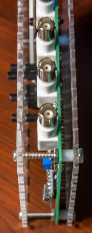
18 Figure A3 - Side view showing LCD header and exposed pin 9


19 Figure A4 - Assembly Steps

20 Figure A5 - Final Assembly
21 Here are links to important documents as mentioned in the text above: 1. Analog Devices AN-423 PDF on how to accomplish Amplitude Modulation with the AD XLoader website for download 3. Software can be downloaded at Release-latest.zip 4. The Gerber files to construct the circuit board are at generator-gerber.zip
Sweep / Function Generator User Guide
 I. Overview Sweep / Function Generator User Guide The Sweep/Function Generator as developed by L. J. Haskell was designed and built as a multi-functional test device to help radio hobbyists align antique
Assembly Manual for VFO Board 2 August 2018
 Assembly Manual for VFO Board 2 August 2018 Parts list (Preliminary) Arduino 1 Arduino Pre-programmed 1 Faceplate Assorted Header Pins Full Board Rev A 10 104 capacitors 1 Rotary encode with switch 1 5-volt
Oscilloscope Current Probe Adapter Plus
 Oscilloscope Current Probe Adapter Plus Paul "LeoNerd" Evans Assembly To avoid damage during shipping, this unit is supplied with the four 4mm gold binding posts unattached from
Combinational logic: Breadboard adders
 ! ENEE 245: Digital Circuits & Systems Lab Lab 1 Combinational logic: Breadboard adders ENEE 245: Digital Circuits and Systems Laboratory Lab 1 Objectives The objectives of this laboratory are the following:
Starving Student II. Starving Student II. SS2 guide. Written By: 6L guides.diyaudio.com/ Page 1 of 24
 SS2 guide Written By: 6L6 2019 guides.diyaudio.com/ Page 1 of 24 INTRODUCTION This is a build guide for the hybrid headphone/pre-amplifier. You can buy a kit at the SSII product listing on the diyaudio
IR add-on module circuit board assembly - Jeffrey La Favre January 27, 2015
 IR add-on module circuit board assembly - Jeffrey La Favre January 27, 2015 1 2 For the main circuits of the line following robot you soldered electronic components on a printed circuit board (PCB). The
Assembly Instructions
 Assembly Instructions For the SSQ-2F 3.1 MHz Rife Controller Board Kit v1.41 Manual v1.00 2012 by Ralph Hartwell Spectrotek Services GENERAL ASSEMBLY INSTRUCTIONS Arrange for a clean work surface with
Laboratory 3 (drawn from lab text by Alciatore)
") Laboratory 3 (drawn from lab text by Alciatore) The Oscilloscope Required Components: 1 10 resistor 2 100 resistors 2 lk resistors 1 2k resistor 2 4.7M resistors 1 0.F capacitor 1 0.1 F capacitor 1 1.0uF
Laboratory 3 (drawn from lab text by Alciatore) The Oscilloscope Required Components: 1 10 resistor 2 100 resistors 2 lk resistors 1 2k resistor 2 4.7M resistors 1 0.F capacitor 1 0.1 F capacitor 1 1.0uF
Assembly Instructions for the 1.5 Watt Amplifier Kit
 Assembly Instructions for the 1.5 Watt Amplifier Kit 1.) All of the small parts are attached to a sheet of paper indicating both their value and id. 2.) Leave the parts affixed to the paper until you are
The Oscilloscope. Vision is the art of seeing things invisible. J. Swift ( ) OBJECTIVE To learn to operate a digital oscilloscope.
 OBJECTIVE To learn to operate a digital oscilloscope.") The Oscilloscope Vision is the art of seeing things invisible. J. Swift (1667-1745) OBJECTIVE To learn to operate a digital oscilloscope. THEORY The oscilloscope, or scope for short, is a device for drawing
The Oscilloscope Vision is the art of seeing things invisible. J. Swift (1667-1745) OBJECTIVE To learn to operate a digital oscilloscope. THEORY The oscilloscope, or scope for short, is a device for drawing
Building a Bitx20 Version 3
 Building a Bitx20 Version 3 The board can be broken into sections and then built and tested one section at a time. This will make troubleshooting easier as any problems will be confined to one small section.
Bill of Materials: PWM Stepper Motor Driver PART NO
 PWM Stepper Motor Driver PART NO. 2183816 Control a stepper motor using this circuit and a servo PWM signal from an R/C controller, arduino, or microcontroller. Onboard circuitry limits winding current,
Not Recommended for New Designs
 Not Recommended for New Designs This product was manufactured for Maxim by an outside wafer foundry using a process that is no longer available. It is not recommended for new designs. The data sheet remains
The University of Jordan Mechatronics Engineering Department Electronics Lab.( ) Experiment 1: Lab Equipment Familiarization
 Experiment 1: Lab Equipment Familiarization") The University of Jordan Mechatronics Engineering Department Electronics Lab.(0908322) Experiment 1: Lab Equipment Familiarization Objectives To be familiar with the main blocks of the oscilloscope and
The University of Jordan Mechatronics Engineering Department Electronics Lab.(0908322) Experiment 1: Lab Equipment Familiarization Objectives To be familiar with the main blocks of the oscilloscope and
Ten Tec DDS Board Assembly Procedure
 05 May 2014 Ten Tec DDS Board Assembly Procedure You will find a photo of a completed board at the end of these instructions. Refer it whenever clarification is required. 1. AD9835 Attachment If you purchased
12kHz LIF Converter V2.43 9Mhz version
 12kHz LIF Converter V2.43 9Mhz version Please Note: This document supersedes all previously released documents and drawings on the LIF subject. This is the latest and most up-to-date document at this time.
FMR622S DUAL NARROW BAND SLIDING DE-EMPHASIS DEMODULATOR INSTRUCTION BOOK IB
 FMR622S DUAL NARROW BAND SLIDING DE-EMPHASIS DEMODULATOR INSTRUCTION BOOK IB 1222-22 TABLE OF CONTENTS SECTION 1.0 INTRODUCTION 2.0 INSTALLATION & OPERATING INSTRUCTIONS 3.0 SPECIFICATIONS 4.0 FUNCTIONAL
CIRCUIT-TEST ELECTRONICS
 USER'S MANUAL Sweep Function Generator with Counter SWF-8030 CIRCUIT-TEST ELECTRONICS www.circuittest.com TABLE OF CONTENTS SAFETY INFORMATION...page 3 INTRODUCTION... 4 SPECIFICATIONS... 5 FRONT PANEL
QUASAR PROJECT KIT # /24 HOUR GIANT CLOCK
 This project was originally published in the electronics magazine, Silicon Chip, a few years ago. It is issued here as a kit with permission. Some modifications to the original published circuit and software
Amplitude Modulation Methods and Circuits
 Amplitude Modulation Methods and Circuits By: Mark Porubsky Milwaukee Area Technical College Electronic Technology Electronic Communications Milwaukee, WI Purpose: The various parts of this lab unit will
Value Location Qty Transistors 2N5485 Q1, Q2, 4 Q3, Q4 2N5087 Q5 1. Trim Pots 250k VTRIM 1. Potentiometers C500k Speed 1. Toggle Switch On/On Vibe 1
 P-90 BUILD INSTRUCTIONS Thank you for your purchase of our P-90 kit! We have completely redesigned our entire line of kits to be the most user friendly, while still maintaining their same great sound!
LAB II. INTRODUCTION TO LAB EQUIPMENT
 1. OBJECTIVE LAB II. INTRODUCTION TO LAB EQUIPMENT In this lab you will learn how to properly operate the oscilloscope Keysight DSOX1102A, the Keithley Source Measure Unit (SMU) 2430, the function generator
SDR Cube Transceiver Online Assembly Guide
 SDR Cube Transceiver Online Assembly Guide Detailed construction notes for building and testing each of the SDR Cube kit modules Home Bill of Materials I/O Board Controls Board DSP Board Softrock SR-Base
LAB I. INTRODUCTION TO LAB EQUIPMENT
 1. OBJECTIVE LAB I. INTRODUCTION TO LAB EQUIPMENT In this lab you will learn how to properly operate the oscilloscope Agilent MSO6032A, the Keithley Source Measure Unit (SMU) 2430, the function generator
BEAST THE. Tube and Pipe Notcher Operating Instructions. Notches In Bends Straight Notches. Angled Notches. Offset Notches
 Copyright (c) 2007 J D SQUARED INC. www.jd2.com THE BEAST Tube and Pipe Notcher Operating Instructions Notches In Bends Straight Notches Angled Notches PATENT PENDING Offset Notches Assembly After unpacking
Pacific Antenna Field Strength Indicator Kit
 Pacific Antenna Field Strength Indicator Kit Description The Field Strength Indicator kit from Pacific Antenna provides a visual way to monitor the presence and relative strength RF fields through the
Physics 120 Lab 1 (2018) - Instruments and DC Circuits
 - Instruments and DC Circuits") Physics 120 Lab 1 (2018) - Instruments and DC Circuits Welcome to the first laboratory exercise in Physics 120. Your state-of-the art equipment includes: Digital oscilloscope w/usb output for SCREENSHOTS.
Physics 120 Lab 1 (2018) - Instruments and DC Circuits Welcome to the first laboratory exercise in Physics 120. Your state-of-the art equipment includes: Digital oscilloscope w/usb output for SCREENSHOTS.
Simple LFO Features. 2. Application. 3. Description. Simple and easy to build LFO module for Analog Synthesizers.
 Simple LFO. Simple and easy to build LFO module for Analog Synthesizers.. Features Square and Triangle waveforms (90 phase shifted) Dual range frequencies Frequency ranges from under Hz up to several khz
Cricket 80a Assembly Manual v Copyright David Cripe NM0S The 4 State QRP Group
 Cricket 80a Assembly Manual v. 1.0 Copyright 2017 David Cripe NM0S The 4 State QRP Group Introduction Thank you for purchasing a CRICKET 80a Transceiver. We hope you will enjoy building it and find it
1 FUNCTIONAL DESCRIPTION WAY SPLITTER/INPUT BOARD FET RF AMPLIFIERS WAY POWER COMBINER VSWR CONTROL BOARD...
 CONTENTS 1 FUNCTIONAL DESCRIPTION...1 2 4-WAY SPLITTER/INPUT BOARD...2 3 FET RF AMPLIFIERS...3 4 4-WAY POWER COMBINER...4 5 VSWR CONTROL BOARD...5 6 ADJUSTMENT OF BIAS VOLTAGE TO ESTABLISH PROPER QUIESCENT
WESTREX RA-1712 PHOTOGRAPHIC SOUND RECORD ELECTRONICS
 INTRODUCTION The RA-1712 solid state Record Electronics is an integrated system for recording photographic sound tracks on a Westrex photographic sound recorder. It accepts a 600Ω input signal level from
MICROGRANNY v2.1 - Assembly Guide
 last update: 9. 5. 2017 MICROGRANNY v2.1 - Assembly Guide bastl-instruments.com INTRODUCTION Welcome to the assembly guide for the MicroGranny kit. MicroGranny is a monophonic granular sampler by Bastl
Value Location Qty Potentiometers C1M Distortion 1 A10k Volume 1. Footswitch 3PDT SW1 1. Jacks 1/4 Mono 2 DC Power 1
 Distortion BUILD INSTRUCTIONS Thank you for your purchase of our Distortion+ kit! We have completely redesigned our entire line of kits to be the most user friendly, while still maintaining their same
IPR LA-3 KIT last update 15 march 06
 IPR LA-3 KIT last update 15 march 06 PART-2: Audio Circuitry CIRCUIT BOARD LAYOUT: Power and Ground Distribution Now that your power supply is functional, it s time to think about how that power will be
The Uniden Grant XL Owners Site
 The Uniden Grant XL Owners Site Modifications page for the Grant XL (For Informational purposes only) The author of this site takes NO responsibility for illegal modifications and/or use of illegally modified
DIODE / TRANSISTOR TESTER KIT
 DIODE / TRANSISTOR TESTER KIT MODEL DT-100K Assembly and Instruction Manual Elenco Electronics, Inc. Copyright 1988 Elenco Electronics, Inc. Revised 2002 REV-K 753110 DT-100 PARTS LIST If you are a student,
Exercise 4. Angle Tracking Techniques EXERCISE OBJECTIVE
 Exercise 4 Angle Tracking Techniques EXERCISE OBJECTIVE When you have completed this exercise, you will be familiar with the principles of the following angle tracking techniques: lobe switching, conical
Exercise 8. Troubleshooting a Radar Target Tracker EXERCISE OBJECTIVE
 Exercise 8 Troubleshooting a Radar Target Tracker EXERCISE OBJECTIVE When you have completed this exercise, you will be able to apply an efficient troubleshooting procedure in order to locate instructor-inserted
Easy Transmitter. Support ETX_REV5_Manual V2.7 Revised
 Easy Transmitter Introduction The Easy Transmitter kit from qrpkits.com provides a basic, crystal controlled transmitter with VXO tuning to provide a small tuning range around the crystal frequency. It
MAINTENANCE MANUAL AUDIO MATRIX BOARD P29/
 MAINTENANCE MANUAL AUDIO MATRIX BOARD P29/5000056000 TABLE OF CONTENTS Page DESCRIPTION................................................ Front Cover CIRCUIT ANALYSIS.............................................
The object of this experiment is to become familiar with the instruments used in the low noise laboratory.
 0. ORIENTATION 0.1 Object The object of this experiment is to become familiar with the instruments used in the low noise laboratory. 0.2 Parts The following parts are required for this experiment: 1. A
Lab Equipment EECS 311 Fall 2009
 Lab Equipment EECS 311 Fall 2009 Contents Lab Equipment Overview pg. 1 Lab Components.. pg. 4 Probe Compensation... pg. 8 Finite Instrumentation Impedance. pg.10 Simulation Tools..... pg. 10 1 - Laboratory
Multiple Instrument Station Module
 Multiple Instrument Station Module Digital Storage Oscilloscope Vertical Channels Sampling rate Bandwidth Coupling Input impedance Vertical sensitivity Vertical resolution Max. input voltage Horizontal
Notes on Experiment #1
 Notes on Experiment #1 Bring graph paper (cm cm is best) From this week on, be sure to print a copy of each experiment and bring it with you to lab. There will not be any experiment copies available in
ECE 6416 Low-Noise Electronics Orientation Experiment
 ECE 6416 Low-Noise Electronics Orientation Experiment Object The object of this experiment is to become familiar with the instruments used in the low noise laboratory. Parts The following parts are required
SUPER-ENHANCED POLIVOKS VCA DIY KIT ASSEMBLY INSTRUCTIONS
 SUPER-ENHANCED POLIVOKS VCA DIY KIT ASSEMBLY INSTRUCTIONS IF YOU ARE READING THIS, MOST PROBABLY YOU ARE ABOUT TO BUILD ERICA SYNTHS SUPER-ENHANCED POLIVOKS VCA. The Polivoks VCA has distinctive architecture
ESE 150 Lab 04: The Discrete Fourier Transform (DFT)
") LAB 04 In this lab we will do the following: 1. Use Matlab to perform the Fourier Transform on sampled data in the time domain, converting it to the frequency domain 2. Add two sinewaves together of differing
LAB 04 In this lab we will do the following: 1. Use Matlab to perform the Fourier Transform on sampled data in the time domain, converting it to the frequency domain 2. Add two sinewaves together of differing
XR12. Frequency Change Procedure IS Issue August 2007
 XR12 Frequency Change Procedure IS07013 Issue 1.0... 31 August 2007 Nautel Limited 10089 Peggy's Cove Road, Hackett's Cove, NS, Canada B3Z 3J4 T.877 6 nautel (628835) or +1.902.823.2233 F.+1.902.823.3183
SPECIFICATIONS: Subcarrier Frequency 5.5MHz adjustable, FM Modulated +/- 50KHz. 2nd 11MHz >40dB down from 5.5MHz
 Mini-kits AUDIO / SUBCARRIER KIT EME75 Version4 SPECIFICATIONS: Subcarrier Frequency 5.5MHz adjustable, FM Modulated +/- 50KHz Subcarrier Output 1.5v p-p Output @ 5.5MHz DESCRIPTION & FEATURES: The Notes
Through-Zero VoltageControlled Oscillator
 Through-Zero VoltageControlled Oscillator Liivatera OÜ Rävala pst. 8, A211 10143 Tallinn Harjumaa Estonia T: +372 637 6441 T: +44 5603 010854 E: contact@liivatera.com Through- Zero VCO Manual 0.1 1 Contents
Oct 10 & 17 EGR 220: Engineering Circuit Theory Due Oct 17 & 24 Lab 4: Op Amp Circuits
 Oct 10 & 17 EGR 220: Engineering Circuit Theory Due Oct 17 & 24 Lab 4: Op Amp Circuits Objective The objective of this lab is to build simple op amp circuits and compare observed behavior with theoretical
Pingable Envelope Generator
 Pingable Envelope Generator Kit Builder's Guide for PCB v1.0.3 4mspedals.com PEG This guide is for building a Pingable Envelope Generator (PEG), which is an intermediate-level kit. You should be confident
Guitarpedalkits.com Overdrive Pedal Build Instructions
 Page 1 Guitarpedalkits.com Overdrive Pedal Build Instructions Follow the instructions in this guide to build your very own DIY overdrive pedal from GuitarPedalKits.com. If you re a first time builder,
CHAPTER 6. Motor Driver
 CHAPTER 6 Motor Driver In this lab, we will construct the circuitry that your robot uses to drive its motors. However, before testing the motor circuit we will begin by making sure that you are able to
Exercise 6. Range and Angle Tracking Performance (Radar-Dependent Errors) EXERCISE OBJECTIVE
 EXERCISE OBJECTIVE") Exercise 6 Range and Angle Tracking Performance EXERCISE OBJECTIVE When you have completed this exercise, you will be familiar with the radardependent sources of error which limit range and angle tracking
Exercise 6 Range and Angle Tracking Performance EXERCISE OBJECTIVE When you have completed this exercise, you will be familiar with the radardependent sources of error which limit range and angle tracking
Pacific Antenna Easy TR Switch
 Pacific Antenna Easy TR Switch Kit Description The Easy TR Switch is an RF sensing circuit with a double pole double throw relay that can be used to automatically switch an antenna between a separate receiver
FUNCTION GENERATOR KIT
 FUNCTION GENERATOR KIT MODEL FG-500K Assembly and Instruction Manual Elenco Electronics, Inc. Copyright 2005 by Elenco Electronics, Inc. All rights reserved. Revised 2005 REV-B 753069 No part of this book
Group: Names: (1) In this step you will examine the effects of AC coupling of an oscilloscope.
 In this step you will examine the effects of AC coupling of an oscilloscope.") 3.5 Laboratory Procedure / Summary Sheet Group: Names: (1) In this step you will examine the effects of AC coupling of an oscilloscope. Set the function generator to produce a 5 V pp 1kHz sinusoidal output.
3.5 Laboratory Procedure / Summary Sheet Group: Names: (1) In this step you will examine the effects of AC coupling of an oscilloscope. Set the function generator to produce a 5 V pp 1kHz sinusoidal output.
EXPERIMENT 1 PRELIMINARY MATERIAL
 EXPERIMENT 1 PRELIMINARY MATERIAL BREADBOARD A solderless breadboard, like the basic model in Figure 1, consists of a series of square holes, and those columns of holes are connected to each other via
Assembly Instructions for the FRB FET FM 70 Watt Amp
 Assembly Instructions for the FRB FET FM 70 Watt Amp 1.) Orient the circuit board with the diagram 2.) Use a narrow chisel tip 25-30 watt soldering iron for assembly 3.) All the small parts are taped onto
Stand Alone VXO (SAVXO) Assembly Manual Manual Version 1.0B_
 Assembly Manual Manual Version 1.0B_") Stand Alone VXO (SAVXO) Assembly Manual Manual Version.0B_0-6-0 Designed by: Jim Kortge, K8IQY Kitted & Sold by: 4 State QRP Group Copyright: 0 Forward Thank you for purchasing a 4 State QRP Group Stand
Stand Alone VXO (SAVXO) Assembly Manual Manual Version.0B_0-6-0 Designed by: Jim Kortge, K8IQY Kitted & Sold by: 4 State QRP Group Copyright: 0 Forward Thank you for purchasing a 4 State QRP Group Stand
V4 Premium Kit. Prusa i3 Build Guide
 V4 Premium Kit Prusa i3 Build Guide Hi! Congratulations on your purchase of the DIYElectronics.co.za Prusa I3 kit, the best South African 3D Printer Kit! Hopefully this should serve as complete guide to
Construction Guide European Version
 Construction Guide European Version PCB This section describes how to build up the DRO-350 printed circuit board (PCB). The bare PCB is available for purchase on the order page. Static Protection Bare
Optical Pumping Control Unit
 (Advanced) Experimental Physics V85.0112/G85.2075 Optical Pumping Control Unit Fall, 2012 10/16/2012 Introduction This document is gives an overview of the optical pumping control unit. Magnetic Fields
UNIT 2. Q.1) Describe the functioning of standard signal generator. Ans. Electronic Measurements & Instrumentation
 Describe the functioning of standard signal generator. Ans. Electronic Measurements & Instrumentation") UNIT 2 Q.1) Describe the functioning of standard signal generator Ans. STANDARD SIGNAL GENERATOR A standard signal generator produces known and controllable voltages. It is used as power source for the
UNIT 2 Q.1) Describe the functioning of standard signal generator Ans. STANDARD SIGNAL GENERATOR A standard signal generator produces known and controllable voltages. It is used as power source for the
An Electronic Variable Load by Dave Chute, KG4BZW
 EDITOR: GEOFF HAINES, N1GY Published Quarterly N1GY@ARRL.NET Summer Edition FROM THE EDITOR: Once again I am happy to report that we have several great articles in the Summer Edition of The WCF Experimenter.
Experiment 5 The Oscilloscope
 Experiment 5 The Oscilloscope Vision is the art of seeing things invisible. J. Swift (1667-1745) OBJECTIVE To learn to operate a cathode ray oscilloscope. THEORY The oscilloscope, or scope for short, is
Instruction Manual. SSQ-2F Controller Board. For the. v1.41 For Rife Plasma Tube Systems. Manual v by Ralph Hartwell Spectrotek Services
 Instruction Manual For the SSQ-2F Controller Board v1.41 For Rife Plasma Tube Systems Manual v1.00 2012 by Ralph Hartwell Spectrotek Services This page intentionally blank. 2 Index and Table of Contents
Building the Toothpick Audio CW Filter
 Building the Toothpick Audio CW Filter Introduction The toothpick is a simple variable bandpass audio filter designed to compliment the Splinter QRPp Trans-Receiver. The filter also contains an audio amplifier
ECE 53A: Fundamentals of Electrical Engineering I
 ECE 53A: Fundamentals of Electrical Engineering I Laboratory Assignment #1: Instrument Operation, Basic Resistor Measurements and Kirchhoff s Laws Fall 2007 General Guidelines: - Record data and observations
Digital Electronics & Chip Design
 Digital Electronics & Chip Design Lab Manual I: The Utility Board 1999 David Harris The objective of this lab is to assemble your utility board. This board, containing LED displays, switches, and a clock,
FM RADIO KIT ESSENTIAL INFORMATION. Version 2.0 GET IN TUNE WITH THIS
 ESSENTIAL INFORMATION BUILD INSTRUCTIONS CHECKING YOUR PCB & FAULT-FINDING MECHANICAL DETAILS HOW THE KIT WORKS GET IN TUNE WITH THIS FM RADIO KIT Version 2.0 Build Instructions Before you start, take
SoftRock v5.0 Builder s Notes. December 12, Building a QSD Kit
 SoftRock v5.0 Builder s Notes December 12, 2005 Building a QSD Kit Be sure to use a grounded tip soldering iron in building the QSD board. The soldering iron needs to have a small tip, (0.05-0.1 inch diameter),
DIY Function Generator XR2206
 DIY Function Generator XR2206 20Hz 100KHz http://radiohobbystore.com Components List: Resistors: R1, R2 1% Metal Film 5K1 R4 1% Metal Film 10K R5 1% Metal Film 3K R10 5% Carbon Film 10R R3, R9 Potentiometer
Digital Function Generator
 Digital Function Generator 13654-99 PHYWE Systeme GmbH & Co. KG Robert-Bosch-Breite 10 37079 Göttingen Germany Tel. +49 (0) 551 604-0 Fax +49 (0) 551 604-107 E-mail info@phywe.de Operating Instructions
// K3020 // Dual VCO. User Manual. Hardware Version E October 26, 2010 Kilpatrick Audio
 // K3020 // Dual VCO Kilpatrick Audio // K3020 // Dual VCO 2p Introduction The K3200 Dual VCO is a state-of-the-art dual analog voltage controlled oscillator that is both musically and technically superb.
ME 365 EXPERIMENT 1 FAMILIARIZATION WITH COMMONLY USED INSTRUMENTATION
 Objectives: ME 365 EXPERIMENT 1 FAMILIARIZATION WITH COMMONLY USED INSTRUMENTATION The primary goal of this laboratory is to study the operation and limitations of several commonly used pieces of instrumentation:
LAB I. INTRODUCTION TO LAB EQUIPMENT
 LAB I. INTRODUCTION TO LAB EQUIPMENT 1. OBJECTIVE In this lab you will learn how to properly operate the basic bench equipment used for characterizing active devices: 1. Oscilloscope (Keysight DSOX 1102A),
ABC V1.0 ASSEMBLY IMPORTANT!
 ABC V1.0 ASSEMBLY Before starting this kit, prepare the following tools: Soldering iron (15-20W will do), flush cutters, no.2 hex screwdriver or allen key and phillips screwdriver. Also briefly go through
PERSONAL RECORD KEEPING
 2 P R O 3 7 0 A s s e m b l y i n s t r u c t i o n s PERSONAL RECORD KEEPING Tip: Record the serial numbers of your Octane Fitness elliptical in the spaces below. This will make it easier for you to obtain
On-Line Students Analog Discovery 2: Arbitrary Waveform Generator (AWG). Two channel oscilloscope
. Two channel oscilloscope") EET 150 Introduction to EET Lab Activity 5 Oscilloscope Introduction Required Parts, Software and Equipment Parts Figure 1, Figure 2, Figure 3 Component /Value Quantity Resistor 10 kω, ¼ Watt, 5% Tolerance
EET 150 Introduction to EET Lab Activity 5 Oscilloscope Introduction Required Parts, Software and Equipment Parts Figure 1, Figure 2, Figure 3 Component /Value Quantity Resistor 10 kω, ¼ Watt, 5% Tolerance
MPC-XU Universal Crossover
 MPC-U Universal Crossover For JBL MPC and MPA amplifiers Owner s Manual and Installation Guide I. Description The MPC-U is a dual-channel universal crossover filter accessory for use with JBL MPC and MPA
EE 210 Lab Exercise #3 Introduction to PSPICE
 EE 210 Lab Exercise #3 Introduction to PSPICE Appending 4 in your Textbook contains a short tutorial on PSPICE. Additional information, tutorials and a demo version of PSPICE can be found at the manufacturer
4ms SCM Breakout. Kit Builder's Guide for PCB v2.1 4mspedals.com
 4ms SCM Breakout Kit Builder's Guide for PCB v2.1 4mspedals.com Shuffling Clock Multiplier Breakout This guide is for building a Shuffling Clock Multiplier Breakout module (SCMBO) version 2.1 from the
Curve Tracer Laboratory Assistant Using the Analog Discovery Module as A Curve Tracer
 Curve Tracer Laboratory Assistant Using the Analog Discovery Module as A Curve Tracer The objective of this lab is to become familiar with methods to measure the dc current-voltage (IV) behavior of diodes
Figure 1. CheapBot Smart Proximity Detector
 The CheapBot Smart Proximity Detector is a plug-in single-board sensor for almost any programmable robotic brain. With it, robots can detect the presence of a wall extending across the robot s path or
TS-930: Installing the Inrad Roofing Filter Mod
 TS-930: Installing the Inrad Roofing Filter Mod The TS-930 roofing filter mod consists of a 6 pole, 4 to 5 khz wide filter followed by a high dynamic range, feedback amplifier. The amplifier provides enough
Kossel Rev B Build Guide V1.0
 Kossel Rev B Build Guide V1.0 1 Table of Contents: Step 1: BASE ASSEMBLY Gathering parts: Building the Corners and Base: Step 2: UPPER ASSEMBLY Building Upper: Step 3: VERTICAL RAIL INSTALLATION Building
Overview of the MSA 12/30/10
 Overview of the MSA 12/30/10 Introduction The purpose of this document is to provide an overview of the capabilities and construction of the MSA to help potential builders get oriented. Much more detailed
S&T GeoTronics LLC Open DSKY with AGC Assembly Instructions
 S&T GeoTronics LLC Open DSKY with AGC Assembly Instructions First, make sure you have all the required components: HARDWARE Qty Item 1 DSKY PCB v1.0d 1 Arduino Nano 1 VA RTC 1 IMU 1 Buck StepDown 1 SKM53
Introduction to LT Spice IV with Examples
 Introduction to LT Spice IV with Examples 400D - Fall 2015 Purpose Part of Electronics & Control Division Technical Training Series by Nicholas Lombardo The purpose of this document is to give a basic
S-Pixie QRP Kit. Student Manual. Revision V 1-0
 S-Pixie QRP Kit Student Manual Revision V 1-0 Introduction The Pixie 2 is a small, versatile radio transceiver that is very popular with QRP (low power) amateur radio operators the world over. It reflects
Model LIA100. Lock-in Amplifier
 Model LIA100 Lock-in Amplifier Operations Manual Thorlabs, Inc 435 Route 206 Newton, NJ 07860 P-(973) 579-7227 F-(973) 300-3600 www.thorlabs.com Doc. Page 1 of 10 Table of Contents Chapter Description
KN-Q10 Assembly Manual
 KN-Q10 Assembly Manual Translated by Adam Rong, BD6CR/4 with permission from Ke Shi, BA6BF Edited by Stephen, VK2RH Revision B, Oct 14, 2010 Thank you for purchasing the KN-Q10 4 Band SSB/CW Dual Mode
DEM Part Number L144-28INTCK 144 MHz Transverter Kit and complete kit
 DEM Part Number L144-28INTCK 144 MHz Transverter Kit and complete kit Power Out: Noise Figure and Gain: DC Power Requirement: 50 mw linear minimum 3.5 db NF nominal, 5 dbg maximum 12-15.5 VDC, 13.8 nominal
Build Your Own Clone Spring Reverb Kit Instructions
 Build Your Own Clone Spring Reverb Kit Instructions Warranty: BYOC, Inc. guarantees that your kit will be complete and that all parts and components will arrive as described, functioning and free of defect.
HT-1A Dual Band CW QRP Transceiver. Kit Building Instructions
 HT-A Dual Band CW QRP Transceiver Kit Building Instructions Rev B, July 8, 08 Designed by BD4RG Exclusively distributed by CRKITS.COM and its worldwide distributors Join the group http://groups.io/g/crkits
PCB Scope / Logic Analyzer Hardware Design Description
 PCB Scope / Logic Analyzer Hardware Design Description Introduction The PCB scope is the result of a challenge I set for myself to build a practically usable oscilloscope with a minimum amount of components
Laboratory Equipment Instruction Manual 2011
 University of Toronto Department of Electrical and Computer Engineering Instrumentation Laboratory GB341 Laboratory Equipment Instruction Manual 2011 Page 1. Wires and Cables A-2 2. Protoboard A-3 3. DC
LumiDax Electronics LLC Bakerboard Analog Trainer. Operator's Guide with Example Projects
 LumiDax Electronics LLC Bakerboard Analog Trainer Operator's Guide with Example Projects Written by Jonathan Baumgardner Copyright 2014 Introduction The LumiDax Bakerboard Analog Trainer is an all-in-one