Co-site interference analysis. Marli Strydom CST AG
|
|
|
- Penelope O’Connor’
- 5 years ago
- Views:
Transcription

1 Co-site interference analysis Marli Strydom CST AG


2 The Cosite Scenario Victim Rx trying to hear desired signal from remote Tx At the same time, local emitters are transmitting Emitters can interfere with desired signal reception = Cosite Interference Desired Signal Undesired Emitters Victim Rx THE GOAL: predict the potential for cosite interference for all Rx s in the scenario.
 Power levels Modulation types Multiple EMI coupling paths Antenna coupling Cable coupling Circuit")
3 The Co-Site Problem Multiple RF systems co-located in a common environment Diverse system characteristics Frequency bands (10 KHz to 40+ GHz) Power levels Modulation types Multiple EMI coupling paths Antenna coupling Cable coupling Circuit coupling


 Emitter signal spectra contain both narrowband (NB)")
4 Mechanisms for Cosite Interference There are many mechanisms for coupling between the Tx s and the Rx: Antennas Cables Enclosures Conducted vs. Radiated Coupling can be direct between a Tx and Rx Or it can be more complex Or even devious! (e.g., rusty bolt effect) Non-linear interactions generate additional spectral components (Intermodulation) Emitter signal spectra contain both narrowband (NB) and broadband (BB) signal components Signals in-band and out-of-band must be considered
5 The Conceptual Solution: Cosite EMI Many methods to achieve EMC Antenna placement, type Decreased transmit power levels Adding filters Replacing defective hardware Frequency planning
6 Predicting Cosite EMI The biggest challenge in making useful cosite EMI predictions lies in managing all of the input data, models, output data, and results. Availability of input data varying types and fidelities Cosite evaluation usually cannot wait on high-fidelity system data Data management and cosite models must allow incremental refinements Result post-processing is critical for identifying and mitigating cosite EMI problems.
7 EMIT EMIT provides an approach to data management and simulation for cosite EMI predictions.


8 Inputs for an EMIT Analysis Antenna models Aircraft geometry (CAD) RF component models Radio emissions and susceptibility models

9 Co-Site Interference Workflow Antenna synthesis Antenna coupling Co-site EMI


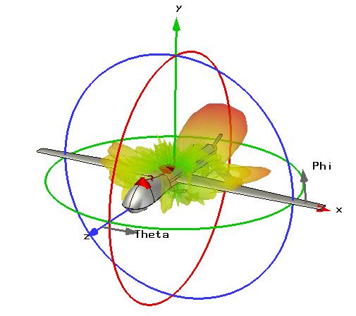
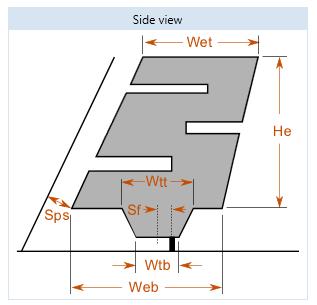
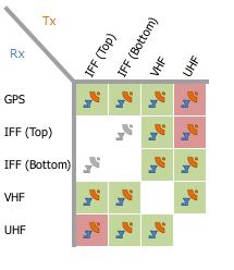
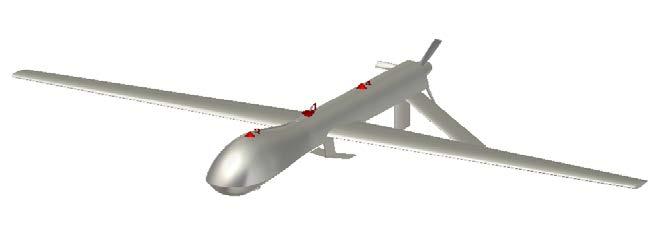
10 Predator Co-Site Analysis GPS elliptical patch GHz UHF blade 320 MHz VHF blade MHz IFF2 monopole MHz IFF1 monopole MHz
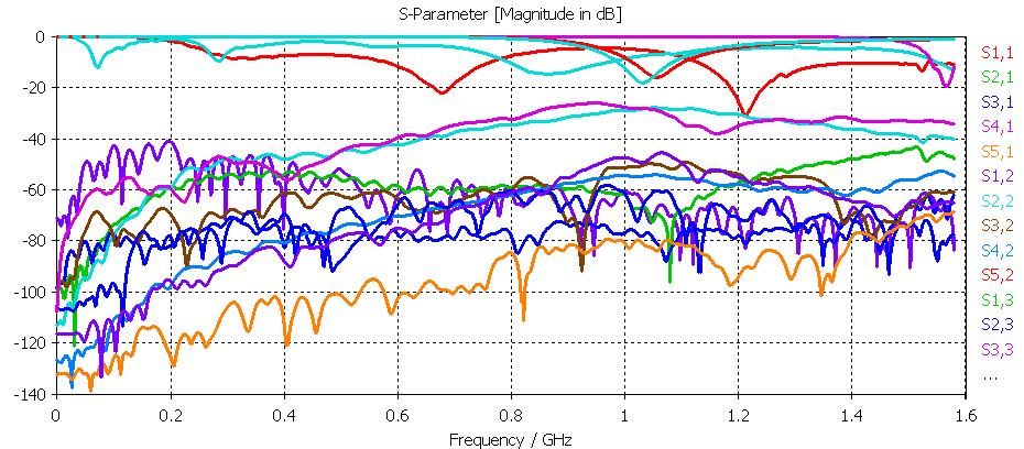
11 Broadband Multi-Port Coupling


12 Installed Patterns 60 MHz 320 MHz 1.06 GHz 1.06 GHz GHz


13 Delcross EMIT Co-Site Tool Tx Emissions Antenna Coupling Rx Vulnerability Software framework for managing system performance data, simulating intra-system EMI effects and mitigating EMI issues Component Characteristics
14 Conclusion Emit is a system management tool Multi-fidelity quality inputs can be used EMI prediction can start at early level of project As input fidelity increases, so do the EMI prediction
15 Multi-Fidelity Coupling Models Constant Coupling - constant Path Loss - free-space path loss (distance) Path Loss + Gain - computed from the path loss and the antenna gain in the direction between antennas. S-Parameters - wideband coupling from user-supplied S-parameters (from measurements or CST STUDIO SUITE) (db) S-Parameters Fixed Value Path Loss Path Loss & Gain

16 EMIT Library EMIT Library currently provides multiple models of typical radios of interest to military and commercial users Each model is notated with specific details of the system Representative models for outboard components are also provided The Library content will continue to be enhanced and updated Users can create and maintain their own databases of systems and components in custom libraries Libraries can be exported for sharing with other users
Prediction of Co-site interference in complex RF environments
 Prediction of Co-site interference in complex RF environments Frank Demming-Janssen CST AG The Cosite Scenario Multiple RF systems co-located in a common environment Diverse system characteristics Frequency
EMIT. RF Cosite and Coexistence RFI Modeling and Mitigation
 RF Cosite and Coexistence RFI Modeling and Mitigation EMIT provides a powerful new capability to the ANSYS RF Option. It is used to predict radio frequency interference (RFI) in complex environments containing
CHAPTER 6 EMI EMC MEASUREMENTS AND STANDARDS FOR TRACKED VEHICLES (MIL APPLICATION)
") 147 CHAPTER 6 EMI EMC MEASUREMENTS AND STANDARDS FOR TRACKED VEHICLES (MIL APPLICATION) 6.1 INTRODUCTION The electrical and electronic devices, circuits and systems are capable of emitting the electromagnetic
147 CHAPTER 6 EMI EMC MEASUREMENTS AND STANDARDS FOR TRACKED VEHICLES (MIL APPLICATION) 6.1 INTRODUCTION The electrical and electronic devices, circuits and systems are capable of emitting the electromagnetic
An Innovative Signal Distribution System That Allows EMI-Free Communications For Navy Ships
 Liberty University DigitalCommons@Liberty University Faculty Publications and Presentations School of Engineering and Computational Sciences 11-2008 An Innovative Signal Distribution System That Allows
Unclassified Distribution A: Unlimited Public Release
 IMPACT OF INADVERTENT ELECTROMAGNETIC EMISSIONS ON ORGANIC VEHICLES THAT AFFECT THE TACTICAL COMMUNICATIONS OPERATING BANDS By Erick Ortiz and Frank A. Bohn US ARMY CERDEC Antennas & Spectrum Analysis
Information on the Evaluation of VHF and UHF Terrestrial Cross-Border Frequency Coordination Requests
 Issue 1 May 2013 Spectrum Management and Telecommunications Technical Bulletin Information on the Evaluation of VHF and UHF Terrestrial Cross-Border Frequency Coordination Requests Aussi disponible en
REVERBERATION CHAMBER FOR EMI TESTING
 1 REVERBERATION CHAMBER FOR EMI TESTING INTRODUCTION EMI Testing 1. Whether a product is intended for military, industrial, commercial or residential use, while it must perform its intended function in
TETRA Tx Test Solution
 Product Introduction TETRA Tx Test Solution Signal Analyzer Reference Specifications ETSI EN 300 394-1 V3.3.1(2015-04) / Part1: Radio ETSI TS 100 392-2 V3.6.1(2013-05) / Part2: Air Interface May. 2016
NUMERICAL METHODOLOGY FOR THE EMI RISK ASSESSMENT OF VEHICULAR ANTENNAS
 NUMERICAL METHODOLOGY FOR THE EMI RISK ASSESSMENT OF VEHICULAR ANTENNAS Alberto Buttiglieri EMEA Product Development Electrical Electronics Unit Audio & Telematics Darmstadt, Germany Content Automotive
EMC Evaluation at Green Bank: Emissions and Shield Effectiveness
 EMC Evaluation at Green Bank: Emissions and Shield Effectiveness National Radio Astronomy Observatory Carla Beaudet Green Bank RFI Group Leader Emissions Evaluation: Standards ITU-R RA.769 specifies (typical)
Differential and Single Ended Elliptical Antennas for GHz Ultra Wideband Communication
 Differential and Single Ended Elliptical Antennas for 3.1-1.6 GHz Ultra Wideband Communication Johnna Powell Anantha Chandrakasan Massachusetts Institute of Technology Microsystems Technology Laboratory
Waves and Devices Chapter of IEEE Phoenix
 Waves and Devices Chapter of IEEE Phoenix Rotor Blade Modulation November 19, 2014 Ron Lavin Assoc. Technical Fellow The Boeing Company Mesa, Arizona ronald.o.lavin@boeing.com Contents Introduction to
Advanced Digital Receiver
 Advanced Digital Receiver MI-750 FEATURES Industry leading performance with up to 4 M samples per second 135 db dynamic range and -150 dbm sensitivity Optimized timing for shortest overall test time Wide
EMC Overview. What is EMC? Why is it Important? Case Studies. Examples of calculations used in EMC. EMC Overview 1
 EMC Overview What is EMC? Why is it Important? Case Studies. Examples of calculations used in EMC. EMC Overview 1 What Is EMC? Electromagnetic Compatibility (EMC): The process of determining the interaction
MINIMIZING SITE INTERFERENCE
 MINIMIZING SITE INTERFERENCE CHAPTER 8 This chapter provides information on preventing radio frequency (RF) interference at a communications site. The following topics are included: Interference Protection
EMC cases study. Antonio Ciccomancini Scogna, CST of America CST COMPUTER SIMULATION TECHNOLOGY
 EMC cases study Antonio Ciccomancini Scogna, CST of America antonio.ciccomancini@cst.com Introduction Legal Compliance with EMC Standards without compliance products can not be released to the market Failure
EMC Amplifiers Going Beyond the Basics to Ensure Successful Immunity Tests
 EMC Amplifiers Going Beyond the Basics to Ensure Successful Immunity Tests Paul Denisowski, Application Engineer Broadband amplifiers are used to generate the high field strengths required by EMC radiated
EMI and its Implications in Multi-Radio Integration. Harry Skinner Principal Engineer Corporate Technology Group Intel Corporation
 EMI and its Implications in Multi-Radio Integration Harry Skinner Principal Engineer Corporate Technology Group Intel Corporation November 15 th 2007 Agenda Background Problem Statement EMI / Platform
MULTILINK LT ENGLISH USER S MANUAL
 MULTILINK LT ENGLISH USER S MANUAL Chapter 1. Installation. 1.1. Safety Rules Please read the safety rules carefully before installing this equipment. 1.- Respect ventilation slots of this equipment.
2. ETSO 2C40c#3 VHF Omni-directional Ranging (VOR) Equipment
 Equipment") Deviation request #96 for an ETSO approval for CS-ETSO applicable to Airborne VHF Omni-directional Ranging (VOR) Equipment (ETSO-2C40c) Consultation Paper 1. Introductory note The hereby presented deviation
Deviation request #96 for an ETSO approval for CS-ETSO applicable to Airborne VHF Omni-directional Ranging (VOR) Equipment (ETSO-2C40c) Consultation Paper 1. Introductory note The hereby presented deviation
Designing Next-Generation AESA Radar Part 2: Individual Antenna Design
 Design Designing Next-Generation AESA Radar Part 2: Individual Antenna Design Figure 8: Antenna design Specsheet user interface showing the electrical requirements input (a), physical constraints input
~W~~~ Laboratory Accreditation Program
 ~ ~.en) National Voluntary ~W~~~ Laboratory Accreditation Program SCOPE OF ACCREDITATION TO ISO/IEC 17025:2005 Dayton T. Brown, Inc. 1195 Church Street Bohemia, NY 11716 Ms. Mary Alice Der Aris Phone:
The equipment will provide up to 50W RF output power in the MHz band.
 19 September 2007 FAA Spectrum Engineering Division 800 Independence Avenue SW Washington, DC 20591 Dear Mr. Frazier, Please be advised that we shall be making an application to the Federal Communications
RF System Aspects for SDR. A Tutorial. Dr. Ruediger Leschhorn, Rohde & Schwarz 29. November 2011
 RF System Aspects for SDR A Tutorial Dr. Ruediger Leschhorn, Rohde & Schwarz 29. November 2011 Content Radio System Some Basics Link Budget Cosite Examples Desensitization Blocking, Transmitter Noise,
INTRODUCTION OF RADIO MICROPHONE APPLICATIONS IN THE FREQUENCY RANGE MHz
 European Radiocommunications Committee (ERC) within the European Conference of Postal and Telecommunications Administrations (CEPT) INTRODUCTION OF RADIO MICROPHONE APPLICATIONS IN THE FREQUENCY RANGE
Implications of Spectrum Management for the Air Force. Paul J Kolodzy, PhD Kolodzy Consulting, LLC
 Implications of Spectrum Management for the Air Force Paul J Kolodzy, PhD Kolodzy Consulting, LLC Studies of the RF Spectrum DoD Defense Science Board, Army Science Board US Gov t FCC (SPTF), WH/DoC Non-Gov
Quotient Associates Ltd RA AY CR3 CONTENTS
 CONTENTS 1 Outdoor Environment...3 1.1 About this document...3 1.2 Introduction...3 1.3 Scenario Description...4 1.3.1 Home and Office Scenario 1 - Urban Railway...4 1.3.2 Home and Office Scenario 2 -
9. MAXIMUM CONDUCTED OUTPUT POWER SPECTRAL DENSITY
 9. MAXIMUM CONDUCTED OUTPUT POWER SPECTRAL DENSITY 9.1. MEASUREMENT PROCEDURE (1). Connect EUT RF output port to the Spectrum Analyzer through an RF attenuator (2). Set the EUT Work on the top, the middle
NMEA Training Overview
 NMEA Training Overview NMEA offers 4 classroom installer training courses Basic Marine Electronics Installer (MEI) Basic NMEA 2000 Network Installer Basic Marine Electronics Installer (MEI) Advanced NMEA
TDOA-Based Localization Using Distributed Sensors Based on Commodity Hardware. EW Europe 2017 London
 TDOA-Based Localization Using Distributed Sensors Based on Commodity Hardware EW Europe 2017 London Dana Christen dc@decodio.com Agenda 1. TDoA: introduction and principle 2. Workflow overview 3. Hardware
Calibration and Validation for Automotive EMC
 Calibration and Validation for Automotive EMC Wolfgang Müllner Patrick Preiner Alexander Kriz Seibersdorf Labor GmbH 2444 Seibersdorf, Austria http://rf.seibersdorf-laboratories.at rf@seibersdorf-laboratories.at
Modular High Power Ku-Band Polarisation Devices for Space Applications. Philipp Kohl
 Modular High Power Ku-Band Polarisation Devices for Space Applications Philipp Kohl 28-29.04.2015 Outline Motivation Mission Scenarios Investigated Polarisation Devices Polarisation Device Principle Requirements
Debugging EMI Using a Digital Oscilloscope. Dave Rishavy Product Manager - Oscilloscopes
 Debugging EMI Using a Digital Oscilloscope Dave Rishavy Product Manager - Oscilloscopes 06/2009 Nov 2010 Fundamentals Scope Seminar of DSOs Signal Fidelity 1 1 1 Debugging EMI Using a Digital Oscilloscope
Radio compliance test
 Training Course on radio measurement June 2016 Radio compliance test Presented by: Karim Loukil & Afef Bohli Page 1 Radio equipement An electrical or electronic product or an interface that intentionally
INTRODUCTION TO CONDUCTED EMISSION
 IEEE EMC Chapter - Hong Kong Section EMC Seminar Series - All about EMC Testing and Measurement Seminar 2 INTRODUCTION TO CONDUCTED EMISSION By Duncan FUNG 18 April 2015 TOPICS TO BE COVERED Background
Communications IPT Ku-Band Antenna UAV Optimization Trade Study Preliminary Rev D February 17, Advanced Tech Engineering, Inc. Frank A.
 Communications IPT Ku-Band Antenna UAV Optimization Trade Study Preliminary Rev D February 17, 2009 Advanced Tech Engineering, Inc. Frank A. Lucchesi Advanced Tech Engineering, Inc This document contains
Trees, vegetation, buildings etc.
 EMC Measurements Test Site Locations Open Area (Field) Test Site Obstruction Free Trees, vegetation, buildings etc. Chamber or Screened Room Smaller Equipments Attenuate external fields (about 100dB) External
GAJET, a DRDC Evaluation Testbed for Navigation Electronic Warfare. Michel Clénet
 GAJET, a DRDC Evaluation Testbed for Navigation Electronic Warfare Michel Clénet Outline Introduction CRPA project at DRDC Ottawa GAJET: An Evaluation Test bed for GPS Anti-Jam System An AJ simulation
radar target generator RTG
 radar target generator RTG Rf target injection for primary radar The RTG (Radar Target Generator) is part of the RASS-S test equipment suite and is designed to generate primary radar returns. It can be
STACKED PATCH MIMO ANTENNA ARRAY FOR C-BAND APPLICATIONS
 STACKED PATCH MIMO ANTENNA ARRAY FOR C-BAND APPLICATIONS Ayushi Agarwal Sheifali Gupta Amanpreet Kaur ECE Department ECE Department ECE Department Thapar University Patiala Thapar University Patiala Thapar
Wireless Power Transmission for Electric Vehicles WPT(EV) A brief overview
 A brief overview") Wireless Power Transmission for Electric Vehicles WPT(EV) A brief overview Topics What is the amateur service? What is WPT(EV)? What plans are there for WPT(EV)? What are the technical characteristics
Wireless Power Transmission for Electric Vehicles WPT(EV) A brief overview Topics What is the amateur service? What is WPT(EV)? What plans are there for WPT(EV)? What are the technical characteristics
WHITE PAPER. Hybrid Beamforming for Massive MIMO Phased Array Systems
 WHITE PAPER Hybrid Beamforming for Massive MIMO Phased Array Systems Introduction This paper demonstrates how you can use MATLAB and Simulink features and toolboxes to: 1. Design and synthesize complex
Applying for a Fixed-to-Mobile Short Term/Temporary Radio Licence Spectrum Management System
 Applying for a Fixed-to-Mobile Short Term/Temporary Radio Licence 1) You must login to your online Web Profile on the Spectrum Management System website: https://smssgs.ic.gc.ca/login/auth 2) After logging
EMC Near-field Probes + Wideband Amplifier
 1 Introduction The H20, H10, H5 and E5 are magnetic field (H) and electric field (E) probes for radiated emissions EMC precompliance measurements. The probes are used in the near field of sources of electromagnetic
UWB Antennas & Measurements. Gabriela Quintero MICS UWB Network Meeting 11/12/2007
 UWB Antennas & Measurements Gabriela Quintero MICS UWB Network Meeting 11/12/27 Outline UWB Antenna Analysis Frequency Domain Time Domain Measurement Techniques Peak and Average Power Measurements Spectrum
OEM PRODUCTS WIRELESS WORLD LOCAL SOLUTION
 OEM PRODUCTS 2008 www.satel.com 2 M3 The M3 is a small and light-weight radio modem designed for integration into the user s terminal equipment. The modem and transceiver are enclosed in a steel or aluminium
AMPLIFIER RESEARCH... APPLICATION NOTE: 23
 AMPLIFIER RESEARCH... APPLICATION NOTE: 23 PRODUCTS THAT PROVIDE 200 V/m CW OR PM AT A DISTANCE OF 1 METER 1 The Amplifier / Antenna / Cell combinations shown in Table 1 provide various means of generating
APPENDIX A TEST PLOTS. (Model: 15Z970)
") APPENDIX A APPENDIX A TEST PLOTS (Model: 15Z970) APPENDIX A-Page 1 of 36 TABLE OF CONTENTS A.1 6dB BANDWIDTH MEASUREMENT... 2 A.1.1 6dB Bandwidth Result... 2 A.1.2 Measurement Plots... 3 A.2 MAXIMUM PEAK
APPENDIX A APPENDIX A TEST PLOTS (Model: 15Z970) APPENDIX A-Page 1 of 36 TABLE OF CONTENTS A.1 6dB BANDWIDTH MEASUREMENT... 2 A.1.1 6dB Bandwidth Result... 2 A.1.2 Measurement Plots... 3 A.2 MAXIMUM PEAK
Why Single Dish? Darrel Emerson NRAO Tucson. NAIC-NRAO School on Single-Dish Radio Astronomy. Green Bank, August 2003.
 Why Single Dish? Darrel Emerson NRAO Tucson NAIC-NRAO School on Single-Dish Radio Astronomy. Green Bank, August 2003. Why Single Dish? What's the Alternative? Comparisons between Single-Dish, Phased Array
Advanced Test Equipment Rentals ATEC (2832) CNE III Comparison Noise Emitter
 CNE III Comparison Noise Emitter") Established 1981 Advanced Test Equipment Rentals www.atecorp.com 800-404-ATEC (2832) CNE III Comparison Noise Emitter Product Technical Information CNE III Comparison Noise Emitter The industry standard
Established 1981 Advanced Test Equipment Rentals www.atecorp.com 800-404-ATEC (2832) CNE III Comparison Noise Emitter Product Technical Information CNE III Comparison Noise Emitter The industry standard
EMC aspects associated to 5G networks
 EMC aspects associated to 5G networks ETSI TC-EE/ITU-T SG5 Workshop on Towards Setting Environmental Requirements for 5G Beniamino Gorini 23-11-2017 1 Outline 1. Scenario of present EMC requirements 2.
Test Methods and Standards for RF Based Emergency Equipment
 Test Methods and Standards for RF Based Emergency Equipment Precision Indoor Personnel Location and Tracking for Emergency Responders International Technology Workshop August 1-, 011 Kate Remley, William
RADIATION PATTERNS. The half-power (-3 db) beamwidth is a measure of the directivity of the antenna.
 beamwidth is a measure of the directivity of the antenna.") RADIATION PATTERNS The radiation pattern is a graphical depiction of the relative field strength transmitted from or received by the antenna. Antenna radiation patterns are taken at one frequency, one
RADIATION PATTERNS The radiation pattern is a graphical depiction of the relative field strength transmitted from or received by the antenna. Antenna radiation patterns are taken at one frequency, one
Keysight Technologies UWB Antenna Measurements with the 20 GHz E5071C ENA Network Analyzer. Application Note
 Keysight Technologies UWB Antenna Measurements with the 20 GHz E5071C ENA Network Analyzer Application Note Introduction Ultra-wideband (UWB) is a rapidly growing technology that is used to transmit information
MODERN AND future wireless systems are placing
 IEEE TRANSACTIONS ON MICROWAVE THEORY AND TECHNIQUES 1 Wideband Planar Monopole Antennas With Dual Band-Notched Characteristics Wang-Sang Lee, Dong-Zo Kim, Ki-Jin Kim, and Jong-Won Yu, Member, IEEE Abstract
Proposal for ACP requirements
 AMCP WG D9-WP/13 Proposal for requirements Presented by the IATA member Prepared by F.J. Studenberg Rockwell-Collins SUMMARY The aim of this paper is to consider what level of is achievable by a VDL radio
Dynamic Sciences International, Inc. Detection with Direction
 Dynamic Sciences International, Inc Detection with Direction CORPORATE OVERVIEW WHO WE ARE Dynamic Sciences International, Inc. (DSII) is a public corporation Serving customers worldwide since 1972. DSII
VideoComm Technologies. Wireless Video Solutions
 VideoComm Technologies Wireless Video Solutions Agenda 1. 1. Introduction 2. 2. Understanding Transmitter & Receiver 3. 3. Available Frequencies 4. 4. Frequency Challenges Agenda 5. 5. Making Product Recommendations
An Introduction to EMC Testing (what can be done with scopes) Vincent Lascoste EMC Product Manager - RSF
 Vincent Lascoste EMC Product Manager - RSF") An Introduction to EMC Testing (what can be done with scopes) Vincent Lascoste EMC Product Manager - RSF Definition of ElectroMagnetic Compatibility (EMC) EMC is defined as: "The ability of devices and
An Introduction to EMC Testing (what can be done with scopes) Vincent Lascoste EMC Product Manager - RSF Definition of ElectroMagnetic Compatibility (EMC) EMC is defined as: "The ability of devices and
5G System Concept Seminar. RF towards 5G. Researchers: Tommi Tuovinen, Nuutti Tervo & Aarno Pärssinen
 04.02.2016 @ 5G System Concept Seminar RF towards 5G Researchers: Tommi Tuovinen, Nuutti Tervo & Aarno Pärssinen 5.2.2016 2 Outline 5G challenges for RF Key RF system assumptions Channel SNR and related
Design and Optimization of Microstrip Patch Antenna for Satellite Applications
 Design and Optimization of Microstrip Patch Antenna for Satellite Applications Budati Suresh Kumar, Assistant Professor, ECE Department, Chirala Engineering College, CHIRALA balaji2547@gmail.com ABSTRACT
EECE 301 Signals & Systems Prof. Mark Fowler
 EECE 301 Signals & Systems Prof. Mark Fowler Note Set #16 C-T Signals: Using FT Properties 1/12 Recall that FT Properties can be used for: 1. Expanding use of the FT table 2. Understanding real-world concepts
Understanding the Unintended Antenna Behavior of a Product
 Understanding the Unintended Antenna Behavior of a Product Colin E. Brench Southwest Research Institute Electromagnetic Compatibility Research and Testing colin.brench@swri.org Radiating System Source
Design for Guaranteed EMC Compliance
 Clemson Vehicular Electronics Laboratory Reliable Automotive Electronics Automotive EMC Workshop April 29, 2013 Design for Guaranteed EMC Compliance Todd Hubing Clemson University EMC Requirements and
EMC Simulation of Consumer Electronic Devices
 of Consumer Electronic Devices By Andreas Barchanski Describing a workflow for the EMC simulation of a wireless router, using techniques that can be applied to a wide range of consumer electronic devices.
Electromagnetic Interference (EMI) Assessments, Findings, & Solutions
 Assessments, Findings, & Solutions") Electromagnetic Interference (EMI) Assessments, Findings, & Solutions 22 February 2017 HF Industry Association Spring 2017 Meeting 1 EMI Experience LWI EMI assessment locations over the past 5 to 7 years
Electromagnetic Interference (EMI) Assessments, Findings, & Solutions 22 February 2017 HF Industry Association Spring 2017 Meeting 1 EMI Experience LWI EMI assessment locations over the past 5 to 7 years
EMC simulation addresses ECU validation issues
 EMC simulation addresses ECU validation issues A more straightforward validation of electromagnetic compatibility can be achieved by combining tools. By Stefan Heimburger, Andreas Barchanski, and Thorsten
Politecnico di Torino. Porto Institutional Repository
 Politecnico di Torino Porto Institutional Repository [Proceeding] Integrated miniaturized antennas for automotive applications Original Citation: Vietti G., Dassano G., Orefice M. (2010). Integrated miniaturized
HF Transmit/Receive Broadband System XB 2900
 Data sheet HF Transmit/Receive Broadband System XB 2900 Especially designed for naval operational environment Full HF frequency band (2 MHz to 30 MHz) for voice, data, and ALE operation Flexible system
Why Single Dish? Darrel Emerson NRAO Tucson. NAIC-NRAO School on Single-Dish Radio Astronomy. Green Bank, August 2003.
 Why Single Dish? Darrel Emerson NRAO Tucson NAIC-NRAO School on Single-Dish Radio Astronomy. Green Bank, August 2003. Why Single Dish? What's the Alternative? Comparisons between Single-Dish, Phased Array
3GPP TS V8.0.0 ( )
") TS 36.104 V8.0.0 (2007-12) Technical Specification 3rd Generation Partnership Project; Technical Specification Group Radio Access Network; Evolved Universal Terrestrial Radio Access (E-UTRA); Base Station
TS 36.104 V8.0.0 (2007-12) Technical Specification 3rd Generation Partnership Project; Technical Specification Group Radio Access Network; Evolved Universal Terrestrial Radio Access (E-UTRA); Base Station
Report Demonstration Field Test
 Report Demonstration Field Test The device under test: Genesys Resonant Active Tunable (GRAT) antenna Designer-owner: GENESYS LTD Model code name: GRAT-C-27V3 Device Purpose: RF Transmitting-Receiving
Using measured fields as field sources in computational electromagnetic (CEM) solvers
 solvers") Using measured fields as field sources in computational electromagnetic (CEM) solvers Presenter: Lucia Scialacqua lucia.scialacqua@microwavevision.com Content Domain decomposition techniques have been
Using measured fields as field sources in computational electromagnetic (CEM) solvers Presenter: Lucia Scialacqua lucia.scialacqua@microwavevision.com Content Domain decomposition techniques have been
How EMxpert Diagnoses Board-Level EMC Design Issues
 Application Report EMxpert July 2011 - Cédric Caudron How EMxpert Diagnoses Board-Level EMC Design Issues ABSTRACT EMxpert provides board-level design teams with world-leading fast magnetic very-near-field
Why/When I need a Spectrum Analyzer. Jan 12, 2017
 Why/When I need a Jan 12, 2017 Common Questions What s the difference of Oscilloscope and Spectrum Analysis Almost all Oscilloscope has FFT for a spectrum view, why I need a spectrum analyzer? When shall
Why Single Dish? Why Single Dish? Darrel Emerson NRAO Tucson
 Why Single Dish? Darrel Emerson NRAO Tucson Why Single Dish? What's the Alternative? Comparisons between Single-Dish, Phased Array & Interferometers Advantages and Disadvantages of Correlation Interferometer
RIGOL Presents: New Solutions for Affordable Pre- Compliance Testing
 Product Demo RIGOL Presents: New Solutions for Affordable Pre- Compliance Testing Wednesday, April 27, 2016 2:20 pm - 2:35 pm EDT Chris Armstrong Chris Armstrong is the Director of Product Marketing &
Determining The Size Of Cabinet Apertures For Effectively Mitigating Radiated Emissions. By David Norte Thursday, April 7 th, 2005
 The EMC, Signal And Power Integrity Institute Presents Determining The Size Of Cabinet Apertures For Effectively Mitigating Radiated Emissions By David Norte Thursday, April 7 th, 2005 1 Motivation For
Co-Existence of UMTS900 and GSM-R Systems
 Asdfadsfad Omnitele Whitepaper Co-Existence of UMTS900 and GSM-R Systems 30 August 2011 Omnitele Ltd. Tallberginkatu 2A P.O. Box 969, 00101 Helsinki Finland Phone: +358 9 695991 Fax: +358 9 177182 E-mail:
Ready for RED. Radio Equipment Directive. General Introduction. / RED. Christian Reimer
 Ready for RED Radio Equipment Directive General Introduction www.rohde-schwarz.com / RED Christian Reimer RED: Radio Equipment Directive 2014/53/EU: mandatory since June 2017 Radio Equipment Directive
MITIGATING INTERFERENCE ON AN OUTDOOR RANGE
 MITIGATING INTERFERENCE ON AN OUTDOOR RANGE Roger Dygert MI Technologies Suwanee, GA 30024 rdygert@mi-technologies.com ABSTRACT Making measurements on an outdoor range can be challenging for many reasons,
REPORT ITU-R M Characteristics of broadband wireless access systems operating in the land mobile service for use in sharing studies
 Rep. ITU-R M.2116 1 REPORT ITU-R M.2116 Characteristics of broadband wireless access systems operating in the land mobile service for use in sharing studies (Questions ITU-R 1/8 and ITU-R 7/8) (2007) 1
RD988 Super Version. Intelligent Super Repeater
 RD988 Super Version Intelligent Super Repeater DMR Simulcast and DMR Trunking upgradable IP Multi-site Connection Digital telephone Interconnection RDAC Remote Management Software RD988 Super Version Intelligent
Electromagnetic Compatibility at Green Bank: Evaluation and Mitigation
 Electromagnetic Compatibility at Green Bank: Evaluation and Mitigation National Radio Astronomy Observatory John Ford Green Bank Electronics Division Head Carla Beaudet Green Bank RFI Engineer Emissions
Quick Site Testing with the 8800SX
 Quick Site Testing with the 8800SX Site Testing with the 8800SX Basic Tests 5 site testing involves several tests to verify site operation. NOTE: This is not intended to be a complete commissioning procedure.
Solving Large Multi-Scale Problems in CST STUDIO SUITE
 Solving Large Multi-Scale Problems in CST STUDIO SUITE An Aircraft Application M. Kunze, Z. Reznicek, I. Munteanu, P. Tobola, F. Wolfheimer Motivation I New A/C concepts (fly-by-wire, all electric aircraft,
TV combiners. Combiners with mask filters for digital operation TYPE DESCRIPTION
 TV combiners TYPE DESCRIPTION 1 2-3 4-5 1-Number of inputs: 2PX - two inputs 3PX - three inputs 4PX - four inputs 5PX - five inputs 6PX - six inputs 7PX - seven inputs 8PX - eight inputs 9PX - nine inputs
TECHNICAL NOTES. MT-4 Radio Systems. TN247 VR-4E VHF MT-4E Receiver. Specifications. Models Available. Receiver Operating Frequency
 MADE IN CANADA TN247 VR-4E VHF MT-4E Receiver USB CNTL BUS A D RECEIVER FREQUENCY (MHz) SQ. DISABLE NORM OFF REF IN RF IN The VR-4E VHF receiver is an FM radio module capable of analog operation in 12.5
2015 Interference 101. Robin Jackman Application Engineer
 2015 Interference 101 Robin Jackman Application Engineer Agenda What is Interference Introduction Definitions Spectrum Analyzer Concepts Concepts, Controls, Displays Making good measurements Measuring
 1.0 Job Description 1.1 Client Information This EUT has been tested at the request of: Company: Spectronic Denmark A/S Contact: John Herlev Telephone: 011 45 863-87-222 Fax: 011 45 863-87-704 Email: jhe@spectronic-denmark.com
Random Walk Technique: Measuring EME in Below-Deck Complex Cavities
 NAVAL SURFACE WARFARE CENTER DAHLGREN DIVISION Random Walk Technique: Measuring EME in Below-Deck Complex Cavities Presented by: Mike Slocum & Greg Tait E 3 Assessment & Evaluation Branch (Q52) 22 August
RECOMMENDATION ITU-R P ATTENUATION IN VEGETATION. (Question ITU-R 202/3)
") Rec. ITU-R P.833-2 1 RECOMMENDATION ITU-R P.833-2 ATTENUATION IN VEGETATION (Question ITU-R 2/3) Rec. ITU-R P.833-2 (1992-1994-1999) The ITU Radiocommunication Assembly considering a) that attenuation
Rec. ITU-R P.833-2 1 RECOMMENDATION ITU-R P.833-2 ATTENUATION IN VEGETATION (Question ITU-R 2/3) Rec. ITU-R P.833-2 (1992-1994-1999) The ITU Radiocommunication Assembly considering a) that attenuation
RECOMMENDATION ITU-R F.1097 * (Question ITU-R 159/9)
") Rec. ITU-R F.1097 1 RECOMMENDATION ITU-R F.1097 * INTERFERENCE MITIGATION OPTIONS TO ENHANCE COMPATIBILITY BETWEEN RADAR SYSTEMS AND DIGITAL RADIO-RELAY SYSTEMS (Question ITU-R 159/9) Rec. ITU-R F.1097
Rec. ITU-R F.1097 1 RECOMMENDATION ITU-R F.1097 * INTERFERENCE MITIGATION OPTIONS TO ENHANCE COMPATIBILITY BETWEEN RADAR SYSTEMS AND DIGITAL RADIO-RELAY SYSTEMS (Question ITU-R 159/9) Rec. ITU-R F.1097
The sensitivity test of 2.45GHz RFID active tag
 Journal of Physics: Conference Series PAPER OPEN ACCESS The sensitivity test of 2.45GHz RFID active tag To cite this article: Xiaoli Shi et al 208 J. Phys.: Conf. Ser. 087 052034 View the article online
EMC analysis workflow
 EMC analysis workflow Antonio Ciccomancini Scogna, CST of America antonio.ciccomancini@cst.com EMC/EMI Applications Emissions Susceptibility E3 Typical Emissions Issues 1 2 Image courtesy of Johnson Controls
Short-Range Ultra- Wideband Systems
 Short-Range Ultra- Wideband Systems R. A. Scholtz Principal Investigator A MURI Team Effort between University of Southern California University of California, Berkeley University of Massachusetts, Amherst
The CubeSTAR Project. Design of a Prototype Communication System for the CubeSTAR Nano-satellite. Master presentation by Johan Tresvig 24th Aug.
 Design of a Prototype Communication System for the CubeSTAR Nano-satellite Master presentation by Johan Tresvig 24th Aug. 2010 The CubeSTAR Project Student satellite project at the University of Oslo Scientific
NXDN Signal and Interference Contour Requirements An Empirical Study
 NXDN Signal and Interference Contour Requirements An Empirical Study Icom America Engineering December 2007 Contents Introduction Results Analysis Appendix A. Test Equipment Appendix B. Test Methodology
Cover note to draft ECC/DEC/(06)AA on UWB
AA on UWB") Cover note to draft ECC/DEC/(06)AA on UWB UWB public consultation Introductory text For the purpose of the public consultation on the draft ECC Decision on Devices using UWB technologies in the bands below
Cover note to draft ECC/DEC/(06)AA on UWB UWB public consultation Introductory text For the purpose of the public consultation on the draft ECC Decision on Devices using UWB technologies in the bands below
MTR3000 Base Station
 MTR3000 Base Station Martin Rogat Radio Product Manager The information contained herein is provided for information purposes poses only and is intended only to outline Motorola s s presently anticipated