Preface. If you have any problems for learning, please contact us at We will do our best to help you solve the problem.
|
|
|
- Alexandrina Anderson
- 5 years ago
- Views:
Transcription
1
2 Preface Adeept is a technical service team of open source software and hardware. Dedicated to applying the Internet and the latest industrial technology in open source area, we strive to provide best hardware support and software service for general makers and electronic enthusiasts around the world. We aim to create infinite possibilities with sharing. No matter what field you are in, we can lead you into the electronic world and bring your ideas into reality. This is an entry-level learning kit for Arduino. Some common electronic components and sensors are included. Through the learning, you will get a better understanding of Arduino, and be able to make fascinating works based on Arduino. If you have any problems for learning, please contact us at support@adeept.com. We will do our best to help you solve the problem
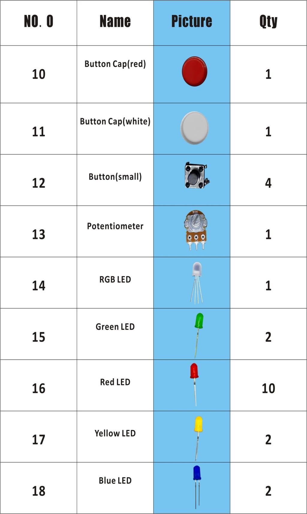
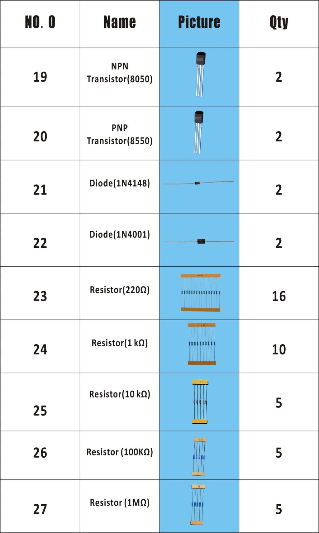
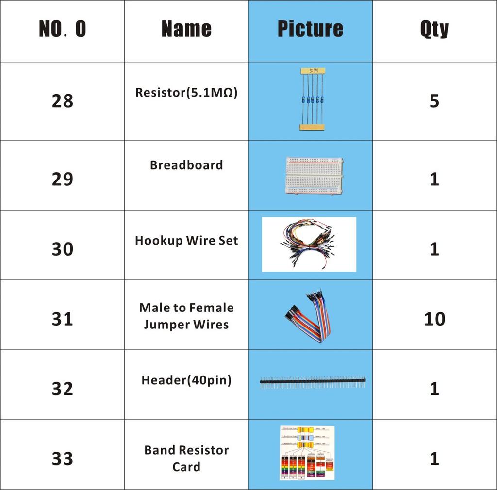
3 Component List - 3 -
4 - 4 -
5 - 5 -
6 - 6 -
7 Content About Arduino Lesson 1 Blinking LED Lesson 2 Controlling an LED with a button Lesson 3 Tilt Switch Lesson 4 Active Buzzer Lesson 5 Controlling Relay Lesson 6 LED Flowing Lights Lesson 7 Breathing LED Lesson 8 Controlling a RGB LED by PWM Lesson 9 Serial Port Lesson 10 Controlling Servo motor Lesson 11 LCD1602 display Lesson 12 Using a thermistor to measure the temperature Lesson 13 Photoresistor
8 About Arduino What is Arduino? Arduino is an open-source electronics platform based on easy-to-use hardware and software. It's intended for anyone making interactive projects. ARDUINO BOARD Arduino senses the environment by receiving inputs from many sensors, and affects its surroundings by controlling lights, motors, and other actuators. ARDUINO SOFTWARE You can tell your Arduino what to do by writing code in the Arduino programming language and using the Arduino development environment. Before the development of Arduino program, the first thing you have to do is to install Arduino IDE software. The software provides you with the basic development environment that is required for developing Arduino program. You need the following URL to download Arduino IDE: For different operating system platforms, the way of using Arduino IDE is different. Please refer to the following links: Windows User: Mac OS X User: Linux User: For more detailed information about Arduino IDE, please refer to the following link:
 and low")
9 Lesson 1 Blinking LED Overview In this tutorial, we will start the journey of learning Arduino UNO. In the first lesson, we will learn how to make a LED blinking. Requirement - 1* Arduino UNO - 1* USB Cable - 1* 220Ω Resistor - 1* LED - 1* Breadboard - 2* Jumper Wires Principle In this lesson, we will program the Arduino's GPIO output high(+5v) and low level(0v), and then make the LED which is connected to the Arduino s GPIO flicker with a certain frequency. 1. What is the LED? The LED is the abbreviation of light emitting diode. It is usually made of gallium arsenide, gallium phosphide semiconductor materials. The LED has two electrodes, a positive electrode and a negative electrode, it will light only when a forward current passes, and it can be red, blue, green or yellow light, etc. The color of light depends on the materials it was made. In general, the drive current for LED is 5-20mA. Therefore, in reality it usually needs an extra resistor for current limitation so as to protect the LED
10 2. What is the resistor? The main function of the resistor is to limit current. In the circuit, the character R represents resistor, and the unit of resistor is ohm(ω). The band resistor is used in this experiment. A band resistor is one whose surface is coated with some particular color through which the resistance can be identified directly. There are two methods for connecting LED to Arduino s GPIO: 1 As shown in the schematic diagram above, the anode of LED is connected to Arduino s GPIO via a resistor, and the cathode of LED is connected to the ground(gnd). When the GPIO output high level, the LED is on; when the GPIO output low level, the LED is off. The size of the current-limiting resistor is calculated as follows: 5~20mA current is required to make an LED on, and the out put voltage of the Arduino UNO s GPIO is 5V, so we can get the resistance: R = U / I = 5V / (5~20mA) = 250Ω~1KΩ Since the LED has a certain resistance, thus we choose a 220ohm resistor. 2 As shown in the schematic diagram above, the anode of LED is connected to VCC(+5V), and the cathode of LED is connected to the Arduino s GPIO. When the GPIO output low level, the LED is on; when the GPIO output high level, the LED is off. The experiment is based on method 1, we select Arduino's D8 pin to control the LED. When the Arduino s D8 pin is programmed to output high level, then the LED will be on, next delay for the amount of time, and then programmed the D8 pin to low level to make the LED off. Continue to perform the above process, you can get a blinking LED
11 3. Key functions: setup() The setup() function is called when a sketch starts. Use it to initialize variables, pin modes, start using libraries, etc. The setup function will only run once, after each powerup or reset of the Arduino board. loop() After creating a setup() function, which initializes and sets the initial values, the loop() function does precisely what its name suggests, and loops consecutively, allowing your program to change and respond. Use it to actively control the Arduino board. pinmode() Configures the specified pin to behave either as an input or an output. As of Arduino 1.0.1, it is possible to enable the internal pullup resistors with the mode INPUT_PULLUP. Additionally, the INPUT mode explicitly disables the internal pullups. digitalwrite() Write a HIGH or a LOW value to a digital pin. If the pin has been configured as an OUTPUT with pinmode(), its voltage will be set to the corresponding value: 5V (or 3.3V on 3.3V boards) for HIGH, 0V (ground) for LOW. If the pin is configured as an INPUT, digitalwrite() will enable (HIGH) or disable (LOW) the internal pullup on the input pin. It is recommended to set the pinmode() to INPUT_PULLUP to enable the internal pull-up resistor. delay() Pauses the program for the amount of time (in miliseconds) specified as parameter. (There are 1000 milliseconds in a second.) Procedures 1. Build the circuit - 4 -
 {")
12 2. Program /*********************************************************** File name: 01_blinkingLed.ino Description: Lit LED, let LED blinks. Website: Author: Tom Date: 2015/05/02 ***********************************************************/ int ledpin=8; //definition digital 8 pins as pin to control the LED void setup() { pinmode(ledpin,output); //Set the digital 8 port mode, OUTPUT: Output mode } void loop() { digitalwrite(ledpin,high); //HIGH is set to about 5V PIN8 delay(1000); //Set the delay time, 1000 = 1S digitalwrite(ledpin,low); //LOW is set to about 5V PIN8 delay(1000); //Set the delay time, 1000 = 1S } - 5 -

13 3. Compile the program and upload to Arduino UNO board Now, you can see the LED is blinking
14 Lesson 2 Controlling an LED with a button Overview In this lesson, we will learn how to detect the state of a button, and then toggle the state of LED based on the state of the button. Requirement - 1* Arduino UNO - 1* USB Cable - 1* Button - 1* LED - 1* 10KΩ Resistor - 1* 220Ω Resistor - 1* Breadboard - Several Jumper Wires Principle 1. Button Buttons are a common component used to control electronic devices. They are usually used as switches to connect or disconnect circuits. Although buttons come in a variety of sizes and shapes, the one used in this experiment will be a 12mm button as shown in the following pictures. Pins pointed out by the arrows of same color are meant to be connected. The button we used is a normally open type button. The two contacts of a button is in the off state under the normal conditions, only when the button is pressed they are closed. The schematic diagram we used is as follows: - 7 -
15 The button jitter must be happen in the process of using. The jitter waveform is as the flowing picture: Each time you press the button, the Arduino will think you have pressed the button many times due to the jitter of the button. We must to deal with the jitter of buttons before we use the button. We can through the software programming method to remove the jitter of buttons, and you can use a capacitance to remove the jitter of buttons. We introduce the software method. First, we detect whether the level of button interface is low level or high level. When the level we detected is low level, 5~10 MS delay is needed, and then detect whether the level of button interface is low or high. If the signal is low, we can confirm that the button is pressed once. You can also use a 0.1 uf capacitance to clean up the jitter of buttons. The schematic diagram is shown in below: 2. interrupt Hardware interrupts were introduced as a way to reduce wasting the processor's valuable time in polling loops, waiting for external events. They - 8 -
16 may be implemented in hardware as a distinct system with control lines, or they may be integrated into the memory subsystem. 3. Key functions: attachinterrupt(interrupt, ISR, mode) Specifies a named Interrupt Service Routine (ISR) to call when an interrupt occurs. Replaces any previous function that was attached to the interrupt. Most Arduino boards have two external interrupts: numbers 0 (on digital pin 2) and 1 (on digital pin 3). Generally, an ISR should be as short and fast as possible. If your sketch uses multiple ISRs, only one can run at a time, other interrupts will be ignored (turned off) until the current one is finished. as delay() and millis() both rely on interrupts, they will not work while an ISR is running. delaymicroseconds(), which does not rely on interrupts, will work as expected. Syntax attachinterrupt(pin, ISR, mode) Parameters pin: the pin number ISR: the ISR will be called when the interrupt occurs; this function must take no parameters and return nothing. This function is sometimes referred to as an interrupt service routine. mode: defines when the interrupt should be triggered. Four constants are predefined as valid values: -LOW to trigger the interrupt whenever the pin is low, -CHANGE to trigger the interrupt whenever the pin changes value -RISING to trigger when the pin goes from low to high, -FALLING for when the pin goes from high to low. digitalread() Reads the value from a specified digital pin, either HIGH or LOW. Syntax digitalread(pin) Parameters pin: the number of the digital pin you want to read (int) Returns HIGH or LOW delaymicroseconds(us) - 9 -
17 Pauses the program for the amount of time (in microseconds) specified as parameter. There are a thousand microseconds in a millisecond, and a million microseconds in a second. Currently, the largest value that will produce an accurate delay is This could change in future Arduino releases. For delays longer than a few thousand microseconds, you should use delay() instead. Syntax delaymicroseconds(us) Parameters us: the number of microseconds to pause (unsigned int) Returns None Procedures 1. Build the circuit 2. Program 3. Compile the program and upload to Arduino UNO board When you press the button, you can see the state of the LED will be toggled. (ON->OFF,OFF->ON)

18 Summary Through this lesson, you should have learned how to use the Arduino UNO detects an external button state, and then toggle the state of LED relying on the state of the button detected before

19 Lesson 3 Tilt Switch Overview In this lesson, we will learn how to use the tilt switch and change the state of an LED by changing the angle of tilt switch. Requirement - 1* Arduino UNO - 1* USB Cable - 1* Tilt Switch - 1* LED - 1* 220Ω Resistor - 1* Breadboard - Several Jumper Wires Principle The tilt switch is also called the ball switch. When the switch is tilted in the appropriate direction, the contacts will be connected, tilting the switch the opposite direction causes the metallic ball to move away from that set of contacts, thus breaking that circuit. Procedures 1. Build the circuit
20 2. Program /*********************************************************** File name: 03_tiltSwitch.ino Description: Tilt switches to control the LED light on or off Website: Author: Tom Date: 2015/05/02 ***********************************************************/ int ledpin=11; //definition digital 11 pins as pin to control the //LED int tiltswitchpin=7; //Set the digital 7 to tilt switch interface int val; //Define variable val void setup() { pinmode(ledpin,output); //Define small lights interface for the //output interface pinmode(tiltswitchpin,input_pullup);//define the tilt switch //interface for input interface } void loop() { val=digitalread(tiltswitchpin);//read the number seven level value is //assigned to val if(val==low) //Detect tilt switch is disconnected, the //tilt switch when small lights go out { digitalwrite(ledpin,low);} //Output low, LED OFF else //Detection of tilt switch is conduction, //tilt the little lights up when the switch conduction { digitalwrite(ledpin,high);} //Output high, LED ON } 3. Compile the program and upload to Arduino UNO board Now, when you lean the breadboard at a certain angle, you will see the state of LED is changed

21 Summary In this lesson, we have learned the principle and application of the tilt switch. Tilt switch is a very simple electronic component, but simple device can often make something interesting
 - 1* Breadboard - Several Jumper Wires Principle A buzzer or beeper is an audio signaling")

22 Lesson 4 Active Buzzer Overview In this lesson, we will learn how to program the Arduino to make an active buzzer sound. Requirement - 1* Arduino UNO - 1* USB cable - 1* Active buzzer - 1* 1 kω Resistor - 1* NPN Transistor (S8050) - 1* Breadboard - Several Jumper Wires Principle A buzzer or beeper is an audio signaling device. As a type of electronic buzzer with integrated structure, which use DC power supply, are widely used in computers, printers, photocopiers, alarms, electronic toys, automotive electronic equipments, telephones, timers and other electronic products for voice devices. Buzzers can be categorized as active and passive buzzers (See the following pictures). When you place the pins of buzzers upward, you can see that two buzzers are different, the buzzer that green circuit board exposed is the passive buzzer. In this study, the buzzer we used is active buzzer. Active buzzer will sound as long as the power supply. We can program to make the Arduino output alternating high and low level, so that the buzzer sounds

23 A slightly larger current is needed to make a buzzer sound. However, the output current of Arduino s GPIO is weak, so we need a transistor to drive the buzzer. The main function of transistor is blowing up the voltage or current. The transistor can also be used to control the circuit conduction or deadline. And the transistor is divided into two kinds, one kind is NPN, for instance, the S8050 we provided; another kind is PNP transistor such as the S8550 we provided. The transistor we used is as shown in below: There are two driving circuit for the buzzer: Figure1 Figure2 Figure 1: Set the Arduino GPIO as a high level, the transistor S8050 will conduct, and then the buzzer will sound; set the Arduino GPIO as low level, the transistor S8050 will cut off, then the buzzer will stop

24 Figure 2: Set the Arduino GPIO as low level, the transistor S8550 will conduct, and the buzzer will sound; set the Arduino GPIO as a high level, the transistor S8550 will cut off, then the buzzer will stop. Procedures 1. Build the circuit 2. Program 3. Compile the program and upload to Arduino UNO board Now, you should be able to hear the sound of the buzzer

25 Summary By learning this lesson, we have mastered the basic principle of the buzzer and the transistor. We also learned how to program the Arduino and then control the buzzer. I hope you can use what you have learned in this lesson to do some interesting things
26 Lesson 5 Controlling Relay Overview In this lesson, we will learn how to control a relay to cut off or connect a circuit. Requirement - 1* Arduino UNO - 1* USB Cable - 1* NPN Transistor (S8050) - 1* 1K Resistor - 1* 1N4001 Diode - 1* 220Ω Resistor - 1* Relay - 1* LED - 1* Breadboard - Several Jumper Wires Principle A relay is an electrically operated switch. It is generally used in automatic control circuit. Actually, it is an "automatic switch" which uses low current to control high current. It plays a role of automatic regulation, security protection and circuit switch. When an electric current is passed through the coil it generates a magnetic field that activates the armature, and the consequent movement of the movable contact(s) either makes or breaks (depending upon construction) a connection with a fixed contact. If the set of contacts was closed when the relay was de-energized, then the movement opens the contacts and breaks the connection, and vice versa if the contacts were open. When the current to the coil is switched off, the armature is returned by a force, approximately half as strong as the magnetic force, to its relaxed position. Usually this force is provided by a spring, but gravity is also used commonly in industrial motor starters. Most relays are manufactured to operate quickly. In a low-voltage application this reduces noise; in a high voltage or current application it reduces arcing. When the coil is energized with direct current, a diode is often placed across the coil to dissipate the energy from the collapsing magnetic field at deactivation, which would otherwise generate a voltage spike dangerous to semiconductor circuit components

27 Procedures 1. Build the circuit 2. Program 3. Compile the program and upload to Arduino UNO board When the set of contacts was closed, the LED will be lit up; when the set of contacts was broke, the LED will go out

28 Summary By learning this lesson, you have already known the basic principle of the relay, and you can also use the relay to do some creative applications
29 Lesson 6 LED Flowing Lights Overview In the first class, we have learned how to make an LED blink by programming the Arduino. Today, we will use the Arduino to control 8 LEDs, so that 8 LEDs showing the result of flowing. Requirement - 1* Arduino UNO - 1* USB Cable - 8* LED - 8* 220Ω Resistor - 1* Breadboard - Several Jumper Wires Principle The principle of this experiment is very simple. It is very similar with the first class. Key function: for statements The for statement is used to repeat a block of statements enclosed in curly braces. An increment counter is usually used to increment and terminate the loop. The for statement is useful for any repetitive operation, and is often used in combination with arrays to operate on collections of data/pins. There are three parts to the for loop header: for (initialization; condition; increment) { //statement(s); }

30 The initialization happens first and exactly once. Each time through the loop, the condition is tested; if it's true, the statement block, and the increment is executed, then the condition is tested again. When the condition becomes false, the loop ends. Procedures 1. Build the circuit 2. Program 3. Compile the program and upload to Arduino UNO board Now, you should see 8 LEDs are lit in sequence from the right green one to the

31 left, next from the left to the right one. And then repeat the above phenomenon. Summary Through this simple and fun experiment, we have learned more skilled programming about the Arduino. In addition, you can also modify the circuit and code we provided to achieve even more dazzling effect
32 Lesson 7 Breathing LED Overview In this lesson, we will learn how to program the Arduino to generate PWM signal. And use the PWM square-wave signal control an LED gradually becomes brighter and then gradually becomes dark like the animal s breathing. Requirement - 1* Arduino UNO - 1* USB Cable - 1* LED - 1* 220Ω Resistor - 1* Breadboard - Several Jumper Wires Principle Pulse Width Modulation, or PWM, is a technique for getting analog results with digital means. Digital control is used to create a square wave, a signal switched between on and off. This on-off pattern can simulate voltages in between full on (5 Volts) and off (0 Volts) by changing the portion of the time the signal spends on versus the time that the signal spends off. The duration of "on time" is called the pulse width. To get varying analog values, you change, or modulate, that pulse width. If you repeat this on-off pattern fast enough with an LED for example, the result is as if the signal is a steady voltage between 0 and 5v controlling the brightness of the LED. In the graphic below, the green lines represent a regular time period. This duration or period is the inverse of the PWM frequency. In other words, with Arduino's PWM frequency at about 500Hz, the green lines would measure 2 milliseconds each. A call to analogwrite() is on a scale of 0-255, such that analogwrite(255) requests a 100% duty cycle (always on), and analogwrite(127) is a 50% duty cycle (on half the time) for example
33 Key function: analogwrite() Writes an analog value (PWM wave) to a pin. Can be used to light an LED at varying brightnesses or drive a motor at various speeds. After a call to analogwrite(), the pin will generate a steady square wave of the specified duty cycle until the next call to analogwrite() (or a call to digitalread() or digitalwrite() on the same pin). You do not need to call pinmode() to set the pin as an output before calling analogwrite(). Syntax analogwrite(pin, value) Parameters pin: the pin to write to. value: the duty cycle: between 0 (always off) and 255 (always on). Returns nothing Procedures 1. Build the circuit

34 2. Program 3. Compile the program and upload to Arduino UNO board. Now, you should see the LED gradually from dark to brighter, and then from brighter to dark, continuing to repeat the process, its rhythm like the animal's breathing
35 Summary By learning this lesson, I believe that you have understood the basic principles of the PWM, and mastered the PWM programming on the Arduino platform
36 Lesson 8 Controlling a RGB LED by PWM Overview In this lesson, we will program the Arduino for RGB LED control, and make RGB LED emits a various of colors of light. Requirement - 1* Arduino UNO - 1* USB Cable - 1* RGB LED - 3* 220Ω Resistor - 1* Breadboard - Several Jumper Wires Principle RGB LEDs consist of three LEDs. Each LED actually has one red, one green and one blue light. These three colored LEDs are capable of producing any color. Tri-color LEDs with red, green, and blue emitters, in general using a four-wire connection with one common lead (anode or cathode). These LEDs can have either common anode or common cathode leads. What we used in this experiment is the common anode RGB LED. The longest pin is the common anode of three LEDs. The pin is connected to the +5V pin of the Arduino, and the three remaining pins are connected to the Arduino s D9, D10, D11 pins through a current limiting resistor. In this way, we can control the color of RGB LED by 3-channel PWM signal

37 Procedures 1. Build the circuit 2. Program 3. Compile the program and upload to Arduino UNO board Now, you can see the RGB LED emitting red, green, blue, yellow, white and purple light, then the RGB LED will be off, each state continues 1s, after repeating the above procedure

38 Summary By learning this lesson, I believe you have already known the principle and the programming of RGB LED. I hope you can use your imagination to achieve even more cool ideas based on this lesson
39 Lesson 9 Serial Port Overview In this lesson, we will program the Arduino UNO to achieve function of send and receive data through the serial port. The Arduino receiving data which send from PC, and then controlling an LED according to the received data, then return the state of LED to the PC's serial port monitor. Requirement - 1* Arduino UNO - 1* USB Cable - 1* LED - 1* 220Ω Resistor - 1* Breadboard - Several Jumper Wires Principle 1. Serial ports Used for communication between the Arduino board and a computer or other devices. All Arduino boards have at least one serial port (also known as a UART or USART). It communicates on digital pins 0 (RX) and 1 (TX) as well as with the computer via USB. Thus, if you use these functions, you cannot also use pins 0 and 1 for digital input or output. You can use the Arduino environment's built-in serial monitor to communicate with an Arduino board. Click the serial monitor button in the toolbar and select the same baud rate used in the call to begin(). To use these pins to communicate with your personal computer, you will need an additional USB-to-serial adaptor, as they are not connected to the UNO's USB-to-serial adaptor. To use them to communicate with an external TTL serial device, connect the TX pin to your device's RX pin, the RX to your device's TX pin, and the ground of your UNO to your device's ground. (Don't connect these pins directly to an RS232 serial port; they operate at +/- 12V and can damage your Arduino board.) 2. Key function begin() Sets the data rate in bits per second (baud) for serial data transmission. For
40 communicating with the computer, use one of these rates: 300, 1200, 2400, 4800, 9600, 14400, 19200, 28800, 38400, 57600, or You can, however, specify other rates - for example, to communicate over pins 0 and 1 with a component that requires a particular baud rate. Syntax Serial.begin(speed) Parameters speed: in bits per second (baud) - long Returns nothing print() Prints data to the serial port as human-readable ASCII text. This command can take many forms. Numbers are printed using an ASCII character for each digit. Floats are similarly printed as ASCII digits, defaulting to two decimal places. Bytes are sent as a single character. Characters and strings are sent as is. For example: Serial.print(78) gives 78 Serial.print( ) gives 1.23 Serial.print('N') gives N Serial.print( Hello world. ) gives Hello world. An optional second parameter specifies the base (format) to use; permitted values are BIN (binary, or base 2), OCT (octal, or base 8), DEC (decimal, or base 10), HEX (hexadecimal, or base 16). For floating point numbers, this parameter specifies the number of decimal places to use. For example: Serial.print(78, BIN) gives Serial.print(78, OCT) gives 116 Serial.print(78, DEC) gives 78 Serial.print(78, HEX) gives 4E Serial.println( , 0) gives 1 Serial.println( , 2) gives 1.23 Serial.println( , 4) gives You can pass flash-memory based strings to Serial.print() by wrapping them with F(). For example : Serial.print(F( Hello World )) To send a single byte, use Serial.write(). Syntax Serial.print(val)
41 Serial.print(val, format) Parameters val: the value to print - any data type format: specifies the number base (for integral data types) or number of decimal places (for floating point types) Returns byte print() will return the number of bytes written, though reading that number is optional println() Prints data to the serial port as human-readable ASCII text followed by a carriage return character (ASCII 13, or ' r') and a newline character (ASCII 10, or ' n'). This command takes the same forms as Serial.print(). Syntax Serial.println(val) Serial.println(val, format) Parameters val: the value to print - any data type format: specifies the number base (for integral data types) or number of decimal places (for floating point types) Returns byte println() will return the number of bytes written, though reading that number is optional read() Reads incoming serial data. read() inherits from the Stream utility class. Syntax Serial.read() Parameters None Returns the first byte of incoming serial data available (or -1 if no data is available) - int Procedures 1. Build the circuit


42 2. Program 3. Compile the program and upload to Arduino UNO board Open the port monitor, and then select the appropriate baud rate according to the program. Now, if you send a character 1 or 0 on the serial monitor, the state of LED will be lit or gone out

43 Summary Through this lesson, you should have understood that the computer can send data to Arduino UNO via the serial port, and then control the state of LED. I hope you can use your head to make more interesting things based on this lesson
44 Lesson 10 Controlling Servo motor Overview In this lesson, we will introduce a new electronic device (Servo) to you, and tell you how to control it with the Arduino UNO. Requirement - 1* Arduino UNO - 1* USB Cable - 1* Servo - Several Jumper Wires Principle 1. Servo motor The servo motor have three wires: power, ground, and signal. The power wire is typically red, and should be connected to the 5V pin on the Arduino board. The ground wire is typically black or brown and should be connected to a ground pin on the Arduino board. The signal pin is typically yellow, orange or white and should be connected to a digital pin on the Arduino board. Note the servo motor draw considerable power, so if you need to drive more than one or two, you'll probably need to power them from a separate supply (i.e. not the +5V pin on your Arduino). Be sure to connect the grounds of the Arduino and external power supply together. 2. Servo library This library allows an Arduino board to control RC (hobby) servo motors. Servos have integrated gears and a shaft that can be precisely controlled. Standard servos allow the shaft to be positioned at various angles, usually between 0 and 180 degrees. Continuous rotation servos allow the rotation of the shaft to be set to various speeds. 3. Key functions: attach() Attach the Servo variable to a pin. Note that in Arduino 0016 and earlier, the Servo library supports only servos on only two pins: 9 and 10. Syntax servo.attach(pin)
 Parameters servo: a variable of type Servo pin: the number of the pin that the servo is attached to min (optional): the pulse width, in microseconds, corresponding to the")
45 servo.attach(pin, min, max) Parameters servo: a variable of type Servo pin: the number of the pin that the servo is attached to min (optional): the pulse width, in microseconds, corresponding to the minimum (0-degree) angle on the servo (defaults to 544) max (optional): the pulse width, in microseconds, corresponding to the maximum (180-degree) angle on the servo (defaults to 2400) Procedures 1. Build the circuit 2. Program 3. Compile the program and upload to Arduino UNO board Now, you should see the servo rotate 180 degrees, and then rotate in opposite direction

46 Summary By learning this lesson, you should have known that the Arduino provided a servo library to control a servo. By using the servo library, you can easily control a servo. Just enjoy your imagination and make some interesting applications
47 Lesson 11 LCD1602 display Overview In this lesson, we will learn how to use a character display device LCD1602 on the Arduino platform. First, we make the LCD1602 display a string "Hello Geeks!" scrolling,then display Adeept and static. Requirement - 1* Arduino UNO - 1* USB Cable - 1* LCD1602-1* 10KΩ Potentiometer - 1* Breadboard - Several Jumper Wires Principle LCD1602 is a kind of character LCD display. The LCD has a parallel interface, meaning that the microcontroller has to manipulate several interface pins at once to control the display. The interface consists of the following pins: A register select (RS) pin that controls where in the LCD's memory you're writing data to. You can select either the data register, which holds what goes on the screen, or an instruction register, which is where the LCD's controller looks for instructions on what to do next. A Read/Write (R/W) pin that selects reading mode or writing mode An Enable pin that enables writing to the registers 8 data pins (D0-D7). The state of these pins (high or low) are the bits that you're writing to a register when you write, or the values when you read. There's also a display contrast pin (Vo), power supply pins (+5V and Gnd) and LED Backlight (Bklt+ and BKlt-) pins that you can use to power the LCD, control the display contrast, and turn on or off the LED backlight respectively. The process of controlling the display involves putting the data that form the image of what you want to display into the data registers, then putting instructions in the instruction register. The LiquidCrystal Library simplifies this for you so you don't need to know the low-level instructions. The Hitachi-compatible LCDs can be controlled in two modes: 4-bit or 8-bit
48 The 4-bit mode requires seven I/O pins from the Arduino, while the 8-bit mode requires 11 pins. For displaying text on the screen, you can do most everything in 4-bit mode, so example shows how to control a 2x16 LCD in 4-bit mode. A potentiometer, informally a pot, is a three-terminal resistor with a sliding or rotating contact that forms an adjustable voltage divider. If only two terminals are used, one end and the wiper, it acts as a variable resistor or rheostat. Key function: begin() Specifies the dimensions (width and height) of the display. Syntax lcd.begin(cols, rows) Parameters lcd: a variable of type LiquidCrystal cols: the number of columns that the display has rows: the number of rows that the display has setcursor() Position the LCD cursor; that is, set the location at which subsequent text written to the LCD will be displayed. Syntax lcd.setcursor(col, row) Parameters lcd: a variable of type LiquidCrystal col: the column at which to position the cursor (with 0 being the first column) row: the row at which to position the cursor (with 0 being the first row) scrolldisplayleft() Scrolls the contents of the display (text and cursor) one space to the left. Syntax lcd.scrolldisplayleft() Parameters lcd: a variable of type LiquidCrystal Example scrolldisplayleft() and scrolldisplayright() See also scrolldisplayright() print() Prints text to the LCD
 Parameters lcd: a variable of type LiquidCrystal data: the data to print (char, byte, int, long, or string) BASE (optional): the base in which to print numbers: BIN for binary (base")
49 Syntax lcd.print(data) lcd.print(data, BASE) Parameters lcd: a variable of type LiquidCrystal data: the data to print (char, byte, int, long, or string) BASE (optional): the base in which to print numbers: BIN for binary (base 2), DEC for decimal (base 10), OCT for octal (base 8), HEX for hexadecimal (base 16). Returns byte print() will return the number of bytes written, though reading that number is optional clear() Clears the LCD screen and positions the cursor in the upper-left corner. Syntax lcd.clear() Parameters lcd: a variable of type LiquidCrystal Procedures 1. Build the circuit 2. Program
50 3. Compile the program and upload to Arduino UNO board Now, you can see the string "Hello Geeks!" is shown on the LCD1602 scrolling, and then the string "Adeept" and " is displayed on the LCD1602 static. Summary I believe that you have already mastered the driver of LCD1602 through this lesson. I hope you can make something more interesting base on this lesson and the previous lesson learned
51 Lesson 12 Using a thermistor to measure Overview the temperature In this lesson, we will learn how to use a thermistor to collect temperature by programming Arduino. The information which a thermistor collects temperature is displayed on the LCD1602. Requirement - 1* Arduino UNO - 1* USB Cable - 1* LCD1602-1* 10KΩ Potentiometer - 1* 10KΩ Resistor - 1* Thermistor - 1* Breadboard - Several Jumper Wires Principle A thermistor is a type of resistor whose resistance varies significantly with temperature, more so than in standard resistors. We are using MF52 NTC thermistor type. BTC thermistor is usually used as a temperature sensor. MF52 thermistor key parameters: B-parameter: resistor:10kω. The relationship between the resistance of thermistor and temperature is as follows: : the resistance of thermistor at temperature T1 : The nominal resistance of thermistor at room temperature T2; : ; : It is one of the important parameters of thermistor;
 + degrees Celsius; After transforming the above equation, we can get to the following formula: Procedures 1. Build the circuit 2. Program 3.")
52 : the Kelvin temperature that you want to measure. : At the condition of room temperature 25 (298.15K), the standard resistance of MF52 thermistor is 10K; Kelvin temperature = (absolute temperature) + degrees Celsius; After transforming the above equation, we can get to the following formula: Procedures 1. Build the circuit 2. Program 3. Compile the program and upload to Arduino UNO board Now, you can see the temperature which is collected by thermistor on the LCD

53 Summary By learning this lesson, I believe you have learned to use a thermistor to measure temperature. Next, you can use a thermistor to produce some interesting applications
54 Lesson 13 Photoresistor Overview In this lesson, we will learn how to measure the light intensity by photoresistor and make the measurement result displayed on the LCD1602. Requirement - 1* Arduino UNO - 1* USB Cable - 1* LCD1602-1* Photoresistor - 1* 10KΩ Resistor - 1* 10KΩ Potentiometer - 1* Breadboard - Several Jumper Wires Principle A photoresistor is a light-controlled variable resistor. The resistance of a photoresistor decreases with the increasing incident light intensity; in other words, it exhibits photoconductivity. A photoresistor can be applied in light-sensitive detector circuits. A photoresistor is made of a high resistance semiconductor. In the dark, a photoresistor can have a resistance as high as a few megohms (MΩ), while in the light, a photoresistor can have a resistance as low as a few hundred ohms. If incident light on a photoresistor exceeds a certain frequency, photons absorbed by the semiconductor give bound electrons enough energy to jump into the conduction band. The resulting free electrons (and their hole partners) conduct electricity, thereby lowering resistance. The resistance range and sensitivity of a photoresistor can substantially differ among dissimilar devices. Moreover, unique photoresistors may react substantially differently to photons within certain wavelength bands. The schematic diagram of this experiment is shown below:
55 With the increase of the light intensity, the resistance of photoresistor will be decreased. The voltage of GPIO port in the above figure will become high. Procedures 1. Build the circuit 2. Program 3. Compile the program and upload to Arduino UNO board Now, when you try to block the light towards the photoresistor, you will find that the value displayed on the LCD1602 will be reduced. Otherwise, when you use a powerful light to irradiate the photoresistor, the value displayed on the LCD1602 will be increased

56 Summary By learning this lesson, we have learned how to detect surrounding light intensity with the photoresistor. You can play your own wisdom, and make more originality based on this experiment and the former experiment

57
HAW-Arduino. Sensors and Arduino F. Schubert HAW - Arduino 1
 HAW-Arduino Sensors and Arduino 14.10.2010 F. Schubert HAW - Arduino 1 Content of the USB-Stick PDF-File of this script Arduino-software Source-codes Helpful links 14.10.2010 HAW - Arduino 2 Report for
Coding with Arduino to operate the prosthetic arm
 Setup Board Install FTDI Drivers This is so that your RedBoard will be able to communicate with your computer. If you have Windows 8 or above you might already have the drivers. 1. Download the FTDI driver
For this exercise, you will need a partner, an Arduino kit (in the plastic tub), and a laptop with the Arduino programming environment.
, and a laptop with the Arduino programming environment.") Physics 222 Name: Exercise 6: Mr. Blinky This exercise is designed to help you wire a simple circuit based on the Arduino microprocessor, which is a particular brand of microprocessor that also includes
Physics 222 Name: Exercise 6: Mr. Blinky This exercise is designed to help you wire a simple circuit based on the Arduino microprocessor, which is a particular brand of microprocessor that also includes
Arduino Microcontroller Processing for Everyone!: Third Edition / Steven F. Barrett
 Arduino Microcontroller Processing for Everyone!: Third Edition / Steven F. Barrett Anatomy of a Program Programs written for a microcontroller have a fairly repeatable format. Slight variations exist
Attribution Thank you to Arduino and SparkFun for open source access to reference materials.
 Attribution Thank you to Arduino and SparkFun for open source access to reference materials. Contents Parts Reference... 1 Installing Arduino... 7 Unit 1: LEDs, Resistors, & Buttons... 7 1.1 Blink (Hello
J. La Favre Using Arduino with Raspberry Pi February 7, 2018
 As you have already discovered, the Raspberry Pi is a very capable digital device. Nevertheless, it does have some weaknesses. For example, it does not produce a clean pulse width modulation output (unless
TWEAK THE ARDUINO LOGO
 TWEAK THE ARDUINO LOGO Using serial communication, you'll use your Arduino to control a program on your computer Discover : serial communication with a computer program, Processing Time : 45 minutes Level
Microcontrollers and Interfacing
 Microcontrollers and Interfacing Week 07 digital input, debouncing, interrupts and concurrency College of Information Science and Engineering Ritsumeikan University 1 this week digital input push-button
Lab 2: Blinkie Lab. Objectives. Materials. Theory
 Lab 2: Blinkie Lab Objectives This lab introduces the Arduino Uno as students will need to use the Arduino to control their final robot. Students will build a basic circuit on their prototyping board and
1. Introduction to Analog I/O
 EduCake Analog I/O Intro 1. Introduction to Analog I/O In previous chapter, we introduced the 86Duino EduCake, talked about EduCake s I/O features and specification, the development IDE and multiple examples
Lecture 4: Basic Electronics. Lecture 4 Brief Introduction to Electronics and the Arduino
 Lecture 4: Basic Electronics Lecture 4 Page: 1 Brief Introduction to Electronics and the Arduino colintan@nus.edu.sg Lecture 4: Basic Electronics Page: 2 Objectives of this Lecture By the end of today
EE-110 Introduction to Engineering & Laboratory Experience Saeid Rahimi, Ph.D. Labs Introduction to Arduino
 EE-110 Introduction to Engineering & Laboratory Experience Saeid Rahimi, Ph.D. Labs 10-11 Introduction to Arduino In this lab we will introduce the idea of using a microcontroller as a tool for controlling
MAKEVMA502 BASIC DIY KIT WITH ATMEGA2560 FOR ARDUINO USER MANUAL
 BASIC DIY KIT WITH ATMEGA2560 FOR ARDUINO USER MANUAL USER MANUAL 1. Introduction To all residents of the European Union Important environmental information about this product This symbol on the device
Objectives: Learn what an Arduino is and what it can do Learn what an LED is and how to use it Be able to wire and program an LED to blink
 Objectives: Learn what an Arduino is and what it can do Learn what an LED is and how to use it Be able to wire and program an LED to blink By the end of this session: You will know how to use an Arduino
Arduino Digital Out_QUICK RECAP
 Arduino Digital Out_QUICK RECAP BLINK File> Examples>Digital>Blink int ledpin = 13; // LED connected to digital pin 13 // The setup() method runs once, when the sketch starts void setup() // initialize
FABO ACADEMY X ELECTRONIC DESIGN
 ELECTRONIC DESIGN MAKE A DEVICE WITH INPUT & OUTPUT The Shanghaino can be programmed to use many input and output devices (a motor, a light sensor, etc) uploading an instruction code (a program) to it
Portland State University MICROCONTROLLERS
 PH-315 MICROCONTROLLERS INTERRUPTS and ACCURATE TIMING I Portland State University OBJECTIVE We aim at becoming familiar with the concept of interrupt, and, through a specific example, learn how to implement
MICROCONTROLLERS BASIC INPUTS and OUTPUTS (I/O)
") PH-315 Portland State University MICROCONTROLLERS BASIC INPUTS and OUTPUTS (I/O) ABSTRACT A microcontroller is an integrated circuit containing a processor and programmable read-only memory, 1 which is
PH-315 Portland State University MICROCONTROLLERS BASIC INPUTS and OUTPUTS (I/O) ABSTRACT A microcontroller is an integrated circuit containing a processor and programmable read-only memory, 1 which is
CURIE Academy, Summer 2014 Lab 2: Computer Engineering Software Perspective Sign-Off Sheet
 Lab : Computer Engineering Software Perspective Sign-Off Sheet NAME: NAME: DATE: Sign-Off Milestone TA Initials Part 1.A Part 1.B Part.A Part.B Part.C Part 3.A Part 3.B Part 3.C Test Simple Addition Program
EE 314 Spring 2003 Microprocessor Systems
 EE 314 Spring 2003 Microprocessor Systems Laboratory Project #9 Closed Loop Control Overview and Introduction This project will bring together several pieces of software and draw on knowledge gained in
Basic Microprocessor Interfacing Trainer Lab Manual
 Basic Microprocessor Interfacing Trainer Lab Manual Control Inputs Microprocessor Data Inputs ff Control Unit '0' Datapath MUX Nextstate Logic State Memory Register Output Logic Control Signals ALU ff
Lesson 13. The Big Idea: Lesson 13: Infrared Transmitters
 Lesson Lesson : Infrared Transmitters The Big Idea: In Lesson 12 the ability to detect infrared radiation modulated at 38,000 Hertz was added to the Arduino. This lesson brings the ability to generate
Experiment 1: Robot Moves in 3ft squared makes sound and
 Experiment 1: Robot Moves in 3ft squared makes sound and turns on an LED at each turn then stop where it started. Edited: 9-7-2015 Purpose: Press a button, make a sound and wait 3 seconds before starting
MICROCONTROLLERS BASIC INPUTS and OUTPUTS (I/O)
") PH-315 Portland State University MICROCONTROLLERS BASIC INPUTS and OUTPUTS (I/O) ABSTRACT A microcontroller is an integrated circuit containing a processor and programmable read-only memory, 1 which is
PH-315 Portland State University MICROCONTROLLERS BASIC INPUTS and OUTPUTS (I/O) ABSTRACT A microcontroller is an integrated circuit containing a processor and programmable read-only memory, 1 which is
Electronic Components
 Electronic Components Arduino Uno Arduino Uno is a microcontroller (a simple computer), it has no way to interact. Building circuits and interface is necessary. Battery Snap Battery Snap is used to connect
Sten-Bot Robot Kit Stensat Group LLC, Copyright 2013
 Sten-Bot Robot Kit Stensat Group LLC, Copyright 2013 Legal Stuff Stensat Group LLC assumes no responsibility and/or liability for the use of the kit and documentation. There is a 90 day warranty for the
Computational Crafting with Arduino. Christopher Michaud Marist School ECEP Programs, Georgia Tech
 Computational Crafting with Arduino Christopher Michaud Marist School ECEP Programs, Georgia Tech Introduction What do you want to learn and do today? Goals with Arduino / Computational Crafting Purpose
Lesson 3: Arduino. Goals
 Introduction: This project introduces you to the wonderful world of Arduino and how to program physical devices. In this lesson you will learn how to write code and make an LED flash. Goals 1 - Get to
Disclaimer. Arduino Hands-On 2 CS5968 / ART4455 9/1/10. ! Many of these slides are mine. ! But, some are stolen from various places on the web
 Arduino Hands-On 2 CS5968 / ART4455 Disclaimer! Many of these slides are mine! But, some are stolen from various places on the web! todbot.com Bionic Arduino and Spooky Arduino class notes from Tod E.Kurt!
ZX Distance and Gesture Sensor Hookup Guide
 Page 1 of 13 ZX Distance and Gesture Sensor Hookup Guide Introduction The ZX Distance and Gesture Sensor is a collaboration product with XYZ Interactive. The very smart people at XYZ Interactive have created
Mechatronics Engineering and Automation Faculty of Engineering, Ain Shams University MCT-151, Spring 2015 Lab-4: Electric Actuators
 Mechatronics Engineering and Automation Faculty of Engineering, Ain Shams University MCT-151, Spring 2015 Lab-4: Electric Actuators Ahmed Okasha, Assistant Lecturer okasha1st@gmail.com Objective Have a
Assignments from last week
 Assignments from last week Review LED flasher kits Review protoshields Need more soldering practice (see below)? http://www.allelectronics.com/make-a-store/category/305/kits/1.html http://www.mpja.com/departments.asp?dept=61
PIC Functionality. General I/O Dedicated Interrupt Change State Interrupt Input Capture Output Compare PWM ADC RS232
 PIC Functionality General I/O Dedicated Interrupt Change State Interrupt Input Capture Output Compare PWM ADC RS232 General I/O Logic Output light LEDs Trigger solenoids Transfer data Logic Input Monitor
You'll create a lamp that turns a light on and off when you touch a piece of conductive material
 TOUCHY-FEELY LAMP You'll create a lamp that turns a light on and off when you touch a piece of conductive material Discover : installing third party libraries, creating a touch sensor Time : 5 minutes
CONSTRUCTION GUIDE Capacitor, Transistor & Motorbike. Robobox. Level VII
 CONSTRUCTION GUIDE Capacitor, Transistor & Motorbike Robobox Level VII Capacitor, Transistor & Motorbike In this box, we will understand in more detail the operation of DC motors, transistors and capacitor.
Arduino STEAM Academy Arduino STEM Academy Art without Engineering is dreaming. Engineering without Art is calculating. - Steven K.
 Arduino STEAM Academy Arduino STEM Academy Art without Engineering is dreaming. Engineering without Art is calculating. - Steven K. Roberts Page 1 See Appendix A, for Licensing Attribution information
Module: Arduino as Signal Generator
 Name/NetID: Teammate/NetID: Module: Laboratory Outline In our continuing quest to access the development and debugging capabilities of the equipment on your bench at home Arduino/RedBoard as signal generator.
INA169 Breakout Board Hookup Guide
 Page 1 of 10 INA169 Breakout Board Hookup Guide CONTRIBUTORS: SHAWNHYMEL Introduction Have a project where you want to measure the current draw? Need to carefully monitor low current through an LED? The
CPSC 226 Lab Four Spring 2018
 CPSC 226 Lab Four Spring 2018 Directions. This lab is a quick introduction to programming your Arduino to do some basic internal operations and arithmetic, perform character IO, read analog voltages, drive
Lab 5: Arduino Uno Microcontroller Innovation Fellows Program Bootcamp Prof. Steven S. Saliterman
 Lab 5: Arduino Uno Microcontroller Innovation Fellows Program Bootcamp Prof. Steven S. Saliterman Exercise 5-1: Familiarization with Lab Box Contents Objective: To review the items required for working
Arduino An Introduction
 Arduino An Introduction Hardware and Programming Presented by Madu Suthanan, P. Eng., FEC. Volunteer, Former Chair (2013-14) PEO Scarborough Chapter 2 Arduino for Mechatronics 2017 This note is for those
Sidekick Basic Kit for Arduino V2 Introduction
 Sidekick Basic Kit for Arduino V2 Introduction The Arduino Sidekick Basic Kit is designed to be used with your Arduino / Seeeduino / Seeeduino ADK / Maple Lilypad or any MCU board. It contains everything
.:Twisting:..:Potentiometers:.
 CIRC-08.:Twisting:..:Potentiometers:. WHAT WE RE DOING: Along with the digital pins, the also has 6 pins which can be used for analog input. These inputs take a voltage (from 0 to 5 volts) and convert
CONSTRUCTION GUIDE IR Alarm. Robobox. Level I
 CONSTRUCTION GUIDE Robobox Level I This month s montage is an that will allow you to detect any intruder. When a movement is detected, the alarm will turn its LEDs on and buzz to a personalized tune. 1X
Lab 06: Ohm s Law and Servo Motor Control
 CS281: Computer Systems Lab 06: Ohm s Law and Servo Motor Control The main purpose of this lab is to build a servo motor control circuit. As with prior labs, there will be some exploratory sections designed
Monitoring Temperature using LM35 and Arduino UNO
 Sharif University of Technology Microprocessor Arduino UNO Project Monitoring Temperature using LM35 and Arduino UNO Authors: Sadegh Saberian 92106226 Armin Vakil 92110419 Ainaz Hajimoradlou 92106142 Supervisor:
Setup Download the Arduino library (link) for Processing and the Lab 12 sketches (link).
 for Processing and the Lab 12 sketches (link).") Lab 12 Connecting Processing and Arduino Overview In the previous lab we have examined how to connect various sensors to the Arduino using Scratch. While Scratch enables us to make simple Arduino programs,
Lab 12 Connecting Processing and Arduino Overview In the previous lab we have examined how to connect various sensors to the Arduino using Scratch. While Scratch enables us to make simple Arduino programs,
Rodni What will yours be?
 Rodni What will yours be? version 4 Welcome to Rodni, a modular animatronic animal of your own creation for learning how easy it is to enter the world of software programming and micro controllers. During
Welcome to Arduino Day 2016
 Welcome to Arduino Day 2016 An Intro to Arduino From Zero to Hero in an Hour! Paul Court (aka @Courty) Welcome to the SLMS Arduino Day 2016 Arduino / Genuino?! What?? Part 1 Intro Quick Look at the Uno
Pulse Width Modulation and
 Pulse Width Modulation and analogwrite ( ); 28 Materials needed to wire one LED. Odyssey Board 1 dowel Socket block Wire clip (optional) 1 Female to Female (F/F) wire 1 F/F resistor wire LED Note: The
100UF CAPACITOR POTENTIOMETER SERVO MOTOR MOTOR ARM. MALE HEADER PIN (3 pins) INGREDIENTS
 INGREDIENTS") 05 POTENTIOMETER SERVO MOTOR MOTOR ARM 100UF CAPACITOR MALE HEADER PIN (3 pins) INGREDIENTS 63 MOOD CUE USE A SERVO MOTOR TO MAKE A MECHANICAL GAUGE TO POINT OUT WHAT SORT OF MOOD YOU RE IN THAT DAY Discover:
05 POTENTIOMETER SERVO MOTOR MOTOR ARM 100UF CAPACITOR MALE HEADER PIN (3 pins) INGREDIENTS 63 MOOD CUE USE A SERVO MOTOR TO MAKE A MECHANICAL GAUGE TO POINT OUT WHAT SORT OF MOOD YOU RE IN THAT DAY Discover:
ECE 511: FINAL PROJECT REPORT GROUP 7 MSP430 TANK
 ECE 511: FINAL PROJECT REPORT GROUP 7 MSP430 TANK Team Members: Andrew Blanford Matthew Drummond Krishnaveni Das Dheeraj Reddy 1 Abstract: The goal of the project was to build an interactive and mobile
Experiment #3: Micro-controlled Movement
 Experiment #3: Micro-controlled Movement So we re already on Experiment #3 and all we ve done is blinked a few LED s on and off. Hang in there, something is about to move! As you know, an LED is an output
Arduino Lesson 1. Blink. Created by Simon Monk
 Arduino Lesson 1. Blink Created by Simon Monk Guide Contents Guide Contents Overview Parts Part Qty The 'L' LED Loading the 'Blink' Example Saving a Copy of 'Blink' Uploading Blink to the Board How 'Blink'
School of Engineering Mechatronics Engineering Department. Experim. ment no. 1
 University of Jordan School of Engineering Mechatronics Engineering Department 2010 Mechatronics System Design Lab Experim ment no. 1 PRINCIPLES OF SWITCHING Copyrights' are held by : Eng. Ala' Bata &
LC-10 Chipless TagReader v 2.0 August 2006
 LC-10 Chipless TagReader v 2.0 August 2006 The LC-10 is a portable instrument that connects to the USB port of any computer. The LC-10 operates in the frequency range of 1-50 MHz, and is designed to detect
CMU232 User Manual Last Revised October 21, 2002
 CMU232 User Manual Last Revised October 21, 2002 Overview CMU232 is a new low-cost, low-power serial smart switch for serial data communications. It is intended for use by hobbyists to control multiple
Application Note. Communication between arduino and IMU Software capturing the data
 Application Note Communication between arduino and IMU Software capturing the data ECE 480 Team 8 Chenli Yuan Presentation Prep Date: April 8, 2013 Executive Summary In summary, this application note is
Arduino: Sensors for Fun and Non Profit
 Arduino: Sensors for Fun and Non Profit Slides and Programs: http://pamplin.com/dms/ Nicholas Webb DMS: @NickWebb 1 Arduino: Sensors for Fun and Non Profit Slides and Programs: http://pamplin.com/dms/
Application Note AN 157: Arduino UART Interface to TelAire T6613 CO2 Sensor
 Application Note AN 157: Arduino UART Interface to TelAire T6613 CO2 Sensor Introduction The Arduino UNO, Mega and Mega 2560 are ideal microcontrollers for reading CO2 sensors. Arduino boards are useful
Introduction to Electronics and Breadboarding Circuits
 Introduction to Electronics and Breadboarding Circuits What we're going to learn today: What is an electronic circuit? What kind of power is needed for these projects? What are the fundamental principles
Basic Electronics Course Part 2
 Basic Electronics Course Part 2 Simple Projects using basic components Including Transistors & Pots Following are instructions to complete several electronic exercises Image 7. Components used in Part
Servomotor Control with Arduino Integrated Development Environment. Application Notes. Bingyang Wu Mar 27, Introduction
 Servomotor Control with Arduino Integrated Development Environment Application Notes Bingyang Wu Mar 27, 2015 Introduction Arduino is a tool for making computers that can sense and control more of the
Lecture 6. Interfacing Digital and Analog Devices to Arduino. Intro to Arduino
 Lecture 6 Interfacing Digital and Analog Devices to Arduino. Intro to Arduino PWR IN USB (to Computer) RESET SCL\SDA (I2C Bus) POWER 5V / 3.3V / GND Analog INPUTS Digital I\O PWM(3, 5, 6, 9, 10, 11) Components
smraza Getting Start Guide Contents Arduino IDE (Integrated Development Environment)... 1 Introduction... 1 Install the Arduino Software (IDE)...
... 1 Introduction... 1 Install the Arduino Software (IDE)...") Getting Start Guide Contents Arduino IDE (Integrated Development Environment)... 1 Introduction... 1 Install the Arduino Software (IDE)...1 Introduction... 1 Step 1: Get an Uno R3 and USB cable... 2 Step
Getting Start Guide Contents Arduino IDE (Integrated Development Environment)... 1 Introduction... 1 Install the Arduino Software (IDE)...1 Introduction... 1 Step 1: Get an Uno R3 and USB cable... 2 Step
Lock Cracker S. Lust, E. Skjel, R. LeBlanc, C. Kim
 Lock Cracker S. Lust, E. Skjel, R. LeBlanc, C. Kim Abstract - This project utilized Eleven Engineering s XInC2 development board to control several peripheral devices to open a standard 40 digit combination
Chapter 2: Your Boe-Bot's Servo Motors
 Chapter 2: Your Boe-Bot's Servo Motors Vocabulary words used in this lesson. Argument in computer science is a value of data that is part of a command. Also data passed to a procedure or function at the
Touch Potentiometer Hookup Guide
 Page 1 of 14 Touch Potentiometer Hookup Guide Introduction The Touch Potentiometer, or Touch Pot for short, is an intelligent, linear capacitive touch sensor that implements potentiometer functionality
Workshops Elisava Introduction to programming and electronics (Scratch & Arduino)
") Workshops Elisava 2011 Introduction to programming and electronics (Scratch & Arduino) What is programming? Make an algorithm to do something in a specific language programming. Algorithm: a procedure
Workshops Elisava 2011 Introduction to programming and electronics (Scratch & Arduino) What is programming? Make an algorithm to do something in a specific language programming. Algorithm: a procedure
SC16A SERVO CONTROLLER
 SC16A SERVO CONTROLLER User s Manual V2.0 September 2008 Information contained in this publication regarding device applications and the like is intended through suggestion only and may be superseded by
Understanding the Arduino to LabVIEW Interface
 E-122 Design II Understanding the Arduino to LabVIEW Interface Overview The Arduino microcontroller introduced in Design I will be used as a LabVIEW data acquisition (DAQ) device/controller for Experiments
MAX11300PMB1 Peripheral Module and Munich (USB2PMB1) Adapter Board Quick Start Guide
 Adapter Board Quick Start Guide") MAX11300PMB1 Peripheral Module and Munich (USB2PMB1) Adapter Board Quick Start Guide Rev 0; 7/14 For pricing, delivery, and ordering information, please contact Maxim Direct at 1-888-629-4642, or visit
MAX11300PMB1 Peripheral Module and Munich (USB2PMB1) Adapter Board Quick Start Guide Rev 0; 7/14 For pricing, delivery, and ordering information, please contact Maxim Direct at 1-888-629-4642, or visit
Lab 13: Microcontrollers II
 Lab 13: Microcontrollers II You will turn in this lab report at the end of lab. Be sure to bring a printed coverpage to attach to your report. Prelab Watch this video on DACs https://www.youtube.com/watch?v=b-vug7h0lpe.
APDS-9960 RGB and Gesture Sensor Hookup Guide
 Page 1 of 12 APDS-9960 RGB and Gesture Sensor Hookup Guide Introduction Touchless gestures are the new frontier in the world of human-machine interfaces. By swiping your hand over a sensor, you can control
PLAN DE FORMACIÓN EN LENGUAS EXTRANJERAS IN-57 Technology for ESO: Contents and Strategies
 Lesson Plan: Traffic light with Arduino using code, S4A and Ardublock Course 3rd ESO Technology, Programming and Robotic David Lobo Martínez David Lobo Martínez 1 1. TOPIC Arduino is an open source hardware
CSCI1600 Lab 4: Sound
 CSCI1600 Lab 4: Sound November 1, 2017 1 Objectives By the end of this lab, you will: Connect a speaker and play a tone Use the speaker to play a simple melody Materials: We will be providing the parts
Internet of Things Student STEM Project Jackson High School. Lesson 3: Arduino Solar Tracker
 Internet of Things Student STEM Project Jackson High School Lesson 3: Arduino Solar Tracker Lesson 3 Arduino Solar Tracker Time to complete Lesson 60-minute class period Learning objectives Students learn
Industrial Automation Training Academy. Arduino, LabVIEW & PLC Training Programs Duration: 6 Months (180 ~ 240 Hours)
") nfi Industrial Automation Training Academy Presents Arduino, LabVIEW & PLC Training Programs Duration: 6 Months (180 ~ 240 Hours) For: Electronics & Communication Engineering Electrical Engineering Instrumentation
nfi Industrial Automation Training Academy Presents Arduino, LabVIEW & PLC Training Programs Duration: 6 Months (180 ~ 240 Hours) For: Electronics & Communication Engineering Electrical Engineering Instrumentation
Internet of Things Student STEM Project Jackson High School. Lesson 2: Arduino and LED
 Internet of Things Student STEM Project Jackson High School Lesson 2: Arduino and LED Lesson 2: Arduino and LED Time to complete Lesson 60-minute class period Learning objectives Students learn about Arduino
T6+ Analog I/O Section. Installation booklet for part numbers: 5/4-80A-115 5/4-90A-115 5/4-80A /4-90A-1224
 T and T+ are trade names of Trol Systems Inc. TSI reserves the right to make changes to the information contained in this manual without notice. publication /4A115MAN- rev:1 2001 TSI All rights reserved
Blink. EE 285 Arduino 1
 Blink At the end of the previous lecture slides, we loaded and ran the blink program. When the program is running, the built-in LED blinks on and off on for one second and off for one second. It is very
128 KB (128K 1 = 128K
 R1 1. Design an application that monitors the temperature (T) of the environment using a LM50 sensor (with a Vout=T[ C]*0.01[V/ C]+0.5V response function in the 40 C to +125 C range). The output pin of
Introduction to. An Open-Source Prototyping Platform. Hans-Petter Halvorsen
 Introduction to An Open-Source Prototyping Platform Hans-Petter Halvorsen Contents 1.Overview 2.Installation 3.Arduino Starter Kit 4.Arduino TinkerKit 5.Arduino Examples 6.LabVIEW Interface for Arduino
ME 2110 Controller Box Manual. Version 2.3
 ME 2110 Controller Box Manual Version 2.3 I. Introduction to the ME 2110 Controller Box A. The Controller Box B. The Programming Editor & Writing PBASIC Programs C. Debugging Controller Box Problems II.
The Motor sketch. One Direction ON-OFF DC Motor
 One Direction ON-OFF DC Motor The DC motor in your Arduino kit is the most basic of electric motors and is used in all types of hobby electronics. When current is passed through, it spins continuously
1Getting Started SIK BINDER //3
 SIK BINDER //1 SIK BINDER //2 1Getting Started SIK BINDER //3 Sparkfun Inventor s Kit Teacher s Helper These worksheets and handouts are supplemental material intended to make the educator s job a little
Microcontroller interfacing
 Introduction to Microcontroller interfacing Prepared By : Eng : Ahmed Youssef Alaa El-Din Youssef El-Kashef Date : 20/08/2011 Contents What is a PIC Microcontroller? Simple Microcontroller Standard Interfacing
ARDUINO / GENUINO. start as professional
 ARDUINO / GENUINO start as professional . ARDUINO / GENUINO start as professional short course in a book MOHAMMED HAYYAN ALSIBAI SULASTRI ABDUL MANAP Publisher Universiti Malaysia Pahang Kuantan 2017 Copyright
Tarocco Closed Loop Motor Controller
 Contents Safety Information... 3 Overview... 4 Features... 4 SoC for Closed Loop Control... 4 Gate Driver... 5 MOSFETs in H Bridge Configuration... 5 Device Characteristics... 6 Installation... 7 Motor
B RoboClaw 2 Channel 30A Motor Controller Data Sheet
 B0098 - RoboClaw 2 Channel 30A Motor Controller (c) 2010 BasicMicro. All Rights Reserved. Feature Overview: 2 Channel at 30Amp, Peak 60Amp Battery Elimination Circuit (BEC) Switching Mode BEC Hobby RC
WTPCT-M. eeder. Pulse Counter/Timer Module. Technologies FEATURES SPECIFICATIONS DESCRIPTION. Weeder Technologies
 eeder Technologies 90-A Beal Pkwy NW, Fort Walton Beach, FL 32548 www.weedtech.com 850-863-5723 Pulse Counter/Timer Module FEATURES Reads frequency from 0.50000 to 1,400,000 Hz using 5 digit resolution
PAK-Vb/c PWM Coprocessor Data Sheet by AWC
 PAK-Vb/c PWM Coprocessor Data Sheet 1998-2003 by AWC AWC 310 Ivy Glen League City, TX 77573 (281) 334-4341 http://www.al-williams.com/awce.htm V1.8 23 Oct 2003 Table of Contents Overview...1 If You Need
Community College of Allegheny County Unit 4 Page #1. Timers and PWM Motor Control
 Community College of Allegheny County Unit 4 Page #1 Timers and PWM Motor Control Revised: Dan Wolf, 3/1/2018 Community College of Allegheny County Unit 4 Page #2 OBJECTIVES: Timers: Astable and Mono-Stable
Programming 2 Servos. Learn to connect and write code to control two servos.
 Programming 2 Servos Learn to connect and write code to control two servos. Many students who visit the lab and learn how to use a Servo want to use 2 Servos in their project rather than just 1. This lesson
Adafruit 16-Channel Servo Driver with Arduino
 Adafruit 16-Channel Servo Driver with Arduino Created by Bill Earl Last updated on 2015-09-29 06:19:37 PM EDT Guide Contents Guide Contents Overview Assembly Install the Servo Headers Solder all pins Add
Project Final Report: Directional Remote Control
 Project Final Report: by Luca Zappaterra xxxx@gwu.edu CS 297 Embedded Systems The George Washington University April 25, 2010 Project Abstract In the project, a prototype of TV remote control which reacts
Veyron Servo Driver (24 Channel) (SKU:DRI0029)
 (SKU:DRI0029)") Veyron Servo Driver (24 Channel) (SKU:DRI0029) From Robot Wiki Contents 1 Introduction 2 Specifications 3 Pin Definitions 4 Install Driver o 4.1 Windows OS Driver 5 Relationship between Steering Angle
Veyron Servo Driver (24 Channel) (SKU:DRI0029) From Robot Wiki Contents 1 Introduction 2 Specifications 3 Pin Definitions 4 Install Driver o 4.1 Windows OS Driver 5 Relationship between Steering Angle
EGG 101L INTRODUCTION TO ENGINEERING EXPERIENCE
 EGG 101L INTRODUCTION TO ENGINEERING EXPERIENCE LABORATORY 7: IR SENSORS AND DISTANCE DEPARTMENT OF ELECTRICAL AND COMPUTER ENGINEERING UNIVERSITY OF NEVADA, LAS VEGAS GOAL: This section will introduce
WTDIN-M. eeder. Digital Input Module. Technologies FEATURES SPECIFICATIONS DESCRIPTION. Weeder Technologies
 eeder Technologies 90-A Beal Pkwy NW, Fort Walton Beach, FL 32548 www.weedtech.com 850-863-5723 Digital Input Module FEATURES 8 wide-range digital input channels with high voltage transient protection.
WTDOT-M. eeder. Digital Output Module. Technologies FEATURES SPECIFICATIONS DESCRIPTION. Weeder Technologies
 eeder Technologies 90-A Beal Pkwy NW, Fort Walton Beach, FL 32548 www.weedtech.com 850-863-5723 Digital Output Module FEATURES 8 high-current open-collector output channels with automatic overload shutdown.