TDEC for PAM4 Potential TDP replacement for clause 123, and Tx quality metric for future 56G PAM4 shortwave systems
|
|
|
- Alicia George
- 5 years ago
- Views:
Transcription
1 TDEC for PAM4 Potential TDP replacement for clause 123, and Tx quality metric for future 56G PAM4 shortwave systems 802.3bs ad hoc 19 th April 2016 Jonathan King 1
2 Introduction Link budgets close if: Tx eye quality and SRS test source calibration metrics use equivalent methods The Tx eye quality metric yields a db value which correlates with the system penalty of real transmitters Two broad options TDP hardware based sensitivity measurement comparison needs definition of a hardware reference Rx and reference equalizer and live with the knowledge that everyone will have a slightly different implementation of these which may lead to interoperability issues and variability in practice or TDEC A real time or sampling 'scope based measurement; real time 'scope is probably easier to standardize; sampling 'scope probably more likely to be used in practice. Requires a short test pattern (< 2 16 bits), definition of software based reference Rx and reference EQ, post processing using either an error counting or partial error probability calculation on the pattern or a reconstructed eye This presentation looks at a 'scope based metric 2
 Rx for MMF Reference receiver and equalizer are software based 'in the 'scope' Single timing position in centre of eye for all three sub-eyes, +/-0.")
3 Proposal for TDEC for PAM4 signals -1 Scope based, TDEC variant expanded for all three sub-eyes in equalized PAM4 signal No reference Tx needed Worst case fibre required for SMF Reduced bandwidth (19.6 GHz BT4) Rx for MMF Reference receiver and equalizer are software based 'in the 'scope' Single timing position in centre of eye for all three sub-eyes, +/-0.1 UI (TBC) Time centre of eye determined from crossing points TDEC calculated from fixed thresholds: P ave, P ave +OMA/3, P ave OMA/3 Penalizes transmitters which have unequal sub-eyes This isn't how a 'real' PAM4 retimer is expected to work, but it avoids the issue of how to measure accurately the penalty of unequal sub-eyes when received by a 'real' receiver, which may have differing sensitivities for each sub-eye. Part of the motivation for this work is to evaluate how much penalty that may incur Should 400GE decide that optimized thresholds ought to be specified for the TDEC test, an additional (non-trivial) test will be needed to measure how transmitter and receiver sub-eye inequality/non-linearity interact. 3
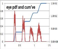
4 Proposal for TDEC for PAM4 signals -2 Conceptual basics Measure the combined O/E and 'scope noise without signal, σ OE Measure histogram through equalized eye to be tested, normalize Equalization is done in the 'scope with a ref. equalizer (eg 5 T/2 tap FFE) A sampling 'scope would need to do the equivalent of: measure the noise on the unequalized pattern, capture the averaged pattern and equalize it, and add back in a noise term which is consistent with the noise frequency spectrum and equalization applied The histogram is a vector representing the vertical probability density function (PDF) through the PAM4 eye Do this for left and right of eye time centre From the vertical PDF through the PAM4 eye, create 3 cumulative probability functions, one around each sub-eye threshold. Add normalized Gaussian noise term σ G to the sub-eye thresholds to create 3 PDFs consisting of a Gaussian PDF centred around each of the sub-eye thresholds Multiply each threshold PDF by the appropriate cum've eye PDF to calculate a proxy for SER for that threshold; sum the results Find smallest size of σ G that makes resultant = target SER = 3.2x10⁻⁴ Root sum square the 'scope noise to σ see note G Find the equivalent σ ideal for an ideal PAM4 signal: σ ideal = OOOOOO 6QQQQ TDEC is the db ratio of σ ideal and (σ G2 +σ OE2 ) ½ see note Note: additional manipulation of σ G is needed to account for noise filtering by the EQ 4

5 Test Method: Two histograms σ G Normalized time through the eye-diagram, Unit Interval P th3 P th2 P ave + OMA/3 Average optical power, P ave OMA P th1 P ave - OMA/3 5
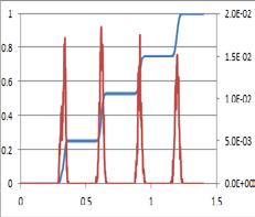
6 P th3 Processing, for each histogram through the eye Threshold pdf Cum've pdf, for each Resultant is a proxy for symbol error ratio (SER) P th2 P th1 Create three cumulative probability functions, one around each threshold Find the smallest value of σ G to make SER = target SER Borrowing from 100GBASE-SR4, the noise, R, that could be added by a receiver is: R = (1-M 1 ).[σ G 2 + σ OE 2 - M 22 ] ½ where M 1 and M 2 account for mode partition noise and modal noise (both are zero for SMF applications), and σ OE is the rms noise of the O/E and scope combination. TDEC is given by: TDEC = 10. log 10 (OOOOOO 6 1 QQ tt RR ) where Q t is the Q function value consistent with the target symbol error ratio equation (1) equation (2) The largest TDEC value, calculated for either left or right histogram, is used 6

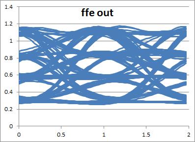
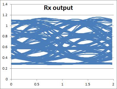
7 Model to emulate eyes and calculate TDEC Dimensionless impulse response based spreadsheet model quasi 'rate equation' laser, with RIN (to produce life-like waveforms) PAM4 data from sequential pairs of bits from a PRBS9 pattern Expanded to 32 samples per bit period Gaussian channel and Rx bandwidths, 5 tap T/2 FFE Output eyes from laser, Rx and FFE Vertical histograms through eye (256 points per time slice per noise instance) 16 noise instances used to build statistics for TDEC calculations 7


")


8 Modeling output: nominal Tx Eyes and eye histograms based on a modelled laser with performance similar to a moderately fast 25G laser at high temperature The NRZ eye for the same VCSEL model is very similar to a typical measured 26G VCSEL eye (RHS) UI between plots Eyes and eye histograms for a moderately fast 25G VCSEL The NRZ eye for the same VCSEL model is similar to typical 26G VCSEL at high temp 8


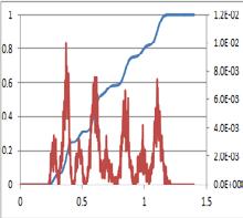
9 TDEC vs time through eye (nominal speed laser) RIN = -146 db/hz 'error probability' cumulative probability plots through eye, centered around each threshold RIN = -142 db/hz P RIN = -138 db/hz RIN = -136 db/hz pdf of noise broadened thresholds TDEC ~1 db at centre of eye TDEC ~2.5 db at +/- 0.1 UI 9


10 Slower laser Modeling output: slow Tx Eyes and eye histograms for a slow 25G VCSEL. 10
 RIN = -142 db/hz (part. err.")


 TDEC ~1-2 db at centre of")
11 TDEC vs time through eye (low speed laser) RIN = -142 db/hz (part. err. prob. on pattern) 'error probability' cumulative probability plots through eye, centered around each threshold RIN = -142 db/hz RIN = -138 db/hz P RIN = -136 db/hz pdf of noise broadened thresholds RIN = -136 db/hz (part. err. prob. on pattern) TDEC ~1-2 db at centre of eye TDEC >5 db at +/- 0.1 UI 11


12 Modeling output: fast Tx Faster laser Eyes and eye histograms for a fast 25G VCSEL. 12
 'error")


13 TDEC vs time through eye (fast laser) 'error probability' cumulative probability plots through eye, centered around each threshold RIN = -142 db/hz RIN = -138 db/hz P pdf of noise broadened thresholds TDEC ~0.5 db at centre of eye TDEC ~1 db at +/- 0.1 UI 13
14 Further work Check the math's, and noise treatment and write out how to treat the noise when capturing the transmitter pattern, and when adding noise to thresholds when calculating TDEC TDEC time sampling points +/- 0.1 UI timing offset is probably too large and may represent an unrealistically large Tx penalty to be reviewed in light of real PAM4 CDR data E.g. a PAM4 CDR with +/-1.25 ps timing errror from centre of eye, and 0.18 ps RJ, would suggest +/-0.05 UI timing offset should be used TDEC validation show good correlation between TDEC and system sensitivity measurements with reference receiver and show good correlation between TDEC and system simulations TDEC calculated by histogram and pattern methods are identical 0 db TDEC achieved at centre of clean eye; Value of σ G for 0dB TDEC consistent with PAM4 modulation penalty and target SER 14


 = 3.")
15 Appendix A: TDEC validation 0 db TDEC at the centre of an ideal eye Max R = OMA inner = 1/3 OMA inner /(2R) =
16 Appendix B: Notes on noise treatment Noise is effectively added at the receiver to calculate TDEC Since the Rx precedes the EQ, the noise density vs frequency matters. Assuming an FFE implementation for simplicity: Typically, the FFE is boosting high frequencies to open the eye high frequency noise is increased by the FFE if the noise term present at each tap is uncorrelated, the relative noise amplitude increases as the RSS of the tap ratios (typically >1) low frequency noise is reduced if the noise terms at the taps are correlated, the relative noise amplitude increases as the sum of the tap ratios (typically < 1) for TDEC calculations, the frequency content of the noise after the EQ is not important, but the amplitude of the noise is Maybe assuming pink noise which is uncorrelated at each FFE tap is a reasonable starting point 16
17 Changes needed to incorporate TDEC into clause 123 work in progress to be presented separately 17
TDEC for PAM4 ('TDECQ') Changes to clause 123, to replace TDP with TDECQ Draft 1. May 3rd 2016 Jonathan King
 Changes to clause 123, to replace TDP with TDECQ Draft 1. May 3rd 2016 Jonathan King") TDEC for PAM4 ('TDECQ') Changes to clause 123, to replace TDP with TDECQ Draft 1 May 3rd 2016 Jonathan King 1 Proposal for TDEC for PAM4 signals -1 Scope based, TDEC variant expanded for all three sub-eyes
TDEC for PAM4 ('TDECQ') Changes to clause 123, to replace TDP with TDECQ Draft 1 May 3rd 2016 Jonathan King 1 Proposal for TDEC for PAM4 signals -1 Scope based, TDEC variant expanded for all three sub-eyes
TDEC for PAM4 ('TDECQ') Changes to clause 123, to replace TDP with TDECQ Draft 1a. May 3 rd 2016 Jonathan King Finisar
 Changes to clause 123, to replace TDP with TDECQ Draft 1a. May 3 rd 2016 Jonathan King Finisar") TDEC for PAM4 ('TDECQ') Changes to clause 123, to replace TDP with TDECQ Draft 1a May 3 rd 2016 Jonathan King Finisar 1 Proposal for TDECQ for PAM4 signals -1 Scope based, TDEC variant expanded for all
TDEC for PAM4 ('TDECQ') Changes to clause 123, to replace TDP with TDECQ Draft 1a May 3 rd 2016 Jonathan King Finisar 1 Proposal for TDECQ for PAM4 signals -1 Scope based, TDEC variant expanded for all
TDECQ update noise treatment and equalizer optimization (revision of king_3bs_02_0217_smf)
") TDECQ update noise treatment and equalizer optimization (revision of king_3bs_02_0217_smf) 21st February 2017 P802.3bs SMF ad hoc Jonathan King, Finisar 1 Preamble TDECQ calculates the db ratio of how
TDECQ update noise treatment and equalizer optimization (revision of king_3bs_02_0217_smf) 21st February 2017 P802.3bs SMF ad hoc Jonathan King, Finisar 1 Preamble TDECQ calculates the db ratio of how
TDECQ changes and consequent spec limits
 TDECQ changes and consequent spec limits 802.3bs SMF ad hoc, 13th June 2017 Jonathan King, Finisar With data from Marco Mazzini, Cisco Marlin Viss, Keysight 1 Intro: Link budget, OMA outer and TDECQ Power
Improved 100GBASE-SR4 transmitter testing
 Improved 100GBASE-SR4 transmitter testing Piers Dawe IEEE P802.3bm, May 2014, Norfolk, VA Supporters Paul Kolesar Mike Dudek Ken Jackson Commscope QLogic Sumitomo 2 Introduction The way of defining transmitter
Additional PAM4 transmitter constraints (comments 52, 54, 57, 59, 27) 802.3cd interim, Pittsburgh, May 2018 Jonathan King, Chris Cole, Finisar
 802.3cd interim, Pittsburgh, May 2018 Jonathan King, Chris Cole, Finisar") Additional PAM4 transmitter constraints (comments 52, 54, 57, 59, 27) 802.3cd interim, Pittsburgh, May 2018 Jonathan King, Chris Cole, Finisar 1 Contents Introduction Transmitter transition time proposal
Additional PAM4 transmitter constraints (comments 52, 54, 57, 59, 27) 802.3cd interim, Pittsburgh, May 2018 Jonathan King, Chris Cole, Finisar 1 Contents Introduction Transmitter transition time proposal
100G SR4 TxVEC Update. John Petrilla: Avago Technologies May 15, 2014
 100G SR4 TxVEC Update John Petrilla: Avago Technologies May 15, 2014 Presentation Summary Presentation Objectives: Review/update proposed replacement for TDP Extracted from petrilla_01_0314_optx.pdf Review
Comment Supporting materials: The Reuse of 10GbE SRS Test for SR4/10, 40G-LR4. Frank Chang Vitesse
 Comment Supporting materials: The Reuse of 10GbE SRS Test for SR4/10, 40G-LR4 Frank Chang Vitesse Review 10GbE 802.3ae testing standards 10GbE optical tests and specifications divided into Transmitter;
10GBASE-S Technical Feasibility
 10GBASE-S Technical Feasibility Picolight Cielo IEEE P802.3ae Los Angeles, October 2001 Interim meeting 1 10GBASE-S Feasibility Supporters Petar Pepeljugoski, IBM Tom Lindsay, Stratos Lightwave Bob Grow,
BERT bathtub, TDP and stressed eye generator
 BERT bathtub, TDP and stressed eye generator From discussions in optics track 17-18 Jan 02 Transcribed by Piers Dawe, Agilent Technologies Tom Lindsay, Stratos Lightwave Raleigh, NC, January 2002 Two problem
TDECQ versus real receiver slope.
 TDECQ versus real receiver slope. Authors: Marco Mazzini Cisco Matt Traverso Cisco Jonathan King Finisar Marlin Viss - Keysight TDECQ versus real receiver slope 1 Background Transmitter and dispersion
SRS test source calibration: measurement bandwidth (comment r03-9) P802.3cd ad hoc, 27 th June 2018 Jonathan King, Finisar
 P802.3cd ad hoc, 27 th June 2018 Jonathan King, Finisar") SRS test source calibration: measurement bandwidth (comment r03-9) P802.3cd ad hoc, 27 th June 2018 Jonathan King, Finisar 1 SRS test source calibration measurement bandwidth in D3.2 Refers back to 121.8.5
SRS test source calibration: measurement bandwidth (comment r03-9) P802.3cd ad hoc, 27 th June 2018 Jonathan King, Finisar 1 SRS test source calibration measurement bandwidth in D3.2 Refers back to 121.8.5
MPI statistical model and results. 7 th January 2016 Jonathan King
 MPI statistical model and results 7 th January 2016 Jonathan King 1 Aims 1) Show impact of 3 db mid-span loss on MPI penalty P MPI 2) Look at MPI penalties for the 3 link scenarios shown in kolesar_01_0715
400G CWDM8 10 km Optical Interface Technical Specifications Revision 1.0
 400G CWDM8 10 km Optical Interface Technical Specifications Revision 1.0 Contact: cwdm8-msa.org CWDM8 10 km Technical Specifications, Revision 1.0 1 Table of Contents 1. General...5 1.1. Scope...5 1.2.
100G CWDM4 MSA Technical Specifications 2km Optical Specifications
 100G CWDM4 MSA Technical Specifications 2km Specifications Participants Editor David Lewis, LUMENTUM Comment Resolution Administrator Chris Cole, Finisar The following companies were members of the CWDM4
Experimental results on single wavelength 100Gbps PAM4 modulation. Matt Traverso, Cisco Marco Mazzini, Cisco Atul Gupta, Macom Tom Palkert, Macom
 Experimental results on single wavelength 100Gbps PAM4 modulation Matt Traverso, Cisco Marco Mazzini, Cisco Atul Gupta, Macom Tom Palkert, Macom 1 Past Presentations Selection of presentations at ieee
Dynamic Behavior of Mode Partition Noise in MMF. Petar Pepeljugoski IBM Research
 Dynamic Behavior of Mode Partition Noise in MMF Petar Pepeljugoski IBM Research 1 Motivation and Issues Inconsistent treatment of mode partition noise (MPN) and relative intensity noise (RIN) in spreadsheet
Jitter in Digital Communication Systems, Part 1
 Application Note: HFAN-4.0.3 Rev.; 04/08 Jitter in Digital Communication Systems, Part [Some parts of this application note first appeared in Electronic Engineering Times on August 27, 200, Issue 8.] AVAILABLE
Clarifying Issues Related to Spreadsheet Model using Full Link Simulation for 25G on MMF
 Clarifying Issues Related to Spreadsheet Model using Full Link Simulation for 25G on MMF Kasyapa Balemarthy Robert Lingle Jr. September 26-28, 2012 IEEE 802.3bm Task Force Spreadsheet Spreadsheet has served
Results of a Practical Measurement System for the TP3 Comprehensive Stressed Receiver Sensitivity and Overload Test
 Results of a Practical Measurement System for the TP3 Comprehensive Stressed Receiver Sensitivity and Overload Test Finisar September 9, 2005 Page: 1 Introduction IEEE 802.3aq D2.2 68.6.9 Comprehensive
400G-FR4 Technical Specification
 400G-FR4 Technical Specification 100G Lambda MSA Group Rev 2.0 September 18, 2018 Chair Mark Nowell, Cisco Systems Co-Chair - Jeffery J. Maki, Juniper Networks Marketing Chair - Rang-Chen (Ryan) Yu Editor
TDEC, OMA and TDP Evaluation for 25G EPON
 TDEC, OMA and TDP Evaluation for 25G EPON Vincent Houtsma & Dora van Veen Optical Access Research, Nokia Bell Labs, Murray Hill, NJ IEEE P802.3ca 100G-EPON Task Force Meeting, Orlando, FL, November 2017
06-496r3 SAS-2 Electrical Specification Proposal. Kevin Witt SAS-2 Phy Working Group 1/16/07
 06-496r3 SAS-2 Electrical Specification Proposal Kevin Witt SAS-2 Phy Working Group 1/16/07 Overview Motivation Multiple SAS-2 Test Chips Have Been Built and Tested, SAS-2 Product Designs have Started
Proposal for 400GE Optical PMDs for SMF Objectives based on 4 x 100G DMT David Lewis, Sacha Corbeil, Beck Mason
 Proposal for 400GE Optical PMDs for SMF Objectives based on 4 x 100G DMT David Lewis, Sacha Corbeil, Beck Mason Summary - 10km objectives (400GBASE-LR4) covered in takahara_3bs_01_1114 - This presentation
MMF Channel Characteristics
 MMF Channel Characteristics J. Ewen, E. Borisch JDS Uniphase P. Pepeljugoski, A. Risteski IBM 1 Motivation / Outline Fiber impulse response Critical importance of launch conditions, connectors, etc. Variability
Signal metrics for 10GBASE-LRM. Piers Dawe Agilent. John Ewen JDSU. Abhijit Shanbhag Scintera
 Signal metrics for 10GBASE-LRM Piers Dawe Agilent. John Ewen JDSU. Abhijit Shanbhag Scintera Statement of problem Measure signal strength and quality Need: from data terminal equipment (DTE) at TP2 Need:
Wavelength (nm) (m) ( o C) SPM-2100AWG 10.3 SR / SW 300 / 82 / 33* 850 VCSEL SFP+ with DMI -40 to 85 Yes
 (m) ( o C) SPM-2100AWG 10.3 SR / SW 300 / 82 / 33* 850 VCSEL SFP+ with DMI -40 to 85 Yes") / SPM-2100BWG / SPM-2100AWG (RoHS Compliant) 3.3V / 850 nm / 10.3 Gb/s Digital Diagnostic SFP+ LC Multi-Mode TRANSCEIVER ********************************************************************************************************************************************************************
/ SPM-2100BWG / SPM-2100AWG (RoHS Compliant) 3.3V / 850 nm / 10.3 Gb/s Digital Diagnostic SFP+ LC Multi-Mode TRANSCEIVER ********************************************************************************************************************************************************************
Dynamic Behavior of Mode Partition Noise in MMF. Petar Pepeljugoski IBM Research
 Dynamic Behavior of Mode Partition Noise in MMF Petar Pepeljugoski IBM Research 1 Motivation and Issues Inconsistent treatment of mode partition noise (MPN) and relative intensity noise (RIN) in spreadsheet
Beta and Epsilon Point Update. Adam Healey Mark Marlett August 8, 2007
 Beta and Epsilon Point Update Adam Healey Mark Marlett August 8, 2007 Contributors and Supporters Dean Wallace, QLogic Pravin Patel, IBM Eric Kvamme, LSI Tae-Kwang Jeon, LSI Bill Fulmer, LSI Max Olsen,
Keysight Technologies Greg LeCheminant / Robert Sleigh
 Keysight Technologies 2018.01.31 Greg LeCheminant / Robert Sleigh Introduction Why use Pulse Amplitude Modulation 4-Level (PAM4)? Review Standards using PAM4 Output (Transmitter) Characterization Key Optical
Experimental Demonstration of 56Gbps NRZ for 400GbE 2km and 10km PMD Using 100GbE Tx & Rx with Rx EQ
 Experimental Demonstration of 56Gbps NRZ for 400GbE 2km and 10km PMD Using 100GbE Tx & Rx with Rx EQ Yangjing Wen, Fei Zhu, and Yusheng Bai Huawei Technologies, US R&D Center Santa Clara, CA 95050 IEEE802.3bs
10Gb/s PMD Using PAM-5 Modulation. Oscar Agazzi Broadcom Corp Alton Parkway Irvine, CA 92618
 10Gb/s PMD Using PAM-5 Modulation Oscar Agazzi Broadcom Corp. 16215 Alton Parkway Irvine, CA 92618 1 Goals Achieve distance objective of 300m over existing MMF Operate with single channel optoelectronic
Modal Noise and Implications for the CSRS Test
 Optical Navigation Division Modal Noise and Implications for the CSRS Test David Cunningham, Piers Dawe, John Ewen, Christine M. Krause, Petar Pepeljugoski, Abhijit Shanbhag, Nick Weiner, Avago Technologies
40 AND 100 GIGABIT ETHERNET CONSORTIUM
 40 AND 100 GIGABIT ETHERNET CONSORTIUM Clause 93 100GBASE-KR4 PMD Test Suite Version 1.0 Technical Document Last Updated: October 2, 2014 40 and 100 Gigabit Ethernet Consortium 121 Technology Drive, Suite
QFX-SFP-10GE-SR (10G BASE-SR SFP+) Datasheet
 Datasheet") QFX-SFP-10GE-SR (10G BASE-SR SFP+) Datasheet Features Optical interface compliant to IEEE 802.3ae 10GBASE-LR Electrical interface compliant to SFF-8431 850nm VCSEL transmitter, PIN photo-detector Maximum
QFX-SFP-10GE-SR (10G BASE-SR SFP+) Datasheet Features Optical interface compliant to IEEE 802.3ae 10GBASE-LR Electrical interface compliant to SFF-8431 850nm VCSEL transmitter, PIN photo-detector Maximum
10GBASE-T Transmitter SNDR Definition (System ID Approach) IEEE P802.3an Task Force Santa Clara, Feb 2005 Albert Vareljian, Hiroshi Takatori KeyEye
 IEEE P802.3an Task Force Santa Clara, Feb 2005 Albert Vareljian, Hiroshi Takatori KeyEye") 10GBASE-T Transmitter SNDR Definition (System ID Approach) IEEE P802.3an Task Force Santa Clara, Feb 2005 Albert Vareljian, Hiroshi Takatori KeyEye 1 OUTLINE Transmitter Performance Evaluation Block Diagram
10GBASE-T Transmitter SNDR Definition (System ID Approach) IEEE P802.3an Task Force Santa Clara, Feb 2005 Albert Vareljian, Hiroshi Takatori KeyEye 1 OUTLINE Transmitter Performance Evaluation Block Diagram
Characterization and Compliance Testing for 400G/PAM4 Designs. Project Manager / Keysight Technologies
 Characterization and Compliance Testing for 400G/PAM4 Designs Project Manager / Keysight Technologies Jacky Yu & Gary Hsiao 2018.06.11 Taipei State of the Standards (Jacky Yu) Tx test updates and learnings
Modal noise in 100GBASE-SR4. Piers Dawe Mellanox Technologies. IEEE P802.3bm, October 2013 Modal noise in 100GBASE-SR4 1
 Modal noise in 100GBASE-SR4 Piers Dawe Mellanox Technologies IEEE P802.3bm, October 2013 Modal noise in 100GBASE-SR4 1 Introduction This presentation investigates the consequences of allowing a reduced
SMF PMD Modulation Observations. 400 Gb/s Ethernet Task Force SMF Ad Hoc Conference Call 24 February 2015 Chris Cole
 SMF PMD Modulation Observations 400 Gb/s Ethernet Task Force SMF Ad Hoc Conference Call 24 February 2015 Chris Cole Shannon-Hartley Theorem C = B log 2 (1 + S/N) C Channel capacity B Bandwidth S Signal
10GBASE-S Technical Feasibility RECAP
 10GBASE-S Technical Feasibility RECAP Picolight Cielo Stratos Lightwave Corning CDT-Optical Lucent IBM IEEE P802.3ae Austin, TX November 2001 Plenary meeting 1 10GBASE-S Feasibility supporters Bob Grow,
06-011r0 Towards a SAS-2 Physical Layer Specification. Kevin Witt 11/30/2005
 06-011r0 Towards a SAS-2 Physical Layer Specification Kevin Witt 11/30/2005 Physical Layer Working Group Goal Draft a Specification which will: 1. Meet the System Designers application requirements, 2.
Jitter Measurements using Phase Noise Techniques
 Jitter Measurements using Phase Noise Techniques Agenda Jitter Review Time-Domain and Frequency-Domain Jitter Measurements Phase Noise Concept and Measurement Techniques Deriving Random and Deterministic
IEEE 802.3aq Task Force Dynamic Channel Model Ad Hoc Task 2 - Time variation & modal noise 10/13/2004 con-call
 IEEE 802.3aq Task Force Dynamic Channel Model Ad Hoc Task 2 - Time variation & modal noise 10/13/2004 con-call Time variance in MMF links Further test results Rob Coenen Overview Based on the formulation
IEEE P802.3bm D Gb/s & 100 Gb/s Fiber Optic TF 1st Sponsor recirculation ballot comments
 Cl 00 SC 0 P L Anslow, Peter # r01-3 Now that IEEE Std 802.3bj-2014 has been approved by the standards board, "802.3bj- 201x" can be changed to "802.3bj-2014" Change "802.3bj-201x" to "802.3bj-2014" throughout
Electronic Dispersion Compensation of 40-Gb/s Multimode Fiber Links Using IIR Equalization
 Electronic Dispersion Compensation of 4-Gb/s Multimode Fiber Links Using IIR Equalization George Ng & Anthony Chan Carusone Dept. of Electrical & Computer Engineering University of Toronto Canada Transmitting
Product Specification 100GBASE-SR10 100m CXP Optical Transceiver Module FTLD10CE1C APPLICATIONS
 Product Specification 100GBASE-SR10 100m CXP Optical Transceiver Module FTLD10CE1C PRODUCT FEATURES 12-channel full-duplex transceiver module Hot Pluggable CXP form factor Maximum link length of 100m on
PROLABS XENPAK-10GB-SR-C
 PROLABS XENPAK-10GB-SR-C 10GBASE-SR XENPAK 850nm Transceiver XENPAK-10GB-SR-C Overview PROLABS s XENPAK-10GB-SR-C 10 GBd XENPAK optical transceivers are designed for Storage, IP network and LAN, it is
SFP-10G-SR-Arista-A SFP+, 10GBASE-SR 10G Ethernet Module 850mn, 300m, MMF, LC RoHS6. Approved Optics, Inc.
 SFP-10G-SR-Arista-A 10Gbase SFP+ Transceiver Features Compliant to SFP+ Electrical MSA SFF-8431 Compliant to SFP+ Mechanical MSA SFF-8432 Multi-rate compliance for Ethernet and Fiber Channel Transmission
SFP-10G-M 10G Ethernet SFP+ Transceiver
 SFP+, LC Connector, 850nm VCSEL with PIN Receiver, Multi Mode, 300M Features Applications High-speed storage area networks Computer cluster cross-connect Custom high-speed data pipes 10GE Storage, 8G Fiber
QSFP SFP-QSFP-40G-LR4
 Features Compliant with 40G Ethernet IEEE802.3ba and 40GBASE-LR4 Standard QSFP+ MSA compliant Compliant with QDR/DDR Infiniband data rates Up to 11.2Gb/s data rate per wavelength 4 CWDM lanes MUX/DEMUX
Understanding Apparent Increasing Random Jitter with Increasing PRBS Test Pattern Lengths
 JANUARY 28-31, 2013 SANTA CLARA CONVENTION CENTER Understanding Apparent Increasing Random Jitter with Increasing PRBS Test Pattern Lengths 9-WP6 Dr. Martin Miller The Trend and the Concern The demand
Jitter Analysis Techniques Using an Agilent Infiniium Oscilloscope
 Jitter Analysis Techniques Using an Agilent Infiniium Oscilloscope Product Note Table of Contents Introduction........................ 1 Jitter Fundamentals................. 1 Jitter Measurement Techniques......
Why new method? (stressed eye calibration)
") Why new method? (stressed eye calibration) Problem Random noises (jitter, RIN, etc.), long pattern DDJ, and the Golden PLL cloud the ability to calibrate deterministic terms Knob setting are interdependent
Why new method? (stressed eye calibration) Problem Random noises (jitter, RIN, etc.), long pattern DDJ, and the Golden PLL cloud the ability to calibrate deterministic terms Knob setting are interdependent
T Q S Q 7 4 H 9 J C A
 Specification Quad Small Form-factor Pluggable Optical Transceiver Module 100GBASE-SR4 Ordering Information T Q S Q 7 4 H 9 J C A Model Name Voltage Category Device type Interface Temperature Distance
TDECQ results is function of the 4th-order B-T filter roll-off stop frequency. We are proposing to mandate the minimum roll-off stop frequency.
 TDECQ results is function of the 4th-order B-T filter roll-off stop frequency. We are proposing to mandate the minimum roll-off stop frequency. Pavel Zivny, Kan Tan zivny_3cd_01b_0118 2018/01 Geneva Supporters
Application Note AN-23 Copyright September, 2009
 Removing Jitter From Picosecond Pulse Measurements James R. Andrews, Ph.D, IEEE Fellow PSPL Founder and former President (retired) INTRODUCTION: Uncertainty is always present in every measurement. Uncertainties
IEEE 802.3ba 40Gb/s and 100Gb/s Ethernet Task Force 22th Sep 2009
 Draft Amendment to IEEE Std 0.-0 IEEE Draft P0.ba/D. IEEE 0.ba 0Gb/s and 00Gb/s Ethernet Task Force th Sep 0.. Stressed receiver sensitivity Stressed receiver sensitivity shall be within the limits given
ECEN689: Special Topics in Optical Interconnects Circuits and Systems Spring 2016
 ECEN689: Special Topics in Optical Interconnects Circuits and Systems Spring 016 Lecture 7: Transmitter Analysis Sam Palermo Analog & Mixed-Signal Center Texas A&M University Optical Modulation Techniques
Transmit Waveform Calibration for Receiver Testing. Kevin Witt & Mahbubul Bari Jan 15, r1
 Transmit Waveform Calibration for Receiver Testing Kevin Witt & Mahbubul Bari Jan 15, 2008 07-492r1 1 Goal Evaluate ISI Calibration of the Delivered Signal for the Stressed Receiver Sensitivity Test (07-486
QSFP SV-QSFP-40G-LR4L
 Features 4 CWDM lanes MUX/DEMUX design Up to 11.2Gb/s data rate per wavelength QSFP+ MSA compliant IEEE 802.3ba Electrical Interface Up to 2km transmission on single mode fiber (SMF) Operating case temperature:
P802.3cd Clause 138 hazard level recommendations. P802.3cd Interim meeting, May 2017 Richard Johnson and Jonathan King, Finisar
 P802.3cd Clause 138 hazard level recommendations P802.3cd Interim meeting, May 2017 Richard Johnson and Jonathan King, Finisar 1 Laser safety assessment 50GBASE-SR, 100GBASE-SR2, 200GBASE-SR4 Max average
Noise Measurements Using a Teledyne LeCroy Oscilloscope
 Noise Measurements Using a Teledyne LeCroy Oscilloscope TECHNICAL BRIEF January 9, 2013 Summary Random noise arises from every electronic component comprising your circuits. The analysis of random electrical
850 nm Serial LAN PHY 1310 nm Serial LAN PHY 1550 nm Serial LAN PHY 1310 nm WWDM LAN PHY
 ONIDS 00 Review of the 0Gigabit Ethernet Link Model White Paper By David Cunningham & Piers Dawe Abstract The theoretical model used by 0Gigabit Ethernet IEEE 80.3ae to develop the optical physical layer
10GBd SFP+ Short Wavelength (850nm) Transceiver
 Transceiver") Preliminary DATA SHEET CFORTH-SFP+-10G-SR 10GBd SFP+ Short Wavelength (850nm) Transceiver CFORTH-SFP+-10G-SR Overview CFORTH-SFP+-10G-SR SFP optical transceivers are based on 10G Ethernet IEEE 802.3ae
Preliminary DATA SHEET CFORTH-SFP+-10G-SR 10GBd SFP+ Short Wavelength (850nm) Transceiver CFORTH-SFP+-10G-SR Overview CFORTH-SFP+-10G-SR SFP optical transceivers are based on 10G Ethernet IEEE 802.3ae
Multilane MM Optics: Considerations for 802.3ba. John Petrilla Avago Technologies March 2008
 Multilane MM Optics: Considerations for 802.3ba John Petrilla Avago Technologies March 2008 Acknowledgements & References pepeljugoski_01_0108 Orlando, FL, March 2008 Multilane MM Optics: Considerations
This 1310 nm DFB 10Gigabit SFP+ transceiver is designed to transmit and receive optical data over single mode optical fiber for link length 10km.
 10G-SFPP-LR-A 10Gbase SFP+ Transceiver Features 10Gb/s serial optical interface compliant to 802.3ae 10GBASE LR Electrical interface compliant to SFF-8431 specifications for enhanced 8.5 and 10 Gigabit
Product Specification RoHS-6 Compliant 10Gb/s 850nm Multimode Datacom XFP Optical Transceiver
 Product Specification RoHS-6 Compliant 10Gb/s 850nm Multimode Datacom XFP Optical Transceiver PRODUCT FEATURES Hot-pluggable XFP footprint Supports 9.95Gb/s to 10.5Gb/s bit rates Power dissipation
Channel operating margin for PAM4 CDAUI-8 chip-to-chip interfaces
 Channel operating margin for PAM4 CDAUI-8 chip-to-chip interfaces Adam Healey Avago Technologies IEEE P802.3bs 400 GbE Task Force March 2015 Introduction Channel Operating Margin (COM) is a figure of merit
Alan Tipper 24 FEB 2015
 100Gb/s/Lambda 2km PAM4 with KP4 FEC: System Modelling & The Big Ticket Items Alan Tipper 24 FEB 2015 1 Big Ticket Items lewis_3bs_01a_0115 ( 4 x 100G PAM4 Proposal) Allocation for MPI penalty 1.0 db No
Improvements to Modal Noise Penalty Calculations
 Improvements to Modal Noise Penalty Calculations Petar Pepeljugoski, Daniel Kuchta and Aleksandar Risteski IBM T.J. Watson Research Center Yorktown Heights, NY 1598 Outline Modal Noise (MN) penalty calculation
XFP 10G MM SR. 10Gbps XFP Optical Transceiver, 300m Reach
 XFP 10G MM SR 10Gbps XFP Optical Transceiver, 300m Reach Features Supports 9.95Gbps to 10.5Gbps bit rates Maximum link length of 300m (50um,MMF,2000MHz.Km) 850nm VCSEL laser and PIN receiver Low power
Does PAM-4 or NRZ Require an Intra-Baud Clipping Penalty?
 Does PAM-4 or NRZ Require an Intra-Baud Clipping Penalty? Will Bliss Office of the CTO Broadcom Corp. IEEE 802.3bs task force San Antonio, TX Nov. 3, 2014 1 SUPPORTERS Vipul Bhatt Beck Mason Brian Welch
Gb/s, DML, PAM-4 10 km Transmission: FFE Tap Number Perspective
 53.125 Gb/s, DML, PAM-4 10 km Transmission: FFE Tap Number Perspective Prashant P Baveja, Mingshan Li, Pablo Li, Huanlin Zhang, Jun Zheng Applied Optoelectronics Inc. (AOI) October 31, 2017 Supporters
VCSEL Friendly 1550nm Specifications
 VCSEL Friendly 1550nm Specifications Jim Tatum Manager Honeywell 830 E. Arapaho Richardson, TX Jim.Tatum@Honeywell.com (972) 470-4572 Interoperability with 1310nm/10km specification The receivers will
Real Time Jitter Analysis
 Real Time Jitter Analysis Agenda ı Background on jitter measurements Definition Measurement types: parametric, graphical ı Jitter noise floor ı Statistical analysis of jitter Jitter structure Jitter PDF
Jitter in Digital Communication Systems, Part 2
 Application Note: HFAN-4.0.4 Rev.; 04/08 Jitter in Digital Communication Systems, Part AVAILABLE Jitter in Digital Communication Systems, Part Introduction A previous application note on jitter, HFAN-4.0.3
Product Specification 40GE SWDM4 QSFP+ Optical Transceiver Module FTL4S1QE1C
 1 Product Specification 40GE SWDM4 QSFP+ Optical Transceiver Module FTL4S1QE1C 9BPRODUCT FEATURES Hot-pluggable QSFP+ form factor 240m operation over duplex OM3 MMF (350m over OM4, 440m over OM5) Supports
QSFP SV-QSFP-40G-PLR4L
 Features 4 Parallel lanes design Up to 11.2Gb/s data rate per channel Aggregate Bandwidth of up to 44.0G QSFP+ MSA compliant Up to 1.4km transmission on single mode fiber (SMF) Maximum power consumption
IEEE P802.3bs D Gb/s & 400 Gb/s Ethernet 3rd Sponsor recirculation ballot comments
 Cl 120D SC 120D.4 P 360 L 4 # i-73 Cl 121 SC 121.8.5.3 P 228 L 9 # i-140 Dudek, Michael Cavium Simulations presented in the 802.3cd task force have shown that the value of COM for 20dB channels varies
SPM-6100WG / SPM-6100BWG / SPM-6100AWG
 / SPM-6100BWG / SPM-6100AWG (RoHS Compliant) 16G FC / 850 nm Digital Diagnostic LC Multi-Mode SFP+ TRANSCEIVER ********************************************************************************************************************************************************************
Backchannel Modeling and Simulation Using Recent Enhancements to the IBIS Standard
 Backchannel Modeling and Simulation Using Recent Enhancements to the IBIS Standard By Ken Willis, Product Engineering Architect; Ambrish Varma, Senior Principal Software Engineer; Dr. Kumar Keshavan, Senior
Optical Digital Transmission Systems. Xavier Fernando ADROIT Lab Ryerson University
 Optical Digital Transmission Systems Xavier Fernando ADROIT Lab Ryerson University Overview In this section we cover point-to-point digital transmission link design issues (Ch8): Link power budget calculations
Senior Project Manager / Keysight Joe Lin 林昭彥
 Senior Project Manager / Keysight 2017.04.17 Joe Lin 林昭彥 How do you build a 400G optical link? Multimode fiber or single-mode fiber? IEEE 802.3bs 400G will use both multimode fiber for 100 meter spans
SFP-10G-SR Specifications, R01. SFP-10G-SR-OEM 10GBd SFP+ Short Wavelength (850nm) Transceiver
 Transceiver") SFP-10G-SR-OEM 10GBd SFP+ Short Wavelength (850nm) Transceiver Up to 10.5 GBd bi-directional data links Compliant with IEEE 802.3ae 10GBASE-SR/SW Compliant with SFF8431 Hot-pluggable SFP+ footprint 850nm
SFP-10G-SR-OEM 10GBd SFP+ Short Wavelength (850nm) Transceiver Up to 10.5 GBd bi-directional data links Compliant with IEEE 802.3ae 10GBASE-SR/SW Compliant with SFF8431 Hot-pluggable SFP+ footprint 850nm
IEEE P802.3bs D Gb/s & 400 Gb/s Ethernet 4th Sponsor recirculation ballot comments
 Cl 120E SC 120E.3.1 P 369 L 19 # i-119 Cl 120D SC 120D.3.1.1 P 353 L 24 # r01-36 The host is allowed to output a signal with large peak-to-peak amplitude but very small EH - in other words, a very bad
T A S A 1 N H 1 P 1 1
 Specification Small Form Factor Pluggable Duplex LC Receptacle SFP+ Optical Transceivers 10 Gigabit Ethernet 10GBASE-SR Ordering Information T A S A 1 N H 1 P 1 1 Voltage / Temperature 1 : 3.3V / 0 ~ +70
Parameter Fiber Type Modal 850nm (MHz-km) Distance Range (m) 62.5/125um MMF /125um MMF
 Distance Range (m) 62.5/125um MMF /125um MMF") SFP-10G-SR-GT SFP-10G-SR-GT is programmed to be fully compatible and functional with all intended Cisco switching devices. This SFP module is based on the 10G Ethernet IEEE 802.3ae standard and is designed
SFP-10G-SR-GT SFP-10G-SR-GT is programmed to be fully compatible and functional with all intended Cisco switching devices. This SFP module is based on the 10G Ethernet IEEE 802.3ae standard and is designed
Comparison of Time Domain and Statistical IBIS-AMI Analyses
 Comparison of Time Domain and Statistical IBIS-AMI Analyses Mike LaBonte SiSoft Asian IBIS Summit 2017 Shanghai, PRC November 13, 2017 9 Combinations of TX and RX Model Types AMI file has: GetWave_Exists
PROLABS J9150A-C 10GBd SFP+ Short Wavelength (850nm) Transceiver
 Transceiver") PROLABS J9150A-C 10GBd SFP+ Short Wavelength (850nm) Transceiver J9150A-C Overview PROLABS s J9150A-C SFP optical transceivers are based on 10G Ethernet IEEE 802.3ae standard and SFF 8431 standard, and
PROLABS J9150A-C 10GBd SFP+ Short Wavelength (850nm) Transceiver J9150A-C Overview PROLABS s J9150A-C SFP optical transceivers are based on 10G Ethernet IEEE 802.3ae standard and SFF 8431 standard, and
Comparison of Time Domain and Statistical IBIS-AMI Analyses Mike LaBonte SiSoft
 Comparison of Time Domain and Statistical IBIS-AMI Analyses Mike LaBonte SiSoft Asian IBIS Summit 2017 Taipei, ROC November 15, 2017 9 Combinations of TX and RX Model Types AMI file has: GetWave_Exists
BACKPLANE ETHERNET CONSORTIUM
 BACKPLANE ETHERNET CONSORTIUM Clause 72 10GBASE-KR PMD Test Suite Version 1.1 Technical Document Last Updated: June 10, 2011 9:28 AM Backplane Ethernet Consortium 121 Technology Drive, Suite 2 Durham,
Product Specification 100GBASE-SR10 100m CXP Optical Transceiver Module FTLD10CE3C
 Product Specification 100GBASE-SR10 100m CXP Optical Transceiver Module FTLD10CE3C PRODUCT FEATURES 12-channel full-duplex transceiver module Hot Pluggable CXP form factor Multirate capability: 1Gb/s to
Partial Response Signaling for Backplane Applications
 Partial Response Signaling for Backplane Applications IEEE 82.3ap Task Force September 24 Michael Altmann Fulvio Spagna IEEE 82.3ap Task Force - 24-Sep-4 Agenda Introduction Line coding alternatives for
PROLABS GP-10GSFP-1S-C 10GBd SFP+ Short Wavelength (850nm) Transceiver
 Transceiver") PROLABS GP-10GSFP-1S-C 10GBd SFP+ Short Wavelength (850nm) Transceiver GP-10GSFP-1S-C Overview PROLABS s GP-10GSFP-1S-C SFP optical transceivers are based on 10G Ethernet IEEE 802.3ae standard and SFF
PROLABS GP-10GSFP-1S-C 10GBd SFP+ Short Wavelength (850nm) Transceiver GP-10GSFP-1S-C Overview PROLABS s GP-10GSFP-1S-C SFP optical transceivers are based on 10G Ethernet IEEE 802.3ae standard and SFF
Low frequency jitter tolerance Comments 109, 133, 140. Piers Dawe IPtronics. Charles Moore Avago Technologies
 Low frequency jitter tolerance Comments 109, 133, 140 Piers Dawe IPtronics. Charles Moore Avago Technologies Supporters Adee Ran Mike Dudek Mike Li Intel QLogic Altera P802.3bj Jan 2012 Low frequency jitter
Product Specification. RoHS-6 Compliant 10Gb/s 10km Single Mode Datacom SFP+ Transceiver FTLX1475D3BNV
 Product Specification RoHS-6 Compliant 10Gb/s 10km Single Mode Datacom SFP+ Transceiver FTLX1475D3BNV PRODUCT FEATURES Hot-pluggable SFP+ footprint Supports rate selectable 1.25Gb/s and 9.95 to 10.5Gb/s
10Gb/s SFP+ Optical Transceiver Module 10GBASE-SR/SW
 10Gb/s SFP+ Optical Transceiver Module 10GBASE-SR/SW Features 10Gb/s serial optical interface compliant to 802.3ae 10GBASE SR Electrical interface compliant to SFF 8431 specifications for enhanced 8.5
56+ Gb/s Serial Transmission using Duobinary Signaling
 56+ Gb/s Serial Transmission using Duobinary Signaling Jan De Geest Senior Staff R&D Signal Integrity Engineer, FCI Timothy De Keulenaer Doctoral Researcher, Ghent University, INTEC-IMEC Introduction Motivation
Product Specification
 Product Specification Extended Temperature 10Gb/s 850nm SFP+ Datacom Transceiver FTLX8574D3BNL PRODUCT FEATURES Hot-pluggable SFP+ footprint Supports 9.95 to 10.5 Gb/s bit rates* Power dissipation < 1W
ECEN 720 High-Speed Links: Circuits and Systems
 1 ECEN 720 High-Speed Links: Circuits and Systems Lab4 Receiver Circuits Objective To learn fundamentals of receiver circuits. Introduction Receivers are used to recover the data stream transmitted by