INVERTER. Model FR-F800. Enhanced Next-Generation Energy-Saving Inverter F800 F800
|
|
|
- Frank Stokes
- 5 years ago
- Views:
Transcription

1 INVERTER Model FR-F800 Enhanced Next-Generation Energy-Saving Inverter F800 F800

2 1 ENERGY SAVING Energy Saving with Inverters The consumed power of a variable-torque load, such as fans, pumps, and blowers, is proportional to the cube of its rotation speed. Adjusting the air volume by the inverter rotation speed control can lead to energy savings. [Example of blower operation characteristic] 100 Damper control Optimum excitation control Optimum excitation control continuously adjusts the excitation current to an optimum level to provide the highest motor efficiency. With a small load torque, a substantial energy saving can be achieved. For example, at 4% motor load torque for a general-purpose motor, the motor efficiency under Optimum excitation control is about 30% higher than the motor efficiency under V/F control General-purpose motor (SF-PR) driven by inverter 20 0 Motor efficiency [%] Consumed power (%)*1 120 Utilizing the motor capability to the full *1: Rated motor output is 100% Air volume (%) V/F control [Compared to our conventional product] Optimum excitation control More energy saving Motor load factor [%] 100 [Compared to our conventional product] (When the inverter running frequency is 60 Hz and the SF-PR 4P motor (15 kw) is used) Improving starting torque and saving energy at the same time Advanced optimum excitation control Advanced optimum excitation control, which has been newly developed, provides a large starting torque while maintaining the motor efficiency under the conventional Optimum excitation control. Without the need of troublesome adjustment of parameters (acceleration/deceleration time, torque boost, etc.), acceleration is done in a short time. Also, energy saving operation with the utmost improved motor efficiency is performed during constant-speed operation. Supporting operations of various motors Offline auto tuning The offline auto tuning function to measure circuit constants of the motor enables optimal operation of motors even when motor constants vary, when a motor of other manufacturers is used, or when the wiring distance is long. As well as Mitsubishi general-purpose motors, Mitsubishi PM motors (MM-EFS, MM-THE4), sensorless operation can be performed for other manufacturers' general-purpose motors*2 and other manufacturers' permanent magnet (PM) motors*2. The tuning function enables the Advanced optimum excitation control of other manufacturers' general-purpose motors*2, which increases the use in the energy saving applications. 1 *2: Depending on the motor characteristics, tuning may not be available. Mitsubishi general-purpose (induction) motor SF-HR Mitsubishi general-purpose (induction) motor SF-PR General-purpose motor by other manufacturers PMmotor motorby by PM othermanufacturers manufacturers other Mitsubishi IPM motor MM-EFS
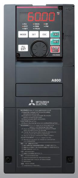
3 PU EXT NET MON PRM P.RUN IM PM FWD REV RESET Inverter Optimum for Fan and Pump Applications Energy Saving with High-Efficiency Motor In the international context of global warming prevention, many countries in the world have started to introduce laws and regulations to mandate manufacturing and sales of high-efficiency motors. With the use of high-efficiency motors, further energy saving is achieved. [IE code] As an international standard of the efficiency, IEC (energy-efficiency classes for singlespeed, three-phase, cage-induction motors) was formulated in October The efficiency is classified into four classes from IE1 to IE4. The larger number means the higher efficiency. High Efficiency Low Efficiency class IEC IE4 (super premium efficiency)* 3 IE3 (premium efficiency) IE2 (high efficiency) IE1 (standard efficiency) Below the class Mitsubishi motor efficiency General-purpose motor IPM motor Superline premium series (SF-PR) Superline eco series (SF-HR) Superline series (SF-JR) Premium high-efficiency IPM (MM-EFS/MM-THE4) *3: The details of IE4 are specified in IEC Further energy saving with the premium high-efficiency IPM motor MM-EFS / MM-THE4 The IPM motor, with permanent magnets embedded in the rotor, achieves even higher efficiency as compared to the general-purpose motor (SF-PR/SF-THE3). The IM driving setting can be switched to IPM driving setting by only one setting. ("12" (MM-EFS/MM-THE4) in the parameter [IPM]). Do not drive an IPM motor in the induction motor control settings. Why is an IPM motor more efficient? No current flows to the rotor (secondary side), and no secondary copper loss is generated. General-purpose motor [Comparison of motor losses] * Example of 22 kw motors Iron loss Magnetic flux is generated with permanent Primary Premium high-efficiency magnets, and less motor current is required. 100% copper loss IPM motor (stator side) Embedded magnets provide reluctance torque* 4, Secondary Iron loss copper loss and the reluctance torque can be applied. (rotor side) Primary copper loss 40% *4: Reluctance torque occurs due to magnetic imbalance on the rotor. Others Others SF-JR MM-EFS Total efficiency (%) [Comparison of efficiency] MM-EFS/MM-THE4 SF-JR/SF-TH Motor capacity (kw) SF-PR/SF-THE [Compared to our conventional product] Excellent compatibility with the high-performance energy-saving motor SF-PR Motor constants are stored in the inverter. Energy-saving operation can be started just by setting parameters. The SF-PR motor conforms to the Japanese domestic Top Runner Standard (IE3 equivalent). Its energy-saving operation contributes reduction in the electricity charges, which in turn lowers the running cost. Efficiency [%] 4P 200 V 50 Hz 100 SF-PR 95 IE3 standard SF-JR SF-HR Output [kw] Standby power reduction Energy-Saving Functions Suitable for Various Systems With the 24 VDC external power supply, the input MC signal can be turned OFF after the motor is stopped, and turned ON before activating the motor. The inverter enables self power management to reduce standby power. The inverter cooling fan can be controlled depending on the temperature of the inverter heatsink. Also, signals can be output in accordance with the inverter cooling fan operation. When the fan is installed on the enclosure, the enclosure fan can be synchronized with the inverter cooling fan. Extra power consumption when the motor is stopped can be reduced. STF Rotations per minute MC signal Run 1800r/min ON Stop 0r/min OFF Run 1800r/min Time ON Power board STF signal For control power supply 24 VDC power supply MC MC signal Energy saving at a glance Energy saving monitor / Pulse train output of output power Effective use of the regenerative energy FR-CV / FR-HC2 Option Energy saving monitor is available. The energy saving effect can be STOP checked using an operation panel, output terminal, or network. The output power amount measured by the inverter can be output in pulses. The cumulative power amount can be easily checked. (This function cannot be used as a meter to certify electricity billings.) Furthermore With the Mitsubishi energy measuring module, the energy saving effect can be displayed, measured, and collected. Multiple inverters can be connected to the power regeneration common converter (FR-CV) or the high power factor converter (FR-HC2) through a common PN bus. The regenerated energy is used by another inverter, and if there is still an excess, it is ACL returned to the power supply, saving on the energy consumption. The 355K or higher models are FR-CV inverter-converter separated types, which are suitable for power regeneration. FR-F800 FR-F800 FR-F800 2

 SLD rating duty at surrounding air temperature 40 C 120% 60 s, 150% 3 s (inverse-time")
4 2 FUNCTIONS IDEAL FOR FANS AND PUMPS Optimum Inverter Capacity Selection Multiple rating The rating can be selected between the two types (LD (light duty) or SLD (superlight duty)) depending on the load of the fan/pump to be used. The optimum inverter capacity can be selected suitable for the motor to be used. For the 200 V class 90K or higher and the 400 V class 75K or higher, a motor with one-rank higher capacity can be combined. Load Rating Overload current rating Superlight 110% 60 s, 120% 3 s (inverse-time characteristics) SLD rating duty at surrounding air temperature 40 C 120% 60 s, 150% 3 s (inverse-time characteristics) Light duty LD rating at surrounding air temperature 50 C For the list of inverters by rating, refer to page 11. Further Enhanced PID Control System cost reduction Two PID operation units are available in the inverter. The inverter can perform PID control of the motor operation and control the external equipment at the same time. The system cost can be reduced because no external PID controller is required for controlling the external equipment. PID multiple loops (two loops) Water volume control with multiple pumps Multi-pump function PID operation unit1 PID operation unit 2 Manipulated Motor amount 1 M Pump P Measured value 1 Detector Manipulated amount 2 Measured value 2 Detector Valve By controlling the pumps connected in parallel (up to four pumps) by the PID control by one inverter, water volume, etc. can be adjusted. One of the connected pumps is driven by the inverter. Other pumps are driven by commercial power supply. The number of pumps to be driven by commercial power supply is automatically adjusted according to the water volume. Pump Direct setting of the PID set point The PID set point can be set directly from the operation panel. The setting can be easily changed at hand. Visibility improvement Pump Pump Option Sensor LCD operation panel panel With the optional LCD operation (FR-LU08), the unit can be changed from "%" to other easy-to-see units. Maintenance and adjustment is facilitated by using a familiar unit of air volume, temperature, etc. for indication. LCD operation panel (FR-LU08) (Option) Energy saving in low-speed operation Unit conversion Avoidance of rapid acceleration/deceleration using PID action PID pre-charge function 3 Before PID action, the water flow to the pipe is controlled by operating the motor at a constant speed until the measured value (pressure, etc.) Measured value [PSI] reaches the set level. This Pr.761 function is used to avoid rapid Ending level Time acceleration/deceleration PID control Output frequency [Hz] Pr.127 caused by starting the PID action while the pipe is empty, empty, 0Hz Time STF and prevent a water hammer Y49 Example of the pre-charge operation action, etc. (Ending the pre-charge operation based on the measured value) PID output shutoff (sleep) function During PID control, the operation is stopped when the deviation (set point - measured value) is small and the output frequency is low, and the operation is restarted when the deviation becomes large. This function restricts energy consumption during low-speed operation with low motor efficiency. Shorter start-up time under PID control PID automatic switchover function The operation is started without PID control until the output frequency reaches the specified frequency. PID control is automatically started when the output frequency reaches the specified frequency. The system can be started faster at the start of operation.
5 Operating Status Monitoring Detection of mechanical faults Cleaning of fans and pumps Cleaning function Load characteristics measurement function The speed/torque relationship is stored while no fault occurs. By comparing the present load status with the stored load Torque Torque characteristics, Torque 55 out-of-range warnings can Torque <Overload range> Clogged filter, be output if applicable. clogged pipe, etc. Fault detection Torque 44 width Mechanical faults such as Torque Torque Torque 33 <Light load range> clogging of the filter or Broken belt, Torque Torque 22 broken blade, Torque 11 breakage of the belt can be Torque idling, etc. easily detected, and Output frequency Frequency Frequency Frequency Maximum Minimum maintenance is facilitated. frequency range 1/4 range 1/2 range 3/4 frequency Smooth Restart Compatibility with Various Systems Automatic restart after instantaneous power failure / flying start function After an instantaneous power failure, the operation is restartable from the coasting motor speed. With the advanced flying start function, the operation can be smoothly started from low speed. Coasts during instantaneous power failure Automatic restart after instantaneous power failure function Keep Running during Flying Start Operation Regeneration avoidance function The operation frequency is automatically increased to prevent the regenerative overvoltage fault from occurring. This function is useful when a load is forcibly rotated by another fan in the duct. PLC Control with an Inverter Compatibility with various networks It supports BACnet MS/TP as standard, as well as Mitsubishi inverter protocol and Modbus-RTU (binary) protocol. Communication options are also available for the major network protocols such as CC-Link, CC-Link FL-net remote I/O, PROFIBUS-DPV0, IE Field, LONWORKS,(to be supported soon), FL-net remote and I/O (to be DeviceNet. supported soon), PROFIBUS-DPV0, and DeviceNet. BACnet is a registered trademark of the American Society of Heating, Refrigerating and Air-Conditioning Engineers Programmable (ASHRAE), LONWORKS is a controller registered trademark of Echelon Corporation, Programmable Programmable DeviceNet is a trademark of controller controller the ODVA, and PROFIBUS is a trademark of the PROFIBUS Inverter User Organization. Inverter Air conditioning control Inverter Fan Control of various pumps Pump Simplified external equipment PLC function in the inverter Parameters and setting frequency can be changed at the program. Control programs can be created in sequence ladders using the inverter setup software (FR Configurator2). Inverter control such as inverter operations triggered by input input signals, on inverter operation signals, signalsignal outputoutput basedbased on inverter operation status, status, and monitor output becustomized freely customized based and monitor output can be can freely based on the on the machine specifications. machine specifications. All machines can be controlled by the inverter alone, and control can also be dispersed. Time-based operation is possible by using in combination with the real-time clock function Power board (when using a operation anlcd optional LCD Superordinate Wh programmable controller panel (FR-LU08)). operation panel (FR-LU08)). Network MC Sensor Foreign matter on the impellers or fans of pumps can be removed by repeating forward/reverse rotation and stopping of the motor. (Use this function when a back flush does not pose a problem.) This function can be also automatically started when the result of load characteristics measurement is out of range (overload). Sensor signal For control power supply 24 VDC power supply FAN The CA-type inverters are available. For the CA type, the monitor output terminal FM/CA operates as terminal CA (analog current output 0 to 20 ma), not as terminal FM (pulse train output). An external converter is not required. (The factory setting is different for the CA type and the FM type. (Refer to page 10.))Resonance Suppression Mechanical Speed smoothing control Mechanical Resonance Suppression Vibration by mechanical Speedcaused smoothing control resonance can be reduced. (Available with general-purpose motors) Vibration caused by mechanical resonance can be reduced. (Available with general-purpose motors) Extended Functions Extended Support for up to three typesfunctions of options Three types plug-in options can of be options attached. Support forofup to three types The functions of the inverter can be extended through Three types plug-in options cani/o beterminals attached.can be used. network. Forofexample, additional The functions of the inverter can be extended through network. For example, additional I/O terminals can be used. 4
 EN ISO 13849-1 PLd / Cat.")
6 3 SECURITY & SAFETY Improved System Safety Reliable and Secure Maintenance Safety standards compliance Standard 24 VDC power supply for the control circuit Controls with safety functions can be easily performed. PLd and SIL2 are supported as standard. (STO) EN ISO PLd / Cat.3 EN 61508, EN SIL2 In addition to the existing power supply input terminals (R1 and S1) of the control circuit, 24 VDC input is equipped as standard. The 24 VDC power supplied from outside can be fed to the control circuit locally. The parameter setting and OFF 24 VDC communication operation can be done without turning ON the main power. 24 V external power Provided by the user (present) Emergency stop Safety function is equipped. Magnetic contactor (MC) Emergency stop wiring FR-F800 (STO) Emergency stop supply input indication Before... 2 MCs were required. High cost High maintenance (maintenance for two) Large installation space Safety stop function (STO) cuts down the number of MCs to one!*1 Prevention of trouble with temperature monitoring Low cost Low maintenance (maintenance for one) Small installation space The inverter is equipped with an internal temperature sensor, which outputs a signal when the internal temperature is high. This facilitates the detection of rises in temperature inside the inverter following cooling fan malfunction, or rises in the surrounding air temperature due to inverter operating conditions. *1: One MC is required to shut off the power at an activation of the protective function. Quick Reaction to Troubles Easy fault diagnosis The operating status (output frequency, etc.) immediately before the protection function activates can be stored in the inverter built-in RAM with the trace function. Stored data (trace data) can be copied to a USB memory device, facilitating easy trouble analysis at a separate location by reading into FR Configurator2. Trace data stored in the built-in RAM is deleted when the power is turned OFF or the inverter is reset. Graph function (FR Configurator2) 5 The date and is time areavailable also saved with thetotrace Clock setting now in addition the data, making the fault analysis easier. already-available cumulative energization time. The time and FR-LU08 (LCD type) date at a the protective function activation are easily identified. By using real-time clock function (The clock is resetlcd at power-off.) The date and time are also with the optional operation panel saved with (when the trace data, making (FR-LU08) using battery), thethe FR-LU08 (LCD type) fault easier. time analysis is not reset even when the (Option) By using the real-time power supply is turnedclock OFF. function with the optional LCD operation panel (FR-LU08) (when using battery), the time is not reset even when the power supply is turned OFF.

7 Protection of Critical Parameter Settings Misoperation prevention by setting a password Setting a 4-digit password can restrict parameter reading/writing. Long Life Components and Life Check Function Long life components Enhanced life check function The service life of the cooling fans is now 10 years*1. The service life can be further extended by ON/OFF control of the cooling fan. Capacitors with a design life of 10 years *1*2 are adapted. Life indication of life components An internal thermal sensor is equipped to all inverters as standard, which enables monitoring of the installation environment. Use this function as a guide for the life diagnosis. Maintenance timers are available for up to three peripheral devices, such as a motor and bearings. Components Estimated lifespan of the FR-F800*1 Guideline of JEMA*3 Cooling fan Main circuit smoothing capacitor Printed board smoothing capacitor 10 years 10 years*2 10 years*2 2 to 3 years 5 years 5 years "Maintenance 1 output" warning *1 Surrounding air temperature: Annual average of 40 C (free from corrosive gas, flammable gas, oil mist, dust and dirt). The design life is a calculated value and is not a guaranteed product life. *2 Output current: 80% of the inverter rating *3 Excerpts from "Periodic check of the transistorized inverter" of JEMA (Japan Electrical Manufacturer s Association). Renewal Assurance Compatibility with existing models The inverter installation method is the same as that for the FR-F700(P) series, eliminating any concerns over replacement (except for some capacity models). Furthermore, the FR-F700(P) series control circuit terminal blocks can be installed with the use of an option (FR-A8TAT). The terminal response adjustment function allows a user to adjust the response speed in accordance with the existing facility. (The response time is shorter for the FR-F800 series.) In addition to the FR-F700(P) series' parameter settings, the FR-F500 series parameter settings (to be supported soon) can be easily copied to the FR-F800 series by using the conversion function of FR Configurator2. Personal computer FR-F700 (P) FR-F800 6
 by itself. *1: Enabling the EMC filter increases leakage current.")
8 4 COMPATIBILITY WITH THE ENVIRONMENT Suppression of Outgoing Harmonic Current and EMI By attaching the EMC filter connector to the ON or OFF position, the built-in EMC filter can be set enabled/disabled* 1 * 2. When it is enabled, the inverter conforms to the EMC Directive (EN /1st Environment Category C1/C2* 3 ) by itself. *1: Enabling the EMC filter increases leakage current. *2: The input side common mode choke, which is built in the 55K or lower inverter, is always enabled regardless of the EMC filter ON/OFF connector setting. *3: Refer to the EMC Installation Guidelines for the required specifications. With a high power factor converter (FR-HC2), the inverter is equivalent to a self-excitation three-phase bridge circuit in the "Harmonic Suppression Guidelines for Specific Consumers" in Japan, and realizes the equivalent capacity conversion coefficient K5=0. For the 355K or higher, the converter is separated. Therefore, installation space can be saved when connecting the FR-HC2. Protected in Hazardous Environments Special-purpose inverters with circuit board coating (IEC C2/3S2) and plated conductors are available for improved environmental resistance. For the details, please contact your sales representative. Protected in Hazardous Environments Global Compatibility The F800 series inverters are compatible with UL, cul, EC Directives (CE marking). Being RoHS compliant, the FR-F800 inverters are friendly to people and the environment. Global Compatibility Compatible with UL, cul, EC Directives (CE marking) Compatible with UL, cul, EC Directives (CE marking) 7
9 5 EASY SETUP & EASY TO USE Streamlining the Startup Process NEW Parameter copy with a USB memory device Easy-to-follow Display Improves the Operability NEW A USB host connecter (A type), which allows external device connections, has been added. Parameters can be copied to commercial USB memory devices. When the automatic connection is enabled in the GOT2000 series, the inverter can communicate with the GOT2000 series simply by connecting the GOT. The PLC function device monitor can be displayed at the GOT2000 series. Batch control of multiple inverter device monitors is possible with a single GOT unit. The sample screen data for the FR-F800 can be found in the screen design software of the GOT2000 series. The newest version of the screen design software can be downloaded from the Mitsubishi Electric FA Global Website. USB 2.0 supported (full speed) NEW NEW Easy setup with FR Configurator2 Easy-to-follow parameter configuration With the parameter setting mode selection of the operation panel, the group parameter mode can be selected to provide intuitive and simple parameter settings. (The conventional parameter setting mode is selected by default.) With the sense of unity with other Mitsubishi FA products with common MELSOFT design and operability, the software is easy to use. Easy plug-and-play connection is available to the USB terminal equipped as standard. FR Configurator2 Easy operation with GOT Mini B connector Conventional parameter (F700(P)) Pr. New parameter (F800) Pr. Major division A Major Minor division division Group number USB cable Inverter NEW Easy-to-read operation panel A 5-digit, 12-segment display has been adopted for the operation panel (FR-DU08) for a more natural FR-DU08 FR-LU08 (12-segment type) (LCD type) character display. Furthermore, another operation panel (FR-LU08) adopting an LCD panel capable of displaying text and menus is also available. A trial version, which contains start-up functions, is available. It can be downloaded at Mitsubishi Electric FA Global Website. NEW Parameter number Name Environment Acceleration/deceleration Start and frequency commands Protective function Monitor Multiple function input terminals Motor constant Applications Communication Control E F D H M T C A N G Easy wiring to the control circuit PU EX T NET MON PRM P.RUN IM PM FWD REV Spring clamp terminals have been adopted for control circuit terminals. As compared to the conventional screw terminals, spring clamp terminals are highly reliable and can be easily wired. S TOP RES ET To Aid with Maintenance Round crimping terminals can also be used by employing a control terminal option. Reduced wiring check time PU EX T NE T MON PRM P.RUN IM PM FWD REE V R SSTTOP OP Easy wiring. Just insert. RES ET Assures the tensile strength of the DIN standards. Split-type covers are adapted for all capacity models. Maintenance is now easy because all an operator has to do is to remove the cover for the target wiring area. NEW Maintenance and control of multiple inverters Serial number reading is possible using the LCD operation panel (FR-LU08) or the inverter setup software (FR Configurator2). Administration of different inverters has become much more simple. 8


10 Wide range of lineup Inverter Standard model F R-F K -1 Symbol 2 4 Voltage class 200 V class 400 V class Symbol Structure, functionality Symbol* 1 Description Symbol 0 Standard model LD rated inverter K to 315K capacity (kw) -2 Type FM CA* 2 Symbol None Circuit board coating (IEC C2/3S2 compatible) Without With With Plated conductor Without Without With Three-phase 200 V class FR-F820-[] Three-phase 400 V class FR-F840-[] 0.75K K K K K K K K K K K K K K K K K K K K K K K K K K K K K K K K K K K K K K K K K Separated converter type F R-F K -1 Symbol 4 Three-phase 400 V class FR-F842-[] Voltage class 400 V class 355K K Symbol Structure, functionality Separated 2 converter type 450K K K Symbol* 1 355K to 560K Description LD rated inverter capacity (kw) Symbol -1-2 Type FM CA* 2 Symbol None Circuit board coating (IEC C2/3S2 compatible) Without With With Plated conductor Without Without With *1: Models can be alternatively indicated with the rated inverter current (SLD rating). *2: Specification differs by the type as follows. Type Monitor output Built-in EMC filter FM (terminal FM equipped model) CA (terminal CA equipped model) Terminal FM (pulse train output) Terminal AM (analog voltage output (0 to ±10 VDC)) Terminal CA (analog current output (0 to 20 madc)) Terminal AM (analog voltage output (0 to ±10 VDC)) OFF Control logic Sink logic Rated frequency 60Hz ON Source logic 50Hz Initial setting Pr.19 Base frequency voltage 9999 (same as the power supply voltage) 8888 (95% of the power supply voltage) Pr.570 Multiple rating setting 1 (LD rating) 0 (SLD rating) Converter unit FR-CC2-H 355K -60 Symbol H Voltage class 400 V class Symbol 355K to 630K Description Applicable motor capacity (kw) Symbol Circuit board coating (IEC C2/3S2 compatible) With With Plated conductor Without With Three-phase 400 V class FR-CC2-H[] (with the built-in DC reactor) 355K 400K 450K 500K 560K 630K : Released model 9
11 Standard Specifications Rating (Standard model) 200 V class Model FR-F820-[ ] K 1.5K 2.2K 3.7K 5.5K 7.5K 11K 15K 18.5K 22K 30K 37K 45K 55K 75K 90K 110K Applicable motor SLD / capacity (kw) * 1 LD Rated capacity SLD (kva) * 2 LD Output Rated current (A) Overload current rating * 3 SLD LD SLD 110% 60 s, 120% 3 s (inverse-time characteristics) at surrounding air temperature 40 C LD 120% 60 s, 150% 3 s (inverse-time characteristics) at surrounding air temperature 50 C Rated voltage * 4 Three-phase 200 to 240 V Power supply Rated input AC voltage/frequency Three-phase 200 to 240 V 50 Hz/60 Hz Permissible AC voltage fluctuation 170 to 264 V 50 Hz/60 Hz Permissible frequency fluctuation ±5% Protective structure (IEC 60529) * 5 Enclose type (IP21) Cooling system Self-cooling Forced air cooling Approx. mass (kg) V class * 1 The applicable motor capacity indicated is the maximum capacity applicable for use of the Mitsubishi 4-pole standard motor. * 2 The rated output capacity indicated assumes that the output voltage is 220 V for 200 V class. * 3 The % value of the overload current rating indicated is the ratio of the overload current to the inverter s rated output current. For repeated duty, allow time for the inverter and motor to return to or below the temperatures under 100% load. * 4 The maximum output voltage does not exceed the power supply voltage. The maximum output voltage can be changed within the setting range. However, the maximum point of the voltage waveform at the inverter output side is the power supply voltage multiplied by about. * 5 FR-DU08: IP40 (except for the PU connector section) Model FR-F840-[ ] 0.75K 1.5K 2.2K 3.7K 5.5K 7.5K 11K 15K 18.5K 22K 30K 37K 45K 55K 75K 90K 110K 132K 160K 185K 220K 250K 280K 315K Applicable motor SLD / capacity (kw) * 1 LD Rated capacity SLD (kva) * 2 LD Output Rated current (A) Overload current rating * 3 SLD LD SLD 110% 60 s, 120% 3 s (inverse-time characteristics) at surrounding air temperature 40 C LD 120% 60 s, 150% 3 s (inverse-time characteristics) at surrounding air temperature 50 C Rated voltage * 4 Three-phase 380 to 500 V Power supply Technical Data Rated input AC voltage/frequency Three-phase 380 to 500 V 50 Hz/60 Hz * 6 Permissible AC voltage fluctuation Permissible frequency fluctuation ±5% Efficiency EMC Filter (IEC/EN ) 323 to 550 V 50 Hz/60 Hz Full load 100% (97%) Load 50% (95%) Load 20% (90%) Category C1 (EN55011 Class B) with 50m screened motor cable up to 90KW Category C2 (EN55011 Class A1) with 150m screened motor cable up to 560KW Harmonic standard compliance Built in (IEC/EN , IEC/EN ) Power Factor (Rated Local) Protective structure (IEC 60529) * 5 Displacement P.F 0.98 True P.F 0.9 Enclose type (IP21) Cooling system Self-cooling Forced air cooling Approx. mass (kg) * 1 The applicable motor capacity indicated is the maximum capacity applicable for use of the Mitsubishi 4-pole standard motor. * 2 The rated output capacity indicated assumes that the output voltage is 440 V for 400 V class. * 3 The % value of the overload current rating indicated is the ratio of the overload current to the inverter s rated output current. For repeated duty, allow time for the inverter and motor to return to or below the temperatures under 100% load. * 4 The maximum output voltage does not exceed the power supply volt age. The maximum output voltage can be changed within the setting range. However, the maximum point of the voltage waveform at the inverter output side is the power supply voltage multiplied by about. * 5 FR-DU08: IP40 (except for the PU connector section) * 6 For the power voltage exceeding 480 V, set Pr.977 Input voltage mode selection. Overload current rating SLD 110% 60 s, 120% 3 s (inverse-time characteristics) at surrounding air temperature 40 C LD 120% 60 s, 150% 3 s (inverse-time characteristics) at surrounding air temperature 50 C 10
12 Rating (Separated converter types) 400 V class Inverter Model FR-F842-[ ] K 400K 450K 500K 560K Applicable motor capacity SLD (kw) LD Rated capacity (kva) SLD LD Rated current (A) SLD LD SLD 110% 60 s, 120% 3 s (inverse-time characteristics) at surrounding air temperature 40 C Overload current rating LD 120% 60 s, 150% 3 s (inverse-time characteristics) at surrounding air temperature 50 C Rated voltage Three-phase 380 to 500 V Output Input power Regenerative brakingtorque (When the converter unit (FR-CC2) is used) The applicable motor capacity indicated is the maximum capacity applicable for use of the Mitsubishi 4-pole standard motor. The rated output capacity indicated assumes that the output voltage is 440 V. The % value of the overload current rating indicated is the ratio of the overload current to the inverter's rated output current. For repeated duty, allow time for the inverter and motor to return to or below the temperatures under 100% load. The maximum output voltage does not exceed the power supply voltage. The maximum output voltage can be changed within the setting range. Maximum brake torque 10% torque/continuous DC power supply voltage 430 to 780 VDC Control power supply auxiliary input Single phase 380 to 500 V 50 Hz/60 Hz Permissible control power supply auxiliary input fluctuation Frequency 5%, voltage 10% Protective structure (IEC 60529) Open type (IP00) Cooling system Forced air cooling Approx. mass (kg) However, the maximum point of the voltage waveform at the inverter output side is the power supply voltage multiplied by about. LD rating reference value FR-DU08: IP40 (except for the PU connector section) For the power voltage exceeding 480 V, set Pr.977 Input voltage mode selection. Converter unit (FR-CC2) Model FR-CC2-H[] 355K 400K 450K 500K 560K 630K Applicable motor capacity (kw) Output Overload current rating 150% 60 s, 200% 3 s 120% 60 s, 150% 3 s Rated voltage 430 to 780 VDC Rated input AC voltage/frequency Three-phase 380 to 500 V 50 Hz/60 Hz Permissible AC voltage fluctuation Three-phase 323 to 550 V 50 Hz/60 Hz Permissible frequency fluctuation ±5% Rated input current (A) Power supply capacity (kva) Protective structure (IEC 60529) Open type (IP00) Cooling system Forced air cooling DC reactor Built-in Approx. mass (kg) Power supply 110% 60 s, 120% 3 s The % value of the overload current rating indicated is the ratio of the overload current to the inverter's rated output current. For repeated duty, allow time for the converter unit and the inverter to return to or below the temperatures under 100% load. The converter unit output voltage varies according to the input power supply voltage and the load. The maximum point of the voltage waveform at the converter unit output side is approximately the power supply voltage multiplied by. The power supply capacity is the value when at the rated output current. It varies by the impedance at the power supply side (including those of the input reactor and cables). The permissible voltage imbalance ratio is 3% or less. (Imbalance ratio = (highest voltage between lines - average voltage between three lines ) / average voltage between three lines 100) 11
13 Common specifications Control specifications Operation specifications Indication Control method Soft-PWM control, high carrier frequency PWM control (selectable among V/F control (Optimum excitation control, etc.), Advanced magnetic flux vector control (Advanced optimum excitation control, etc.), and PM motor control) Output frequency range 0.2 to 590 Hz (The upper-limit frequency is 400 Hz under Advanced magnetic flux vector control, and PM motor control.) Hz/60 Hz (terminal 2, 4: 0 to 10 V/12 bits) Frequency Analog input 0.03 Hz/60 Hz (0 to 5 V/11 bits or 0 to 20 ma/approx. 11 bits for terminals 2 and 4, 0 to 10 V/12 bits for terminal 1) setting 0.06 Hz/60 Hz (0 to 5 V/11 bits for terminal 1) resolution Digital input 0.01 Hz Frequency Analog input Within 0.2% of the max. output frequency (25 C 10 C) accuracy Digital input Within 0.01% of the set output frequency Voltage/frequency characteristics Base frequency can be set from 0 to 590 Hz. Constant-torque/variable-torque pattern or adjustable 5 points V/F can be selected. Starting Induction motor 120% 0.5 Hz (Advanced magnetic flux vector control) torque IPM motor 50% Torque boost Manual torque boost Acceleration/deceleration time setting 0 to 3600 s (acceleration and deceleration can be set individually), linear or S-pattern acceleration/deceleration mode, backlash countermeasures acceleration/deceleration can be selected. DC injection brake (induction Operation frequency (0 to 120 Hz), operation time (0 to 10 s), operation voltage (0 to 30%) variable motor) Stall prevention operation level Activation range of stall prevention operation (SLD rating: 0 to 120%, LD rating: 0 to 150%). Whether to use the stall prevention or not can be selected. (V/F control, Advanced magnetic flux vector control) Terminals 2 and 4: 0 to 10 V, 0 to 5 V, 4 to 20 ma (0 to 20 ma) are available. Frequency Analog input Terminal 1: -10 to +10 V, -5 to 5 V are available. setting Input using the setting dial of the operation panel or parameter unit signal Digital input Four-digit BCD or 16-bit binary (when used with option FR-A8AX) Start signal Forward and reverse rotation or start signal automatic self-holding input (3-wire input) can be selected. Low-speed operation command, Middle-speed operation command, High-speed operation command, Second function Input signals (twelve selection, Terminal 4 input selection, Jog operation selection, Output stop, Start self-holding selection, Forward rotation terminals) command, Reverse rotation command, Inverter reset The input signal can be changed using Pr.178 to Pr.189 (input terminal function selection). Pulse train input 100 kpps Maximum frequency, minimum frequency, multi-speed operation, acceleration/deceleration pattern, thermal protection, DC injection brake, starting frequency, JOG operation, output stop (MRS), stall prevention, regeneration avoidance, increased magnetic excitation deceleration, DC feeding, frequency jump, rotation display, automatic restart after instantaneous power failure, electronic bypass sequence, remote setting, retry function, carrier frequency selection, fast-response current Operational functions limit, forward/reverse rotation prevention, operation mode selection, slip compensation, speed smoothing control, traverse, auto tuning, applied motor selection, RS-485 communication, PID control, PID pre-charge function, cooling fan operation selection, stop selection (deceleration stop/coasting), power-failure deceleration stop function, PLC function, life diagnosis, maintenance timer, current average monitor, multiple rating, test run, 24 V power supply input for control circuit, safety stop function, self power management, BACnet communication, PID gain tuning, cleaning, load characteristics storage, emergency drive Output signal Open collector output (five terminals) Relay output (two terminals) Pulse train output Pulse train output (FM type) Current output For meter (CA type) Operation panel (FR-DU08) Protective/ warning function Environment Voltage output Operating status Fault record Protective function Warning function Surrounding air temperature Surrounding air humidity Storage temperature Atmosphere Altitude/vibration Inverter running, Up to frequency, Instantaneous power failure/undervoltage, Overload warning, Output frequency detection, Fault The output signal can be changed using Pr.190 to Pr.196 (output terminal function selection). Fault codes of the inverter can be output (4 bits) from the open collector. 50 kpps Max. 2.4 khz: one terminal (output frequency) The monitored item can be changed using Pr.54 FM/CA terminal function selection. Max. 20 madc: one terminal (output current) The monitored item can be changed using Pr.54 FM/CA terminal function selection. Max. 10 VDC: one terminal (output voltage) The monitored item can be changed using Pr.158 AM terminal function selection. Output frequency, output current, output voltage, frequency setting value The monitored item can be changed using Pr.52 Operation panel main monitor selection. Fault record is displayed when a fault occurs. Past 8 fault records and the conditions immediately before the fault (output voltage/current/frequency/cumulative energization time/year/month/date/time) are saved. Overcurrent trip during acceleration, Overcurrent trip during constant speed, Overcurrent trip during deceleration or stop, Regenerative overvoltage trip during acceleration, Regenerative overvoltage trip during constant speed, Regenerative overvoltage trip during deceleration or stop, Inverter overload trip (electronic thermal relay function), Motor overload trip (electronic thermal relay function), Heatsink overheat, Instantaneous power failure, Undervoltage, Input phase loss, Stall prevention stop, Loss of synchronism detection, Upper limit fault detection, Lower limit fault detection, Output side earth (ground) fault overcurrent, Output phase loss, External thermal relay operation, PTC thermistor operation, Option fault, Communication option fault, Parameter storage device fault, PU disconnection, Retry count excess, CPU fault, Operation panel power supply short circuit/rs-485 terminals power supply short circuit, 24 VDC power fault, Abnormal output current detection, Inrush current limit circuit fault, Communication fault (inverter), Analog input fault, USB communication fault, Safety circuit fault, Overspeed occurrence, 4 ma input fault, Pre-charge fault, PID signal fault, Internal circuit fault, User definition error by the PLC function Fan alarm, Stall prevention (overcurrent), Stall prevention (overvoltage), Electronic thermal relay function pre-alarm, PU stop, Parameter copy, Safety stop, Maintenance timer 1 to 3, USB host error, Operation panel lock, Password locked, Parameter write error, Copy operation error, 24 V external power supply operation, Load fault warning, Emergency drive -10 C to +50 C (non-freezing) (LD ratings) -10 C to +40 C (non-freezing) (SLD rating) With circuit board coating (conforming to IEC C2/3S2): 95% RH or less (non-condensing) Without circuit board coating: 90% RH or less (non-condensing) -20 C to +65 C Indoors (without corrosive gas, flammable gas, oil mist, dust and dirt, etc.) Maximum 1000 m above sea level, 5.9 m/s 2 or less at 10 to 55 Hz (directions of X, Y, Z axes) Available only for the standard model. This protective function is not available in the initial status. Temperature applicable for a short time, e.g. in transit. For the installation at an altitude above 1,000 m (up to 2,500 m), derate the rated current 3% per 500 m. 2.9 m/s 2 or less for the FR-F (185K) or higher. 12
14 CA type Sourse logic Main circuit terminal Control circuit terminal Three-phase AC power supply MCCB Jumper 2 Earth (Ground) Control input signals (No voltage input allowed) 3 Forward rotation start Reverse rotation start Start self-holding selection Multi-speed selection High speed Middle speed Low speed Jog operation Second function selection Output stop Reset Terminal 4 input selection (Current input selection) 10 Common for external power supply transistor Contact input common 24VDC power supply MC Earth (Ground) DC reactor (FR-HEL) 1 R/L1 S/L2 T/L3 R1/L11 S1/L21 STF STR PC Jumper P1 STP(STOP) RH RM RL JOG 4 RT MRS RES AU CS SD Main circuit Control circuit SOURCE P/+ ON OFF SINK Jumper PX 7 PR 7 N/- Inrush current limit circuit EMC filter ON/OFF connecter 24V Brake unit (Option) U V W C1 B1 A1 C2 B2 A2 RUN SU IPF OL FU SE Relay output 1 (Fault output) Relay output 2 Running Earth (Ground) Up to frequency Instantaneous power failure Overload FR-F (18.5K) to 01250(30K), FR-F (22K) to 01800(75K) DC reactor (FR-HEL) 1 Brake unit (Option) Jumper P1 P/+ P3 PR 7 N/- M Motor Relay output 8 Open collector output 9 Frequency detection Open collector output common Sink/source common Earth (Ground) 24V external power supply input Common terminal Frequency setting signals (Analog) Frequency setting potentiometer 1/2W1kΩ Auxiliary input Terminal 4 input (Current input) (+) (-) (+) (-) Connector for plug-in option connection Safety stop signal Safety stop input (Channel 1) Safety stop input (Channel 2) Safety stop input common Shorting wire +24 SD 5 10E(+10V) ON OFF 10(+5V) 2 4 DC0 to 5V Initial value 2 DC0 to 10V selectable 5 DC0 to 20mA 5 (Analog common) DC0 to ±10V Initial value 1 DC0 to ±5V selectable 5 DC4 to 20mA Initial value 4 DC0 to 5V DC0 to 10V selectable 5 connector 1 connector 2 connector 3 PC S1 S2 SIC SD 24V Voltage/current input switch Output shutoff circuit PU connector USB A connector USB mini B connector F/C (CA) AM 5 TXD+ RXD+ TXD- RXD- SG Terminating VCC resistor So SOC (+) (-) (+) (-) Analog current output (0 to 20mADC) Analog signal output (DC0 to ±10V) Data transmission Data reception GND Safety monitor output RS-485 terminals 5V (Permissible load current 100mA) Safety monitor output common For the FR-F (75K) or higher, the FR-F (75K) or higher, always connect a DC reactor (FR-HEL), which is available as an option. (To select a DC reactor, refer to page 18, page 106, and select one according to the applicable motor capacity.) When a DC reactor is connected to the FR-F (55K) or lower or the FR-F (55K) or lower, if a jumper is installed across the terminals P1 and P/+, remove the jumper before installing the DC reactor. When using separate power supply for the control circuit, remove the jumper between R1/L11 and S1/L21. The function of these terminals can be changed with the input terminal assignment (Pr.178 to Pr.189). Terminal JOG is also used as the pulse train input terminal. Use Pr.291 to choose JOG or pulse. Terminal input specifications can be changed by analog input specification switchover (Pr.73, Pr.267). To input a voltage, set the voltage/current input switch OFF. To input a current, set the voltage/current input switch ON. Terminals 10 and 2 are also used as a PTC input terminal. (Pr.561) It is recommended to use 2 W 1 kω when the frequency setting signal is changed frequently. Do not use terminals PR and PX. Do not remove the jumper connected to terminals PR and PX. The function of these terminals can be changed with the output terminal assignment (Pr.195, Pr.196). The function of these terminals can be changed with the output terminal assignment (Pr.190 to Pr.194). No function is assigned in the initial status. Assign the function using Pr.186 CS terminal function selection. 13
15 Converter unit (FR-CC2) When the sink logic is selected Sink logic Main circuit terminal Control circuit terminal Connection is not available P1 Inverter Three-phase AC power supply MCCB Jumper Earth (Ground) Control input signals (No voltage input allowed) Reset External thermal relay input Contact input Contact input common MC 24VDC power supply (Common for external power supply transistor) 24V external power supply input Common terminal R/L1 S/L2 T/L3 R1/L11 S1/L21 RES OH RDI SD PC +24 SD Main circuit Control circuit SOURCE DC reactor ON OFF SINK EMC filter ON/OFF connecter 24V PU connector Inrush current limit circuit Open collector output Inverter operation enable (NO contact) Inverter operation enable (NC contact) Inverter reset Instantaneous power failure Cooling fan fault SD Open collector output common Sink/source common Relay output Relay output (Fault output) P/+ N/- RDA RDB RSO IPF FAN SE C1 B1 A1 P/+ N/- MRS (X10) RES USB mini B connector TXD+ TXD- RS-485 terminals Data transmission RXD+ RXD- Data reception SG GND Connector for manufacturer setting connector 1 Terminating VCC resistor 5V (Permissible load current 100mA) 88R 88S When using separate power supply for the control circuit, remove the jumpers from R1/L11 and S1/L21. The function of these terminals can be changed with the input terminal assignment (Pr.178, Pr.187, Pr.189). The function of these terminals can be changed with the output terminal assignment (Pr.195). The function of these terminals can be changed with the output terminal assignment (Pr.190 to Pr.194). The connector is for manufacturer setting. Do not use. Plug-in options cannot be used. For manufacturer setting. Do not use. For the FR-CC2-H400K to H630K, two EMC filter ON/OFF connectors are provided. 14
16 Outline Dimension Drawings Standard model FR-F (0.75K) to 04750(110K) FR-F (0.75K) to 03610(160K) 2-φC FR-F (185K) to 06830(315K) 3-φC H1 H H1 H W1 W D W1 W W1 (Unit: mm) 200 V class *This is a sample outline dimension drawing. The shape differs by the model. Inverter model W W1 H H1 D C FR-F (0.75K) FR-F (1.5K) 125 FR-F (2.2K) FR-F (3.7K) FR-F (5.5K) FR-F (7.5K) 170 FR-F (11K) FR-F (15K) FR-F (18.5K) 190 FR-F (22K) FR-F (30K) FR-F (37K) FR-F (45K) FR-F (55K) 250 FR-F (75K) FR-F (90K) FR-F (110K) 400 V class Inverter model W W1 H H1 D C FR-F (0.75K) FR-F (1.5K) FR-F (2.2K) FR-F (3.7K) FR-F (5.5K) 6 FR-F (7.5K) 170 FR-F (11K) FR-F (15K) FR-F (18.5K) 190 FR-F (22K) FR-F (30K) 10 FR-F (37K) FR-F (45K) 550 FR-F (55K) FR-F (75K) FR-F (90K) FR-F (110K) FR-F (132K) FR-F (160K) FR-F (185K) FR-F (220K) FR-F (250K) FR-F (280K) FR-F (315K)
17 Separated converter type Inverter FR-F (355K), 08660(400K) 3-φ12 hole 8-φ25 hole (15) (17) (70) (Unit: mm) FR-F (450K), 10940(500K), 12120(560K) 3-φ12 hole 8-φ25 hole (15) (17) (100) (Unit: mm) 16
18 Converter unit FR-CC2-H355K 3-φ12 hole 8-φ25 hole 185 (15) 23 (17) (100) Equipped with a DC reactor. (Unit: mm) FR-CC2-H400K, H450K, H500K, H560K, H630K 3-φ12 hole 8-φ25 hole 185 (15) 23 (17) Equipped with a DC reactor (100) (Unit: mm) 17 1 Do not remove the cover on the side of the converter unit.
 EXCELLENT")

19 FR-A846 (Frequency Inverters) EXCELLENT DRIVE PERFORMANCE Precise, powerful, versatile 18
20 Specifications 400 V class Type Rated current [A] Rated motor capacity [kw] 400 V class LD * 1 ND * 1 LD * 1 ND * 1 FR-A FR-A FR-A FR-A FR-A FR-A FR-A FR-A FR-A FR-A FR-A FR-A FR-A FR-A FR-A FR-A FR-A FR-A FR-A Operating conditions Power supply Ambient temperature Ambient humidity Altitude Protection rating Vibration resistance Break chopper Specifications 3-phase, V AC (-15 %, +10 %) at 50/60 Hz -10 ºC to +40 ºC (non-freezing) Compliance to IEC class 3C2, maximum 95 % RH (non-condensing) Maximum 1000 m above sea level IP55 Max. 0.6 G Built-in up to 55 k * 1 LD= Light duty (120 % at 60 s, 150 % at 3 s); ND= Normal duty (150 % at 60 s, 200 % at 3 s) Dimensions Inverter type W W1 H H1 D C FR-A (0.4K) to (5.5K) * FR-A (7.5K) to 00470(18.5K) * FR-A (22K) to 01160(45K) * FR-A (55K) to 02600(90K) * FR-A (110K) to 03610(132K) * * 1 From and above dimension may change All dimensions in mm 19


21 Harmonic Mitigation Solution INTRODUCTION - WAVE MASTER Three Phase Harmonic Filters Low Pass Harmonic filters reduce electrical system harmonic distortion so you can achieve maximum power system reliability and energy efficiency. They reduce all unwanted harmonic frequencies to minimal levels. Performance from 0% to 100% load Low Pass Harmonic filters minimize harmonics throughout the entire operating range, from 0% to 100% load, and may serve either a single load or multiple loads. They are perfect for variable torque drive applications, such as fans and pumps, plus they can be de-rated for constant torque applications requiring overload capability. Use them for either SCR or diode type rectifiers, with or without bus chokes or input line reactors. Energy Saving! Low Pass Harmonic Filters eliminate most of the wasted energy associated with harmonics and reduce True RMS kva. Solve many electrical system problems Low Pass harmonic filters solve other power system problems such as variable frequency drive over voltage tripping, nuisance fuse blowing, circuit breaker tripping, transformer overheating, and equipment interference problems. Using our low pass harmonic filters on your non-linear loads will extend the life of upstream electrical equipment. Comply with international power quality standards IEEE-519 compliance is simplified when you apply our low pass harmonic filters. Most six-pulse rectifiers will comply with IEEE-519 and other international power quality standards, when using our low pass harmonic filter. Even better, your facility power system will be cleaner, more reliable and capacity will be freed up to handle additional loads. Time domain Frequency domain Meets international power quality standards such as IEEE-519, BS G5/4, AS2279, EN61000 IEEE-519 THVD Limit Special application (hospitals, airport) 3 % General system applications 5% Dedicated systems (100% converter load) 10% IEEE-519 THID Limit Isc/IL TDD (Total Demand Distortion) <20 5% 20<50 8% 50<100 12% 20
 2 IP 20 3 IP 42 4 IP 54 Code Frequency A 50Hz B 60Hz")

 Code Series PQ Passive Harmonic Filter Air")
22 Model selection PQ FR - PQ X 0015 A A 2 Code Enclosure 0 Loose Parts 1 IP 00 (Open Panel) 2 IP 20 3 IP 42 4 IP 54 Code Frequency A 50Hz B 60Hz Code Voltage Rating A 380V 415V B 208V 240V C 440V 480V D 600V 690V Code Current Rating A A.....A Code THID A 5% (all loading condition) B 5% (full load condition) C 8% (full load condition) Code Series PQ Passive Harmonic Filter Air Inlet R S T N U V W Termination INPUT OUTPUT 21
23 Weight and dimension TOP VIEW TOP VIEW Air Outlet Air Outlet Air Inlet Air Inlet FRONT VIEW SIDE VIEW FRONT VIEW Fig. 1 Fig. 2, Fig.3 SIDE VIEW PQ Series C Harmonics Filter 3 Phase/400V/50Hz Dimension (mm) Weight Part Number Current (A) Configuration A B C KG FR-PQC0008AA2 8 FIG FR-PQC0015AA2 15 FIG FR-PQC0026AA2 26 FIG FR-PQC0035AA2 35 FIG FR-PQC0046AA2 46 FIG FR-PQC0059AA2 59 FIG FR-PQC0078AA2 78 FIG FR-PQC0098AA2 98 FIG FR-PQC0117AA2 117 FIG FR-PQC0137AA2 137 FIG FR-PQC0156AA2 156 FIG FR-PQC0176AA2 176 FIG FR-PQC0215AA2 215 FIG FR-PQC0234AA2 234 FIG FR-PQC0273AA2 273 FIG FR-PQC0312AA2 312 FIG Note : 1. Consult Factory for other Ratings 2. All information printed subject to change without prior notice 22
24 Weight and dimension Air Inlet Air Inlet PQ Series C Harmonics Filter 3 Phase/400V/50Hz Part Number Current (A) Configuration A B C KG FR-PQC0449AA2 449 FIG FR-PQC0527AA2 527 FIG FR-PQC0625AA2 625 FIG FR-PQC0781AA2 781 FIG FR-PQC0801AA2 801 FIG FR-PQC0918AA2 918 FIG FR-PQC1074AA FIG FR-PQC1373AA FIG Note : 1. Consult Factory for other Ratings 2. All information printed subject to change without prior notice Product specifications: Suitable for any source impedance and for Generators Suitable for 380 to 415 volts (+/- 5%) Suitable for system frequency of 50 Hz +/- 1 Hz Typical voltage regulation is +3% / -5% Typical input harmonic current distortion is less than 10% (Background THVD 2%) 23
25 Technical specification System Voltage 200, 240, 380, 400, 415, 440, 480, 600, 690 Volts Voltage Tolerance ± 10% Typical Voltage Regulation ±5% System Frequency Input Current Rating Input Power Rating Voltage Line Unbalance Source Impedance 50/60 Hz ± 1HZ 8 to 3000 Amps 4 to 2000 KW Up to 3% Line Voltage Unbalance (note: THiD will increase above normal levels when line voltage is unbalance Minimum 0.5% to 6% ( Utility) Minimum 10% to Maximum 15% (Generator) Total Demand Distortion Meet IEEE 519 (Table : 10.3) Total Harmonics Voltage Distortion Total Harmonics Current Distortion Ambient Temperature Altitude < 2% to background voltage distortion Model : PQA 5% THID (all loading condition) Model : PQB 5% THID (full load condition) Model : PQC 10% THID (full loading condition) -30 to + 50 degree C 1000 metres (Maximum) Relative Humidity 95% Maximum Power Losses Efficiency Dielectric Strength Overload Capability Dampling Life Expectancy Ventilation 1% rated kw 99% at rated load Reactor (coil to coil) : 3000 volts (1 min) Capacitor: (2 x rated) volts (1 min), min 2000 V for 1 min 1.5 x rated current (1 min, 1 times per hour) Self dampling reactor (no power resistor require) > 480,000 hours at 50 C, rated kw Natural convection (No Fan required) ENVIROMENTAL Standard Enclosures Available Indoors, Industrial, Outdoors, Open, Kits Reduced KVA Demand As much as 30% (when current distortion is reduce from 100% to 5%) Reduced Current Demand As much as 30% (when current distortion is reduce from 100% to 5%) Potential Energy Underwriters Laboratories (UL) Saving Typically by 1% to 6% (depending on transformer and conductor) Complies with UL 1531 (UL component recognized) UL File #E and UL File #E IEC / EN Complies with EN60289, EN , VDE CE (Low Voltage Directive) EN , IEC Harmonics Standard Meets IEEE-519, AN-2279, EN , EN , G5/4 24


 Industrial control and systems enclosures Enclosures for electrical")
26 Service & Support CONSULTING SUPPORT SHOW ROOMS REPAIR TRAINING FA Center in North ASEAN FA Centre MITSUBISHI ELECTRIC ASIA PTE LTD. 307 Alexandra Road, Mitsubishi Electric Building Singapore TEL FAX URL Applicable Standards Mitsubishi Electric s 800 Series Inverter has been designed, manufactured, and tested in accordance with the latest applicable standards as follow: CE CSA 22.2 N14-95 EN EN : 2003 EN EN60950 EN EN : 2004 EN , EN UL 508 UL 508C IEC 664 IEC IEC IEC NEMA ICS6 NEMA 250 SEMI F47 Conformance to the relevant European Directives Industrial control equipment Low Voltage Directive 2006/95/EC Low Voltage Directive 2006/95/EC Safety of machinery-electrical equipment of machines. Part 1 Specification for general requirement Safety of information technology equipment including electrical business equipment Safety requirement for electrical equipment for measurement, control, and laboratory use, Part 1 general requirement Electro Magnetic Compliance according to EMC Directive 2004/08/EC Limits for harmonic current emissions Industrial control equipment Power conversion equipment Insulation coordination for equipment within low-voltage systems Environmental testing Part 2 Test Fc: vibration (sinusoidal) Environmental testing. Part 2: Tests. Test Ea and guidance: Shock Electrical Fast Transient (Supplementary Wave) Industrial control and systems enclosures Enclosures for electrical equipment Specification for Semiconductor Processing Equipment voltage sag immunity 25 Manufacturer of the 800 Series Inverter, Nagoya Works, is a certified ISO 9001 and ISO facility

 to 06830(315k) Rating : Excellent Standard(s) : PAG-03-VSD-0038-00 Country of Origin : Japan Test Report(s) : BCN-A21171-046-1 & BCN-A21171-102 Issued on : 2014-12-03 Valid")


27 TÜV SÜD PSB 14/03/24 ZERTIFIKAT CERTIFICATE 认证证书 CEPTИφ ИKAT CERTIFICADO CERTIFICAT SINGAPORE GREEN BUILDING PRODUCT LABELLING SCHEME CERTIFICATE Certificate No. G00001 Certificate Holder : Mitsubishi Electric Asia Pte Ltd 307 Alexandra Road, Mitsubishi Electric Building, Singapore Certificate Mark : Product : Variable Speed Drive Brand Name : Mitsubishi Electric Model(s) : FR-F (0.75k) to 06830(315k) Rating : Excellent Standard(s) : PAG-03-VSD Country of Origin : Japan Test Report(s) : BCN-A & BCN-A Issued on : Valid until : This product was assessed according to the evaluation criteria of Singapore Green Building Product Labelling Scheme. Good Very Good Excellent Leader Page 1 of 1 This Certificate is part of a full report and should be read in conjunction with it. This Certificate remains the property of TÜV SÜD PSB Pte Ltd and shall be returned upon request. The use of this Certificate is subjected to the Singapore Green Building Product labelling scheme Terms and Conditions. The manufacturer is solely responsible for compliance of any product that has the same designation as the product type-tested. Persons relying on this certificate should verify its validity by checking TÜV SÜD PSB s website at or SGBC website at TÜV SÜD PSB Pte Ltd 1 Science Park Drive Singapore Vice President (Certification) TÜV SÜD PSB Pte Ltd
VFD - D700 Series Specifications. The latest low-cost variable speed control solution for centrifugal pumps.
 VFD - D700 Series Specifications The latest low-cost variable speed control solution for centrifugal pumps. Built-in PID Control to maintain pressure, flow, measured value, and much more 125% overload
INVERTER. Model FR-F800. Enhanced Next-Generation Energy-Saving Inverter F800 F800
 INVERTER Model FR-F800 Enhanced Next-Generation Energy-Saving Inverter F800 F800 1 ENERGY SAVING Energy Saving with Inverters The consumed power of a variable-torque load, such as fans, pumps, and blowers,
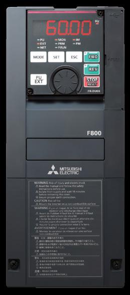
FR-F 800 INVERTER FR-F800 Energy saving Functions ideal for fans and pumps
 INVERTER FACTORY AUTOMATION FR-F800 Enhanced Next-Generation Energy-Saving Inverter [Ethernet communication model added to the line-up] Energy saving Functions ideal for fans and pumps Security & safety
ROLL TO ROLL FUNCTION MANUAL FR-A (0.4K)-04750(90K)-R2R FR-A (0.4K)-06830(280K)-R2R FR-A (315K)-12120(500K)-R2R
-04750(90K)-R2R FR-A (0.4K)-06830(280K)-R2R FR-A (315K)-12120(500K)-R2R") INVERTER ROLL TO ROLL FUNCTION MANUAL FR-A820-00046(0.4K)-04750(90K)-R2R FR-A840-00023(0.4K)-06830(280K)-R2R FR-A842-07700(315K)-12120(500K)-R2R Roll to Roll Function The FR-A800-R2R inverter has dedicated
INVERTER ROLL TO ROLL FUNCTION MANUAL FR-A820-00046(0.4K)-04750(90K)-R2R FR-A840-00023(0.4K)-06830(280K)-R2R FR-A842-07700(315K)-12120(500K)-R2R Roll to Roll Function The FR-A800-R2R inverter has dedicated
INVERTER FR-A800 Plus
 INVERTER FR-A800 Plus FACTORY AUTOMATION The optimum functions for roll to roll applications are added. for Roll to Roll System simplification Wide range of applications Easy startup and adjustment Global
INVERTER FR-D700. Global standard FACTORY AUTOMATION. Pursuing the easy operation. Long life and simple maintenance. Compact and space-saving
 FACTORY AUTOMATION INVERTER FR-D700 Global standard Pursuing the easy operation Long life and simple maintenance Compact and space-saving Supporting various applications Global Player GLOBAL IMPACT OF
ADJUSTABLE SPEED DRIVES FS1
 ADJUSTABLE SPEED DRIVES FS1 Now Available With LonWorks BACnet & MetasysN2 FS1 Model FLA & Dimensions (in.)/ Weight (lbs.) VOLTAGE HP MODEL NUMBER FLA FRAME Dimensions (in.) SHIPPING H W D WEIGHT (lbs.)
FUJI Inverter. Standard Specifications
 FUJI Inverter o Standard Specifications Norminal applied motor The rated output of a general-purpose motor, stated in kw. That is used as a standard motor. Rated capacity The rating of an output capacity,
Brake resistor can be connected. 150%/1Hz high starting torque by General -purpose magnetic flux vector control. Safety stop function
 Features 1 Highly reliable inverter! Compact yet equipped with highest level of function/performance!! Standard specifications 5 Safety stop function (1) (1) The FR-D700 series is compliant to the EU Machinery
INVERTER FREQROL-CS80
 FACTORY AUTOMATION INVERTER FREQROL-CS80 COMPACT & SMART Global Player GLOBAL IMPACT OF MITSUBISHI ELECTRIC Through Mitsubishi Electric s vision, Changes for the Better are possible for a brighter future.
AV-300i Specifications. Saftronics Inc. PC10 Product Specifications PC10. Mini Vector AC Drive
 Saftronics Inc. www.saftronics.com TM AV-300i Specifications PC10 Product Specifications PC10 Mini Vector AC Drive 1 (1) T hree-phas e 230V input Drive Hp 1/8 1/4 1/2 1 2 3 5 7.5 10 Nominal applicable
S11 Adjustable Speed Drive Engineering Specification
 PART 1 - GENERAL 1.0 Scope This specification shall cover Toshiba S11 AC Variable Frequency Drives, 6 pulse for 3- phase 200-240VAC, 380-500VAC and single phase 200V to 240VAC. 1.1 References A. National
SJ700 series High performance with Many useful Functions and, yet User Friendly. WJ200 series Pursuing the Ideal Compact Inverter NEW
 WJ200 series Pursuing the Ideal Compact Inverter NEW SJ700 series High performance with Many useful Functions and, yet User Friendly X200 series Simple, Trip-suppression and Eco-friendly Compact Inverter
VF-nC1 Adjustable Speed Drive Engineering Specification
 PART 1 - GENERAL 1.0 Scope This specification shall cover Toshiba VF-nC1 AC Variable Frequency Drives, 6 pulse for 100V single-phase 0.1 to 0.75kW, 200V single-phase 0.2 to 2.2kW and 200V threephase 0.1
ADJUSTABLE SPEED DRIVES VF-S11 Sords Electric
 ADJUSTABLE SPEED DRIVES VF-S11 The Next Generation of Micro Inverters is Here. The S11 provides maximum torque with precise speed control. It features an easy-to-use, quiet and compact design. In addition,
TOSVERT TM VF-nC3 Parameter List
 TOSVERT TM VF-nC Parameter List E658664 - Setting information * Please fill it in if necessary. Item Content Item Content Setting date / person Customer Application Application model Motor manufacturer
All-rounder with a compact body (Addition of Ethernet communication function models) Easy operability. Extensive option lineup. Ensured maintenance
 Easy operability. Extensive option lineup. Ensured maintenance") INVERTER FR-E700 FACTORY AUTOMATION All-rounder with a compact body (Addition of Ethernet communication function models) Top level of driving performance in compact body Easy operability Extensive option
INVERTER FR-E700 FACTORY AUTOMATION All-rounder with a compact body (Addition of Ethernet communication function models) Top level of driving performance in compact body Easy operability Extensive option
A700 Series. Variable Frequency Drives UNSURPASSED POWER AND CONTROL 1 /2-700 HP
 A700 Series Variable Frequency Drives UNSURPASSED POWER AND CONTROL 1 /2-700 HP The amazing new A700 Mitsubishi Electric s RSV technology gives you class-leading power, control and flexibility. What makes
E3 Adjustable Speed Drive Engineering Specification
 E3 Adjustable Speed Drive Engineering Specification PART 1 - GENERAL 1.0 Scope This specification shall cover Toshiba E3 AC Variable Frequency Drives, 6 pulse for 230V and 460V. 1.1 References A. National
General Specifications FECA-TE /2010. Phone: Fax: Web:
 General Specifications FECA-TE-117 06/2010 1. Standard Specifications 1) Three-phase 230V series Output ratings Input ratings Braking Item Specifications Type (FRN C1S-2U) F12 F25 F50 001 002 003 005 Nominal
System configuration. Ratings 400 V Class three-phase 90 to 800 kw 690 V Class three-phase 90 to 1000 kw SX-D. Frequency inverters.
 ~ ~ SX High performance Vector Control IP54 full range. Compact design & Robustness Built-in Filter according to C3 Class Built-in Fusses (From 200 kw) Safety according EN13849-1 and EN62061 standards
P-SERIES VFD 1-40HP (200~230VAC), 1-400HP (380~480VAC),3Ø Dual Rated for Constant & Variable Torque Integrated PID Control
, 1-400HP (380~480VAC),3Ø Dual Rated for Constant & Variable Torque Integrated PID Control") P-SERIES VFD 1-40HP (200~230VAC), 1-400HP (380~480VAC),3Ø Dual Rated for Constant & Variable Torque Integrated PID Control NEW FIRMWARE MAKES SETUP A SNAP Application based commissioning allows parameters
P-SERIES VFD 1-40HP (200~230VAC), 1-400HP (380~480VAC),3Ø Dual Rated for Constant & Variable Torque Integrated PID Control NEW FIRMWARE MAKES SETUP A SNAP Application based commissioning allows parameters
Power Regenerative Converter, THYFREC CV240S
 Development of New Products Power Regenerative Converter, THYFREC CV240S Harmonic restraint, Power regeneration, 120 conduction, Power factor improvement, Common converter system, Environment compatibility
Index 2. G Gain settings 4 31 Glossary of terms A 2 Grommets 2 13
 Index A A Group functions 3 9 AC reactors 5 3 Acceleration 1 15, 3 8 characteristic curves 3 26 second function 3 24 two-stage 4 19 Acceleration stop function 3 21 Access levels 3 5, 3 36, 4 25 Access
Fan and Pump AC Inverter
 Fan and Pump AC Inverter Key Features for Fan and Pump Applications PID and Auto Energy Saving Functions. Input Phase Loss and Output Phase Loss Protection. LCD Keypad can be used to copy parameter settings
Highest level in your hand
 Product Information FREQUENCY INVERTER Highest level in your hand SPEED UP INTELLIGENT DESIGN MORE FLEXIBILITY Comprehensive functions to guarantee faster production cycles with outstanding speed constancy
SX (690 V) System configuration
 System configuration") SX (690 V) High performance Vector Control IP54 full range Compact design & Robustness Built-in Filter according to C3 Class Built-in Fuses (From 200 kw) Safety according EN13849-1 and EN62061 standards
SX (690 V) High performance Vector Control IP54 full range Compact design & Robustness Built-in Filter according to C3 Class Built-in Fuses (From 200 kw) Safety according EN13849-1 and EN62061 standards
ADJUSTABLE SPEED DRIVES. AS1 Drive
 ADJUSTABLE SPEED DRIVES AS1 Drive Toshiba s New ASD Product Line The AS1 drive builds on Toshiba s history of supplying powerful, reliable, and versatile drives. We have combined our best drive features
SX (400V) System configuration
 System configuration") ~ ~ SX (400V) High performance Vector Control IP54 full range. Compact design & Robustness Built-in Filter according to C3 Class Built-in Fusses (From 200 kw) Safety according EN13849-1 and EN62061 standards
~ ~ SX (400V) High performance Vector Control IP54 full range. Compact design & Robustness Built-in Filter according to C3 Class Built-in Fusses (From 200 kw) Safety according EN13849-1 and EN62061 standards
WJ200 series Pursuing the Ideal Compact Inverter
 WJ200 series Pursuing the Ideal Compact Inverter X200 series Simple, Trip-suppression and Eco-friendly Compact Inverter NE-S1 series Economical Inverter with Simple Operation SJ700B series Inverter designed
SX (400 V) System configuration
 System configuration") ~ ~ SX (400 V) High performance Vector Control IP54 full range. Compact design & Robustness Built-in Filter according to C3 Class Built-in Fuses (From 200 kw) Safety according EN13849-1 and EN62061 standards
~ ~ SX (400 V) High performance Vector Control IP54 full range. Compact design & Robustness Built-in Filter according to C3 Class Built-in Fuses (From 200 kw) Safety according EN13849-1 and EN62061 standards
D SERIES EM16 IP 20 / NEMA 1 & IP 66 / NEMA 4X COMPACT VECTOR CONTROL DRIVE EM 16 COMPACT VECTOR CONTROL DRIVE
 D SERIES EM16 IP 20 / NEMA 1 & IP 66 / NEMA 4X COMPACT VECTOR CONTROL DRIVE EM 16 COMPACT VECTOR CONTROL DRIVE 1 2 SERIES 1 2 pag. 4 pag. 5 Applications Model identification 3 pag. 5 4 pag. 6 Capacity
Multi-function, Compact Inverters. 3G3MV Series
 Multi-function, Compact Inverters 3G3MV Series There has been a great demand for inverters with more functions and easier motor control than conventional i OMRON's powerful, compact 3G3MV Series with versat
INVERTER FR-F700P INSTRUCTION MANUAL (BASIC)
") INVERTER FR-F700P INSTRUCTION MANUAL (BASIC) FR-F720P-0.75K to 110K FR-F740P-0.75K to 560K Thank you for choosing this Mitsubishi Inverter. This Instruction Manual (Basic) is intended for users who "just
INVERTER FR-F700P INSTRUCTION MANUAL (BASIC) FR-F720P-0.75K to 110K FR-F740P-0.75K to 560K Thank you for choosing this Mitsubishi Inverter. This Instruction Manual (Basic) is intended for users who "just
D SERIES LM16. COMPACT DRIVE V/f and SLV CONTROL. LM16 COMPACT DRIVE V/f and SLV CONTROL
 D SERIES LM16 COMPACT DRIVE V/f and SLV CONTROL LM16 COMPACT DRIVE V/f and SLV CONTROL 1 2 SERIES 1 2 page 4 page 6 Introduction Fields of application 3 page 7 4 page 8 Designation Product offer 5 6 page
6.9 Jump frequency - Avoiding frequency resonance
 E581595.9 Jump frequency - Avoiding frequency resonance : Jump frequency : Jumping width Function Resonance due to the natural frequency of the mechanical system can be avoided by jumping the resonant
High-performance Vector-type SF-G Series Inverter
 SF-G Series 5.5-160KW Quality and Innovation Industrial Upgrading High-performance ector-type SF-G Series Inverter Superior Performance just for your ISO 14001 BSMI ISO 9001 BSMI 認可登錄 REGISTERED CERT.
INVERTER FR-A700 INSTRUCTION MANUAL (BASIC) FR-A K to 90K FR-A K to 500K
 FR-A K to 90K FR-A K to 500K") INVERTER FR-A700 INSTRUCTION MANUAL (BASIC) FR-A720-0.4K to 90K FR-A740-0.4K to 500K Thank you for choosing this Mitsubishi Inverter. This Instruction Manual (Basic) is intended for users who "just want
INVERTER FR-A700 INSTRUCTION MANUAL (BASIC) FR-A720-0.4K to 90K FR-A740-0.4K to 500K Thank you for choosing this Mitsubishi Inverter. This Instruction Manual (Basic) is intended for users who "just want
The new Yaskawa Varispeed G7 Inverter
 The new Yaskawa Varispeed G7 Inverter Unique new 3-level PWM flux vector Constant or variable torque applications control method 0.4 kw to 300 kw power range Exceptional low speed/high torque control Quick
ADVANCED AND EVER ADVANCING FR-V200. FR-V200 series
 ADVANCED AND EVER ADVANCING FR-V200 FR-V200 series CONTENTS 1 SPECIFICATIONS 1 1.1 OPERATION PRINCIPLE...1 1.1.1 What is vector control?...1 1.2 Instructions for Using the Inverter...3 1.3 Specification
A700 Series. Variable Frequency Drives
 A700 Series Variable Frequency Drives UNSURPASSED POWER AND CONTROL The amazing new A700 Mitsubishi Electric s RSV technology gives you class-leading power, control and flexibility. What makes RSV (Real
G+ Mini Transition Guide. Product Transition Guide P3 Series 2 to G+ Mini
 Transition Guide Product Transition Guide to Rev: Page Intentionally Left Blank Transition Guide September 2008 Page 2 of 24 Table of Contents 1.1 Overview...4 1.2 Drive Replacement Checklist...4 1.3 Ratings
Before you operate the inverter, the parameters that you must first program are the basic parameters.
 . Main parameters Before you operate the inverter, the parameters that you must first program are the basic parameters..1 Searching for changes using the history function () : History function History
Variable Frequency Drive / Inverter (0.4 ~ 280kW)
") Variable Frequency Drive / Inverter (0.4 ~ 280kW) & Standard Features Configuration Comparison Comparison Table Enclosure IP00 IP20 NEMA 1 Rating Single phase 0.4 2.2kW 0.4 1.5kW Three phase 0.4 4kW Constant
Variable Frequency Drive / Inverter (0.4 ~ 280kW) & Standard Features Configuration Comparison Comparison Table Enclosure IP00 IP20 NEMA 1 Rating Single phase 0.4 2.2kW 0.4 1.5kW Three phase 0.4 4kW Constant
ADJUSTABLE SPEED DRIVES. HX7 Series. 18 Pulse. Phone: Fax: Web: -
 ADJUSTABLE SPEED DRIVES HX7 Series 18 Pulse Toshiba HX7 In some industrial applications, users need reliable and efficient adjustable speed drives that do not contribute significant harmonic distortion
FR-F K to 55K FR-F K to 55K(-EC) FR-F520-11K to 55K-NA FR-F540-11K to 55K-NA
 FR-F520-11K to 55K-NA FR-F540-11K to 55K-NA") TRANSISTORIZED INVERTER FR-F500 INSTRUCTION MANUAL FR-F520-0.75K to 55K FR-F540-0.75K to 55K(-EC) FR-F520-11K to 55K-NA FR-F540-11K to 55K-NA OUTLINE INSTALLATION AND WIRING OPERATION/ CONTROL Chapter
TRANSISTORIZED INVERTER FR-F500 INSTRUCTION MANUAL FR-F520-0.75K to 55K FR-F540-0.75K to 55K(-EC) FR-F520-11K to 55K-NA FR-F540-11K to 55K-NA OUTLINE INSTALLATION AND WIRING OPERATION/ CONTROL Chapter
ADJUSTABLE SPEED DRIVES. W7 Series. 18 Pulse
 ADJUSTABLE SPEED DRIVES W7 Series 18 Pulse Meets or Exceeds Your Specifications Standard Specifications Item Voltage Class 460V Maximum HP 60 75 100 125 150 200 250 300 400 500 600 700 800 Drive Rating
TECO F510 Inverter. Quick Start Guide. Step 1. Supply & Motor connection
 Quick Start Guide TECO F510 Inverter This guide is to assist you in installing and running the inverter and verify that it is functioning correctly for it s main and basic features. For detailed information
[ 4 ] Using pulse train input (F01 = 12)
![[ 4 ] Using pulse train input (F01 = 12)](/thumbs/90/102625444.jpg "[ 4 ] Using pulse train input (F01 = 12)") [ 4 ] Using pulse train input (F01 = 12) Selecting the pulse train input format (d59) A pulse train in the format selected by the function code d59 can give a frequency command to the inverter. Three types
[ 4 ] Using pulse train input (F01 = 12) Selecting the pulse train input format (d59) A pulse train in the format selected by the function code d59 can give a frequency command to the inverter. Three types
13. Before making a service call Trip information and remedies
 . Before making a service call Trip information and remedies.1 Trip causes/warnings and remedies When a problem arises, diagnose it in accordance with the following table. If it is found that replacement
AV-300i Specifications. Saftronics Inc. VG10 Product Specifications VG10. Dynamic Vector Drive
 Saftronics Inc. www.saftronics.com TM AV-300i Specifications VG10 Product Specifications VG10 Dynamic Vector Drive 1 Category Item Description Nominal Motor 230 VAC, 3 Phase 1/4 Hp to 125 Hp 460 VAC, 3
CHAPTER 8 PARAMETER SUMMARY
 CHAPTER PARAMETER SUMMARY Group 0: System Parameter VFD-V Series 00-00 Identity Code Based on the model type 00-01 Rated Current Display 00-02 Parameter Reset 00-03 00-04 Star-up Display of the Drive Definitions
VARIABLE FREQUENCY DRIVES A500 SERIES ADVANCED INTELLIGENT CONTROL. cul. Modbus plus. Device Net
 RIBLE FREQUENCY DRIES 500 SERIES DNCED INTELLIGENT CONTROL UL cul CE Modbus plus Device Net Profibus DP CC-Link The Culmination of Mitsubishi s Expertise Reaches into the Realms of dvanced Technology Expanding
INSTRUCTION MANUAL (BASIC)
") TRANSISTORIZED INVERTER FR-S500 INSTRUCTION MANUAL (BASIC) FR-S540E-0.4K to 3.7K-EC FR-S520SE-0.2K to 1.5K-EC Thank you for choosing this Mitsubishi transistorized inverter. If this is the first time for
TRANSISTORIZED INVERTER FR-S500 INSTRUCTION MANUAL (BASIC) FR-S540E-0.4K to 3.7K-EC FR-S520SE-0.2K to 1.5K-EC Thank you for choosing this Mitsubishi transistorized inverter. If this is the first time for
FR-D K to 15K FR-D K to 15K FR-D720S-0.1K to 2.2K FR-D710W-0.1K to 0.75K
 INVERTER FR-D700 INSTRUCTION MANUAL (Applied) FR-D720-0.1K to 15K FR-D740-0.4K to 15K FR-D720S-0.1K to 2.2K FR-D710W-0.1K to 0.75K OUTLINE WIRING 1 2 PRECAUTIONS FOR USE OF THE INVERTER 3 PARAMETERS 4
CONTENTS PRODUCT CHECKING AND PARTS IDENTIFICATION... 1 INSTALLATION AND WIRING... 2
 PRESSURE-RESISTANT, EXPLOSION-PROOF MOTOR DRIVING INVERTER FR-B, B3 INSTRUCTION MANUAL (BASIC) FR-B-75 75K(200V), FR-B-75 110K(400V) FR-B3-(N)(H) 40 37K (A700 SPECIFICATIONS) Thank you for choosing this
FR-A K - 55K (-NA) FR-A K - 55K (-NA) (-EC)
 FR-A K - 55K (-NA) (-EC)") MITSUBISHI ELECTRIC FR-A 500 Frequency Inverter Instruction Manual FR-A 520 0.4K - 55K (-NA) FR-A 540 0.4K - 55K (-NA) (-EC) Art.No.: 69633 2001 03 02 IB 66790-G MITSUBISHI ELECTRIC INDUSTRIAL AUTOMATION
MITSUBISHI ELECTRIC FR-A 500 Frequency Inverter Instruction Manual FR-A 520 0.4K - 55K (-NA) FR-A 540 0.4K - 55K (-NA) (-EC) Art.No.: 69633 2001 03 02 IB 66790-G MITSUBISHI ELECTRIC INDUSTRIAL AUTOMATION
ADJUSTABLE SPEED DRIVES. HX7 Series. 18-Pulse
 ADJUSTABLE SPEED DRIVES HX7 Series 18-Pulse Toshiba HX7 In some industrial applications, users need reliable and efficient adjustable speed drives that do not contribute significant harmonic distortion
MR-J4-DU_B_-LL SERVO AMPLIFIER INSTRUCTION MANUAL
 General-Purpose AC Servo SSCNET /H Interface AC Servo for Pressure Control MODEL (SERVO AMPLIFIER) MR-J4-_B_-LL MODEL (DRIVE UNIT) MR-J4-DU_B_-LL SERVO AMPLIFIER INSTRUCTION MANUAL Safety Instructions
INVERTER. Model FR-E700. All-rounder. Compact body. Easy for anybody and high performance
 INVERTER Model FR-E7 Remarkable usability Top level driving performance! Compact body All-rounder Easy for anybody and high performance Features 1 Top level driving performance in compact body The inverter
INVERTER FR-D700 INSTALLATION GUIDELINE FR-D (SC) to 160(SC)-EC FR-D720S-008(SC) to 100(SC)-EC
 to 160(SC)-EC FR-D720S-008(SC) to 100(SC)-EC") INVERTER FR-D700 INSTALLATION GUIDELINE FR-D740-012(SC) to 160(SC)-EC FR-D720S-008(SC) to 100(SC)-EC Thank you for choosing this Mitsubishi Inverter. Please read through this Installation Guideline and
INVERTER FR-D700 INSTALLATION GUIDELINE FR-D740-012(SC) to 160(SC)-EC FR-D720S-008(SC) to 100(SC)-EC Thank you for choosing this Mitsubishi Inverter. Please read through this Installation Guideline and
INVERTER FR-F700PJ INSTRUCTION MANUAL (BASIC) FR-F720PJ-0.4K to 15K (F) FR-F740PJ-0.4K to 15K (F)
 FR-F720PJ-0.4K to 15K (F) FR-F740PJ-0.4K to 15K (F)") INVERTER FR-F700PJ INSTRUCTION MANUAL (BASIC) FR-F720PJ-0.4K to 15K (F) FR-F740PJ-0.4K to 15K (F) Thank you for choosing this Mitsubishi Electric Inverter. This Instruction Manual (Basic) provides handling
INVERTER FR-F700PJ INSTRUCTION MANUAL (BASIC) FR-F720PJ-0.4K to 15K (F) FR-F740PJ-0.4K to 15K (F) Thank you for choosing this Mitsubishi Electric Inverter. This Instruction Manual (Basic) provides handling
Frequency Inverters. SJ700B Series. Powerful Inverter for General Purpose Use. SJ700B Series
 Frequency Inverters Frequency Inverters High performance, powerful functions, user friendly. A powerful drive with high starting torque and easy configuration Improved Sensorless Vector Control and Auto
SECTION 16483D ADJUSTABLE FREQUENCY DRIVE - MICRODRIVE (MVX <10-HP)
") ADJUSTABLE FREQUENCY DRIVE - MICRODRIVE (MVX
ADJUSTABLE FREQUENCY DRIVE - MICRODRIVE (MVX
Drive Safety integrated AC servo amplifier <MR-J3- S 0.1kW to 55kW> Safety logic unit <MR-J3-D05>
 General-Purpose AC Servo MELSERVO-J3 Drive Safety integrated AC servo amplifier Safety logic unit The MR-J3- S Drive Safety integrated AC servo amplifier (SSCNET Ⅲ
FR-F520J-0.4K to 15K (F) FR-F540J-0.4K to 15K (F)
 FR-F540J-0.4K to 15K (F)") TRANSISTORIZED INVERTER FR-F500J INSTRUCTION MANUAL (Detailed) AIR-CONDITIONING INVERTER FR-F520J-0.4K to 15K (F) FR-F540J-0.4K to 15K (F) WIRING Chapter 1 FUNCTIONS Chapter 2 PROTECTIVE FUNCTIONS Chapter
TRANSISTORIZED INVERTER FR-F500J INSTRUCTION MANUAL (Detailed) AIR-CONDITIONING INVERTER FR-F520J-0.4K to 15K (F) FR-F540J-0.4K to 15K (F) WIRING Chapter 1 FUNCTIONS Chapter 2 PROTECTIVE FUNCTIONS Chapter
INSTRUCTION MANUAL (BASIC) FR-F520J-0.4K to 15K(F) FR-F540J-0.4K to 15K(F)
 FR-F520J-0.4K to 15K(F) FR-F540J-0.4K to 15K(F)") TRANSISTORIZED INVERTER FR-F500J INSTRUCTION MANUAL (BASIC) FR-F520J-0.4K to 15K(F) FR-F540J-0.4K to 15K(F) Thank you for choosing this Mitsubishi Transistorized inverter. If this is the first time for
TRANSISTORIZED INVERTER FR-F500J INSTRUCTION MANUAL (BASIC) FR-F520J-0.4K to 15K(F) FR-F540J-0.4K to 15K(F) Thank you for choosing this Mitsubishi Transistorized inverter. If this is the first time for
This section is specifically about safety matters WARNING CAUTION WARNING
 6 4 ) 5 1 5 6 4 1 -, 1 8-4 6-4. 4 5 # 1 5 6 4 7 + 6 1 ) 7 ), A J = E 5 1 2-1 8-4 6-4. 4 5 # J +! % 4. 4 5 # J! % ) 4. 4 5 # 5 J # 4. 4 5 # 5 J # - + 4 9 1 4 1 / + D = F J A H. 7 + 6 1 5 + D = F J A H 2
AF91 Adjustable Frequency Drives Series B
 Effective: January, 00 Page New Information AF9 Adjustable Model AF9 Description Model AF9 Adjustable Frequency AC Drives are designed to provide adjustable speed control of -phase motors. These microprocessor-based
Caution. Three-phase 400V series FRN0.4C1S-4A FRN0.75C1S-4A FRN1.5C1S-4A FRN2.2C1S-4A FRN3.7C1S-4A
 Variation Caution The contents of this catalog are provided to help you select the product model that is best for you. Before actual use, be sure to read the User s Manual thoroughly to assure correct
General Purpose Drives
 AC Variable Speed Drive General Purpose Drives Dedicated to Low Power Applications 0.37kW 11kW / 0.5HP 15HP 200 480V 3 Phase Input AC Variable Speed Drive 0.37kW 11kW / 0.5HP 15HP 110 480V Single & 3 Phase
Superior performance just for you
 www.seec.com.tw Compact Design Vector Control SS2 Series Inverter Superior performance just for you (0.4KW-5.5KW) ISO 14001 BSMI REGISTERED CERT. NO. 4A4E003 ISO 9001 BSMI REGISTERED CERT. NO. 4A4Y003
INVERTER A800 FR-A802 (SEPARATED CONVERTER TYPE) INSTRUCTION MANUAL (HARDWARE)
 INSTRUCTION MANUAL (HARDWARE)") INVERTER A800 FR-A802 (SEPARATED CONVERTER TYPE) INSTRUCTION MANUAL (HARDWARE) FR-A842-07700(315K) to 12120(500K) INTRODUCTION 1 INSTALLATION AND WIRING 2 PRECAUTIONS FOR USE OF THE INVERTER 3 PROTECTIVE
INVERTER A800 FR-A802 (SEPARATED CONVERTER TYPE) INSTRUCTION MANUAL (HARDWARE) FR-A842-07700(315K) to 12120(500K) INTRODUCTION 1 INSTALLATION AND WIRING 2 PRECAUTIONS FOR USE OF THE INVERTER 3 PROTECTIVE
Manual Overview...1 2
 GETTING STARTED CHAPTER 1 Contents of this Chapter... Manual Overview.....................................1 2 Overview of this Publication..................................1 2 Who Should Read This Manual...............................1
HPVFP High Performance Full Function Vector Frequency Inverter
 Advanced User Manual HPVFP High Performance Full Function Vector Frequency Inverter HP VER 1.00 1. HPVFP Parameter Set Overview...3 1.1. About this section...3 1.2. Parameter Structure Overview...3 1.3.
VFS11 Parameter List for up to CPU version 105
 E65824 VFS Parameter List for up to CPU version 5 Setting Date Customer End user Application Application No/Serial No Inverter s Type-Form Quantity Inverter s Serial No Motor s capacity If user s value
α α Retry count clear Alarm reset Active End of retry S-curve time during accelerati on H04: (Count) setting S curve time during decelerati on
 setting S curve time during decelerati on") Upon success of retry Alarm Occurrence Disappearance Time S-curve acceleration/deceleration To reduce the shock of the mechanical system, the change in the output frequency is made smooth when the frequency
Upon success of retry Alarm Occurrence Disappearance Time S-curve acceleration/deceleration To reduce the shock of the mechanical system, the change in the output frequency is made smooth when the frequency
SJ100 Series Inverter Quick Reference Guide. Single-phase Input 200V Class Three-phase Input 200V Class Three-phase Input 400V Class
 HITACHI SJ1 Series Inverter Quick Reference Guide Single-phase Input 2V Class Three-phase Input 2V Class Three-phase Input 4V Class Hitachi Industrial Equipment Systems Co., Ltd. Manual No. NB5821XD Dec.
ATV12H037F1 variable speed drive ATV kW hp V - 1ph - with heat sink
 Characteristics variable speed drive ATV12-0.37kW - 0.55hp - 100..120V - 1ph - with heat sink Main Range of product Altivar 12 Product or component type Product destination Product specific application
Inverter Drive /Vector Drive Motors & Controls
 H2 Inverter/ Encoderless Vector Inverter Drive /Vector Drive & Controls 3/4 thru 50 180-264 VAC 3 Phase - 50/60 Hz 3/4 thru 60 340-528 VAC 3 Phase - 50/60 Hz 3/4 thru 60 515-660 VAC 3 Phase - 60 Hz HVAC
MR-J4-_B-RJ010 MR-J4-_B4-RJ010 MR-J3-T10 SERVO AMPLIFIER INSTRUCTION MANUAL. General-Purpose AC Servo
 General-Purpose AC Servo CC-Link IE Field Network interface with Motion MODEL (Servo amplifier) MR-J4-_B-RJ010 MR-J4-_B4-RJ010 MODEL (CC-Link IE Field Network interface unit) MR-J3-T10 SERVO AMPLIFIER
SJ series P1 High performance inverter with innovative ease-of-use and excellent driving performance
 NEW NE-S1 series Economical Inverter with Simple Operation SJ series P1 High performance inverter with innovative ease-of-use and excellent driving performance WJ200 series Pursuing the Ideal Compact Inverter
ATV12HU40M3 variable speed drive ATV12-4kW - 5hp V - 3ph - with heat sink
 Characteristics variable speed drive ATV12-4kW - 5hp - 200..240V - 3ph - with heat sink Main Range of product Altivar 12 Product or component type Product destination Product specific application Assembly
HITACHI. L100-M Series Inverter Quick Reference Guide. Hitachi Industrial Equipment Systems Co., Ltd. Single-phase Input 100V Class
 HITACHI L1-M Series Inverter Quick Reference Guide Single-phase Input 1V Class Hitachi Industrial Equipment Systems Co., Ltd. Manual No. NB5741XD December 23 Caution: Be sure to read the L1 Inverter Manual
FR-S520E-0.1K to 3.7K-NA FR-S540E-0.4K to 3.7K-NA FR-S510WE-0.1K to 0.75K-NA
 TRANSISTORIZED INVERTER FR-S500 INSTRUCTION MANUAL (Detailed) SIMPLE INVERTER FR-S520E-0.1K to 3.7K-NA FR-S540E-0.4K to 3.7K-NA FR-S510WE-0.1K to 0.75K-NA WIRING Chapter 1 FUNCTIONS Chapter 2 PROTECTIVE
ATV12H018F1 variable speed drive ATV kW hp V - 1ph
 Characteristics variable speed drive ATV12-0.18kW - 0.25hp - 100..120V - 1ph Main Range of product Altivar 12 Product or component type Product destination Product specific application Assembly style Component
TAC ATV38, IP55. Variable Speed Drives for Asynchronous Motors. 3-phase. 380/460 V, Hz
 TAC ATV8, IP55 Variable Speed Drives for Asynchronous Motors. -phase. 80/460 V, 50-60 Hz E-60-24 24 May 2004 ATV 8 IP55 drives are specifically designed for pump and fan applications powered by a three-phase
Softstarters. Specification guide. Type PST. Low Voltage Products & Systems
 Softstarters Type PST Low Voltage Products & Systems 2 Low Voltage Products & Systems 1SXU132171M0201 [AC 1006.8] - 5/03 ABB Inc. 888-385-1221 www.abb.com/lowvoltage Softstarters Type PST Specification
FR-E KNC to 15KNC FR-E KNC to 15KNC FR-E720S-0.1KNC to 2.2KNC
 INVERTER FR-E700 INSTRUCTION MANUAL (Applied) CC-Link communication function FR-E720-0.1KNC to 15KNC FR-E740-0.4KNC to 15KNC FR-E720S-0.1KNC to 2.2KNC OUTLINE WIRING 1 2 PRECAUTIONS FOR USE OF THE INVERTER
CTi Automation - Phone: Fax: Web: -
 CONTENTS Chapter 1 Specifications 1. Standard Specifications... 1-2 1.1 Three-phase 230V FRENIC5000G11S Series... 1-2 1.2 Three-phase 460V FRENIC5000G11S Series... 1-3 1.3 Three-phase 230V FRENIC5000P11S
Operating Instructions
 4XH35QB151210 Small General Frequency Converter Operating Instructions 220V 0.75KW 5.5KW 400V 0.75KW 15KW Please read the instruction carefully and understand the contents so that it can be installed and
High Performance Vector control SE2 Series Inverter
 SE2 Series www.seec.com.tw High Performance Vector control SE2 Series Inverter ISO 14001 BSMI REGISTERED CERT. NO. 4A4E003 ISO 9001 BSMI REGISTERED CERT. NO. 4A4Y003 Feature Feature High-performance senseless
1. Institute of Electrical and Electronic Engineers (IEEE) a. Standard , IEEE Guide for Harmonic Content and Control.
 a. Standard , IEEE Guide for Harmonic Content and Control.") Section 16680 VARIABLE SPEED DRIVE SYSTEMS OR AFD Part I - GENERAL I.01 Description A. This specification is to cover a complete adjustable frequency motor drive consisting of a pulse width modulated (PWM)
Section 16680 VARIABLE SPEED DRIVE SYSTEMS OR AFD Part I - GENERAL I.01 Description A. This specification is to cover a complete adjustable frequency motor drive consisting of a pulse width modulated (PWM)
Series Concepts. Ideal functions to meet various needs. New, compact design. Simple operation. Flexible through optionals
 MEH441a Series Concepts Ideal functions to meet various needs New, compact design Simple operation Flexible through optionals A broad range of model variations Actual size Global products The FRENIC-Mini
MR-C Servo SERVOMOTORS & AMPLIFIERS. Step Up to Servo Performance
 MR-C Servo SERVOMOTORS & AMPLIFIERS Step Up to Servo Performance Small, Easy-to-Use, High- Performance. An Extraordinarily Compact, Intelligent Servo. The MR-C brushless servo, in a handy super-compact
VFS9 Parameter List for Version110 or later
 VFS9 Parameter List for Version110 or later Setting Date Customer End user Application Application /Serial Inverter s Type-Form Quantity Inverter s Serial Motor s capacity If user s value is same as shipping
General-Purpose AC Servo. MELSERVO-JE Servo amplifier INSTRUCTION MANUAL (TROUBLE SHOOTING)
") General-Purpose AC Servo MELSERVO-JE Servo amplifier INSTRUCTION MANUAL (TROUBLE SHOOTING) F Safety Instructions Please read the instructions carefully before using the equipment. To use the equipment
General-Purpose AC Servo MELSERVO-JE Servo amplifier INSTRUCTION MANUAL (TROUBLE SHOOTING) F Safety Instructions Please read the instructions carefully before using the equipment. To use the equipment
This Chapter contains:
 7 This Chapter contains: Table 7.1 Table 7-2 Table 7-3 Table 7-4 contains the general technical specifications for the MICROMASTER 430 inverter contains terminal tightening torques and the required cooling
IMO Jaguar VXG. Quick Start Guide. Refer to VXG Manual for full data. Available to download from IMO Precision Controls Ltd.
 Quick Start Guide Refer to VXG Manual for full data. Available to download from www.imopc.com. IMO Jaguar VXG Thank you for purchasing our Jaguar VXG series of inverters. This product is designed to drive
Medium Voltage VFD. Perfect Energy Saving Drive 3kV 200kVA ~ 3,700kVA / 4kV 250kVA ~ 4,700kVA 6kV 400kVA ~ 7,500kVA / 10kV 600kVA ~ 11,000kVA
 www.miepl.com/ls Medium Voltage VFD Perfect Energy Saving Drive 3kV 200kVA ~ 3,700kVA / 4kV 250kVA ~ 4,700kVA 6kV 400kVA ~ 7,500kVA / 10kV kva ~ 11,000kVA Perfect Energy Saving Drive The most efficiency