INVERTER FREQROL-CS80
|
|
|
- Marsha Preston
- 6 years ago
- Views:
Transcription


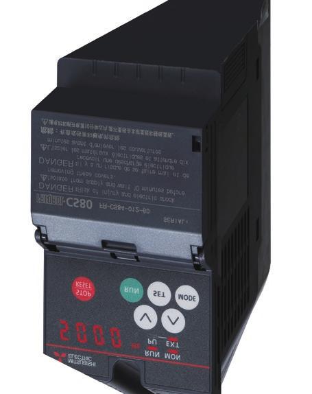
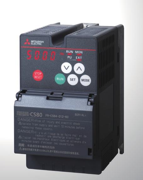
1 FACTORY AUTOMATION INVERTER FREQROL-CS80 COMPACT & SMART

2 Global Player GLOBAL IMPACT OF MITSUBISHI ELECTRIC Through Mitsubishi Electric s vision, Changes for the Better are possible for a brighter future. Mitsubishi Electric is involved in many areas including the following We bring together the best minds to create the best technologies. At Mitsubishi Electric, we understand that technology is the driving force of change in our lives. By bringing greater comfort to daily life, maximizing the efficiency of businesses and keeping things running across society, we integrate technology and innovation to bring changes for the better. Energy and Electric Systems A wide range of power and electrical products from generators to large-scale displays. Electronic Devices A wide portfolio of cutting-edge semiconductor devices for systems and products. Home Appliance Dependable consumer products like air conditioners and home entertainment systems. Information and Communication Systems Commercial and consumer-centric equipment, products and systems. Industrial Automation Systems Maximizing productivity and efficiency with cutting-edge automation technology. 2
3 Contents Features Example Connection Standard Specifications Outline Dimensions Terminal Connection Diagram, Terminal Specifications Explanation of the Control Panel and Parameter Unit FR Configurator2 Parameter List Protective Functions Option and Peripheral Devices Precautions for Operation/Selection, Precautions for Peripheral Device Selection Warranty

 x 129.5 mm (D) <CS80> 128 mm (H) x 68 mm (W) x 117.")

 option can be used.")
4 Features Various Functions in a Small Body Compact and Smart Inverter 1 Features Feature 1 World's smallest class compact body Compact size achieved by the low heat generation design In-house comparison Volume reduction to 57% For the FR-CS <Conventional model> 128 mm (H) x 108 mm (W) x mm (D) <CS80> 128 mm (H) x 68 mm (W) x mm (D) Actual size of the FR-CS Space saving by the side-by-side installation Side-by-side installation is possible*. Three FR-CS inverters can be installed in space for two conventional models to save space. A DIN rail installation attachment (FR-UDA[][]) option can be used. (excluding inverters FR-CS to 295) Conventional model 2 units * Keep the surrounding air temperature of the inverter at 40 C maximum. 4 FR-CS units
5 Features Feature 2 High performance Compact yet high performance General-purpose magnetic flux vector control General-purpose magnetic flux vector control and auto tuning functions are available. These functions ensure the applications that require high starting torque, such as washing machines, agitators, and transfer machines including conveyors, hoists, and elevators. High torque of 150% / 1 Hz is realized (when the slip compensation function is valid). Auto tuning With our "non-rotation" auto tuning function the motor constant (R1) can be automatically calculated. Feature 3 Easy to use Brake unit connection Brake unit can be connected using terminal P/+ and terminal N/-. It is useful for applications require regenerative braking torque during deceleration, such as transfer machines and food machines. Option CS80 When using the inverter with the brake unit, use the FR-CS or higher capacity inverter. Optimum excitation control The excitation current is constantly adjusted to its optimum value to drive the motor most efficiently. With a small load torque, a substantial energy saving can be achieved. P/+ N/- Brake resistor FR-BR P/+ PR PR P/+ N/- Brake unit FR-BU2 1 Features Easy-to-read operation panel Operation panel FR-LU08 An optional LCD operation panel (FR-LU08) is also available. Option Enclosure surface operation panel FR-PA07 The operation panel enables inverter operation and monitoring of frequency setting from the enclosure surface. Option Parameter unit FR-PU07 Option The parameter unit features helpful settings such as direct input with ten-key pad, operating status display, and help function. Eight languages are supported. Parameter settings for up to three units can be saved. The operation panel cannot be removed from the inverter. The separate parameter unit connection cable (FR-CB20[]) is required. To connect the FR-LU08, the operation panel connection connector (FR-ADP) is also required. Shorter startup time with easy setup Inverter setup software FR Configurator2 Option The software is easy to use and has unity as Mitsubishi Electric FA products with MELSOFT common design and good operability. Free trial version, which contains start-up functions, is available. It can be downloaded at Mitsubishi Electric FA Global Website. Personal computer FR Configurator2 Supporting high-speed communication RS-485 communication Using a controller, the inverter can be controlled and monitored via network. The standard model with an RS-485 interface (Mitsubishi inverter protocol, MODBUS RTU protocol) enables communication with the speed of up to kbps. Conventional model CS kbps kbps Easy-to-follow display improves the operability Easy connection with GOT When the automatic connection is enabled, the inverter can communicate with the GOT2000 series simply by connecting the GOT. RS-485 communication 5


6 Features 1 Features Feature 4 Easy maintenance Reduced wiring check time The wiring can be checked only by lifting the control terminal cover, which makes maintenance work easier. Easy wiring to the control circuit Spring clamp terminals (control circuit terminals) Spring clamp terminals* 1 provide high reliability and easy wiring. *1: The main circuit terminals are screw terminals. Easy wiring Wiring is completed only by inserting the dedicated blade terminal of each cable. Without using the blade terminal, the loose wires can also be connected using a flathead screwdriver. Easy wiring. Just insert. High reliability Internal terminal contacts are spring-type. Therefore, wires can be protected against loosening or contact faults due to vibrations during operation on a bogie or during transport. Maintenance-free No additional screw tightening is required. Assures the tensile strength of the DIN standards. (Example: transport of the inverters) Protected in hazardous environments The circuit board coating conforms to IEC C2/3S2 for improved environmental resistance. 6 Front Back
7 Features Lineup FR-CS Symbol 2 4 Voltage class 200 V class 400 V class Symbol Power supply None Three-phase S Single-phase Symbol 012 to 295 Description Inverter rated current (A) Symbol 60 Circuit board coating (conforming to IEC C2/3S2) With Features Power supply Inverter model Three-phase 400 V FR-CS84-[]-60 Power supply Inverter model Single-phase 200 V FR-CS82S-[]-60 : Released model Environment consciousness in global standard Compliant with the EU RoHS Directive (Restriction of the Use of Certain Hazardous Substances in Electrical and Electronic Equipment) Being RoHS compliant, the inverter is friendly to people and the environment. [RoHS Directive] RoHS Directive requires member nations to guarantee that new electrical and electronic equipment sold in the market after July 1, 2006 do not contain lead, cadmium, mercury, hexavalent chromium, polybrominated biphenyl (PBB) and polybrominated diphenyl ether (PBDE) flame retardants. The <G> mark indicating RoHS Directive compliance is on the package. EMC Directive compliant noise filter Compliance to the EMC Directive (EN standard) is easier. Noise filter option which is compliant with the EMC Directive (EN nd Environment Category C3) is available. Compatibility with various standards The inverters are compatible with UL, cul, EC Directives (CE marking). 7
8 Features 1 Variety of Functions to Support Various Applications Features Spinning Traverse function The traverse function, used for the traverse axis of spinning machine, prevents uneven winding or collapsing. Output frequency (Hz) f0 X37 signal ON STF (STR) ON signal f0: set frequency f1: amplitude amount from the set frequency f2: compensation amount at transition from acceleration to deceleration f1 f1 Traverse operation t2 f2 f3 t1 Time (s) f3: compensation amount at transition from deceleration to acceleration t1: time for acceleration during traverse operation t2: time for deceleration during traverse operation Power failure time decelerationto-stop function The motor decelerates to a stop without coasting when power failure or undervoltage occurs. Slack in the thread can be controlled even if there is a power failure. Continuous operation function at instantaneous power failure Even in the event of an instantaneous power failure, motor operation continues without coasting and production is maintained. Conveyor Increased excitation deceleration The deceleration time can be reduced without using a brake resistor. The tact time can be reduced for a transfer line or the like. Communication operation (RS-485 communication) Conveyor belts can be controlled individually by using multiple inverters. Automatic operation is possible by collectively managing multiple inverters. S-pattern acceleration/deceleration An S-pattern is maintained from the present frequency to the target frequency; therefore it is possible to reduce shock during acceleration/deceleration and prevent load shifts. Output frequency (Hz) Time Fan and pump Optimum excitation control This control enables the motor efficiency to its optimum. More energy saving is possible in applications with variable load torque characteristic such as fan and pump. PID control Flow rate and air volume is controlled by an inverter. It is possible to regulate flow rate and air volume so that they stay at a pre-set level. 8 Motor efficiency (%) 100 Optimum excitation control V/F control More energy saving Motor load torque (%) [Comparison of Mitsubishi products] Adjustable 3 points V/F The optimal V/F pattern matching the torque characteristics of the facility can be set.
9 Features 1 A variety of fountain displays are possible by connecting a brake unit which allows high starting torque and improved braking efficiency during deceleration under General-purpose magnetic flux vector control. Continuous operation function at instantaneous power failure Even in the event of an instantaneous power failure, motor operation continues without coasting and the fountain's operations are undisturbed. Multi-speed function (Up to 15-speed switching operation) Operation speeds can be pre-set via parameters. Motor speed to meet the height requirements of the fountain can be set and easily changed. Output frequency (Hz) General-purpose magnetic flux vector control Brake unit connection Features Fountain Speed 1 (High speed) Speed 2 (Middle speed) Speed 3 (Low speed) Time RH signal RM signal RL signal Wood processing machine Continuous operation function at instantaneous power failure Even in the event of an instantaneous power failure, motor operation continues without coasting and production is maintained. Power supply Output frequency When power is restored during deceleration at occurrence of power failure IPF During deceleration at occurrence of power failure Reacceleration * Time Y46 signal * Acceleration time depends on Pr.7 (Pr.44 ). Power failure time decelerationto-stop function The motor decelerates to a stop without coasting when power failure or undervoltage occurs. This function is useful for stopping the motor at power failure to prevent danger. Multi-speed function (Up to 15-speed switching operation) Operation speeds can be pre-set via parameters. Operation speed suitable for the ingredients being used can be set and easily changed. Food machinery General-purpose magnetic flux vector control Depending on the type of ingredients, with the right amount of low speed torque it is possible to regulate a suitable speed for food production. Fast-response current limit Operation continues and the overcurrent alarm is not activated even if there is a sudden change in load during the cutting of food. Power failure time decelerationto-stop function The motor decelerates to a stop without coasting when power failure or undervoltage occurs. This function is useful for stopping the motor at power failure to prevent danger. Motor rotations per minute Output frequency Power supply Motor decelerated to a stop 9
, earth leakage circuit breaker (ELB), or fuse Must be selected carefully since an inrush current flows in the inverter at power ON.")
 Install this to suppress harmonics and to improve the power factor.")

10 Example Connection 2 Example Connection AC power supply Must be within the permissible power supply specifications of the inverter. Molded case circuit breaker (MCCB), earth leakage circuit breaker (ELB), or fuse Must be selected carefully since an inrush current flows in the inverter at power ON. Magnetic contactor (MC) Install this to ensure safety. Do not use this to start and stop the inverter. Doing so will shorten the life of the inverter. AC reactor (FR-HAL) Install this to suppress harmonics and to improve the power factor. An AC reactor (FR-HAL) (option) is required when installing the inverter near a large power supply system (500 kva or more). Under such condition, the inverter may be damaged if you do not use a reactor. Select a reactor according to the applied motor capacity. Parameter unit (FR-PU07) Enclosure surface operation panel (FR-PA07) Liquid crystal display operation panel (FR-LU08) By connecting the connection cable (FR-CB2) to the PU connector, operation can be performed from FR-PU07, FR-PA07, FR-LU08. RS RS-232C Converter Inverter (FR-CS80) Personal computer (FR Configurator2) RS-232C - RS-485 converter is required when connecting to PC with RS-232C interface. The life of the inverter is influenced by the surrounding air temperature. The surrounding air temperature should be as low as possible within the permissible range. This must be noted especially when the inverter is installed in an enclosure. Incorrect wiring may lead to damage of the inverter. The control signal lines must be kept fully away from the main circuit lines to protect them from noise. High power factor converter (FR-HC2) Suppresses the power supply harmonics significantly. Noise filter (ferrite core) (FR-BSF01, FR-BLF) Install this to reduce the electromagnetic noise generated from the inverter. The noise filter is effective in the range from about 0.5 to 5 MHz. A wire should be wound four turns at maximum. Power regeneration common converter (FR-CV) Provides a large braking capability. Radio noise filter (FR-BIF) Install this to reduce the radio noise. Brake unit (FR-BU2) R/L1 S/L2 T/L3 P/+ P/+ PR PR Resistor unit (FR-BR) Discharging resistor (GZG, GRZG) Allows the inverter to provide the optimal regenerative braking capability. Earth (Ground) P/+ N/- U V W Earth (Ground) Noise filter (ferrite core) (FR-BSF01, FR-BLF) Install this to reduce the electromagnetic noise generated from the inverter. The noise filter is effective in the range from about 0.5 to 5 MHz. A wire should be wound four turns at maximum. Induction motor : Install these options as required. Connect a squirrel-cage induction motor. Earth (Ground) To prevent electric shock, always earth (ground) the motor and inverter. For reduction of induction noise from the power line of the inverter, it is recommended to wire the earth (ground) cable by returning it to the earth (ground) terminal of the inverter. 10
11 Standard Specifications Rating Three-phase 400 V class. Model FR-CS84-[] Applicable motor capacity (kw) Rated capacity (kva) Output Power supply Rated current (A) 3 Overload current rating (1.0) 2.2 (1.9) Rated voltage 5 Three-phase 380 to 480 V. Rated input AC voltage/frequency Permissible AC voltage fluctuation Permissible frequency fluctuation ±5% 3.6 (3.1) 5.0 (4.3) 150% 60 s, 200% 0.5 s (inverse-time characteristics). Three-phase 380 to 480 V, 50/60 Hz. 325 to 528 V, 50/60 Hz. Power supply capacity (kva) Protective structure (IEC 60529) Open type (IP20). 1 The applicable motor capacity indicated is the maximum capacity applicable for use of the Mitsubishi Electric 4-pole standard motor. 2 The rated output capacity at an output voltage of 440 V. 3 When using the inverter in a surrounding air temperature of 50 C, the rated current is decreased to the value shown in the parentheses. 4 The percentage of the overload current rating is the ratio of the overload current to the inverter's rated output current. For prolonged use, allow time for the inverter and motor to return to or fall below the temperatures under 100% load. 5 The maximum output voltage does not exceed the power supply voltage. The maximum output voltage can be changed within the setting range. However, the maximum point of the voltage waveform at the inverter output side is the power supply voltage multiplied by about 2. 6 The power supply capacity is the value at the rated output current. The input power impedances (including those of the input reactor and cables) affect the value. 8.0 (6.8) 12.0 (10.2) Cooling system Natural. Forced air. Approx. mass (kg) (13.6) 23.0 (19.6) 29.5 (25.1) 3 Standard Specifications Single-phase 200 V class. Model FR-CS82S-[] Applicable motor capacity (kw) Rated capacity (kva) Output Power supply Rated current (A) 3 Overload current rating 4 Rated voltage 5 Rated input AC voltage/frequency Permissible AC voltage fluctuation 2.5 (2.1) Permissible frequency fluctuation ±5% 4.2 (3.6) 7.0 (6.0) 10.0 (8.5) 150% 60 s, 200% 0.5 s (inverse-time characteristics). Three-phase 200 to 240 V Single-phase 200 to 240 V, 50/60 Hz 170 to 264 V, 50/60 Hz Power supply capacity (kva) Protective structure (IEC 60529) Open type (IP20). Cooling system Natural. Forced air. Approx. mass (kg) The applicable motor capacity indicated is the maximum capacity applicable for use of the Mitsubishi Electric 4-pole standard motor. 2 The rated output capacity at an output voltage of 230 V. 3 When using the inverter in a surrounding air temperature of 50 C, the rated current is decreased to the value shown in the parentheses. 4 The percentage of the overload current rating is the ratio of the overload current to the inverter's rated output current. For repeated duty, allow time for the inverter and motor to return to or below the temperatures under 100% load. If the automatic restart after instantaneous power failure function (Pr. 57) or power failure stop function (Pr. 261) is set and power supply voltage is low while load becomes bigger, the bus voltage decreases to power failure detection level and load of 100% or more may not be available. 5 The maximum output voltage does not exceed the power supply voltage. The maximum output voltage can be changed within the setting range. However, the maximum point of the voltage waveform at the inverter output side is the power supply voltage multiplied by about 2. 6 The power supply capacity is the value at the rated output current. The input power impedances (including those of the input reactor and cables) affect the value. 11
12 Common specifications 3 Standard Specifications Control Operation Indication Control method Output frequency range Frequency setting and resolution Frequency accuracy Analog input Digital input Analog input Digital input Voltage/frequency characteristics Starting torque Torque boost Acceleration/deceleration time setting DC injection brake Stall prevention operation level Frequency setting signal Start signal Input signal (5) Operational function Output signal relay output (1) Operation panel Parameter unit (FR-PU07) Protective function Environment Analog input (2) Digital input Status monitoring Fault record Interactive guidance Fault Alarm, Warning, Error message Surrounding air temperature Surrounding air humidity Storage temperature 6 Ambience Altitude/vibration Soft-PWM control, high carrier frequency PWM control (selectable among V/F control, General-purpose magnetic flux vector control, Optimum excitation control). 0.2 to 400 Hz. 0.06/60 Hz at 0 to 10 V / 10 bits (terminals 2 and 4). 0.12/60 Hz at 0 to 5 V / 9 bits (terminals 2 and 4). 0.06/60 Hz at 0 to 20 ma / 10 bits (terminal 4) Hz. Within ±1% of the maximum output frequency at 25 C (±10 C). 0.01% or less of the set output frequency. Base frequency can be set from 0 to 400 Hz. Constant-torque or adjustable 3 points V/F can be selected. 150% or more at 1 Hz, with General-purpose magnetic flux vector control and slip compensation. Manual torque boost. 0.1 to 3600 s (acceleration and deceleration can be set individually), linear or S-pattern acceleration/deceleration modes are available. Operation frequency (0 to 120 Hz), operation time (0 to 10 s), operation voltage (0 to 30%) variable. Operation current: 0 to 200% variable, with selectable availability of the function. Terminal 2: 0 to 10 V / 0 to 5 V. Terminal 4: 0 to 10 V / 0 to 5 V / 4 to 20 ma. Input from the operation panel or parameter unit, with selectable frequency setting increments Forward and reverse rotation or start signal automatic self-holding input (3-wire input) can be selected. Using Pr.178 to Pr.182 (input terminal function selection), the signal can be selected from the following: Multi-speed selection, Remote setting, Second acceleration/deceleration function selection, Terminal 4 input selection, JOG operation selection, PID control valid terminal, External thermal relay input, Output stop, Start selfholding selection, Forward rotation command, Reverse rotation command, Inverter reset, Traverse function selection. Maximum frequency, minimum frequency, frequency jump operation, external thermal relay input selection, automatic restart after instantaneous power failure operation, forward/reverse rotation prevention, remote setting, second acceleration/deceleration function, multi-speed operation, regeneration avoidance, slip compensation, operation mode selection, offline auto tuning, PID control, computer link operation (RS-485 communication), Optimum excitation control, power failure stop, MODBUS RTU, increased magnetic excitation deceleration. Using Pr.195 output terminal function selection, the signal can be selected from the following: Inverter running, Up to frequency, Overload warning, Output frequency detection, Electronic thermal O/L relay pre-alarm, Inverter operation ready, Output current detection, PID lower limit, PID upper limit, PID forward/reverse rotation output, Heatsink overheat pre-alarm, During deceleration at occurrence of power failure, During PID control activated, PID output interruption, During retry, Alarm output, Fault output, Fault output 3. Selectable from the following: output frequency, output current (steady state), output voltage, frequency setting, cumulative energization time, actual operation time, converter output voltage, electronic thermal relay function load factor, motor load factor, PID set point, PID measured value, PID deviation, inverter I/O terminal monitor, output power, cumulative energy, motor thermal load factor, inverter thermal load factor. Fault record is displayed when a protective function is activated. Past 8 fault records are stored. (output voltage, output current, frequency, and cumulative energization time right before the protective function is activated.) Help function for operation guide 1. Overcurrent during acceleration, Overcurrent during constant speed, Overcurrent during deceleration, Overvoltage during acceleration, Overvoltage during constant speed, Overvoltage during deceleration, Inverter overload trip (electronic thermal relay function), Motor overload trip (electronic thermal relay function), Heatsink overheat, Input phase loss 3, Output side earth (ground) fault overcurrent at start, Output short circuit, Output phase loss, External thermal relay operation 2, Parameter error, PU disconnection 2, Retry count excess 2, CPU fault, Inrush current limit circuit fault, 4 ma input fault 2, Stall prevention stop, Output current detection value exceeded 2, Inverter output fault 5, Undervoltage. Overcurrent stall prevention, Overvoltage stall prevention, PU stop, Parameter write error, Electronic thermal O/L relay pre-alarm, Undervoltage, Inrush current limit resistor heating, Operation panel lock, Password locked, Inverter reset. -10 to +40 C (non-freezing) 4, 40 to 50 C (non-freezing) at the rated current reduced by 15% 95% RH or less (non-condensing) for models with circuit board coating. -20 to +65 C Indoors (free from corrosive gas, flammable gas, oil mist, dust or dirt) m or less (For the installation at an altitude above 1000 m, consider a 3% reduction in the rated current per 500 m increase in altitude.)/ 5.9 m/s 2 or less at 10 to 55 Hz (directions of X, Y, Z axes) Available for the option parameter unit (FR-PU07) only. This protective function is not available in the initial status. Available for the three-phase power input models. When using the inverters at the surrounding air temperature of 40 C or less, the inverters can be installed closely attached (0 cm clearance). Available for the FR-CS or lower or the FR-CS82S. Applicable to conditions for a short time, for example, in transit.
13 Outline Dimensions FR-CS84-012, 022 FR-CS84-036, 050, 080, 120, 160, 230, 295 FR-CS82S-025, 042 FR-CS82S-070, 100 φc 2 φc H1 H H1 H W1 W Three-phase 400 V class. D W1 W (Unit: mm) 4 Inverter model W W1 H H1 D C FR-CS FR-CS FR-CS FR-CS FR-CS FR-CS FR-CS FR-CS FR-CS Outline Dimensions Single-phase 200 V class. Inverter model W W1 H H1 D C FR-CS82S-025 FR-CS82S-042 FR-CS82S-070 FR-CS82S
14 Terminal connection diagram Source logic Main circuit terminal Control circuit terminal Single-phase power input MCCB MC Single-phase AC power supply R/L1 S/L2 Brake unit (Option) Three-phase AC power supply MCCB MC R/L1 S/L2 T/L3 P/+ Inrush current limit circuit N/- U V W Motor M 5 Terminal connection diagram Forward rotation start Reverse rotation start High Multi-speed selection speed Middle speed Low speed Earth (Ground) Control input signals (No voltage input allowed) 1 Contact input common 24 VDC power supply (Common for external power supply transistor) Frequency setting signals (Analog) 3 Frequency setting potentiometer 1/2 W 1 kω STF STR RH RM RL SD PC 2 SOURCE 10(+5 V) SINK 2 0 to 5 VDC 3 (0 to 10 VDC) 5(Analog common) Main circuit Control circuit 24 V PU connector C B A Relay output (Fault output) Relay output 5 Earth (Ground) Terminal 4 input (Current input) (+) (-) 4 4 to 20 madc 0 to 5 VDC 3 0 to 10 VDC V I Voltage/current input switch The signal assigned to each of these terminals can be changed to the reset signal, etc. using the input terminal assignment function (Pr.178 to Pr.182). To use terminals PC and SD for a 24 VDC power supply, check the wiring for an incorrect short of these terminals. Terminal input specifications can be changed by analog input specification switchover (Pr.73, Pr.267). To input voltage via terminal 4, set the voltage/ current input switch to "V" position. To input current (4 to 20 ma), set it to "I" position (initial setting). It is recommended to use a 2 W 1 kω potentiometer when the frequency setting is frequently changed. The function of these terminals can be changed with the output terminal assignment (Pr.195). 14
15 Terminal Specifications Terminal names and terminal functions are those of the factory set. Type Main circuit Terminal symbol Terminal name Description R/L1, S/L2, T/L3 AC power input Connect these terminals to the commercial power supply. U, V, W Inverter output Connect a three-phase squirrel-cage motor to these terminals. P/+, N/- Brake unit connection Earth (ground) Connect the brake unit (FR-BU2), power regeneration common converter (FR-CV), or high power factor converter (FR-HC2) to these terminals. For earthing (grounding) the inverter chassis. Be sure to earth (ground) the inverter. Control circuit/input signal Contact input Frequency setting STF 1 STR 1 Forward rotation start Reverse rotation start Turn ON the STF signal to start forward rotation and turn it OFF to stop. Turn ON the STR signal to start reverse rotation and turn it OFF to stop. When the STF and STR signals are turned ON simultaneously, the stop command is given. RH, RM, RL 1 Multi-speed selection Multi-speed can be selected according to the combination of RH, RM and RL signals. SD PC 10 Contact input common (sink) External transistor common (source) 24 VDC power supply common External transistor common (sink) Contact input common (source) Common terminal for the contact input terminal (sink logic). Connect this terminal to the power supply common terminal of a transistor output (open collector output) device, such as a programmable controller, in the source logic to avoid malfunction by undesirable current. Common terminal for the 24 VDC power supply (terminal PC). Isolated from terminal 5. Connect this terminal to the power supply common terminal of a transistor output (open collector output) device, such as a programmable controller, in the sink logic to avoid malfunction by undesirable current. Common terminal for contact input terminal (source logic). 24 VDC power supply Can be used as a 24 VDC 30 ma power supply. Frequency setting power supply 2 Frequency setting (voltage) 4 Frequency setting (current) 5 Frequency setting common Used as the power supply for an external device such as a frequency setting potentiometer or digital panel meter. Inputting 0 to 5 VDC (or 0 to 10 VDC) provides the maximum output frequency at 5 V (or 10 V) and makes input and output proportional. Use Pr.73 to switch between input 0 to 5 VDC (initial setting) and 0 to 10 VDC. Inputting 4 to 20 madc (or 0 to 5 V, 0 to 10 V) provides the maximum output frequency at 20 ma and makes input and output proportional. This input signal is valid only when the AU signal is ON (terminal 2 input is invalid). Use Pr.267 to switch among input 4 to 20 ma (initial setting), 0 to 5 VDC, and 0 to 10 VDC. Set the voltage/current input switch in the "V" position to select voltage input (0 to 5 V / 0 to 10 V). Common terminal for the frequency setting signal input (via terminal 2 or 4). Do not earth (ground). 5 VDC (±0.2 VDC), permissible load current: 10 ma Input resistance: 10 kω (±1 kω), Maximum permissible voltage: 20 VDC. For voltage input, input resistance: 10 kω (±1 kω), maximum permissible voltage: 20 VDC. For current input, input resistance: 249 Ω (±5 Ω), permissible maximum current: 30 ma. 5 Terminal Specifications Control circuit/output signal Relay A, B, C 1 Relay output (fault output) 1 changeover contact output that indicates that an inverter's protective function has been activated and the outputs are stopped. Fault: discontinuity across B and C (continuity across A and C), Normal: continuity across B and C (discontinuity across A and C) Contact capacity: 30 VAC 0.3 A (power factor = 0.4), 30 VDC 0.3 A Communication RS-485 PU connector The PU connector supports the RS-485 communication. Conforming standard: EIA-485 (RS-485) Transmission format: Multidrop link Communication speed: 4800 to bps Wiring length: 500 m 1 Indicates that terminal functions can be selected using Pr.178 to Pr.182 and Pr.195 (I/O terminal function selection). 15
16 Explanation of the Operation Panel Components of the operation panel No. Appearance Name Description (a) Inverter operation mode LED indicator PU: ON when the inverter runs in the PU operation mode. EXT: ON when the inverter runs in the External operation mode. (ON when the inverter in the initial setting is powered ON.) PU and EXT: ON when the inverter runs in the External/PU combined operation mode. PU and EXT (blinking): Blinks when the inverter runs in the Network operation mode. (b) Operation panel mode LED indicator ON when the operation panel is in the monitor mode. Quickly blinks twice intermittently while the protective function is activated. 6 (c) Inverter operating status indicator ON or blinks during inverter operation. ON: During forward rotation operation Blinks slowly: During reverse rotation operation Blinks quickly: Operation is disabled although the start command is given. Explanation of the Operation Panel (d) (e) (f) Unit indicator Monitor display (4-digit LED) STOP/RESET key (g), UP/DOWN key (h) MODE key Hz: ON when the actual frequency is monitored. (Blinks when the set frequency is monitored.) A: ON when the current is monitored. Shows a numeric value (readout) of a monitor item such as the frequency or a parameter number. (The monitor items can be changed according to the settings of Pr.774 to Pr.776.) Stops the operation commands. Used to reset the inverter when the protective function is activated. Used to change the setting of frequency or parameter, etc. The following operations are also enabled: Displaying the present setting during calibration Displaying a fault record number in the fault history Switches the monitor screen (item) in the monitor mode. Every key on the operation panel becomes inoperable (locks) by holding this key for 2 seconds. The key lock function is disabled when Pr.161 = "0 (initial value)". Holding this key for one second displays the initial screen. (During normal inverter operation it will appear as the first screen in the monitor mode; during abnormal operation it will appear as the first screen in the fault history mode. Reverts to the previous screen if pressed during frequency setting when the easy setting function is enabled. Initial setting in monitor mode Output frequency Output current Output voltage Faults history Operation mode switchover (i) (j) SET key RUN key Confirms each selection. Pressing this key in a mode other than the parameter setting mode will display the first screen in the parameter settings. Used to give the start command to the inverter. The rotation direction depends on the Pr.40 setting. 16
17 Basic operation Fault history *2*3 Monitor*1 Output frequency monitor (At power-on) Output current monitor Output voltage monitor (Example) (Example) (Example) Blinking Blinking Blinking Fault history Fault history 1 Fault history 2 Fault history 8 Operation mode switchover *4 Pressing the MODE key while in the "P. 0" screen returns to the monitor screen. External operation mode (At power-on ) PU Jog operation mode PU operation mode Pressing the SET key while in any of the screens above will change to the parameter setting screen. 6 Explanation of the Operation Panel Parameter setting*5 Parameter setting mode Display the present setting (Example) Alternating Change the setting. Parameter write complete Calibration parameter Parameter clear All parameter clear Fault history clear Group parameter setting Initial value change list The monitor item can be changed. For fault history details, refer to the Instruction Manual of the FR-CS80 inverters. When there is no fault history, "0" is displayed. For the details of operation modes, refer to the Instruction Manual. "P. 0" will appear if the MODE key is pressed during parameter setting. 17
18 FR-LU08 LCD Operation Panel The FR-LU08 is an optional operation panel adopting an LCD panel capable of displaying text and menus. Installation of the FR-LU08 on the enclosure surface is possible when using an optional parameter unit connection cable (FR-CB2[ ]). (To connect the (FR-LU08), an optional operation panel connection connector (FR-ADP) is required.) Parameter settings for up to three inverters can be saved. Appearance and parts name 6 FR-LU08 LCD Operation Panel (a) (b) (c) (i) (h) (g) (j) (k) (l) Switching the main monitor data (f) Pressing or displays 6 types of monitor screens in order. (PREV) (NEXT) (d) (e) Turn ON the power, or press. When the first monitor screen is set as the first priority monitor screen Symbol Name Description a Power lamp ON when the power is turned ON. b Alarm lamp ON when an inverter fault occurs. c Monitor Shows a numeric value (readout) of a monitor item such as the frequency or a parameter number. (The monitor item can be changed according to the settings of Pr.774 to Pr.776.) d FWD key, REV key FWD key: Starts the forward rotation operation. REV key: Starts the reverse rotation operation. e STOP/RESET key Stops operation commands. Used to reset the inverter when the protective function is activated. f Setting dial Turn the setting dial to change the setting of frequency or parameter, etc. Press the setting dial to display a fault history number in the fault history mode. g PU/EXT key Switches between the PU operation mode, the PUJOG operation mode, and the External operation mode. h MON key Shows the first priority monitor screen. i MENU key Displays the quick menu. When this key is pressed while the quick menu is displayed, the function menu is displayed. j Software key (F1) k Software key (F2) Select a guidance displayed on the monitor. l Software key (F3) When the second monitor screen is set as the first priority monitor screen When the third monitor screen is set as the first priority monitor screen Hz Out 1 2 : 3 4 I Out 1 2 : 3 4 V Out 1 2 : 3 4 (NEXT) (NEXT) 0.00 Hz 0.00 A 0.0 V STOP PU STOP PU STOP PU PREV SET NEXT PREV SET NEXTT PREV SET NEXT First monitor (PREV) (PREV) Second monitor Third monitor (NEXT) (PREV) (PREV) (NEXT) Alarm History 1 2 : OHT 2 OV2 3 OV2 4 OV2 5 OV2 6 OV3 7 8 STOP PU PREV CLR NEXT Faults history monitor (PREV) Set Hz 1 2 : Hz (PREV) STOP PU PREV SET NEXT (NEXT) (NEXT) Fourth monitor (Displayed only when new monitor item is registered from the Function menu.) Hz Out I Out V Out 3-line monitor 1 2 : Hz 0.00A 0.0V STOP PU PREV SET NEXT The value of the item set in the first priority monitor screen, and the value of the top two items among the output current, the output frequency, and the output voltage are displayed in rows. When the fourth monitor screen is set as the first priority monitor screen 18

19 Parameter unit (FR-PU07) The parameter unit is an optional unit which has a ten-key direct input keypad, operating status display, and help function to make setting the inverter more convenient. The parameter unit connection cable FR-CB20[] is required to connect to the inverter. Eight languages can be displayed. Parameter setting values of maximum of three inverters can be stored. POWER lamp Lit when the power turns on. Monitor Liquid crystal display (16 characters 4 lines with backlight) Interactive parameter setting Trouble shooting guidance Monitor (frequency, current, power, etc.) Key to Description Use for parameter setting Press to choose the parameter setting mode. First priority monitor is displayed. In the initial setting, the output frequency is displayed. Operation cancel key Used to display the function menu. A variety of functions can be used on the function menu. Used to shift to the next item in the setting or monitoring mode. Used to enter a frequency, parameter number or set value. Inverter operates in the External operation mode. FR-PU07 ALARM lamp Lit to indicate an inverter alarm occurrence. Operation keys (Refer to the table on the right) Used to select the PU operation mode to display the frequency setting screen. Used to keep on increasing or decreasing the running frequency. Hold down to vary the frequency. Press either of these keys on the parameter setting mode screen to change the parameter setting value sequentially. On the selecting screen, these keys are used to move the cursor. Forward rotation command key. 6 Reverse rotation command key. Stop command key. Used to reset the inverter when an alarm occurs. Used to write a set value in the setting mode. Used as a clear key in the all parameter clear or alarm history clear mode. Used as a decimal point when entering numerical value. The monitor screen selected by the cursor appears. Parameter unit (FR-PU07) Main functions Function Description Monitor 6 types of monitors appear by simply pressing. For PU operation mode and External/PU combined operation mode (Pr.79 = "3"), frequency setting is available. Frequency setting Settings is performed by the direct setting, which sets frequency directly by to, and the step setting, which sets frequency continuously by. Parameter Setting Batch copy Operation Reading parameter and changing setting values are easily done. To change the setting value of an parameter, specify the parameter number, or select a parameter from the functional parameter list. FR-PU07 reads parameter settings of an inverter, and stores three different parameter settings. FR-PU07 can also copy the stored parameter setting to another inverter of the same series, or verify its stored parameter setting against the parameter setting stored in an inverter. Switching between External operation mode [EXT] and PU operation mode [PU] is easy. Start/stop is enabled during PU operation mode and External/PU operation mode (Pr.79 = "3"). 19


20 INVERTER SETUP SOFTWARE (FR Configurator2) Inverter setup software is optional software in which anything from setup to maintenance can be easily carried out via a personal computer. Intuitive user interface Connected inverters are displayed in tree view format. Windows for each function can be accessed by changing the tab for maximum efficiency. Tree view Tab change 7 Efficient startup settings System settings This sets the method used to connect the inverters and the computer. Automatic recognition of connected inverters can also be set. The station number, model, capacity, and plug-in options of the connected inverters can also be set manually. Test operation Operating commands, frequency settings, and the operating mode can be set for the selected inverter INVERTER SETUP SOFTWARE (FR Configurator2) Perform pre-operation adjustments and checks during operation with ease Parameter list Batch monitor function Parameters for selected station numbers can be displayed and Multiple inverter monitor items changed. can be monitored I/O signals can be assigned using settings by function. simultaneously. With a terminal monitor, the ON/OFF status can be monitored. Easy-to-follow platform facilitates easy maintenance Graph function Life diagnosis Inverter data can be sampled and displayed in a graphical format. Life information read from the inverter is displayed. An alert icon Trace data can also be read and displayed in a graph. is shown in the parts life alarm field for the parts recommended for replacement. The diagnosis result output function is available to output the data of diagnosis results to a file. 20
21 Parameter list Parameter list (by parameter number) For simple variable-speed operation of the inverter, the initial values of the parameters may be used as they are. Set the necessary parameters to meet the load and operational specifications. Parameter setting, change, and check can be made on the operation panel. NOTE The changing of the parameter settings may be restricted in some operating statuses. Use Pr.77 Parameter write selection to change the setting. Function Basic function DC injection brake Pr. Pr. group Name Setting range 0 G000 Torque boost 0 to 30% 0.1% Minimum setting increment 1 H400 Maximum frequency 0 to 120 Hz 0.01 Hz 120 Hz 2 H401 Minimum frequency 0 to 120 Hz 0.01 Hz 0 Hz 3 G001 Base frequency 10 to 400 Hz 0.01 Hz 50 Hz 4 D301 Multi-speed setting (high speed) 0 to 400 Hz 0.01 Hz 50 Hz 5 D302 Multi-speed setting (middle speed) 0 to 400 Hz 0.01 Hz 30 Hz 6 D303 Multi-speed setting (low speed) 0 to 400 Hz 0.01 Hz 10 Hz 7 F010 Acceleration time 0 to 3600 s 0.1 s 8 F011 Deceleration time 0 to 3600 s 0.1 s 9 H000 Electronic thermal O/L relay 0 to 500 A 0.01 A Inverter rated current 10 G100 DC injection brake operation frequency 0 to 120 Hz 0.01 Hz 3 Hz 11 G101 DC injection brake operation time 0 to 10 s 0.1 s 0.5 s 12 G110 DC injection brake operation voltage 0 to 30% 0.1% 13 F102 Starting frequency 0 to 60 Hz 0.01 Hz 0.5 Hz 15 D200 Jog frequency 0 to 400 Hz 0.01 Hz 5 Hz JOG operation 16 F002 Jog acceleration/deceleration time 0 to 3600 s 0.1 s 0.5 s 17 T720 MRS input selection 0, 2, H402 High speed maximum frequency 120 to 400 Hz 0.01 Hz 120 Hz 19 G002 Base frequency voltage 0 to 1000 V, 8888, V % 1 4% 1 3% 1 2% 1 5 s 2 Initial value 10 s 2 15 s 2 5 s 2 10 s 2 15 s 2 4% 3 2% 4 Customer setting 8 Parameter list Acceleration/ deceleration times 20 F000 Acceleration/deceleration reference frequency 1 to 400 Hz 0.01 Hz 50 Hz Stall prevention 22 H500 Stall prevention operation level 0 to 200% 0.1% 150% 23 H610 Stall prevention operation level compensation factor at double speed 0 to 200%, % 9999 Multi-speed setting 24 to 27 D304 to D307 Multi-speed setting (speed 4 to speed 7) 0 to 400 Hz, Hz F100 Acceleration/deceleration pattern selection 0, E300 Regenerative function selection 0, Frequency jump 31 H420 Frequency jump 1A 0 to 400 Hz, Hz H421 Frequency jump 1B 0 to 400 Hz, Hz H422 Frequency jump 2A 0 to 400 Hz, Hz H423 Frequency jump 2B 0 to 400 Hz, Hz H424 Frequency jump 3A 0 to 400 Hz, Hz H425 Frequency jump 3B 0 to 400 Hz, Hz E202 RUN key rotation direction selection 0, M441 Up-to-frequency sensitivity 0 to 100% 0.1% 10% 42 M442 Output frequency detection 0 to 400 Hz 0.01 Hz 6 Hz Frequency detection 43 M443 Output frequency detection for reverse rotation 0 to 400 Hz, Hz
22 Function Second function Automatic restart Pr. Pr. group Name Setting range 44 F020 Second acceleration/deceleration time 0 to 3600 s 0.1 s Minimum setting increment 45 F021 Second deceleration time 0 to 3600 s, s A702 Restart coasting time 0, 0.1 to 5 s, s A703 Restart cushion time 0 to 60 s 0.1 s 1 s 5 s 2 Initial value 10 s 2 15 s 2 Customer setting 8 22 Parameter list 59 F101 Remote function selection 0 to G030 Energy saving control selection 0, H300 Retry selection 0 to H611 Stall prevention operation reduction starting frequency 0 to 400 Hz 0.01 Hz 50 Hz 67 H301 Number of retries at fault occurrence 0 to 10, 101 to H302 Retry waiting time 0.1 to 600 s 0.1 s 1 s 69 H303 Retry count display erase C100 Applied motor 0 to E600 PWM frequency selection 2 to T000 Analog input selection 0, 1, 10, T002 Input filter time constant 0 to Reset selection/disconnected PU detection/ PU stop selection 0 to 3, 14 to E100 Reset selection 1 E101 Disconnected PU detection 0, 1 0 E102 PU stop selection 1 Retry 77 E400 Parameter write selection 0 to D020 Reverse rotation prevention selection 0 to D000 Operation mode selection 0 to C101 Motor capacity 0.2 to 15 kw, kw C125 Motor excitation current 0 to 500 A, A C120 Motor constant (R1) 0 to 50 Ω, Ω C110 Auto tuning setting/status 0, G040 V/F1 (first frequency) 0 to 400 Hz, Hz G041 V/F1 (first frequency voltage) 0 to 1000 V 0.1 V 0 V 102 G042 V/F2 (second frequency) 0 to 400 Hz, Hz G043 V/F2 (second frequency voltage) 0 to 1000 V 0.1 V 0 V 104 G044 V/F3 (third frequency) 0 to 400 Hz, Hz G045 V/F3 (third frequency voltage) 0 to 1000 V 0.1 V 0 V Motor constant Adjustable 3 points V/F PU connector communication 117 N020 PU communication station number 0 to 31(0 to 247) N021 PU communication speed 48, 96, 192, 384, 576, 768, PU communication stop bit length / data length 0, 1, 10, N022 PU communication data length 0, N023 PU communication stop bit length 0, N024 PU communication parity check 0 to N025 PU communication retry count 0 to 10, N026 PU communication check time interval 0, 0.1 to s, s N027 PU communication waiting time setting 0 to 150 ms, ms N028 PU communication CR/LF selection 0 to T022 Terminal 2 frequency setting gain frequency 0 to 400 Hz 0.01 Hz 50 Hz 126 T042 Terminal 4 frequency setting gain frequency 0 to 400 Hz 0.01 Hz 50 Hz PID operation PU Current detection 127 A612 PID control automatic switchover frequency 0 to 400 Hz, Hz A610 PID action selection 0, 20, A613 PID proportional band 0.1 to 1000%, % 100% 130 A614 PID integral time 0.1 to 3600 s, s 1 s 131 A601 PID upper limit 0 to 100%, % A602 PID lower limit 0 to 100%, % A611 PID action set point 0 to 100%, % A615 PID differential time 0.01 to 10 s, s E103 PU display language selection 0 to M460 Output current detection level 0 to 200% 0.1% 150% 151 M461 Output current detection signal delay time 0 to 10 s 0.1 s 0 s 156 H501 Stall prevention operation selection 0 to 31, 100, M430 OL signal output timer 0 to 25 s, s 0 s
23 Function Pr. 161 E200 Pr. group Name Frequency setting / key lock operation selection Setting range Minimum setting increment 0, 1, 10, Initial value Customer setting Automatic restart 165 A710 Stall prevention operation level for restart 0 to 200% 0.1% 150% Current detection 167 M464 Output current detection operation selection 0, E E080 Parameter for manufacturer setting. Do not set. E E M020 Watt-hour meter clear 0, 10, Cumulative monitor value clear 171 M030 Operation hour meter clear 0, Input terminal function assignment Output terminal function assignment 178 T700 STF terminal function selection 0 to 5, 7, 8, 10, 14, 24, 25, 37, 60, 62, T701 STR terminal function selection 0 to 5, 7, 8, 10, 14, 24, 25, 37, 61, 62, T702 RL terminal function selection T703 RM terminal function selection 0 to 5, 7, 8, 10, 14, 24, 25, 37, 62, T704 RH terminal function selection M400 NET Y0 terminal function selection M401 NET Y1 terminal function selection 0, 1, 3, 4, 8, 11, 12, 14 to 16, 26, 46, 47, 64, 70, 91, M402 NET Y2 terminal function selection 98, 99, 100, 101, 103, M403 NET Y3 terminal function selection 104, 108, 111, 112, 114 to M404 NET Y4 terminal function selection 116, 126, 146, 147, 164, 170, 191, 198, 199, M405 ABC terminal function selection Multi-speed setting 232 to 239 D308 to D315 Multi-speed setting (speed 8 to speed 15) 0 to 400 Hz, Hz E601 Soft-PWM operation selection 0, 1, 10, G203 Rated slip 0 to 50%, % G204 Slip compensation time constant 0.01 to 10 s 0.01 s 0.5 s Slip compensation 247 G205 Constant-power range slip compensation selection 0, Parameter list 249 H101 Earth (ground) fault detection at start 0, G106 Stop selection 0 to 100 s, 1000 to 1100 s, 8888, s H200 Output phase loss protection selection 0, Power failure stop 261 A730 Power failure stop 0 to T001 Terminal 4 input selection 0 to E023 Parameter for manufacturer setting. Do not set. Password RS-485 communication 296 E410 Password lock level 1 to 6, 101 to 106, E411 Password lock/unlock (0 to 5), 1000 to 9998, D010 Communication operation command source 0, D011 Communication speed command source 0 to D001 Communication startup mode selection 0, 1, N001 Communication EEPROM write selection 0, N080 Communication error count N013 Stop mode selection at communication error 0 to E415 Parameter for manufacturer setting. Do not set. Communication 549 N000 Protocol selection 0, D013 PU mode operation command source selection 2, 4, A680 4 ma input check selection 1 to 3, A621 Output interruption detection time 0 to 3600 s, s 1 s 576 A622 Output interruption detection level 0 to 400 Hz 0.01 Hz 0 Hz 577 A623 Output interruption cancel level 900 to 1100% 0.1% 1000% PID control 23
24 Function Traverse 592 A300 Traverse function selection 0 to A301 Maximum amplitude amount 0 to 25% 0.1% 10% 594 A302 Amplitude compensation amount during deceleration 0 to 50% 0.1% 10% 595 A303 Amplitude compensation amount during acceleration 0 to 50% 0.1% 10% 596 A304 Amplitude acceleration time 0.1 to 3600 s 0.1 s 5 s 597 A305 Amplitude deceleration time 0.1 to 3600 s 0.1 s 5 s 598 H105 Undervoltage detection enable/disable selection 0, F003 Acceleration time at a restart 0 to 3600 s, s H104 Increased magnetic excitation deceleration Inverter output fault detection enable/disable selection 0, G130 Increased magnetic excitation deceleration operation selection 0, G131 Magnetic excitation increase rate 0 to 40%, % G132 Increased magnetic excitation current level 0 to 200% 0.1% 100% 665 G125 Regeneration avoidance frequency gain 0 to 200% 0.1% 100% Monitoring Pr. Pr. group Name Setting range Minimum setting increment 774 M101 Operation panel monitor selection M102 Operation panel monitor selection 2 1 to 3, 5, 8, 10, 14, 20, 23 to 25, 52 to 55, 61, 62, M103 Operation panel monitor selection Initial value Customer setting 778 T054 4 ma input check filter 0 to 10 s 0.01 s 0 s Protective function H201 Input phase loss protection selection 0, Parameter list Regeneration avoidance Calibration parameter PU Clear parameter 882 G120 Regeneration avoidance operation selection 0 to G121 Regeneration avoidance operation level 300 to 800 V 0.1 V 400 VDC VDC G123 Regeneration avoidance compensation frequency limit value 0 to 10 Hz, Hz 6 Hz 886 G124 Regeneration avoidance voltage gain 0 to 200% 0.1% 100% C2 (902) 8 C3 (902) (903) 8 C4 (903) 8 C5 (904) 8 C6 (904) (905) 8 C7 (905) 8 T200 Terminal 2 frequency setting bias frequency 0 to 400 Hz 0.01 Hz 0 Hz T201 Terminal 2 frequency setting bias 0 to 300% 0.1% 0% T202 Terminal 2 frequency setting gain frequency 0 to 400 Hz 0.01 Hz 50 Hz T203 Terminal 2 frequency setting gain 0 to 300% 0.1% 100% T400 Terminal 4 frequency setting bias frequency 0 to 400 Hz 0.01 Hz 0 Hz T401 Terminal 4 frequency setting bias 0 to 300% 0.1% 20% T402 Terminal 4 frequency setting gain frequency 0 to 400 Hz 0.01 Hz 50 Hz T403 Terminal 4 frequency setting gain 0 to 300% 0.1% 100% 990 E104 PU buzzer control 0, E105 PU contrast adjustment 0 to PrCL Parameter clear (0), ALLC All parameter clear (0), Er.CL Fault history clear (0), Pr.CH Initial value change list 1 0 Pr.MD Group parameter setting (0), 1, Differs according to the capacity. 6%: FR-CS or lower, FR-CS82S-042 or lower 4%: FR-CS to FR-CS84-080, FR-CS82S-070, FR-CS82S-100 3%: FR-CS and FR-CS %: FR-CS or higher Differs according to the capacity. 5 s: FR-CS or lower 10 s: FR-CS and FR-CS84-160, FR-CS82S-042 or lower 15 s: FR-CS or higher The Initial value for the FR-CS or lower and the FR-CS82S-100 or lower. The initial value for the FR-CS or higher. Available only for the three-phase power input model. The value for the 200 V class. The value for the 400 V class. The parameter number in parentheses is the one used (displayed) on the LCD operation panel and the parameter unit.
25 Changing the parameter setting value on the operation panel Example Changing the setting of Pr.1 Maximum frequency. 1.Turning ON the power of the inverter The operation panel will be in monitor mode. 2.Changing the operation mode Press to change the operation mode. Press or to choose the PU operation mode. The [PU] indicator turns ON. 3.Selecting the parameter setting mode Press to choose the parameter setting mode. 4.Selecting the parameter Press or to show " " (Pr.1). Press to read the present set value. " " (initial value) will appear. 5.Changing the setting value Press or to change the set value to " ". Press to enter the setting. " " and " " are displayed alternately. Press or to read another parameter. Press NOTE twice to show the next parameter. Hold for one second to return the display to the first screen in the monitor mode. (The monitor item initially set in the first screen is the frequency) If a parameter write condition is not satisfied, a parameter write error appears on the LCD display. Error indication Description Parameter write error 8 Parameter list Write error during operation Calibration error Mode designation error When Pr.77 Parameter write selection = "2 (initial value)", the parameter setting change is available only while the inverter is stopped and under the PU operation mode. To enable the parameter setting change while the inverter is running or under the operation mode other than PU operation mode, change the Pr.77 setting. 25
26 Protective Functions List of fault indications If the displayed message does not correspond to any of the following or if you have any other problem, contact your sales representative. Error message Operation and setting faults are displayed on the operation panel and parameter unit. The inverter output is not shut off. Operation panel indication HOLD Operation panel lock Name Fault A protective function is activated, the inverter output is shut off, and the fault (ALM) signal is output. Operation panel indication E.OC1 Name Overcurrent trip during acceleration LOCD Password locked E.OC2 Overcurrent trip during constant speed to Er1 to Er4 Parameter write error E.OC3 Overcurrent trip during deceleration or stop Err. Error Warning The inverter output is not shut off even when a warning is displayed. However, failure to take appropriate measures will lead to a fault. Operation panel indication OLC Name Stall prevention (overcurrent) E.OV1 E.OV2 E.OV3 E.THT E.THM Regenerative overvoltage trip during acceleration Regenerative overvoltage trip during constant speed Regenerative overvoltage trip during deceleration or stop Inverter overload trip (electronic thermal relay function) Motor overload trip (electronic thermal relay function) OLV Stall prevention (overvoltage) E.FIN Heatsink overheat TH Electronic thermal O/L relay pre-alarm E.UVT Undervoltage PS PU stop E.ILF Input phase loss 9 Protective Functions UV IH Undervoltage Inrush current limit resistor overheat E.OLT E.GF E.LF E.OHT E.PE E.PE2 Stall prevention stop Output side earth (ground) fault overcurrent Output phase loss External thermal relay operation Parameter storage device fault E.PUE PU disconnection E.RET Retry count excess E.CPU E. 5 CPU fault E.CDO Abnormal output current detection E.IOH Inrush current limit circuit fault E.LCI 4 ma input fault E.E10 Inverter output fault 26 If faults other than the above appear, contact your sales representative.
27 Reset method for the protective functions Reset the inverter by performing any of the following operations. Note that the accumulated heat value of the electronic thermal relay function and the number of retries are cleared (erased) by resetting the inverter. The inverter recovers about 1 second after the reset is released. Press on the operation panel to reset the inverter. (This operation is valid only when a protective function for a fault is activated.) Switch the power OFF once, then switch it ON again. Turn ON the Reset (RES) signal for 0.1 s or more. (If the RES signal is kept ON, "Err" appears (blinks) to indicate that the inverter is in a reset status.) NOTE OFF status of the start signal must be confirmed before resetting the inverter fault. Resetting an inverter fault with the start signal ON restarts the motor suddenly. 9 Protective Functions 27
28 Option and Peripheral Devices Option List Name Model Applications, Specifications, etc. Applicable Inverter Liquid crystal display operation panel FR-LU08 Graphical operation panel with liquid crystal display 1 All capacities Parameter unit (8 languages) FR-PU07 Interactive parameter unit with LCD display All capacities 10 Option and Peripheral Devices Stand-alone Shared Others Enclosure surface operation panel Parameter unit connection cable Operation panel connection connector 1 FR-PA07 FR-CB20[] FR-ADP The battery (CR1216: a diameter of 12 mm, a hight of 16 mm) is not bundled. This operation panel enables inverter operation and monitoring of frequency, etc. from the enclosure surface Cable for connection of operation panel or parameter unit [] indicates a cable length. (1m, 3m, 5m) A connector to connect the operation panel to the parameter unit connection cable. DIN rail attachment FR-UDA01, 02 Attachment for installation on DIN rail AC reactor EMC Directive compliant noise filter EMC compliant EMC filter installation attachment FR-HAL SF FR-E5NF FR-S5NFSA FR-AAT02 For harmonic current reduction and inverter input power factor improvement EMC Directive (EN C3) compliant noise filter For installation of the inverter to the EMC Directive compliant EMC filter (SF). All capacities All capacities All capacities According to capacities (excluding inverters FR- CS to 295). According to capacities According to capacities FR-CS84-230, 295 Radio noise filter FR-BIF(H) For radio noise reduction (connect to the input side) All capacities Line noise filter Brake unit Resistor unit Discharging resistor Power regeneration common converter Stand-alone reactor dedicated for the FR-CV High power factor converter Surge voltage suppression filter FR-BSF01 FR-BLF FR-BU2 FR-BR GZG, GRZG type FR-CV FR-CVL FR-HC2 FR-ASF FR-BMF For line noise reduction For increasing the braking capability of the inverter (for high-inertia load or negative load) Brake unit, electrical-discharge resistor and resistor unit are used in combination Unit which can return motor-generated braking energy back to the power supply in common converter system The high power factor converter switches the converter section on/off to reshape an input current waveform into a sine wave, greatly suppressing harmonics. (Used in combination with the standard accessory.) Filter for suppressing surge voltage on motor Pilot generator QVAH-10 For tracking operation. 70V/35VAC 500Hz (at 2500r/min) Deviation sensor YVGC-500W-NS For continuous speed control operation (mechanical deviation detection) Output 90VAC/90 Frequency setting potentiometer WA2W 1kΩ For frequency setting. Wire-wound 2W 1kΩ type B characteristic Analog frequency meter (64mm 60mm) Calibration resistor FR Configurator2 (Inverter setup software) YM206NRI 1mA RV24YN 10kΩ SW1DND-FRC2-E Dedicated frequency meter (graduated to 130Hz). Moving-coil type DC ammeter For frequency meter calibration. Carbon film type B characteristic Supports an inverter startup to maintenance. All capacities According to capacities According to capacities According to capacities According to capacities (three-phase 400 V class only) According to capacities (FR-CS to 295 only) All capacities 28
29 Name (Model) Specifications, Structure, etc. Attachment to enable installation of FR-CS80 series on DIN rail. Selection table Inverter Capacity Attachment Model FR-CS84 FR-CS82S FR-UDA01 012, , 042 FR-UDA02 036, 050, , 100 DIN rail mounting attachments FR-UDA[] Approximate dimension FR-UDA FR-UDA Hook M4 0.7 screw Hook M4 0.7 screw (Unit: mm) EMC Directive compliant EMC filter SF FR-E5NF-H[]K (400V class) FR-S5NFSA-[]K (200V class) The EMC compliant EMC filter (EN nd Environment Category C3) is a filter compliant with the EU EMC Directive (EN nd Environment Category C3). EMC filter Model 1 2 Applicable inverter model Outline dimension (Unit: mm) W H D Depth is 12mm deeper when an intercompatibility attachment is installed. Leakage current for one phase of three-phase three-wire star-connection power supply. Leakage current for all phases of three-phase three-wire delta-connection power supply is three times greater than the indicated value. (Note) This is a sample outline dimension drawing. The shape differs by the model. W D D1 Prevention of leakage current Take the following actions to prevent malfunction of peripheral devices or an electric shock caused by leakage current. 1) Earth (ground) the EMC filter before connecting the power supply. When doing so, confirm that earthing (grounding) is securely performed through the earthing (grounding) part of the enclosure. 2) Select an appropriate earth leakage circuit breaker or an earth leakage relay by considering leakage current of the EMC filter. Note that earth leakage circuit breaker may not be used in some cases such as when leakage current of the EMC filter is too large. In that case, use an earth leakage relay with high sensitivity. When both of earth leakage circuit breaker and earth leakage relay cannot be used, securely earth (ground) as explained in 1). Mass (kg) Leakage current (ma) 2 (reference value) SF1306 FR-CS82S-025, FR-E5NF-H3.7K FR-CS to FR-E5NF-H7.5K FR-CS84-120, FR-S5NFSA-1.5K FR-CS82S-070, EMC filter Model SF1175 Applicable inverter model FR-CS84-230, 295 Intercompatibility attachment 1 Outline dimension (Unit: mm) W H D D1 Mass (kg) Loss (W) Leakage current (ma) 2 (reference value) FR-AAT Loss (W) W H H D 10 Option and Peripheral Devices 29
30 Molded case circuit breaker, magnetic contactor, cable gauge Voltage Threephase 400V Single- Phase 200V Applicable inverter model Motor output (kw) Molded case circuit breaker (MCCB) or earth leakage circuit breaker (ELB) (NF, NV type) Power factor improving reactor connection Input side magnetic contactor Power factor improving reactor connection Without With Without With Recommended cable gauge (mm 2 ) R/L1, S/L2, T/L3 Reactor U, V, W FR-HAL FR-CS A 5A S-T10 S-T H0.4K FR-CS A 5A S-T10 S-T H0.75K FR-CS A 10A S-T10 S-T H1.5K FR-CS A 10A S-T10 S-T H2.2K FR-CS A 15A S-T10 S-T H3.7K FR-CS A 20A S-T21 S-T H5.5K FR-CS A 30A S-T21 S-T H7.5K FR-CS A 40A S-T21 S-T H11K FR-CS A 50A S-T35 S-T H15K FR-CS82S A 5A S-T10 S-T K FR-CS82S A 10A S-T10 S-T K FR-CS82S A 15A S-T10 S-T K FR-CS82S A 30A S-T10 S-T K 10 Option and Peripheral Devices NOTE Select an MCCB according to the power supply capacity. Install one MCCB per inverter. For the use in the United States or Canada, provide the appropriate UL and cul MCCB INV M listed fuse that is suitable for branch circuit protection. (Refer to the FREQROL-CS80 Instructions and Cautions for Use of Inverters.) MCCB INV M The matrix shows the magnetic contactor selected according to the standards of Japan Electrical Manufacturers' Association (JEM standards) for AC-1 class. The electrical durability of magnetic contactor is 500,000 times. When the magnetic contactor is used for emergency stops during motor driving, the electrical durability is 25 times. If using an MC for emergency stop during motor driving, select an MC for the inverter input current according to the rated current against JEM 1038 standards for AC-3 class. When installing an MC at the inverter output line to switch to the commercial-power supply operation while running a generalpurpose motor, select an MC for the rated motor current according to the rated current against JEM 1038 standards for AC-3 class. When using a single-phase power input model, terminals are R/L1 and S/L2. It is the gauge of a cable with the continuous maximum permissible temperature of 75 C (HIV cable (600 V grade heat-resistant PVC insulated wire), etc.). It assumes a surrounding air temperature of 50 C or lower and the wiring distance of 20 m or shorter. The power factor may be slightly lower. When the inverter capacity is larger than the motor capacity, select an MCCB and a magnetic contactor according to the inverter model, and select cables and reactors according to the motor output. When the breaker on the inverter's input side trips, check for the wiring fault (short circuit), damage to internal parts of the inverter etc. The cause of the output shutoff must be identified and removed before turning ON the power of the breaker. 30
31 Selecting the rated sensitivity current for the earth leakage circuit breaker When using an earth leakage circuit breaker with the inverter circuit, select its rated sensitivity current as follows, independently of the PWM carrier frequency. Breaker designed for harmonic and surge suppression Rated sensitivity current I n 10 (Ig1 + Ign + Igi + Ig2 + Igm) Standard breaker Rated sensitivity current I n 10 {Ig1 + Ign + Igi + 3 (Ig2 + Igm)} Ig1, Ig2: Leakage currents in wire path during commercial power supply operation Ign: Leakage current of inverter input side noise filter Igm: Leakage current of motor during commercial power supply operation Igi: Leakage current of inverter unit Example of leakage current of cable path per 1km during the commercial power supply operation when the CV cable is routed in metal conduit (200 V 60 Hz) Leakage currents (ma) Cable size (mm ) Example of leakage current per 1km during the commercial power supply operation when the CV cable is routed in metal conduit (Three-phase three-wire delta connection 400 V 60 Hz) Leakage currents (ma) Cable size (mm ) Leakage current example of three-phase induction motor during the commercial power supply operation (200 V 60 Hz) Leakage currents (ma) Motor capacity (kw) Leakage current example of threephase induction motor during the commercial power supply operation (Totally-enclosed fan-cooled type motor 400 V 60 Hz) Leakage currents (ma) Motor capacity (kw) For " " connection, the amount of leakage current is appox. 1/3 of the above value. 2.0 Example ELB 5.5mm 2 5m 5.5mm 2 50m Noise filter Inverter Ig1 Ign Ig2 Igm Igi (Note) 1. Install the earth leakage circuit breaker (ELB) on the input side of the inverter. 2. In the connection earthed-neutral system, the sensitivity current is blunt against a ground fault in the inverter output side. Earthing (grounding) must conform to the requirements of national and local safety regulations and electrical codes. (NEC section 250, IEC class 1 and other applicable standards) Selection example Leakage current Ig1 (ma) Leakage current Ign (ma) Leakage current Igi (ma) 1 Leakage current Ig2 (ma) Motor leakage current Igm (ma) M 3φ 200V2.2kW Breaker designed for harmonic and surge suppression 0 (without noise filter) 0.18 Total leakage current (ma) Rated sensitivity current (ma) ( Ig 10) 33 5m = m 33 50m = m Standard breaker 10 Option and Peripheral Devices 31
32 Precautions for Operation/Selection Precautions for Operation/Selection Precautions for use of the inverter Safety Precautions To use the product safely and correctly, make sure to read the "Instruction Manual" before use. This product has not been designed or manufactured for use with any equipment or system operated under life-threatening conditions. Please contact our sales representative when considering using this product for special applications such as passenger transportation, medical, aerospace, nuclear, power, or undersea relay equipment or system use. Although this product was manufactured under conditions of strict quality control, install safety devices to prevent serious accidents when it is used in facilities where breakdowns of the product or other failures are likely to cause a serious accident. Use only a three-phase induction motor as a load on this product. Operation When a magnetic contactor (MC) is installed on the input side, do not use the MC for frequent starting/stopping. Otherwise the inverter may be damaged. When a fault occurs in the inverter, the protective function is acticvated to stop the inverter output. However, the motor cannot be immediately stopped. For machinery and equipment that require an immediate stop, provide a mechanical stop/holding mechanism. It will take time for the capacitor to discharge after shutoff of the inverter power supply. When accessing the inverter for inspection, wait for at least 10 minutes after the power supply has been switched off, and check with a multimeter to make sure that there is no residual voltage. Wiring Applying the power to the inverter output terminals (U, V, W) causes a damage to the inverter. Before power-on, thoroughly check the wiring and sequence to prevent incorrect wiring, etc. The terminals P/+, N/- are provided for connection of a dedicated option. Connect only a dedicated option. Do not short the frequency setting power supply terminal 10 and common terminal 5 or the terminal PC and terminal SD. When disconnecting a wire from a control circuit terminal, push the open/close button all the way down with a flathead screwdriver, and pull out the wire. Pulling out the wire forcefully without pushing the open/close button all the way down may damage the terminal block. To prevent a malfunction due to noise, keep the signal cables 10cm or more away from the power cables. Also, separate the main circuit cables at the input side from the main circuit cables at the output side. After wiring, wire offcuts must not be left in the inverter. Wire offcuts can cause an alarm, failure or malfunction. Always keep the inverter clean. When drilling mounting holes in an enclosure, etc., take caution not to allow chips and other foreign matter to enter the inverter. Set the voltage/current input switch correctly. Incorrect setting may cause a fault, failure or malfunction. The output of the single-phase power input model is three-phase 200 V. Power supply When the inverter is connected under a large-capacity power transformer (500kVA or more transformer) or when a power capacitor is to be switched over, an excessive peak current may flow in the power input circuit, damaging the inverter. To prevent this, always install an optional AC reactor (FR-HAL). If a surge occurs in the power Power supply system capacity (kva) supply system, this surge energy may flow into the inverter, causing the inverter to display overvoltage protection (E.OV[]) and trip. To prevent this, always install an optional AC reactor (FR-HAL) Range requiring installation of the reactor Wiring length (m) 10 Installation Install the inverter in a clean place with no floating oil mist, cotton fly, dust and dirt, etc. Alternatively, install the inverter inside the "sealed type" enclosure that prevents entry of suspended substances. For installation in the enclosure, decide the cooling method and the enclosure size to keep the surrounding air temperature of the inverter/the converter unit within the permissible range (for specifications, refer to page 11). Do not install the inverter on wood or other combustible material as parts of the inverter get hot. Attach the inverter vertically. Setting Depending on the parameter setting, high-speed operation (up to 400 Hz) is available. Incorrect setting will lead to a dangerous situation. Set the upper limit by using the upper frequency limit setting. Setting the DC injection brake operation voltage and operating time larger than their initial values causes motor overheating (electronic thermal O/L relay trip). Selection precautions Inverter capacity selection When operating a special motor or multiple motors in parallel by one inverter, select the inverter capacity so that 1.05 times of the total of the rated motor current becomes less than the rated output current of the inverter. Starting torque of the motor The start and acceleration characteristics of the motor driven by the inverter are restricted by the overload current rating of that inverter. Generally the torque characteristic is less than when the motor is started by a commercial power supply. If torque boost adjustment or General-purpose magnetic flux vector control cannot provide enough torque when a large starting torque is necessary, select the inverter of one rank higher capacity or increase the capacities of both the motor and inverter. Acceleration/deceleration time The motor acceleration/deceleration time is decided by the torque generated by the motor, load torque, and moment of inertia (J) of load. When the stall prevention function is activated during acceleration/deceleration, increase the acceleration/deceleration time as the actual time may become longer. To decrease the acceleration/deceleration time, increase the torque boost value (setting of a too large value may activate the stall prevention function at a start, longer the acceleration time), use the General-purpose magnetic flux vector control or increase the inverter and motor capacities. To shorten the deceleration time, the additional use of increased magnetic excitation deceleration, or options such as the optional brake unit (FR-BU2) or the power regeneration common converter (FR-CV) are required. Power transfer mechanisms (reduction gear, belt, chain, etc.) Caution is required for the low-speed continuous operation of the motor with an oil lubricated gear box, transmission, reduction gear, etc. in the power transfer mechanism. Such an operation may degrade the oil lubrication and cause seizing. On the other hand, the high-speed operation at more than 60 Hz may cause problems with the noise of the power transfer mechanism, life, or insufficient strength due to centrifugal force, etc. Fully take necessary precautions. Instructions for overload operation When performing operation of frequent start/stop of the inverter, rise/fall in the temperature of the transistor element of the inverter will repeat due to a repeated flow of large current, shortening the life from thermal fatigue. Since thermal fatigue is related to the amount of current, the life can be increased by reducing current at locked condition, starting current, etc. Decreasing current may increase the life. However, decreasing current will result in insufficient torque and the inverter may not start. Therefore, choose the inverter which has enough allowance for current.
33 Precautions for Peripheral Device Selection Selection and installation of molded case circuit breaker Install a molded case circuit breaker (MCCB) on the power receiving side to protect the wiring of the inverter input side. For MCCB selection, refer to page 30 since it depends on the inverter power supply side power factor (which changes depending on the power supply voltage, output frequency and load). Especially for a completely electromagnetic MCCB, one of a slightly large capacity must be selected since its operation characteristic varies with harmonic currents. (Check the manual of the corresponding breaker.) As an earth leakage circuit breaker, use the Mitsubishi earth leakage circuit breaker designed for harmonics and surge suppression. (Refer to page 31) When installing a molded case circuit breaker on the inverter output side, contact the manufacturer of each product for selection. Handling of the input side magnetic contactor For operations using external terminals (using terminal STF or STR), install the input-side magnetic contactor to prevent accidents due to automatic restart when the power is restored after power failures such as an instantaneous power failure, or for safety during maintenance works. Do not use this magnetic contactor for frequent starting/stopping of the inverter. (The switching life of the converter part is about 500,000 times.) In the operation by parameter unit, the automatic restart after power restoration is not performed and the magnetic contactor cannot be used to start the motor. The input-side magnetic contactor can stop the motor. However, the regenerative brake of the inverter does not operate, and the motor coasts to a stop. Handling of the output side magnetic contactor Switch the magnetic contactor between the inverter and motor only when both the inverter and motor are at a stop. When the magnetic contactor is turned on while the inverter is operating, overcurrent protection of the inverter will activate. For instances in which an MC is provided to switch to a commercial power supply, first turn off the inverter and motor, then switch the MC. Installation of thermal relay The inverter has an electronic thermal O/L relay to protect the motor from overheating. However, install an external thermal overcurrent relay (OCR) between the inverter and motors to operate several motors or a multi-pole motor with one inverter. In this case, set 0 A to the electronic thermal O/L relay setting of the inverter. For the external thermal overcurrent relay, determine the setting value in consideration of the current indicated on the motor's rating plate and the line-to-line leakage current. (Refer to page 34.) For low-speed operation where the cooling capability of the motor reduces, it is recommended to use a thermal relay protector incorporated motor. Output side measuring instrument When the inverter-to-motor wiring length is long, especially for the 400 V class, small-capacity models, the meters and CTs may generate heat due to line-to-line leakage current. Therefore, choose the equipment which has enough allowance for the current rating. Disuse of power factor improving capacitor (power factor correction capacitor) Do not add a capacitor or surge suppressor to the inverter. This is because the power factor improving capacitor and surge suppressor on the inverter output side may be overheated or damaged by the harmonic components of the inverter output. Furthermore, the inverter already has inbuilt protection against excessive current flow. To improve the power factor, use a reactor. Electrical corrosion of the bearing When a motor is driven by the inverter, axial voltage is generated on the motor shaft, which may cause electrical corrosion of the bearing in rare cases depending on the wiring, load, operating conditions of the motor or specific inverter settings (high carrier frequency, use of a capacitive filter 1). Contact your sales representative to take appropriate countermeasures for the motor. The following shows examples of countermeasures for the inverter. Decrease the carrier frequency. Remove the capacitive filter. Provide a common mode choke 2 on the output side of the inverter. (This is effective regardless of the use of the capacitive filter.) 1 2 Mitsubishi Electric capacitive filter: FR-BIF, SF[], FR-E5NF-[], FR- S5NFSA[] Recommended common mode choke: FT-3KM F series FINEMET common mode choke cores manufactured by Hitachi Metals, Ltd. FINEMET is a registered trademark of Hitachi Metals, Ltd. Cable gauge and wiring distance If the wiring distance is long between the inverter and motor, during the output of a low frequency in particular, use a large cable gauge for the main circuit cable to suppress the voltage drop to 2% or less. (The table on page 30 indicates a selection example for the wiring length of 20 m.) Especially for long-distance wiring or wiring with shielded cables, the inverter may be affected by a charging current caused by stray capacitances of the wiring, leading to an incorrect activation of the overcurrent protective function. Refer to the maximum wiring length shown in the following table. When multiple motors are connected, use the total wiring length shown in the table or shorter. Cable type Model FR-CS84-[] Unshielded 50m 50m 50m 50m 50m 100m 100m 100m 100m Shielded 25m 25m 50m 50m 50m 100m 100m 100m 100m Cable type Model FR-CS82S-[] Unshielded 50m 50m 50m 50m Shielded 25m 25m 50m 50m When driving a 400 V class motor by the inverter, surge voltages attributable to the wiring constants may occur at the motor terminals, deteriorating the insulation of the motor. In this case, use a 400 V class inverter-driven insulation-enhanced motor. When the wiring length is 50 m or more, set "8" (8 khz) or less in Pr.72 PWM frequency selection. Use the recommended connection cable when connecting the parameter unit. For remote operation using analog signals, keep the distance between the remote speed setter and the inverter to 30 m or less. Also, to prevent induction from other devices, keep the wiring away from the power circuits (main circuit and relay sequential circuit). When setting the frequency using a external potentiometer rather than a parameter unit, use a shielded or twisted cable as shown in the figure below. Connect the shield cable to terminal 5, not to the earth (ground). (3) (2) (1) Frequency setting potentiometer Twisted cable (3) (2) (1) Shielded cable Frequency setting potentiometer Precautions for Peripheral Device Selection 33
34 Earth (ground) When the inverter is run in the low acoustic noise mode, more leakage currents occur than in the non-low acoustic noise mode due to the high-speed switching operation. Be sure to earth (ground) the inverter and motor before use. In addition, always use the earth (ground) terminal of the inverter to earth (ground) the inverter. (Do not use the case or chassis) Electromagnetic interference (EMI) For the low acoustic noise operation with high carrier frequency, electromagnetic noise tends to increase. Take precautions by referring to the following examples. Depending on the installation conditions, noise may also affect the inverter in the normal operation (initial status). Decrease the carrier frequency (Pr.72) setting to lower the EMI level. As measures against AM radio broadcasting noise, radio noise filter FR-BIF produces an effect. As measures against sensor malfunction, line noise filter FRBSF01, FR-BLF produces an effect. As measures against induction noise from the power cable of the inverter, an effect is produced by putting a distance of 30cm (at least 10cm) or more and using a twisted pair shielded cable as a signal cable. Do not earth (ground) shield but connect it to signal common cable. EMI measure example Line-to-line leakage current Type Influence and countermeasure Transmission path Influence and countermeasure This leakage current flows via a static capacitance between the inverter output cables. The external thermal relay may be operated unnecessarily by the harmonics of the leakage current. When the wiring length is long (50m or more) for the 400V class model, the external thermal relay is likely to operate unnecessarily because the ratio of the leakage current to the rated motor current increases. Precaution Use Pr.9 Electronic thermal O/L relay. If the carrier frequency setting is high, decrease the Pr.72 PWM frequency selection setting. However, the motor noise increases. Selecting Pr.240 Soft- PWM operation selection makes the sound inoffensive. To protect motor securely without being subject to the influence of the line-to-line leakage current, direct detection of the motor temperature using a temperature sensor is recommended. Power supply MCCB MC Inverter Thermal relay Line-to-line static capacitances Line-to-line leakage currents path Motor IM FR- BLF Install common mode filter FR- BSF01 on inverter input side. Enclosure Decrease carrier frequency FR- BLF Install common mode filter FR- BSF01 on inverter output side. Inverter power supply Install capacitor type FR-BIF filter on inverter input side. Separate inverter and power line by more than 30cm (at least 10cm) from sensor circuit. Control power supply FR- BSF01 FR- BIF Power supply for sensor Do not earth (ground) enclosure directly. Do not earth (ground) control cable. Inverter FR- BSF01 IM Motor Use 4-core cable for motor power cable and use one cable as earthing cable. Use a twisted pair shielded cable Sensor Do not earth (ground) shield but connect it to signal common cable. 11 Precautions for Peripheral Device Selection leakage current Capacitances exist between the inverter I/O cables, other cables and earth and in the motor, through which a leakage current flows. Since its value depends on the static capacitances, carrier frequency, etc., low acoustic noise operation at the increased carrier frequency of the inverter will increase the leakage current. Therefore, take the following precaution. Select the earth leakage current breaker according to its rated sensitivity current, independently of the carrier frequency setting. (Refer to page 31) To-earth (ground) leakage currents Type Influence and countermeasure Influence and countermeasure Leakage currents may flow not only into the inverter's own line but also into the other line through the earth (ground) cable, etc. These leakage currents may operate earth (ground) leakage circuit breakers and earth leakage relays unnecessarily. Countermeasures If the carrier frequency setting is high, decrease the Pr.72 PWM frequency selection setting. However, the motor noise increases. Selecting Pr.240 Soft- PWM operation selection makes the sound inoffensive. By using earth leakage circuit breakers designed for harmonic and surge suppression in the inverter's own line and other line, operation can be performed with the carrier frequency kept high (with low noise). 34 Transmission path Power supply NV1 Leakage breaker NV2 Leakage breaker Inverter C C C Motor Motor
35 Warranty Please confirm the following product warranty details before using this product. 1. Gratis Warranty Term and Gratis Warranty Range If any faults or defects (hereinafter "Failure") found to be the responsibility of Mitsubishi occurs during use of the product within the gratis warranty term, the product shall be replaced at no cost via the sales representative. [Gratis Warranty Term] The gratis warranty term of the product shall be for twelve (12) months after the date of purchase or delivery to a designated place. Note that after manufacture and shipment from Mitsubishi, the maximum distribution period shall be six (6) months, and the longest gratis warranty term after manufacturing shall be eighteen (18) months. [Gratis Warranty Range] (1) The customer shall be responsible for the primary failure diagnosis unless otherwise specified. (2) The range shall be limited to normal use within the usage state, usage methods and usage environment, etc., which follow the conditions and precautions, etc., given in the instruction manual, user's manual and caution labels on the product. (3) Even within the gratis warranty term, the following cases are not guaranteed. 1) Failure occurring from inappropriate storage or handling, carelessness or negligence by the user. Failure caused by the user's hardware or software design. 2) Failure caused by unapproved modifications, etc., to the product by the user. 3) When the Mitsubishi product is assembled into a user's device, Failure that could have been avoided if functions or structures, judged as necessary in the legal safety measures the user's device is subject to or as necessary by industry standards, had been provided. 4) Failure that could have been avoided if consumable parts designated in the instruction manual had been correctly serviced or replaced. 5) Replacing consumable parts such as capacitors and cooling fans. 6) Failure caused by external irresistible forces such as fires or abnormal voltages, and Failure caused by force majeure such as earthquakes, lightning, wind and water damage. 7) Failure caused by reasons unpredictable by scientific technology standards at time of shipment from Mitsubishi. 8) Any other failure found not to be the responsibility of Mitsubishi or that admitted not to be so by the user. 2. Repair and Analysis The repair and the failure analysis are not executed to the product. 3. Discontinuation of production (1) Discontinuation of production shall be notified with Mitsubishi Technical Bulletins, etc. (2) Product supply (including spare parts) is not available after production is discontinued. 4. Exclusion of loss in opportunity and secondary loss from warranty liability Regardless of the gratis warranty term, Mitsubishi shall not be liable for compensation to damages caused by any cause found not to be the responsibility of Mitsubishi, loss in opportunity, lost profits incurred to the user by Failures of Mitsubishi products, special damages and secondary damages whether foreseeable or not, compensation for accidents, and compensation for damages to products other than Mitsubishi products, replacement by the user, maintenance of on-site equipment, start-up test run and other tasks. 5. Changes in product specifications The specifications given in the catalogs, manuals or technical documents are subject to change without prior notice. 6. Product application (1) In using the Mitsubishi FR-CS80 series inverter, the usage conditions shall be that the application will not lead to a major accident even if any problem or fault should occur in the FR-CS80 series inverter, and that backup and fail-safe functions are systematically provided outside of the device for any problem or fault. (2) The Mitsubishi FR-CS80 series inverter has been designed and manufactured for applications in general industries, etc. Thus, applications in which the public could be affected such as in nuclear power plants and other power plants operated by respective power companies, and applications in which a special quality assurance system is required, such as for Railway companies or Public service purposes shall be excluded from the FR-CS80 series inverter range of applications. In addition, applications in which human life or property that could be greatly affected, such as in aircraft, medical applications, incineration and fuel devices, manned transportation equipment for recreation and amusement, and safety devices, shall also be excluded from the graphic operation terminal range of applications. However, in certain cases, some applications may be possible, providing the user consults the local Mitsubishi representative outlining the special requirements of the project, and providing that all parties concerned agree to the special circumstances, solely at our discretion. In some of three cases, however, Mitsubishi Electric Corporation may consider the possibility of an application, provided that the customer notifies Mitsubishi Electric Corporation of the intention, the application is clearly defined and any special quality is not required. 12 Warranty 35


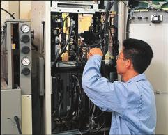


36 36


37 37


.")
38 This solution solves customers' issues and concerns by enabling visualization and analysis that lead to improvements and increase availability at production sites. Utilizing our FA and IT technologies and collaborating with Alliance partners, we reduce the total cost across the entire supply chain and engineeringchain, and support the improvement initiatives and one-step-ahead manufacturing of our customers. Procurement Supply chain FA integrated solutions reduce total cost Product design Engineering chain Process design Production and manufacturing Sale, logistics, and service Operation/Maintenance iq Care iq-works/ezsocket (prevention, predictive maintenance, remote maintenance service) (CAD/simulation linkage) since2003 Supply chain Engineering chain IT system Procurement Production Product Process design design Shop floor ERP SCM MES Simulator SCADA FA-IT Information Interface Drive Quality Data handling MES interface C Controller Sensor Productivity Operation and maintenance CAD/CAM Data primary processing / analysis Edge-computing Sales and distribution Programmable Controller Sustainability Mechatronics Safety Energy-saving Security Overall production information is captured in addition to energy information, enabling the realization of efficient production and energy use (energy savings). 38 Trademarks MODBUS is a registered trademark of Schneider Automation Incorporated. Other company and product names herein are the trademarks and registered trademarks of their respective owners.


39 Automation solutions YOUR SOLUTION PARTNER Low voltage: MCCB, MCB, ACB Medium voltage: VCB, VCC Power monitoring, energy management Mitsubishi Electric offers a wide range of automation equipment from PLCs and HMIs to CNC and EDM machines. Compact and Modular Controllers A NAME TO TRUST Since its beginnings in 1870, some 45 companies use the Mitsubishi name, covering a spectrum of finance, commerce and industry. The Mitsubishi brand name is recognized around the world as a symbol of premium quality. Mitsubishi Electric Corporation is active in space development, transportation, semi-conductors, energy systems, communications and information processing, audio visual equipment and home electronics, building and energy management and automation systems, and has 237 factories and laboratories worldwide in over 121 countries. This is why you can rely on Mitsubishi Electric automation solution - because we know first hand about the need for reliable, efficient, easy-to-use automation and control in our own factories. As one of the world s leading companies with a global turnover of over 4 trillion Yen (over $40 billion), employing over 100,000 people, Mitsubishi Electric has the resource and the commitment to deliver the ultimate in service and support as well as the best products. Inverters, Servos and Motors Visualisation: HMIs Numerical Control (NC) Robots: SCARA, Articulated arm Processing machines: EDM, Lasers, IDS Transformers, Air conditioning, Photovoltaic systems * Not all products are available in all countries. 39
VFD - D700 Series Specifications. The latest low-cost variable speed control solution for centrifugal pumps.
 VFD - D700 Series Specifications The latest low-cost variable speed control solution for centrifugal pumps. Built-in PID Control to maintain pressure, flow, measured value, and much more 125% overload
ROLL TO ROLL FUNCTION MANUAL FR-A (0.4K)-04750(90K)-R2R FR-A (0.4K)-06830(280K)-R2R FR-A (315K)-12120(500K)-R2R
-04750(90K)-R2R FR-A (0.4K)-06830(280K)-R2R FR-A (315K)-12120(500K)-R2R") INVERTER ROLL TO ROLL FUNCTION MANUAL FR-A820-00046(0.4K)-04750(90K)-R2R FR-A840-00023(0.4K)-06830(280K)-R2R FR-A842-07700(315K)-12120(500K)-R2R Roll to Roll Function The FR-A800-R2R inverter has dedicated
INVERTER ROLL TO ROLL FUNCTION MANUAL FR-A820-00046(0.4K)-04750(90K)-R2R FR-A840-00023(0.4K)-06830(280K)-R2R FR-A842-07700(315K)-12120(500K)-R2R Roll to Roll Function The FR-A800-R2R inverter has dedicated
INVERTER FR-D700. Global standard FACTORY AUTOMATION. Pursuing the easy operation. Long life and simple maintenance. Compact and space-saving
 FACTORY AUTOMATION INVERTER FR-D700 Global standard Pursuing the easy operation Long life and simple maintenance Compact and space-saving Supporting various applications Global Player GLOBAL IMPACT OF
Brake resistor can be connected. 150%/1Hz high starting torque by General -purpose magnetic flux vector control. Safety stop function
 Features 1 Highly reliable inverter! Compact yet equipped with highest level of function/performance!! Standard specifications 5 Safety stop function (1) (1) The FR-D700 series is compliant to the EU Machinery
TOSVERT TM VF-nC3 Parameter List
 TOSVERT TM VF-nC Parameter List E658664 - Setting information * Please fill it in if necessary. Item Content Item Content Setting date / person Customer Application Application model Motor manufacturer
AV-300i Specifications. Saftronics Inc. PC10 Product Specifications PC10. Mini Vector AC Drive
 Saftronics Inc. www.saftronics.com TM AV-300i Specifications PC10 Product Specifications PC10 Mini Vector AC Drive 1 (1) T hree-phas e 230V input Drive Hp 1/8 1/4 1/2 1 2 3 5 7.5 10 Nominal applicable
FUJI Inverter. Standard Specifications
 FUJI Inverter o Standard Specifications Norminal applied motor The rated output of a general-purpose motor, stated in kw. That is used as a standard motor. Rated capacity The rating of an output capacity,
S11 Adjustable Speed Drive Engineering Specification
 PART 1 - GENERAL 1.0 Scope This specification shall cover Toshiba S11 AC Variable Frequency Drives, 6 pulse for 3- phase 200-240VAC, 380-500VAC and single phase 200V to 240VAC. 1.1 References A. National
Multi-function, Compact Inverters. 3G3MV Series
 Multi-function, Compact Inverters 3G3MV Series There has been a great demand for inverters with more functions and easier motor control than conventional i OMRON's powerful, compact 3G3MV Series with versat
ADJUSTABLE SPEED DRIVES. AS1 Drive
 ADJUSTABLE SPEED DRIVES AS1 Drive Toshiba s New ASD Product Line The AS1 drive builds on Toshiba s history of supplying powerful, reliable, and versatile drives. We have combined our best drive features
All-rounder with a compact body (Addition of Ethernet communication function models) Easy operability. Extensive option lineup. Ensured maintenance
 Easy operability. Extensive option lineup. Ensured maintenance") INVERTER FR-E700 FACTORY AUTOMATION All-rounder with a compact body (Addition of Ethernet communication function models) Top level of driving performance in compact body Easy operability Extensive option
INVERTER FR-E700 FACTORY AUTOMATION All-rounder with a compact body (Addition of Ethernet communication function models) Top level of driving performance in compact body Easy operability Extensive option
INSTRUCTION MANUAL (BASIC)
") TRANSISTORIZED INVERTER FR-S500 INSTRUCTION MANUAL (BASIC) FR-S540E-0.4K to 3.7K-EC FR-S520SE-0.2K to 1.5K-EC Thank you for choosing this Mitsubishi transistorized inverter. If this is the first time for
TRANSISTORIZED INVERTER FR-S500 INSTRUCTION MANUAL (BASIC) FR-S540E-0.4K to 3.7K-EC FR-S520SE-0.2K to 1.5K-EC Thank you for choosing this Mitsubishi transistorized inverter. If this is the first time for
INVERTER FR-F700PJ INSTRUCTION MANUAL (BASIC) FR-F720PJ-0.4K to 15K (F) FR-F740PJ-0.4K to 15K (F)
 FR-F720PJ-0.4K to 15K (F) FR-F740PJ-0.4K to 15K (F)") INVERTER FR-F700PJ INSTRUCTION MANUAL (BASIC) FR-F720PJ-0.4K to 15K (F) FR-F740PJ-0.4K to 15K (F) Thank you for choosing this Mitsubishi Electric Inverter. This Instruction Manual (Basic) provides handling
INVERTER FR-F700PJ INSTRUCTION MANUAL (BASIC) FR-F720PJ-0.4K to 15K (F) FR-F740PJ-0.4K to 15K (F) Thank you for choosing this Mitsubishi Electric Inverter. This Instruction Manual (Basic) provides handling
General Specifications FECA-TE /2010. Phone: Fax: Web:
 General Specifications FECA-TE-117 06/2010 1. Standard Specifications 1) Three-phase 230V series Output ratings Input ratings Braking Item Specifications Type (FRN C1S-2U) F12 F25 F50 001 002 003 005 Nominal
Before you operate the inverter, the parameters that you must first program are the basic parameters.
 . Main parameters Before you operate the inverter, the parameters that you must first program are the basic parameters..1 Searching for changes using the history function () : History function History
VF-nC1 Adjustable Speed Drive Engineering Specification
 PART 1 - GENERAL 1.0 Scope This specification shall cover Toshiba VF-nC1 AC Variable Frequency Drives, 6 pulse for 100V single-phase 0.1 to 0.75kW, 200V single-phase 0.2 to 2.2kW and 200V threephase 0.1
6.9 Jump frequency - Avoiding frequency resonance
 E581595.9 Jump frequency - Avoiding frequency resonance : Jump frequency : Jumping width Function Resonance due to the natural frequency of the mechanical system can be avoided by jumping the resonant
ADJUSTABLE SPEED DRIVES FS1
 ADJUSTABLE SPEED DRIVES FS1 Now Available With LonWorks BACnet & MetasysN2 FS1 Model FLA & Dimensions (in.)/ Weight (lbs.) VOLTAGE HP MODEL NUMBER FLA FRAME Dimensions (in.) SHIPPING H W D WEIGHT (lbs.)
D SERIES LM16. COMPACT DRIVE V/f and SLV CONTROL. LM16 COMPACT DRIVE V/f and SLV CONTROL
 D SERIES LM16 COMPACT DRIVE V/f and SLV CONTROL LM16 COMPACT DRIVE V/f and SLV CONTROL 1 2 SERIES 1 2 page 4 page 6 Introduction Fields of application 3 page 7 4 page 8 Designation Product offer 5 6 page
Index 2. G Gain settings 4 31 Glossary of terms A 2 Grommets 2 13
 Index A A Group functions 3 9 AC reactors 5 3 Acceleration 1 15, 3 8 characteristic curves 3 26 second function 3 24 two-stage 4 19 Acceleration stop function 3 21 Access levels 3 5, 3 36, 4 25 Access
FR-F K to 55K FR-F K to 55K(-EC) FR-F520-11K to 55K-NA FR-F540-11K to 55K-NA
 FR-F520-11K to 55K-NA FR-F540-11K to 55K-NA") TRANSISTORIZED INVERTER FR-F500 INSTRUCTION MANUAL FR-F520-0.75K to 55K FR-F540-0.75K to 55K(-EC) FR-F520-11K to 55K-NA FR-F540-11K to 55K-NA OUTLINE INSTALLATION AND WIRING OPERATION/ CONTROL Chapter
TRANSISTORIZED INVERTER FR-F500 INSTRUCTION MANUAL FR-F520-0.75K to 55K FR-F540-0.75K to 55K(-EC) FR-F520-11K to 55K-NA FR-F540-11K to 55K-NA OUTLINE INSTALLATION AND WIRING OPERATION/ CONTROL Chapter
ADJUSTABLE SPEED DRIVES VF-S11 Sords Electric
 ADJUSTABLE SPEED DRIVES VF-S11 The Next Generation of Micro Inverters is Here. The S11 provides maximum torque with precise speed control. It features an easy-to-use, quiet and compact design. In addition,
E3 Adjustable Speed Drive Engineering Specification
 E3 Adjustable Speed Drive Engineering Specification PART 1 - GENERAL 1.0 Scope This specification shall cover Toshiba E3 AC Variable Frequency Drives, 6 pulse for 230V and 460V. 1.1 References A. National
INVERTER FR-F700P INSTRUCTION MANUAL (BASIC)
") INVERTER FR-F700P INSTRUCTION MANUAL (BASIC) FR-F720P-0.75K to 110K FR-F740P-0.75K to 560K Thank you for choosing this Mitsubishi Inverter. This Instruction Manual (Basic) is intended for users who "just
INVERTER FR-F700P INSTRUCTION MANUAL (BASIC) FR-F720P-0.75K to 110K FR-F740P-0.75K to 560K Thank you for choosing this Mitsubishi Inverter. This Instruction Manual (Basic) is intended for users who "just
FR-A K - 55K (-NA) FR-A K - 55K (-NA) (-EC)
 FR-A K - 55K (-NA) (-EC)") MITSUBISHI ELECTRIC FR-A 500 Frequency Inverter Instruction Manual FR-A 520 0.4K - 55K (-NA) FR-A 540 0.4K - 55K (-NA) (-EC) Art.No.: 69633 2001 03 02 IB 66790-G MITSUBISHI ELECTRIC INDUSTRIAL AUTOMATION
MITSUBISHI ELECTRIC FR-A 500 Frequency Inverter Instruction Manual FR-A 520 0.4K - 55K (-NA) FR-A 540 0.4K - 55K (-NA) (-EC) Art.No.: 69633 2001 03 02 IB 66790-G MITSUBISHI ELECTRIC INDUSTRIAL AUTOMATION
INSTRUCTION MANUAL (BASIC) FR-F520J-0.4K to 15K(F) FR-F540J-0.4K to 15K(F)
 FR-F520J-0.4K to 15K(F) FR-F540J-0.4K to 15K(F)") TRANSISTORIZED INVERTER FR-F500J INSTRUCTION MANUAL (BASIC) FR-F520J-0.4K to 15K(F) FR-F540J-0.4K to 15K(F) Thank you for choosing this Mitsubishi Transistorized inverter. If this is the first time for
TRANSISTORIZED INVERTER FR-F500J INSTRUCTION MANUAL (BASIC) FR-F520J-0.4K to 15K(F) FR-F540J-0.4K to 15K(F) Thank you for choosing this Mitsubishi Transistorized inverter. If this is the first time for
13. Before making a service call Trip information and remedies
 . Before making a service call Trip information and remedies.1 Trip causes/warnings and remedies When a problem arises, diagnose it in accordance with the following table. If it is found that replacement
FR-D K to 15K FR-D K to 15K FR-D720S-0.1K to 2.2K FR-D710W-0.1K to 0.75K
 INVERTER FR-D700 INSTRUCTION MANUAL (Applied) FR-D720-0.1K to 15K FR-D740-0.4K to 15K FR-D720S-0.1K to 2.2K FR-D710W-0.1K to 0.75K OUTLINE WIRING 1 2 PRECAUTIONS FOR USE OF THE INVERTER 3 PARAMETERS 4
INVERTER FR-A700 INSTRUCTION MANUAL (BASIC) FR-A K to 90K FR-A K to 500K
 FR-A K to 90K FR-A K to 500K") INVERTER FR-A700 INSTRUCTION MANUAL (BASIC) FR-A720-0.4K to 90K FR-A740-0.4K to 500K Thank you for choosing this Mitsubishi Inverter. This Instruction Manual (Basic) is intended for users who "just want
INVERTER FR-A700 INSTRUCTION MANUAL (BASIC) FR-A720-0.4K to 90K FR-A740-0.4K to 500K Thank you for choosing this Mitsubishi Inverter. This Instruction Manual (Basic) is intended for users who "just want
FR-F520J-0.4K to 15K (F) FR-F540J-0.4K to 15K (F)
 FR-F540J-0.4K to 15K (F)") TRANSISTORIZED INVERTER FR-F500J INSTRUCTION MANUAL (Detailed) AIR-CONDITIONING INVERTER FR-F520J-0.4K to 15K (F) FR-F540J-0.4K to 15K (F) WIRING Chapter 1 FUNCTIONS Chapter 2 PROTECTIVE FUNCTIONS Chapter
TRANSISTORIZED INVERTER FR-F500J INSTRUCTION MANUAL (Detailed) AIR-CONDITIONING INVERTER FR-F520J-0.4K to 15K (F) FR-F540J-0.4K to 15K (F) WIRING Chapter 1 FUNCTIONS Chapter 2 PROTECTIVE FUNCTIONS Chapter
D SERIES EM16 IP 20 / NEMA 1 & IP 66 / NEMA 4X COMPACT VECTOR CONTROL DRIVE EM 16 COMPACT VECTOR CONTROL DRIVE
 D SERIES EM16 IP 20 / NEMA 1 & IP 66 / NEMA 4X COMPACT VECTOR CONTROL DRIVE EM 16 COMPACT VECTOR CONTROL DRIVE 1 2 SERIES 1 2 pag. 4 pag. 5 Applications Model identification 3 pag. 5 4 pag. 6 Capacity
ADVANCED AND EVER ADVANCING FR-V200. FR-V200 series
 ADVANCED AND EVER ADVANCING FR-V200 FR-V200 series CONTENTS 1 SPECIFICATIONS 1 1.1 OPERATION PRINCIPLE...1 1.1.1 What is vector control?...1 1.2 Instructions for Using the Inverter...3 1.3 Specification
Power Regenerative Converter, THYFREC CV240S
 Development of New Products Power Regenerative Converter, THYFREC CV240S Harmonic restraint, Power regeneration, 120 conduction, Power factor improvement, Common converter system, Environment compatibility
INVERTER. Model FR-E700. All-rounder. Compact body. Easy for anybody and high performance
 INVERTER Model FR-E7 Remarkable usability Top level driving performance! Compact body All-rounder Easy for anybody and high performance Features 1 Top level driving performance in compact body The inverter
This section is specifically about safety matters
 Thank you for choosing the Mitsubishi Transistorized inverter. This instruction manual gives handling information and precautions for use of this equipment. Incorrect handling might cause an unexpected
SJ700 series High performance with Many useful Functions and, yet User Friendly. WJ200 series Pursuing the Ideal Compact Inverter NEW
 WJ200 series Pursuing the Ideal Compact Inverter NEW SJ700 series High performance with Many useful Functions and, yet User Friendly X200 series Simple, Trip-suppression and Eco-friendly Compact Inverter
System configuration. Ratings 400 V Class three-phase 90 to 800 kw 690 V Class three-phase 90 to 1000 kw SX-D. Frequency inverters.
 ~ ~ SX High performance Vector Control IP54 full range. Compact design & Robustness Built-in Filter according to C3 Class Built-in Fusses (From 200 kw) Safety according EN13849-1 and EN62061 standards
High-performance Vector-type SF-G Series Inverter
 SF-G Series 5.5-160KW Quality and Innovation Industrial Upgrading High-performance ector-type SF-G Series Inverter Superior Performance just for your ISO 14001 BSMI ISO 9001 BSMI 認可登錄 REGISTERED CERT.
This section is specifically about safety matters WARNING CAUTION WARNING
 6 4 ) 5 1 5 6 4 1 -, 1 8-4 6-4. 4 5 # 1 5 6 4 7 + 6 1 ) 7 ), A J = E 5 1 2-1 8-4 6-4. 4 5 # J +! % 4. 4 5 # J! % ) 4. 4 5 # 5 J # 4. 4 5 # 5 J # - + 4 9 1 4 1 / + D = F J A H. 7 + 6 1 5 + D = F J A H 2
Fan and Pump AC Inverter
 Fan and Pump AC Inverter Key Features for Fan and Pump Applications PID and Auto Energy Saving Functions. Input Phase Loss and Output Phase Loss Protection. LCD Keypad can be used to copy parameter settings
INVERTER FR-D700 INSTALLATION GUIDELINE FR-D (SC) to 160(SC)-EC FR-D720S-008(SC) to 100(SC)-EC
 to 160(SC)-EC FR-D720S-008(SC) to 100(SC)-EC") INVERTER FR-D700 INSTALLATION GUIDELINE FR-D740-012(SC) to 160(SC)-EC FR-D720S-008(SC) to 100(SC)-EC Thank you for choosing this Mitsubishi Inverter. Please read through this Installation Guideline and
INVERTER FR-D700 INSTALLATION GUIDELINE FR-D740-012(SC) to 160(SC)-EC FR-D720S-008(SC) to 100(SC)-EC Thank you for choosing this Mitsubishi Inverter. Please read through this Installation Guideline and
Manual Overview...1 2
 GETTING STARTED CHAPTER 1 Contents of this Chapter... Manual Overview.....................................1 2 Overview of this Publication..................................1 2 Who Should Read This Manual...............................1
FR-S520E-0.1K to 3.7K-NA FR-S540E-0.4K to 3.7K-NA FR-S510WE-0.1K to 0.75K-NA
 TRANSISTORIZED INVERTER FR-S500 INSTRUCTION MANUAL (Detailed) SIMPLE INVERTER FR-S520E-0.1K to 3.7K-NA FR-S540E-0.4K to 3.7K-NA FR-S510WE-0.1K to 0.75K-NA WIRING Chapter 1 FUNCTIONS Chapter 2 PROTECTIVE
FR-E K to 7.5K-EC FR-E520S-0.4K to 2.2K-EC
 TRANSISTORIZED INVERTER FR-E500 INSTRUCTION MANUAL HIGH PERFORMANCE & HIGH FUNCTION FR-E540-0.4K to 7.5K-EC FR-E520S-0.4K to 2.2K-EC OUTLINE Chapter 1 INSTALLATION AND WIRING Chapter 2 OPERATION/ CONTROL
ADJUSTABLE SPEED DRIVES. HX7 Series. 18 Pulse. Phone: Fax: Web: -
 ADJUSTABLE SPEED DRIVES HX7 Series 18 Pulse Toshiba HX7 In some industrial applications, users need reliable and efficient adjustable speed drives that do not contribute significant harmonic distortion
G+ Mini Transition Guide. Product Transition Guide P3 Series 2 to G+ Mini
 Transition Guide Product Transition Guide to Rev: Page Intentionally Left Blank Transition Guide September 2008 Page 2 of 24 Table of Contents 1.1 Overview...4 1.2 Drive Replacement Checklist...4 1.3 Ratings
ATV12H018F1 variable speed drive ATV kW hp V - 1ph
 Characteristics variable speed drive ATV12-0.18kW - 0.25hp - 100..120V - 1ph Main Range of product Altivar 12 Product or component type Product destination Product specific application Assembly style Component
ATV12H037F1 variable speed drive ATV kW hp V - 1ph - with heat sink
 Characteristics variable speed drive ATV12-0.37kW - 0.55hp - 100..120V - 1ph - with heat sink Main Range of product Altivar 12 Product or component type Product destination Product specific application
TRANSISTORIZED INVERTER FR-E560 INSTRUCTION MANUAL
 TRANSISTORIZED INVERTER FR-E560 INSTRUCTION MANUAL HIGH PERFORMANCE & HIGH FUNCTION FR-E560-0.75K to 7.5K-NA OUTLINE Chapter 1 INSTALLATION AND WIRING Chapter 2 OPERATION/ CONTROL Chapter 3 PARAMETERS
Variable Frequency Drive / Inverter (0.4 ~ 280kW)
") Variable Frequency Drive / Inverter (0.4 ~ 280kW) & Standard Features Configuration Comparison Comparison Table Enclosure IP00 IP20 NEMA 1 Rating Single phase 0.4 2.2kW 0.4 1.5kW Three phase 0.4 4kW Constant
Variable Frequency Drive / Inverter (0.4 ~ 280kW) & Standard Features Configuration Comparison Comparison Table Enclosure IP00 IP20 NEMA 1 Rating Single phase 0.4 2.2kW 0.4 1.5kW Three phase 0.4 4kW Constant
SX (400V) System configuration
 System configuration") ~ ~ SX (400V) High performance Vector Control IP54 full range. Compact design & Robustness Built-in Filter according to C3 Class Built-in Fusses (From 200 kw) Safety according EN13849-1 and EN62061 standards
~ ~ SX (400V) High performance Vector Control IP54 full range. Compact design & Robustness Built-in Filter according to C3 Class Built-in Fusses (From 200 kw) Safety according EN13849-1 and EN62061 standards
AZ Series. Function Edition. Closed Loop Stepping Motor and Driver Package. Operation. I/O signals. Parameter
 HM-6262 Closed Loop Stepping Motor and Driver Package Operation I/O signals Parameter AZ Series Function Edition Method of control via Modbus RTU (RS-485 communication) Method of control via industrial
SJ100 Series Inverter Quick Reference Guide. Single-phase Input 200V Class Three-phase Input 200V Class Three-phase Input 400V Class
 HITACHI SJ1 Series Inverter Quick Reference Guide Single-phase Input 2V Class Three-phase Input 2V Class Three-phase Input 4V Class Hitachi Industrial Equipment Systems Co., Ltd. Manual No. NB5821XD Dec.
Operating Instructions
 4XH35QB151210 Small General Frequency Converter Operating Instructions 220V 0.75KW 5.5KW 400V 0.75KW 15KW Please read the instruction carefully and understand the contents so that it can be installed and
CHAPTER 8 PARAMETER SUMMARY
 CHAPTER PARAMETER SUMMARY Group 0: System Parameter VFD-V Series 00-00 Identity Code Based on the model type 00-01 Rated Current Display 00-02 Parameter Reset 00-03 00-04 Star-up Display of the Drive Definitions
SX (400 V) System configuration
 System configuration") ~ ~ SX (400 V) High performance Vector Control IP54 full range. Compact design & Robustness Built-in Filter according to C3 Class Built-in Fuses (From 200 kw) Safety according EN13849-1 and EN62061 standards
~ ~ SX (400 V) High performance Vector Control IP54 full range. Compact design & Robustness Built-in Filter according to C3 Class Built-in Fuses (From 200 kw) Safety according EN13849-1 and EN62061 standards
SX (690 V) System configuration
 System configuration") SX (690 V) High performance Vector Control IP54 full range Compact design & Robustness Built-in Filter according to C3 Class Built-in Fuses (From 200 kw) Safety according EN13849-1 and EN62061 standards
SX (690 V) High performance Vector Control IP54 full range Compact design & Robustness Built-in Filter according to C3 Class Built-in Fuses (From 200 kw) Safety according EN13849-1 and EN62061 standards
ATV12HU40M3 variable speed drive ATV12-4kW - 5hp V - 3ph - with heat sink
 Characteristics variable speed drive ATV12-4kW - 5hp - 200..240V - 3ph - with heat sink Main Range of product Altivar 12 Product or component type Product destination Product specific application Assembly
[ 4 ] Using pulse train input (F01 = 12)
![[ 4 ] Using pulse train input (F01 = 12)](/thumbs/90/102625444.jpg "[ 4 ] Using pulse train input (F01 = 12)") [ 4 ] Using pulse train input (F01 = 12) Selecting the pulse train input format (d59) A pulse train in the format selected by the function code d59 can give a frequency command to the inverter. Three types
[ 4 ] Using pulse train input (F01 = 12) Selecting the pulse train input format (d59) A pulse train in the format selected by the function code d59 can give a frequency command to the inverter. Three types
HITACHI. L100-M Series Inverter Quick Reference Guide. Hitachi Industrial Equipment Systems Co., Ltd. Single-phase Input 100V Class
 HITACHI L1-M Series Inverter Quick Reference Guide Single-phase Input 1V Class Hitachi Industrial Equipment Systems Co., Ltd. Manual No. NB5741XD December 23 Caution: Be sure to read the L1 Inverter Manual
General-Purpose AC Servo. MELSERVO-JE Servo amplifier INSTRUCTION MANUAL (TROUBLE SHOOTING)
") General-Purpose AC Servo MELSERVO-JE Servo amplifier INSTRUCTION MANUAL (TROUBLE SHOOTING) F Safety Instructions Please read the instructions carefully before using the equipment. To use the equipment
General-Purpose AC Servo MELSERVO-JE Servo amplifier INSTRUCTION MANUAL (TROUBLE SHOOTING) F Safety Instructions Please read the instructions carefully before using the equipment. To use the equipment
ADJUSTABLE SPEED DRIVES. W7 Series. 18 Pulse
 ADJUSTABLE SPEED DRIVES W7 Series 18 Pulse Meets or Exceeds Your Specifications Standard Specifications Item Voltage Class 460V Maximum HP 60 75 100 125 150 200 250 300 400 500 600 700 800 Drive Rating
ADJUSTABLE SPEED DRIVES. HX7 Series. 18-Pulse
 ADJUSTABLE SPEED DRIVES HX7 Series 18-Pulse Toshiba HX7 In some industrial applications, users need reliable and efficient adjustable speed drives that do not contribute significant harmonic distortion
General-Purpose AC Servo. MELSERVO-JE Servo amplifier INSTRUCTION MANUAL (TROUBLE SHOOTING)
") General-Purpose AC Servo MELSERVO-JE Servo amplifier INSTRUCTION MANUAL (TROUBLE SHOOTING) D Safety Instructions Please read the instructions carefully before using the equipment. To use the equipment
General-Purpose AC Servo MELSERVO-JE Servo amplifier INSTRUCTION MANUAL (TROUBLE SHOOTING) D Safety Instructions Please read the instructions carefully before using the equipment. To use the equipment
INVERTER FR-A800 Plus
 INVERTER FR-A800 Plus FACTORY AUTOMATION The optimum functions for roll to roll applications are added. for Roll to Roll System simplification Wide range of applications Easy startup and adjustment Global
CONTENTS PRODUCT CHECKING AND PARTS IDENTIFICATION... 1 INSTALLATION AND WIRING... 2
 PRESSURE-RESISTANT, EXPLOSION-PROOF MOTOR DRIVING INVERTER FR-B, B3 INSTRUCTION MANUAL (BASIC) FR-B-75 75K(200V), FR-B-75 110K(400V) FR-B3-(N)(H) 40 37K (A700 SPECIFICATIONS) Thank you for choosing this
TECO F510 Inverter. Quick Start Guide. Step 1. Supply & Motor connection
 Quick Start Guide TECO F510 Inverter This guide is to assist you in installing and running the inverter and verify that it is functioning correctly for it s main and basic features. For detailed information
FREQUENCY INVERTER VFR-013 QUICK START GUIDE
 FREQUENCY INVERTER VFR-013 QUICK START GUIDE Inoréa Automation & Industry 9 rue du Lugan 33130 BEGLES www.inorea.com Table of contents 1. PEOPLE SAFETY... 3 2. MATERIAL SAFETY... 3 3. NAME PLATE... 4 a.
AF91 Adjustable Frequency Drives Series B
 Effective: January, 00 Page New Information AF9 Adjustable Model AF9 Description Model AF9 Adjustable Frequency AC Drives are designed to provide adjustable speed control of -phase motors. These microprocessor-based
VFS11 Parameter List for up to CPU version 105
 E65824 VFS Parameter List for up to CPU version 5 Setting Date Customer End user Application Application No/Serial No Inverter s Type-Form Quantity Inverter s Serial No Motor s capacity If user s value
General Purpose Drives
 AC Variable Speed Drive General Purpose Drives Dedicated to Low Power Applications 0.37kW 11kW / 0.5HP 15HP 200 480V 3 Phase Input AC Variable Speed Drive 0.37kW 11kW / 0.5HP 15HP 110 480V Single & 3 Phase
ATV12HU22M2. Main. Range of product Altivar 12. Component name Quantity per set Set of 1. Built-in fan. Motor power hp Communication port protocol
 Product datasheet Characteristics ATV12HU22M2 Complementary Main Range of product Altivar 12 Product or component type Product destination Product specific application Assembly style Component name Variable
P-SERIES VFD 1-40HP (200~230VAC), 1-400HP (380~480VAC),3Ø Dual Rated for Constant & Variable Torque Integrated PID Control
, 1-400HP (380~480VAC),3Ø Dual Rated for Constant & Variable Torque Integrated PID Control") P-SERIES VFD 1-40HP (200~230VAC), 1-400HP (380~480VAC),3Ø Dual Rated for Constant & Variable Torque Integrated PID Control NEW FIRMWARE MAKES SETUP A SNAP Application based commissioning allows parameters
P-SERIES VFD 1-40HP (200~230VAC), 1-400HP (380~480VAC),3Ø Dual Rated for Constant & Variable Torque Integrated PID Control NEW FIRMWARE MAKES SETUP A SNAP Application based commissioning allows parameters
HPVFP High Performance Full Function Vector Frequency Inverter
 Advanced User Manual HPVFP High Performance Full Function Vector Frequency Inverter HP VER 1.00 1. HPVFP Parameter Set Overview...3 1.1. About this section...3 1.2. Parameter Structure Overview...3 1.3.
The new Yaskawa Varispeed G7 Inverter
 The new Yaskawa Varispeed G7 Inverter Unique new 3-level PWM flux vector Constant or variable torque applications control method 0.4 kw to 300 kw power range Exceptional low speed/high torque control Quick
WJ200 series Pursuing the Ideal Compact Inverter
 WJ200 series Pursuing the Ideal Compact Inverter X200 series Simple, Trip-suppression and Eco-friendly Compact Inverter NE-S1 series Economical Inverter with Simple Operation SJ700B series Inverter designed
Inverter Drive /Vector Drive Motors & Controls
 H2 Inverter/ Encoderless Vector Inverter Drive /Vector Drive & Controls 3/4 thru 50 180-264 VAC 3 Phase - 50/60 Hz 3/4 thru 60 340-528 VAC 3 Phase - 50/60 Hz 3/4 thru 60 515-660 VAC 3 Phase - 60 Hz HVAC
α α Retry count clear Alarm reset Active End of retry S-curve time during accelerati on H04: (Count) setting S curve time during decelerati on
 setting S curve time during decelerati on") Upon success of retry Alarm Occurrence Disappearance Time S-curve acceleration/deceleration To reduce the shock of the mechanical system, the change in the output frequency is made smooth when the frequency
Upon success of retry Alarm Occurrence Disappearance Time S-curve acceleration/deceleration To reduce the shock of the mechanical system, the change in the output frequency is made smooth when the frequency
Caution. Three-phase 400V series FRN0.4C1S-4A FRN0.75C1S-4A FRN1.5C1S-4A FRN2.2C1S-4A FRN3.7C1S-4A
 Variation Caution The contents of this catalog are provided to help you select the product model that is best for you. Before actual use, be sure to read the User s Manual thoroughly to assure correct
ATV12H037F1 variable speed drive ATV kW hp V - 1ph - with heat sink
 Characteristics variable speed drive ATV12-0.37kW - 0.55hp - 100..120V - 1ph - with heat sink Product availability : Stock - Normally stocked in distribution facility Price* : 191.76 USD Main Range of
MR-J4-DU_B_-LL SERVO AMPLIFIER INSTRUCTION MANUAL
 General-Purpose AC Servo SSCNET /H Interface AC Servo for Pressure Control MODEL (SERVO AMPLIFIER) MR-J4-_B_-LL MODEL (DRIVE UNIT) MR-J4-DU_B_-LL SERVO AMPLIFIER INSTRUCTION MANUAL Safety Instructions
GS1 Parameter Summary Detailed Parameter Listings...4 9
 CHAPTER AC DRIVE 4 PARAMETERS Contents of this Chapter... GS1 Parameter Summary...............................4 2 Detailed Parameter Listings..............................4 9 Motor Parameters.........................................4
SYSDRIVE 3G3HV Inverter Models The following 200- and 400-V class 3G3HV Inverter models are available.
 Function The 3G3HV High-capacity General-purpose Inverter is an easy-to-use inverter that has advanced features, such as PID control and energy-saving operations. SYSDRIVE 3G3HV Inverter Models The following
INVERTER. Model FR-F800. Enhanced Next-Generation Energy-Saving Inverter F800 F800
 INVERTER Model FR-F800 Enhanced Next-Generation Energy-Saving Inverter F800 F800 1 ENERGY SAVING Energy Saving with Inverters The consumed power of a variable-torque load, such as fans, pumps, and blowers,
High Performance Compact Inverter User's Manual
 High Performance Compact Inverter User's Manual Copyright 2007 Fuji Electric FA Components & Systems Co., Ltd. All rights reserved. No part of this publication may be reproduced or copied without prior
INDEX. i 1. B Braking Resistor Dimensions: A 24 Braking Resistors: A 20 Braking Units: A 20. DURAPULSE AC Drive User Manual
 INDEX A AC Drive Cover: 1 6 Dimensions: 2 4 External Parts and Labels: 1 6 Heat Sink Fins: 1 6 Input Mode Switch (Sink/Source): 1 6 Introduction to DuraPulse GS3 AC drive: 1 3 Keypad: 1 6 Model Number
CHAPTER AC DRIVE PARAMETERS. In This Chapter...
 CHAPTER AC DRIVE 4 PARAMETERS In This Chapter... GS2 Parameter Summary....................4 2 Detailed Parameter Listings.................4 11 Motor Parameters........................4 11 Ramp Parameters.........................4
Cat. No. I528-E1-2 USER S MANUAL SYSDRIVE 3G3JV. Compact Simplified Inverters
 Cat. No. I528-E1-2 USER S MANUAL SYSDRIVE 3G3JV Compact Simplified Inverters Thank you for choosing this SYSDRIVE 3G3JV-series product. Proper use and handling of the product will ensure proper product
Phoenix DX Clean Power (18 Pulse) AC Drive
 AC Drive") PHOENIX DX Phoenix DX Clean Power (18 Pulse) AC Drive Poor power quality can be costly. Nonlinear loads, including AC Drives, introduce undesirable harmonic currents into the power system that can damage
PHOENIX DX Phoenix DX Clean Power (18 Pulse) AC Drive Poor power quality can be costly. Nonlinear loads, including AC Drives, introduce undesirable harmonic currents into the power system that can damage
This operation manual is intended for users with basic knowledge of electricity and electric devices.
 This operation manual is intended for users with basic knowledge of electricity and electric devices. Safety Information Safety Information Read and follow all safety instructions in this manual precisely
SECTION 16483D ADJUSTABLE FREQUENCY DRIVE - MICRODRIVE (MVX <10-HP)
") ADJUSTABLE FREQUENCY DRIVE - MICRODRIVE (MVX
ADJUSTABLE FREQUENCY DRIVE - MICRODRIVE (MVX
FR-E KNC to 15KNC FR-E KNC to 15KNC FR-E720S-0.1KNC to 2.2KNC
 INVERTER FR-E700 INSTRUCTION MANUAL (Applied) CC-Link communication function FR-E720-0.1KNC to 15KNC FR-E740-0.4KNC to 15KNC FR-E720S-0.1KNC to 2.2KNC OUTLINE WIRING 1 2 PRECAUTIONS FOR USE OF THE INVERTER
Warning!! 2. The drive contains high voltage that can cause electric shock resulting in personal injury or loss of life.
 ! Warning!! 1. Please read this manual completely before installing the drive. 2. The drive contains high voltage that can cause electric shock resulting in personal injury or loss of life. 3. Be sure
Rexroth Frequency Converter Fe 0.75 kw to 7.5 kw / 400 VAC
 Electric Drives and Controls Hydraulics Linear Motion and Assembly Technologies Pneumatics Rexroth Frequency Converter Fe 0.75 kw to 7.5 kw / 400 VAC Simple, scalable and economical Service Bosch Rexroth
Series Concepts. Ideal functions to meet various needs. New, compact design. Simple operation. Flexible through optionals
 MEH441a Series Concepts Ideal functions to meet various needs New, compact design Simple operation Flexible through optionals A broad range of model variations Actual size Global products The FRENIC-Mini
INVERTER FR-D700 INSTALLATION GUIDELINE FR-D to 160-EC FR-D720S-008 to 100-EC
 INVERTER FR-D700 INSTALLATION GUIDELINE FR-D740-012 to 160-EC FR-D720S-008 to 100-EC Thank you for choosing this Mitsubishi Inverter. Please read through this Installation Guideline and a CD-ROM enclosed
SAFETY INSTRUCTIONS WARNING
 Important User Information Thank you for purchasing LS Variable Frequency Drives! SAFETY INSTRUCTIONS Always follow safety instructions to prevent accidents and potential hazards from occurring. In this
MR-C Servo SERVOMOTORS & AMPLIFIERS. Step Up to Servo Performance
 MR-C Servo SERVOMOTORS & AMPLIFIERS Step Up to Servo Performance Small, Easy-to-Use, High- Performance. An Extraordinarily Compact, Intelligent Servo. The MR-C brushless servo, in a handy super-compact
MITSUBISHI ELECTRIC INVERTER FR-D700 INSTALLATION GUIDELINE FR-D720S-008 to 100-EC FR-D to 160-EC
 MITSUBISHI ELECTRIC INVERTER FR-D700 INSTALLATION GUIDELINE FR-D720S-008 to 100-EC FR-D740-012 to 160-EC Thank you for choosing this Mitsubishi Inverter. Please read through this Installation Guideline
General-Purpose AC Servo. MELSERVO-JE Servo amplifier INSTRUCTION MANUAL (TROUBLE SHOOTING)
") General-Purpose AC Servo MELSERVO-JE Servo amplifier INSTRUCTION MANUAL (TROUBLE SHOOTING) B Safety Instructions Please read the instructions carefully before using the equipment. To use the equipment
General-Purpose AC Servo MELSERVO-JE Servo amplifier INSTRUCTION MANUAL (TROUBLE SHOOTING) B Safety Instructions Please read the instructions carefully before using the equipment. To use the equipment