Banded Millimeter Wave Network Analysis TECHNICAL OVERVIEW
|
|
|
- Gervase Mark O’Connor’
- 5 years ago
- Views:
Transcription

1 Banded Millimeter Wave Network Analysis TECHNICAL OVERVIEW
2 Banded Measurement Solutions to 1.5 THz Keysight offers a variety of banded millimeter-wave solutions that enable the PNA/ PNA-X network analyzers to make S-parameter measurements up 1.5 THz. These solutions are easily configurable with frequency extenders from OML Inc and Virginia Diodes Inc. Supported solutions through Keysight may be configured with or without a test set controller, depending on the measurements required and the frequency extenders being used. There is also an affordable E-band solution with PXI-VNA and VDI frequency extenders. More information is given at the end of this technical overview. Supported Measurement Capability The following table is a summary of some of the measurement capability that is available using the banded configurations. Application type Test set controller support Direct control support S-parameters Yes Yes True-mode measurements Yes No Time domain Yes Yes Enhanced Time Domain No No Power measurements 3 Yes Yes Power sweep 3 (single frequency) Yes Yes Power spectrum Yes No Pulse 3 Yes Yes Mixers Yes No Material measurements Yes Yes Antenna measurements Yes Yes On-wafer measurements Yes Yes Inter-modulation distortion Yes 4 No Spectrum Analysis Yes No Noise figure No No Source phase control No No Automatic Fixture Removal Yes 5 No NVNA/X-Parameters No No Differential IQ No No 1. The above is not a complete list of capabilities but is what has been verified to date using the banded solution. 2. Please work with your local Keysight Sales representative for measurements not listed above. 3. Note for PNA-X models that work below 67 GHz pulse and RF power leveling is available with the rear panel switched outputs and requires the combiner option. For the PNA models that work below 67 GHz it is required that the front panel connection be used for pulse and power level support. 4. Inter-modulation distortion (Option 087 or S93087A) is required when using OML IMD module and PNA/PNA-X with Windows Band pass mode only Page 2


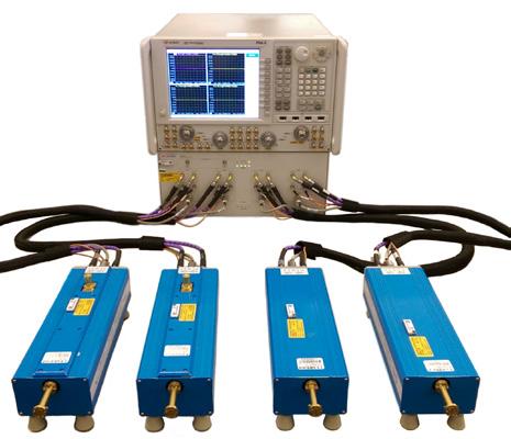
3 Test Set Controller Solutions Key Features Uses the N5261/2A and the N5292A test set controller to connect banded waveguide frequency extenders to the PNA/PNA-X. The N5261A/62A/92A test set controller enables to configure a 2-port millimeterwave system with a single source PNA. - The N5262A/92A test set controller enables to configure a 4-port millimeter-wave system with a dual source PNA. The N5261/62A are designed to provide DC supply to the OML frequency extenders. The built-in millimeter wave dialog allows users to easily switch between different waveguide band frequency extenders connected to the test set controllers. Supports the connection of VDI frequency extenders that cover waveguide bands from 26.5 GHz to 1.5 THz. Supports the connection of OML frequency extenders that cover waveguide bands from 50 GHz to 500 GHz. The 4-port N5262A and the N5292A Option 400 test controllers support differential and converter measurements using the VDI and OML frequency converters. Keysight test set controller with the PNA/PNA-X can be used to calibrate and control the power at the waveguide. Page 3

4 Test Set Controller Solutions Test set controller based solutions performance The test set controller based solutions offer not only the highest frequency coverage up to 1.5 THz but have also shown the best dynamic range in the industry. The following is an example of a WR2.2 frequency extender dynamic range using a PNA/PNA-X network analyzer, and a N5262A test set controller with a typical performance of 100 db in a 10 Hz IFBW. 150 Dynamic Range of WR2.2 10Hz IF BW, 1001pts, 10 Sweep Avg Dynamic range, db Frequency, GHz Figure 9. Dynamic range of a 325 to 500 GHz WR 2.20 VDI frequency extender Ease-of-use The banded millimeter-wave system uses built-in firmware, allowing you to leverage the built in software features of the PNA and PNA-X Series network analyzers. Regardless of the frequency range of your measurements, you can manually control the instrument from the front panel or use a mouse to access the simple pull-down menus. In addition, you can utilize Cal Wizard to guide you step-by-step through the most complicated of calibrations. The banded millimeter-wave system can easily be configured using the dialogue box shown in Figure 10. Multiple system configurations can be added to the list, but only one is active at a time. Creating a banded configuration is easy, simply enter the start and stop frequencies and the multipliers for RF and LO frequency ranges (the values are located on the test head modules). Once a configuration has been added to the list, simply highlight the setup of choice and then click Activate Selected Config to apply. Figure 10. On-screen dialog to configure a banded millimeter-wave setup Page 4

5 Test Set Controller Solutions A number of different configurations can be setup for different frequency bands. In addition, for the N5261A and N5262A there is the added capability to turn on and off the test set controller ALC for pulse measurements. Also available, is the ability to enable mixer sweep for scalar mixer measurements. This interface allows for ease of switching from one configuration to the next without restarting the PNA/PNA-X or reconfiguration of connections. In addition, an extensive, context-sensitive Help system thoroughly explains all of the PNA and PNA-X features. In any dialog box, simply click Help to see a detailed explanation of the feature you are using. Programming examples in both SCPI and COM are also included. Test set controller based solution block diagram (N5262A) Page 5


6 Test Set Controller Solutions Test set controller based solution block diagram (N5292A) Page 6

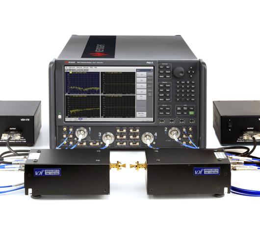
7 Direct Connect Solutions These solutions do not require a millimeter-wave test set controller as they connect directly to the front panel of a dual source PNA or PNA-X. Both VDI and OML frequency extenders are supported with this configuration. Here is an example of a set of VDI modules that are directly connected to a dual source PNA. Key Features This configuration does not require a test set controller. Requires a dual source PNA/PNA-X network analyzer with configurable test set option. It takes advantage of the FOM mode (Option 080), that allows the dual source to provide separate RF and LO signals for the extenders. Supports full 2-Port S-parameter measurements within a waveguide. The direct connection supports power calibration and power sweep. Allows for the use of a higher IF frequency for test and reference signals. Can be driven with either a 26.5, 43.5, 50, or 67 GHz PNA/PNA-X. A downloadable macro is available from Keysight which simplifies the setup of the frequency offset mode. Provides the best dynamic range performance. The direct connection configuration is currently supported using the frequency offset mode of the PNA/PNA-X and requires at least two sources to be able to do complete 2-port S-parameter measurements. The RF signal for the frequency extenders are supplied via the PNA/PNA-X port 1 and port 2 while the LO is supplied with the second source that drives the PNA/PNA-X ports 3 and 4. With this hardware configuration, the frequency offset mode can be used to set the RF source to sweep the frequency range of the waveguide band while the LO sweeps the mixers in the extenders to produce the IF signals required to make S-parameter measurements. Page 7

8 Direct Connect Solutions Key Performance Calibration technology is built into the PNA/PNA-X that enables the most accurate measurements. The following are a few of the performance characteristics of the system. Figure 11 is a demonstration of the achievable stability of this system; it shows the vector magnitude stability of a 500 to 750 GHz solution over a period of 24 hours under typical laboratory conditions of 25 C. Figure 11. Typical drift performance of the PNA/PNA-X solution at 500 to 750 GHz with Virginia Diodes frequency extenders Notice the excellent performance of less than 0.15 db of both the short terminated ports relative to memory over a period of 24 hours. The key performance characteristic is the excellent dynamic range as illustrated by the 500 to 750 GHz. Page 8
9 Direct Connect Solutions Figure 12. WR1.5 Dynamic range measurements VDI frequency extenders with a PNA-X This solution provides unsurpassed dynamic range performance as shown in the Figure 12 plot of a 500 to 750 GHz dynamic range measurement using a direct connection of VDI extenders to a PNA/PNA-X. Note the typical performance is around 100 db of dynamic range. Page 9

10 Direct Connect Solutions Direct connect solution block diagram This configuration of the PNA/PNA-X with frequency extenders offers the ability to directly connect frequency extenders to a 4-port PNA/PNA-X or a 2-port PNA-X with a second source. This enables vector network analysis measurements up to 1.5 THz. Page 10
11 Banded Solution Configuration Configuration of a banded solution is similar to configuration of a single sweep solution using separate components. With the support of several frequency extenders and vector network analyzer options, the banded solutions, offer industry leading flexibility and extensibility for measurements to 1.5 THz. To configure hardware for a particular solution select the following components: 1. PNA or PNA-X network analyzer configured to support either a test set controller or direct connection of the frequency extenders or 4-port millimeter test set controller, not required for direct connection. See page 13 for Supported measurement capability. 3. Frequency extenders for the frequency coverage required, see pages 12 to 14 for VDI extenders and pages 16 to 18 for OML extenders (Refer to Configuring a module on page 20) 4. Calibration kit for the frequency coverage required, see pages 14 (VDI Cal kits) and page 18 (OML cal kits) Supported PNA and PNA-X configurations for banded waveguide Product model and description Minimum option required for N5292A test set controller connection Minimum option required for N5261A/2A test set controller connection N522xB 2-port PNA Network Analyzer options 201 or 21x and 020 options 2xx and 020 Unsupported Minimum option required for direct connection N522xB 4-port PNA Network Analyzer options 401 or 41x and 020 options 4xx and 020 Option 401 or 41x and S93080A N524xB 2-port PNA-X Network Analyzer options 2xx and 020 options 2xx and 020 Option 22x and S93080A N524xB 4-port PNA-X Network Analyzer options 4xx and 020 options 4xx and 020 Option 4xx and S93080A N522xA 2-port PNA Network Analyzer Unsupported options 2xx and 020 Unsupported N522xA 4-port PNA Network Analyzer Unsupported options 4xx and 020 Options 401 or 41x and 080 N524xA 2-port PNA-X Network Analyzer Unsupported options 200 and 020 Options 200, 219, 224 and 080 N524xA 4-port PNA-X Network Analyzer Unsupported options 400 and 020 Options 400, 419 and 080 Millimeter-wave test set controllers for banded configuration N5292A Port millimeter-wave test set controller 1 N5292A-222 Interconnect Kit for 2 Port Test Set and 2 Port VNA with 3.5 mm Ports N5292A-224 Interconnect Kit for 2 Port Test Set and 2 Port VNA with 2.4 mm Ports N5292A- 242 Interconnect Kit for 2 Port Test Set and 4 Port VNA with 3.5 mm Ports N5292A-244 Interconnect Kit for 2 Port Test Set and 4 Port VNA with 2.4 mm Ports N5290A304 Cable Adapter for OML/ VDI Frequency Extenders N5292A Port millimeter-wave test set controller 1 N5292A-422 Interconnect Kit for 4 Port Test Set and 2 Port VNA with 3.5 mm Ports N5292A-424 Interconnect Kit for 4 Port Test Set and 2 Port VNA with 2.4 mm Ports N5292A- 442 Interconnect Kit for 4 Port Test Set and 4 Port VNA with 3.5 mm Ports N5292A-444 Interconnect Kit for 4 Port Test Set and 4 Port VNA with 2.4 mm Ports N5290A304 Cable Adapter for OML/ VDI Frequency Extenders 1. The N5290A304 interface cable is required for each OML/VDI module for both the 2- and 4-port N5292A. Page 11
12 Banded Solution Configuration N5261A 2-port millimeter-wave test set controller for PNA/PNA-X based configuration N5261A-102 A set of cables for 3.5 mm connection to a 2-port N5222A or N5242A N5261A-104 A set of cables for 3.5 mm connection to a 4-port N5222A or N5242A N5261A-106 A set of cables for 2.4 mm connection to a 2-port N5224A/N5225A or N5244A/N5245A N5261A-108 A set of cables for 2.4 mm connection to a 4-port N5224A/N5225A or N5244A/N5245A N5261A-112 A set of cables for 1.85 mm connection to a 2-port N5227A or N5247A N5262A 4-port millimeter wave test set controller for PNA/PNA-X based configuration N5262A-104 N5262A-108 N5262A-114 A set of cables for 3.5 mm connection to a 4-port N5222A or N5242A A set of cables for 2.4 mm connection to a 4-port N5224A/N5225A or N5244A/N5245A A set of cables for 1.85 mm connection to a 4-port N5227A or N5247A For the N5261A and N5262A, several cable options exist for connecting OML T/R frequency extenders, please refer to the option description section for details, page 18. A 2-Port PNA/PNA-X will only support 2-port banded measurements when used with a N5262A 4-port millimeter controller. Please refer to the Millimeter Wave Network Analyzer (N5290A/91A) Configuration Guide, literature number: EN, for more details and required interconnect options to connect the N5292A to the PNA and PNA-X network analyzers. Module types Transmission/reflection modules TxRx modules (VDI) or Transmission/reflection modules (OML) that have both a receiver and a transmitter and can perform both transmission and reflection measurements Transmitter modules TxRef modules (VDI) that have a transmitter source and a reference output Receiver-only modules Rx modules (VDI) or T modules (OML) that only have a receiver, and require a transmission/reflection module or a TxRef module to perform transmission measurements. Rx modules cannot perform reflection measurements. Page 12
13 Millimeter-wave modules Several modules are available and other special options may be configured on request. Select the appropriate quantity of modules required for the measurement set up. To request a specially configured test module contact your local Keysight sales representative. Transmission/reflection mini-modules (Virginia Diodes Inc.) Waveguide flange Frequency GHz Standard transmission reflection modules WR to 40 N5262BW28-STD N5262BW28-STD WR19 40 to 60 N5262BW19-STD N5262BW WR to 77 N5262BW15-STD N5262BW WR12 1,2 55 to 95 N5262BW12-STD N5262BW WR10 1,2 67 to 115 N5262BW10-STD N5262BW WR to 140 N5262BW08-STD N5262BW WR to 170 N5262BW06-STD N5262BW WR to 220 N5262BW05-STD N5262BW WR to 260 N5262BW04-STD N5262BW WR to 330 N5262BW03-STD N5262BW WR to 400 N5262BW2B-STD N5262BW2B-001 WR to 500 N5262BW02-STD N5262BW Transmission reflection modules with 0 to 30 db micrometer driven attenuator A power supply is included with each module ordered. All modules are compatible with PNA/PNA-X or test set controller and have cable options for direct connection or test set connections. Modules include a selectable cable set option, and the input power of modules is determined by the cable set option. Option 120: 1.2 m cable set. RF/LO power input requirement is +10 dbm at the module input. Recommend for use with the test set Option 500: 5 m cable set. RF/LO power input requirement is +2 dbm at the module input. Recommended for direct connect. Option 500 can also work with 1.2m cables, which can be purchased as the N5262AKCBLs separately. It requires the module input power to be lowered to +2dBm. 1. TxRx Mini VNAX modules with extended frequency range. 2. These special options are also available. N5262BW10-DS0 Dual source for IMD, WR10+, GHz N5262BW10-DS1 Dual source for IMD with 0-30 db attenuator WR10+, GHz N5262BW10-SE0 Export control, TPP<0dBm, Maximum Frequency <110GHz N5262BW10-SE1 Export control TPP<0dBm, Maximum Frequency <110GHz with 0-30 db attenuator N5262BW12-DS0 Dual Source module for IMD WR GHz N5262BW12-DS1 Dual Source for IMD with 0-30 db attenuator WR GHz N5262BW12-SE0 Export control, 60-90GHz <15dBm N5262BW12-SE1 Export control, 60-90GHz <15dBm with 0-30 db attenuator Page 13
14 Banded Solution Configuration Transmission/reflection modules (Virginia Diodes Inc.) Waveguide flange Frequency GHz Standard transmission/reflection modules WR to 750 N5256AW N5256AW WR to 1100 N5262AW No Attenuator Option WR to 1500 N5262AW No Attenuator Option Each product number includes a single frequency extender that supports all PNA/PNA-X and test sets. A power supply is included with each module ordered. For full 2-Port S-parameter measurements order quantity 2 of the Tx/Rx modules listed above. Transmission/reflection modules with 25 db mechanical attenuator Transmitter and reference receiver modules (Virginia Diodes Inc.) Waveguide flange Frequency GHz Transmitter module WR to 77 N5262BT15-STD N5262BT WR to 95 N5262BT12-STD N5262BT WR to 115 N5262BT10-STD N5262BT WR to 330 N5262BT03-STD N5262BT WR to 500 N5262BT02-STD N5262BT We may be able to provide the modules for some other bands. Please check with your Keysight sales representative. Transmitter/reference receiver modules with 0 to 30 db attenuator Receiver mini-modules (Virginia Diodes Inc.) Waveguide flange Frequency GHz High sensitivity receive only module with external fixed attenuator WR to 77 N5262BR WR to 95 N5262BR WR to 115 N5262BR WR to 140 N5262BR WR to 170 N5262BR WR to 220 N5262BR WR to 260 N5262BR WR to 330 N5262BR WR to 400 N5262BR2B-001 WR to 500 N5262BR A power supply is included with each module ordered. All modules are compatible with PNA/PNA-X or test set controller and have cable options for direct connection or test set connections. Modules include a selectable cable set option, and the input power of modules is determined by the cable set option. Option 120: 1.2 m cable set. RF/LO power input requirement is +10 dbm at the module input. Recommend for use with the test set Option 500: 5 m cable set. RF/LO power input requirement is +2 dbm at the module input. Recommended for direct connect. Option 500 can also work with 1.2m cables, which can be purchased as the N5262AKCBLs separately. It requires the module input power to be lowered to +2dBm. 1. TxRx Mini VNAX modules with extended frequency range. For more information on VDI mini modules, please refer to the product note, N5262BWxx, N5262BTxx, and N5262BRxx Mini VNA Extension Modules, N Page 14
15 Banded Solution Configuration Receiver modules (Virginia Diodes Inc.) Waveguide flange Frequency GHz Standard receiver only modules WR to 750 N5256AR N5256AR WR to 1100 N5262AR Not Available WR to 1500 N5262AR N5262AR High sensitivity receive only module with external fixed attenuator Modules include a selectable option for use with a 1.2 m cable set (Option 120) or a 5m cable set (Option 500). A power supply is included with each module ordered. All modules are compatible with PNA/PNA-X or test set controller and have cable options for direct connection or test set connections. Dimensions for waveguide transmission/reflection modules (Virginia Diodes Inc.) Module Width Length Height Standard 5.0 inches inches including waveguide, WR1.5 to WR inches including waveguide WR inches (feet adjust inches) Mini-modules 3.0 inches 8.5 inches, N5262BWxx and N5262BTxx 1.5 inches (feet adjust inches) 3.0 inches 3.75 inches, N5262BRxx 1.5 inches (feet adjust inches) Calibration kits (Virginia Diodes Inc.) Waveguide flange Frequency GHz Calibration kit WR to 40 N5260AC28 WR19 40 to 60 N5262AC19 WR15 50 to 75 N5262AC15 WR12 60 to 90 N5262AC12 WR10 75 to 110 N5262AC10 WR to 140 N5262AC08 WR to 170 N5262AC06 WR to 220 N5262AC05 WR to 260 N5262AC04 WR to 325 N5262AC03 WR to 400 N5262AC28 WR to 500 N5262AC02 WR to 750 N5260AC01 WR to 1100 N5262AC01 WR to 1500 N5262AC065 Page 15
16 Banded Solution Configuration Cable Options (Virginia Diodes Inc.) Cable option Description N5262AWCBL-N01 Cables not included for Option 700 or 701 Tx/Rx modules which are designed for use with 1.2m cable set. N5262AWCBL-N05 Cables not included for Option 700 or 701 Tx/Rx modules which are designed for use with 5m cable set. N5262AWCBL m cable set for Option 700 or 701 Tx/Rx modules, for direct connect to > 43.5 GHz PNA/PNA-X. Includes an additional 50 GHz RF cable for high frequency operation of the Tx/Rx module. N5262AWCBL-705 5m cable set for Option 700 or 701 Tx /Rx modules, for connection to a N5261/62A test set. N5262AWCBL m cable set for Option 700 or 701 Tx/Rx modules, for direct connects to 26.5 GHz PNA / PNA-X. N5262AWCBL-205 5m cable set for Option 700 or 701 Tx/Rx modules, for direct connects to 26.5 GHz PNA / PNA-X. N5262AWCBL m cables set for Option 700 or 701 Tx/Rx modules, for direct connect to > 43.5 GHz PNA/PNA-X. Does not include an additional 50 GHz RF cable for high frequency operation of the Tx/Rx modules. N5262AWCBL-405 5m cables set for Option 700 or 701 Tx/Rx modules, for direct connect to > 43.5 GHz PNA/PNA-X. Does not include an additional 50 GHz RF cable for high frequency operation of the Tx/Rx modules. N5262AWCBL m cable set for Option 700 or 701 Tx /Rx modules, for connecting to N5261/62A test set. N5262ARCBL-N01 Cables not included for Option 700 or 701 Rx only modules which are designed for use with 1.2m cable set. N5262ARCBL-N05 Cables not included for Option 700 or 701 Rx only modules which are designed for use with 5m cable set. N5262ARCBL m cable set for Option 700 or 701 Rx only modules, for direct connect to > 43.5 GHz PNA/PNA-X. Includes an additional 50 GHz RF cable for high frequency operation. N5262ARCBL-705 5m cable set for Option 700 or 701 Rx only modules, for connection to a N5261/62A test set. N5262ARCBL m cable set for Option 700 or 701 Rx only modules, for direct connect to 26.5 GHz PNA/PNA-X. N5262ARCBL-205 5m cable set for Option 700 or 701 Rx only modules, for direct connect to 26.5 GHz PNA/PNA-X. N5262ARCBL m cable set for Option 700 or 701 Rx only modules, for direct connect to > 43.5 GHz PNA/PNA-X. N5262ARCBL-405 5m cable set for Option 700 or 701 Rx only modules, for direct connection to > 43.5 GHz PNA/PNA-X. N5262ARCBL m cable set for Option 700 or 701 Rx modules, for connecting to N5261/62A test set. Note: Adapters may be purchased separately to allow for connection to both PNA/PNA-X front panel and N5261A/62A test sets. Page 16
17 Banded Solution Configuration The single and dual channel receiver modules are used for antenna applications or for 1-port single path S-parameter measurements. For more information, please refer to the user s guide, N5256/7/8A/B Millimeter-wave Module, N Transmission/reflection modules (OML Inc.) Waveguide flange Frequency GHz Standard transmission/ reflection modules Transmission/reflection modules with 25 db mechanical attenuator Transmission/reflection modules with 15 db LO and RF amplifier 1 Transmission/reflection modules with adjustable attenuator and 15 db gain LO and RF amplifier WR to 75 N5256BW15-STD 3 N5256BW N5256BW N5256BW WR to 90 N5256BW12-STD 3 N5256BW N5256BW N5256BW WR10 75 to 110 N5256AW10-STD 3 N5256AW N5256AW N5256AW WR08 90 to 140 N5256AW08-STD N5256AW N5256AW N5256AW WR to 170 N5256AW06-STD N5256AW N5256AW N5256AW WR to 220 N5256AW05-STD N5256AW N5256AW N5256AW WR to 325 N5256AW03-STD N5256AW N5256AW N5256AW WR to 500 N5256AW02-STD Not available N5256AW Not available Extended WR to 94 N5256BX12-STD N5256AX N5256AX Not available Extended WR10 67 to 110 N5256AX10-STD N5256AX Not available Not available - A power supply is included with each module ordered. - The modules with the RF/LO amplifiers are for antenna applications that include a cable loss of 15 dbm to the module from the port of the test set controller being used. Do not connect these directly to the test set controller port with the standard 48 inch cable, use a 15 db pad if needed. 1. BW15/12 and AW15/12 models cannot be mixed in a system. (BW and AW have different LO multipliers.) 2. BX12 and AX12 model cannot be mixed in a system. (BX and AX have different LO multipliers.) 3. N5256AW12/15 and N5256AX12 are non-rohs versions. IMD transmission/reflection modules (OML Inc.) Waveguide flange Frequency GHz IMD module product number WR15 50 to 75 N5256AW15-IMD 1 WR12 60 to 90 N5256AW12-IMD 1 Extended WR12 56 to 94 N5256AX12-IMD 1 WR10 75 to 110 N5256AW10-IMD Extended WR10 67 to 110 N5256AX10-IMD - Recommend to use with the S93087A IMD measurement application software for IMD measurements with these modules. - The IMD modules require the use of a N5292A-400 or N5262A 4-port controller. 1. N5256AW12/15 and N5256AX12 are non-rohs versions. Page 17
18 Banded Solution Configuration Single-channel receiver-only modules (OML Inc.) Waveguide flange Frequency GHz Standard Single-channel receiver-only modules WR to 75 N5257BR15-STD N5257BR WR to 90 N5257BR12-STD N5257BR WR10 75 to 110 N5257AR10-STD N5257AR WR08 90 to 140 N5257AR08-STD N5257AR WR to 170 N5257AR06-STD N5257AR WR to 220 N5257AR05-STD N5257AR WR to 325 N5257AR03-STD N5257AR WR to 500 N5257AR02-STD Available on request WR to 90 N5257BX N5257BX A power supply is included with each module ordered. Single-channel receiver-only modules with 15 db LO amplifier 1. For the AR15/12 and AX12 model users. BR15/12 and BX12 models can t be mixed in a system with AR15/12 and AX12 models respectively due to different LO multipliers. Cables for OML Inc. banded millimeter-wave systems with test set controller Cable option Description N5261A Based OML Solution N5261A-501 A single set (1-port) of RF,LO,DC and IF cables for connection to a single T/R millimeter module, 48 N5261A-502 A single set (1-port) of RF,LO,DC and IF cables for connection to a single T/R millimeter module, 2 meters N5261A-503 A single set (1-port) of RF,LO,DC and IF cables for connection to a single T/R millimeter module, 3 meters N5261A-505 A single set (1-port) of RF,LO,DC and IF cables for connection to a single T/R millimeter module, 5 meters N5262A Based OML Solution Cable option Description N5262A-501 A single set of RF,LO,DC and IF cables for connection to a single T/R millimeter module, 48" N5262A-502 A single set of RF,LO,DC and IF cables for connection to a single T/R millimeter module, 2 meters N5262A-503 A single set of RF,LO,DC and IF cables for connection to a single T/R millimeter module, 3 meters N5262A-505 A single set of RF,LO,DC and IF cables for connection to a single T/R millimeter module, 5 meters Note: Other special option cables are also available on request. Cables for OML Inc. banded millimeter-wave modules - direct connect only Model number N5260AK48 N5260AK50 N5260AK51 Description 4 ft cables (RF, LO, IF,Bias + adapters) for direct connect mm-head TxRx to N5224B, N5225B, N5227B, or N5244B, N5245B, N5247B 4 ft cables (RF, LO, IF,Bias) to direct connect mm-head T/R to N5222B or N5242B 4 ft cables (LO, IF, Bias) to direct connect mm-head Rec. only to N5222B or N5242B Page 18
19 Banded Solution Configuration Dual-channel receiver-only modules (OML Inc.) Waveguide flange Frequency GHz Standard Dual-channel receiver-only module Dual-channel receiver-only module with 15 db LO amplifier WR15 50 to 75 N5258AD15-STD 1 N5258AD WR12 60 to 90 N5258AD12-STD 1 N5258AD WR10 75 to 110 N5258AD10-STD N5258AD WR08 90 to 140 N5258AD08-STD N5258AD WR to 170 N5258AD06-STD N5258AD WR to 220 N5258AD05-STD N5258AD WR to 325 N5258AD03-STD N5258AD Non-RoHS compliant Millimeter-wave calibration kits (OML Inc.) Waveguide flange Frequency GHz Calibration kit WR15 50 to 75 V11644A WR12 60 to 90 N5260AC12 WR10 75 to 110 W11644A WR08 90 to 140 N5260AC08 WR to 170 N5260AC06 WR to 220 N5260AC05 WR to 325 N5260AC03 WR to 500 N5260AC02 Extended WR12 56 to 94 N5260AC12 Waveguide designation equivalent table (supplemental information) MIL-DTL-85/3C IEEE Std Frequency range WR-15 WM GHz to 75 GHz WR-12 WM GHz to 90 GHz WR-10 WM GHz to 110 GHz WR-08 (WR8.0 1 WM GHz to 140 GHz WR-06 (WR6.5) 1 WM GHz to 170 GHz WR-05 (WR5.1) 1 WM GHz to 220 GHz WR-04 (WR4.3) 1 WM GHz to 260 GHz WR-03 (WR3.4) 1 WM GHz to 330 GHz WR-02 (WR2.8) 1 WM GHz to 400 GHz WR-02 (WR2.2) 1 WM GHz to 500 GHz WR-1.5 WM GHz to 750 GHz WR-1.0 WM GHz to 1.1 THz WR-0.65 WM THz to 1.5 THz Reference: IEEE Standard for Rectangular Metallic Waveguides and Their Interfaces for Frequencies of 110 GHz and Above Part 1: Frequency Bands and Waveguide Dimensions 1. VDI band designation Page 19
20 Configuring a Module Ordering a VDI VNAX modules, N5256AW01 and N526xAxx 1. Select model for the frequency range of the module. 2. Select option 700 or option 701 for module with adjustable attenuator. 3. Select the cable option. The cable option selected will set power input requirement. Option 201/401/501/701/N01 for use with 1.2m cables, RF/LO power input requirement is 10 dbm at module input. Recommend for use with test set. Option 205/405/505/N05 for use with 5m cables, RF/LO power input requirement is 2dBm at module input. Recommended for direct connect. Option N05 can also work with 1.2 m cable, which can be ordered separately as the N5262AKCBL for a Wxx or Rxx module. See options -201, -401 or Select the calibration kit. Ordering a VDI VNAX min module, N526xBxxx 1. Select model for the frequency range of the module. 2. Select option STD or option 001 for module with adjustable attenuator. See other options available in table. 3. Select the cable option 120 or 500. The cable option selected will set power input requirement Option 120: 1.2 m cable set. RF/LO power input requirement is +10 dbm at the module input. Recommend for use with the test set. Option 500: 5 m cable set. RF/LO power input requirement is +2 dbm at the module input. Recommended for direct connect. Option 500 can also work with 1.2m cables, which can be purchased as the N5262AKCBLs separately. It requires the module input power to be lowered to +2dBm. 4. Select the calibration kit. Note: - WR10 and WR12 modules have export-controlled options SE0 and SE1 for some export restricted countries. - A and B models can be used together. Larger A model VNAX will need to be placed with feet up to match the height of the VNAX mini module. Ordering a OML VxxVNA2 module, N525xAxxx 1. Select model for the frequency range of the module 2. Select option STD or option 001 for module with adjustable attenuator. See other options available in table. 3. OML modules require RF and LO input power 10dBm, but options that add internal amplifiers are available. 4. Select the calibration kit. Note: WR12 and WR15 A models and B models are not compatible. A models have LO input multiplier = 5 and B models =6. WR10 and WR12 modules have an export-controlled option HLP (low power) for export restricted countries. Page 20


21 N5252A 2/4-Port E-Band Network Analyzer Test System Page 21
22 N5252A E-Band (60 GHz 90 GHz) Network Analyzer System The configuration of PXI-VNAs with VDI frequency extenders offers an affordable E-band solution. Key Features 2 or 4-port S-parameter measurements Power calibration at test ports with an external waveguide sensor (not included) More affordable than PNA-based E-band VNA Dedicated modules for the use only with Keysight PXI VNAs Includes PCI card and cable for customers desktop computer Includes waveguide calibration kit Key Measurement Performance Frequency range: 60 GHz to 90 GHz Dynamic Range (BW=10 Hz): 100 db minimum / 110 db typical Test Port Power: +13 dbm typical Test Port Interface: WR-12 IEEE a compatible with UG-387/UM Configuration Information N5252A-200 E-band (60 GHz - 90 GHz) 2-Port system with cal kit M9005A PXIe Chassis with two M9374A PXIe network analyzer cards installed. M9005A-002 PCIe desktop adapter and cable Two VDI VNAX mini WR12 (60 GHz 90 GHz) millimeter-wave modules Two 1.2m cable sets One N5262AC12, WR12 E-Band calibration kit from VDI N5252A-400 E-band (60 GHz - 90 GHz) 4-Port system with cal kit M9005A PXIe Chassis with four M9374A PXIe network analyzer cards installed. M9005A-002 PCIe desktop adapter and cable Four VDI VNAX mini WR12 (60 GHz 90 GHz) millimeter-wave modules Four 1.2m cable sets One N5262AC12 WR12 E-Band calibration kit from VDI Optional items Either of these two power sensors/meter combinations is required for power calibration. Items A U8489A and an E281CS An E8486A and a power meter Description 120 GHz USB power sensor and 1.0 mm coax (f) to WR-12 waveguide adapter E-band waveguide power sensors and a power meter with USB, LAN or GPIB The N5252A supports the time domain measurements, but does not support the other PXI-VNA applications Optional software application M9374AU-010 Description Time Domain For higher measurement performance, frequency offset or other measurement applications, the PNA/-X based banded configuration is required. A desktop computer, monitor and keyboard required for this system are not supplied. Desktop computer requirement Operating systems: Windows 7 64-bit or Windows bit Processor speed: 2.4 GHz recommended, (1.5 GHz dual core x64 minimum) Available memory: 8 GB recommended; 1 GB minimum Available disk space: 1.5 GB available hard disk space minimum Instrument driver: Keysight IO libraries Ver One open PCIe slot Page 22
23 Key Web Resources Engineering services for 8510 to PNA Series migration Keysight s network analyzer experts can save you time and money by working with you to migrate your 8510 instruments and transition your test code quickly and easily. For more information visit: For information about the frequency extender modules, get on the VDI or OML websites. Virginia Diodes, Inc. OML, Inc. For information about probing equipment and accessories, contact: Cascade Microtech, Inc NW 206th Avenue Beaverton, Oregon 97006, USA Toll-free telephone: (800) Telephone: (503) Fax: (503) Web site: sales@cmicro.com Learn more at: For more information on Keysight Technologies products, applications or services, please contact your local Keysight office. The complete list is available at: This information is subject to change without notice. Keysight Technologies, 2018, Published in USA, November 12, 2018, EN Page 23
Banded Milimeter Wave Network Analysis TECHNICAL OVERVIEW
 Banded Milimeter Wave Network Analysis TECHNICAL OVERVIEW Banded Measurement Solutions to 1.5 THz Keysight offers a variety of banded millimeter-wave solutions that enable the PNA/ PNA-X network analyzers
Keysight Technologies
 Keysight Technologies Banded Millimeter Wave Network Analysis Technical Overview 02 Keysight Banded Millimeter Wave Network Analysis to 1.5 THz - Technical Overview Banded Measurement Solutions to 1.5
Agilent Millimeter-Wave Network Analyzers 10 MHz to 110 GHz, with Extensions to 1.1 THz. Technical Overview
 Agilent Millimeter-Wave Network Analyzers 10 MHz to 110 GHz, with Extensions to 1.1 THz Technical Overview Single Sweep 10 MHz to 110 GHz Measurement Solution Agilent currently offers the N5251A single
Agilent Millimeter-Wave Network Analyzers 10 MHz to 110 GHz, with Extensions to 1.1 THz. Technical Overview
 Agilent Millimeter-Wave Network Analyzers 10 MHz to 110 GHz, with Extensions to 1.1 THz Technical Overview Single Sweep 10 MHz to 110 GHz Measurement Solutions Currently there are two solutions that offer
Keysight Technologies PNA Microwave Network Analyzers
 Keysight Technologies PNA Microwave Network Analyzers Application Note Banded Millimeter-Wave Measurements with the PNA 02 Keysight PNA Microwave Network Analyzers Application Note Table of Contents Introduction...
Agilent N5250A PNA Millimeter-Wave Network Analyzer 10 MHz to 110 GHz
 Agilent N5250A PNA Millimeter-Wave Network Analyzer 10 MHz to 110 GHz Technical Overview High Performance Bench-Top Network Analyzer Maximize your frequency coverage with a single sweep from 10 MHz to
Agilent PNA Microwave Network Analyzers
 Agilent PNA Microwave Network Analyzers Application Note 1408-15 Banded Millimeter-Wave Measurements with the PNA Table of Contents Introduction...3 System Configuration...4 System Operation...8 Configuring
PNA Family Microwave Network Analyzers (N522x/3x/4xB) CONFIGURATION GUIDE
 CONFIGURATION GUIDE") PNA Family Microwave Network Analyzers (N522x/3x/4xB) CONFIGURATION GUIDE Table of Contents PNA Family Network Analyzer Configurations... 05 Test set and power configuration options...05 Hardware options...
PNA Family Microwave Network Analyzers (N522x/3x/4xB) CONFIGURATION GUIDE Table of Contents PNA Family Network Analyzer Configurations... 05 Test set and power configuration options...05 Hardware options...
Keysight M9485A PXIe Multiport Vector Network Analyzer
 Keysight M9485A PXIe Multiport Vector Network Analyzer 02 Keysight M9485A PXIe Multiport Vector Network Analyzer - Brochure High-Performance PXI Multiport Vector Network Analyzer (VNA) Innovative solution
5 ESSENTIAL HINTS TO IMPROVE Millimeter-wave Network Analysis
 5 ESSENTIAL HINTS TO IMPROVE Millimeter-wave Network Analysis Contents 5 Essential Hints to Improve Millimeter-wave Network Analysis Ensure Accurate, Repeatable Results Go to Hint 1 > Calibrate for Better
Introduction. Part 1. Introduction...2
 Keysight Technologies Simple Scalar Network Analysis of Frequency Converter Devices using the U2000 USB Power Sensor Series with the ENA Network Analyzer Application Note Introduction This application
Keysight Technologies PXI Vector Network Analyzer Series
 Ihr Spezialist für Mess- und Prüfgeräte Keysight Technologies PXI Vector Network Analyzer Series Drive down the size of test datatec Ferdinand-Lassalle-Str. 52 72770 Reutlingen Tel. 07121 / 51 50 50 Fax
High Performance, Broadband Network Analysis Solutions
 Advanced Test Equipment Rentals E stablished 1981 www.atecorp.com 800-404-ATEC (2832) Technical Data Sheet & Configuration Guide High Performance, Broadband Network Analysis Solutions ME7838A Series Vector
Electronic Calibration (ECal) Modules for Vector Network Analyzers
 Modules for Vector Network Analyzers") TECHNICAL OVERVIEW Electronic Calibration (ECal) Modules for Vector Network Analyzers N755xA Series, 2-port Economy ECal Module 8509xC Series, 2-port RF ECal Module N469xD Series, 2-port Microwave ECal
TECHNICAL OVERVIEW Electronic Calibration (ECal) Modules for Vector Network Analyzers N755xA Series, 2-port Economy ECal Module 8509xC Series, 2-port RF ECal Module N469xD Series, 2-port Microwave ECal
Introduction. Part 1. Introduction...2
 Keysight Technologies Simple Scalar Network Analysis of Frequency Converter Devices using the U2000 USB Power Sensor Series with the ENA Network Analyzer Application Note Introduction This application
Configuration of PNA-X, NVNA and X parameters
 Configuration of PNA-X, NVNA and X parameters VNA 1. S-Parameter Measurements 2. Harmonic Measurements NVNA 3. X-Parameter Measurements Introducing the PNA-X 50 GHz 43.5 GHz 26.5 GHz 13.5 GHz PNA-X Agilent
Keysight Technologies Compatibility of USB Power Sensors with Keysight Instruments. Application Note
 Keysight Technologies Compatibility of USB Power Sensors with Keysight Instruments Application Note Table of Contents Keysight USB Power Sensors 2 USB Power Sensor s Compatibility 3 with Keysight Instruments
Signal Generator Extension Modules Operational Manual
 216 Signal Generator Extension Modules Operational Manual 979 Second Street SE, Suite 39 Charlottesville, VA 2292-6172 (USA) Tel: 434.297.327; Fax: 434.297.328 www.vadiodes.com 21 Virginia Diodes, Inc
MILLIMETER WAVE SOURCE MODULE BROCHURE
 MILLIMETER WAVE SOURCE MODULE BROCHURE - 1 - General Information OML millimeter wave source modules connect the RF output of your existing signal generar extend microwave outputs millimeter and sub-millimeter
Platform Migration 8510 to PNA. Graham Payne Application Engineer Agilent Technologies
 Platform Migration 8510 to PNA Graham Payne Application Engineer Agilent Technologies We set the standard... 8410 8510 When we introduced the 8510, we changed the way S-parameter measurements were made!
S3602A/B Vector Network Analyzer Datasheet
 S3602A/B Vector Network Analyzer Datasheet Saluki Technology Inc. The document applies to the vector network analyzers of the following models: S3602A vector network analyzer (10MHz-13.5GHz). S3602B vector
Keysight 2-Port and 4-Port Broadband Network Analyzer
 Keysight 2-Port and 4-Port Broadband Network Analyzer N5291A 500 Hz to 125 GHz Technical Specifications Documentation Warranty THE MATERIAL CONTAINED IN THIS DOCUMENT IS PROVIDED "AS IS," AND IS SUBJECT
Keysight Technologies Compatibility of USB Power Sensors with Keysight Instruments. Application Note
 Keysight Technologies Compatibility of USB Power Sensors with Keysight Instruments Application Note 02 Keysight Compatibility of USB Power Sensors with Keysight Instruments Application Note Table of Contents
Keysight Technologies E5080A ENA Series Network Analyzer. - 9 khz to 4.5/6.5/9 GHz
 Keysight Technologies E5080A ENA Series Network Analyzer - 9 khz to 4.5/6.5/9 GHz 02 Keysight E5080A ENA Series Network Analyzer - Brochure The Next-Generation ENA The Keysight E5080A is the next-generation
expanding the possibilities
 Established 1981 Advanced Test Equipment Rentals www.atecorp.com 800-404-ATEC (2832) Agilent PNA Series RF and Microwave Network Analyzers exceptional performance advanced automation expanding the possibilities
Agilent PNA Series RF Network Analyzers
 Agilent PNA Series RF Network Analyzers Configuration Guide E8356A/E8801A/N3381A E8357A/E8802A/N3382A E8358A/E8803A/N3383A 300 khz to 3 GHz 300 khz to 6 GHz 300 khz to 9 GHz System configuration summary
Using the OML Millimeter Wave Vector Network Analyzer Frequency Extension Modules with the HP 8510 Vector Network Analyzer
 Using the OML Millimeter Wave Vector Network Analyzer Frequency Extension Modules with the HP 8510 Vector Network Analyzer OML has developed a series of millimeter wave Frequency Extension Modules (Modules)
THz Vector Network Analyzer Development & Measurements
 THz Vector Network Analyzer Development & Measurements Jeffrey L Hesler, Yiwei Duan, Brian Foley and Thomas Crowe Virginia Diodes Inc., Charlottesville, VA, USA Abstract: Virginia Diodes has been developing
AV3672 Series Vector Network Analyzer
 AV3672 Series Vector Network Analyzer AV3672A/B/C/D/E (10MHz 13.5 GHz/26.5 GHz/43.5 GHz/50 GHz/67 GHz) Product Overview: AV3672 series vector network analyzer include AV3672A (10MHz 13.5GHz), AV3672B (10MHz
Agilent Upgrade Guide for the 8510 Vector Network Analyzer Product Note
 Agilent Upgrade Guide for the 8510 Vector Network Analyzer Product Note 85107B, 45 MHz to 50 GHz in coax 85106D with option 001, 45 MHz to 50 GHz in coax, above 50 GHz in waveguide 8510XF on-wafer configuration
Keysight Technologies PXI Vector Network Analyzer Series. Drive down the size of test
 Keysight Technologies PXI Vector Network Analyzer Series Drive down the size of test 02 Keysight PXI Vector Network Analyzer Series - Brochure Full Two-Port VNA that Fits in Just One Slot When you need
Keysight Technologies Solutions for Millimeter Wave Wireless Backhaul
 Keysight Technologies Solutions for Millimeter Wave Wireless Backhaul Designing and Testing E-Band Backhaul Using Effective Network Analysis, and Signal Generation and Analysis Solutions Application Note
N8480 Series Thermocouple Power Sensors DATA SHEET
 N8480 Series Thermocouple Power Sensors DATA SHEET Introduction The Keysight Technologies, Inc. N8480 Series thermocouple power sensors are amongst the most accurate and reliable sensors, plus they include
Keysight Technologies PNA Microwave Network Analyzers The standard in microwave network analysis
 Keysight Technologies PNA Microwave Network Analyzers The standard in microwave network analysis Welcome to the world of PNAs The most popular microwave network analyzers The PNA family builds on Keysight
Keysight Technologies PNA Family Microwave Network Analyzers
 Keysight Technologies PN Family Microwave Network nalyzers (N522x/3x/4x) Configuration Guide The -models of the PN family (N522x/3x/4x) will be discontinued June 2019. Their -model replacements are available
Keysight E5061B ENA Vector Network Analyzer CONFIGURATION GUIDE
 Keysight E5061B ENA Vector Network Analyzer CONFIGURATION GUIDE Ordering guide The following steps will guide you through configuring your E5061B. Standard furnished item 1 Installation guide CD ROM IO
S3602C Vector Network Analyzer Datasheet
 S3602C Vector Network Analyzer Datasheet Saluki Technology Inc. The document applies to the vector network analyzers of the following models: S3602C vector network analyzer (10MHz - 43.5GHz). Options of
Keysight Technologies PNA and PNA-L Series Microwave Network Analyzers
 Ihr Spezialist für Mess- und Prüfgeräte Keysight Technologies PNA and PNA-L Series Microwave Network Analyzers The standard in microwave network analysis datatec Ferdinand-Lassalle-Str. 52 72770 Reutlingen
External Source Control
 External Source Control X-Series Signal Analyzers Option ESC DEMO GUIDE Introduction External source control for X-Series signal analyzers (Option ESC) allows the Keysight PXA, MXA, EXA, and CXA to control
Keysight Technologies N5256/7/8A/B Millimeter-wave Module
 Keysight Technologies N5256/7/8A/B Millimeter-wave Module User s Guide Notices Keysight Technologies, Inc. 2009-2017 No part of this manual may be reproduced in any form or by any means (including electronic
Keysight Technologies E5071C ENA Vector Network Analyzer. E5092A Configurable Multiport Test Set
 Keysight Technologies E5071C ENA Vector Network Analyzer 9 khz to 4.5/6.5/8.5 GHz 100 khz to 4.5/6.5/8.5 GHz (with bias tees) 300 khz to 14/20 GHz (with bias tees) E5092A Configurable Multiport Test Set
Understanding RF and Microwave Analysis Basics
 Understanding RF and Microwave Analysis Basics Kimberly Cassacia Product Line Brand Manager Keysight Technologies Agenda µw Analysis Basics Page 2 RF Signal Analyzer Overview & Basic Settings Overview
Agilent Technologies Gli analizzatori di reti della serie-x
 Agilent Technologies Gli analizzatori di reti della serie-x Luigi Fratini 1 Introducing the PNA-X Performance Network Analyzer For Active Device Test 500 GHz & beyond! 325 GHz 110 GHz 67 GHz 50 GHz 43.5
Keysight Technologies Nonlinear Vector Network Analyzer (NVNA) Breakthrough technology for nonlinear vector network analysis from 10 MHz to 67 GHz
 Breakthrough technology for nonlinear vector network analysis from 10 MHz to 67 GHz") Keysight Technologies Nonlinear Vector Network Analyzer (NVNA) Breakthrough technology for nonlinear vector network analysis from 1 MHz to 67 GHz 2 Keysight Nonlinear Vector Network Analyzer (NVNA) - Brochure
Keysight Technologies Nonlinear Vector Network Analyzer (NVNA) Breakthrough technology for nonlinear vector network analysis from 1 MHz to 67 GHz 2 Keysight Nonlinear Vector Network Analyzer (NVNA) - Brochure
Millimeter Signal Measurements: Techniques, Solutions and Best Practices
 New Network Analyzer platform Millimeter Signal Measurements: Techniques, Solutions and Best Practices Phase Noise measurements update 1 N522XA PNA Series Network Analyzer Introducing Highest Performance
EXTEND YOUR REACH. Copper Mountain Technologies USB VNAs. S-parameter measurement solutions from 9 khz to 110 GHz Measured parameters from S 11
 Copper Mountain Technologies USB VNAs S-parameter measurement solutions from 9 khz to 110 GHz Measured parameters from S 11 to S 44 Dynamic range as high as 162 db typ. (1 Hz IF bandwidth) Measurement
Keysight N4373E 43.5/50/67 GHz Single-Mode Fiber Lightwave Component Analyzer for 100G/400G/1T Electro-Optical Test
 DATA SHEET Keysight N4373E 43.5/50/67 GHz Single-Mode Fiber Lightwave Component Analyzer for 100G/400G/1T Electro-Optical Test General Information The performance of digital, photonic transmission is ultimately
M980xA Series PXIe Vector Network Analyzer
 DATA SHEET M980xA Series PXIe Vector Network Analyzer 2/4/6-port, 9 khz to 20 GHz Drive Down the Size of Test M9800A 9 khz to 4.5 GHz M9801A 9 khz to 6.5 GHz M9802A 9 khz to 9 GHz M9803A 9 khz to 14 GHz
Keysight E5071C ENA Network Analyzer
 Keysight E5071C ENA Network Analyzer 9 khz to 4.5/6.5/8.5 GHz 100 khz to 4.5/6.5/8.5 GHz () 300 khz to 14/20 GHz () The industry standard in RF network analysis ENA New Standards in Speed, Accuracy and
5G Multi-Band Vector Transceiver
 SOLUTION BRIEF Streamlining high-volume test of 5G NR base stations 5G Multi-Band Vector Transceiver Compact, scalable solution accelerates deployment of 5G equipment 5G New Radio (NR) network equipment
DATA SHEET. N1911A/N1912A P-Series Power Meters and N1921A/N1922A Wideband Power Sensors
 DATA SHEET N1911A/N1912A P-Series Power Meters and N1921A/N1922A Wideband Power Sensors LXI Class-C-Compliant Power Meter A P-Series power meter is a LXI Class-C-compliant instrument, developed using LXI
DATA SHEET A Multimeter 5.5 Digit Dual Display, Benchtop DMM
 DATA SHEET 34450A Multimeter 5.5 Digit Dual Display, Benchtop DMM Features Fast reading speed of up to 190 readings/sec 0.015% DCV accuracy Multiple connectivity options USB 2.0, Serial Interface (RS-232)
Millimeter Wave Product Catalogue VivaTech Consulting S.A.R.L.
 VivaTech Consulting S.A.R.L. sales@vivatech.biz Telephone: +33 04 89 01 14 61 Fax: +33 04 93 87 08 66 Table of Contents Millimeter Wave Low Noise Amplifiers VTLNA Series...3 Millimeter Wave Power Amplifiers
Keysight Technologies PNA-X Series Microwave Network Analyzers
 Keysight Technologies PNA-X Series Microwave Network Analyzers Active-Device Characterization in Pulsed Operation Using the PNA-X Application Note Introduction Vector network analyzers (VNA) are the common
Agilent Network Analyzer Selection Guide
 Agilent Network Analyzer Selection Guide Network Analyzers to Meet Your Needs Agilent offers a variety of network analyzers with the frequency, performance, and versatility to meet your measurement needs.
FieldFox Handheld Education Series Part 3: Calibration Techniques for Precise Field Measurements
 FieldFox Handheld Education Series Part 3: Calibration Techniques for Precise Field Measurements FieldFox Handheld Education Series Interference Testing Cable and Antenna Measurements Calibration Techniques
A True Differential Millimeter Wave System with Port Power Control. Presented by: Suren Singh
 A True Differential Millimeter Wave System with Port Power Control Presented by: Suren Singh Agenda Need for True Differential and RF Power Control Vector Network Analyzer RF Port Power Control Port Power
CobaltFx Series EXTEND YOUR REACH. Frequency Extender System from. Frequency bands from: GHz, GHz, GHz
 CobaltFx Series TM Frequency Extender System from TM Frequency bands from: 50-75 GHz, 60-90 GHz, 75-110 GHz EXTEND YOUR REACH USA: +1.17..5400 61 E. New York St Indianapolis, IN 460 www.coppermountaintech.com
Introducing ENA Series E5061B-1x5/2x5/1x7/2x7 RF NA Options 100 khz to 1.5 / 3 GHz
 Introducing ENA Series E5061B-1x5/2x5/1x7/2x7 RF NA Options 100 khz to 1.5 / 3 GHz Suitable for manufacturing The successor for E5061A/62A RF NA options* E5061B-115, 215, 135, 235: 50 Ω E5061B-117, 217,
FieldFox Handheld Analyzers
 FieldFox Handheld Analyzers 4/6.5/9/14/18/26.5/32/44/50 GHz This configuration guide describes configurations, options and accessories for the FieldFox family of portable analyzers. This guide should be
9 khz to 4.5/6.5/8.5 GHz 100 khz to 4.5/6.5/8.5 GHz (with bias tees) 300 khz to 14/20 GHz (with bias tees)
 300 khz to 14/20 GHz (with bias tees)") Agilent E5071C ENA Network Analyzer 9 khz to 4.5/6.5/8.5 GHz 100 khz to 4.5/6.5/8.5 GHz () 300 khz to 14/20 GHz () The industry standard in RF network analysis ENA New Standards in Speed, Accuracy and
Agilent E5071C ENA Network Analyzer 9 khz to 4.5/6.5/8.5 GHz 100 khz to 4.5/6.5/8.5 GHz () 300 khz to 14/20 GHz () The industry standard in RF network analysis ENA New Standards in Speed, Accuracy and
PXIe Contents CALIBRATION PROCEDURE
 CALIBRATION PROCEDURE PXIe-5632 This document contains the verification and adjustment procedures for the PXIe-5632 Vector Network Analyzer. Refer to ni.com/calibration for more information about calibration
Optoelectronic Components Testing with a VNA(Vector Network Analyzer) VNA Roadshow Budapest 17/05/2016
 VNA Roadshow Budapest 17/05/2016") Optoelectronic Components Testing with a VNA(Vector Network Analyzer) VNA Roadshow Budapest 17/05/2016 Content Introduction Photonics & Optoelectronics components Optical Measurements VNA (Vector Network
Optoelectronic Components Testing with a VNA(Vector Network Analyzer) VNA Roadshow Budapest 17/05/2016 Content Introduction Photonics & Optoelectronics components Optical Measurements VNA (Vector Network
Agilent Network Analyzer Selection Guide
 Agilent Network Analyzer Selection Guide Please note: This document does not contain Agilent s most up-to-date network analyzer portfolio. This document is available for reference only for customers using
Agilent. E5071C ENA Network Analyzer 9 khz to 4.5/6.5/8.5 GHz 100 khz to 4.5/6.5/8.5 GHz (with bias tees) 300 khz to 14/20 GHz (with bias tees)
 300 khz to 14/20 GHz (with bias tees)") Agilent E571C ENA Network Analyzer 9 khz to 4.5/6.5/8.5 GHz khz to 4.5/6.5/8.5 GHz (with bias tees) 3 khz to 14/2 GHz (with bias tees) E592A Configurable Multiport Test Set Data Sheet Table of Contents
Agilent E571C ENA Network Analyzer 9 khz to 4.5/6.5/8.5 GHz khz to 4.5/6.5/8.5 GHz (with bias tees) 3 khz to 14/2 GHz (with bias tees) E592A Configurable Multiport Test Set Data Sheet Table of Contents
RF and Microwave Test and Design Roadshow 5 Locations across Australia and New Zealand
 RF and Microwave Test and Design Roadshow 5 Locations across Australia and New Zealand Advanced VNA Measurements Agenda Overview of the PXIe-5632 Architecture SW Experience Overview of VNA Calibration
EXTEND YOUR REACH GHz 60-90GHz GHz
 EXTEND YOUR REACH 50-75 GHz 60-90GHz 75-110 GHz Extend Your Reach Farran Technology and Copper Mountain Technologies, globally recognized innovators, with a combined 50 years experience in RF test and
Keysight Streamline Series USB Vector Network Analyzer P500xA 2-port, 9 khz to 20 GHz
 Keysight Streamline Series USB Vector Network Analyzer P500xA 2-port, 9 khz to 20 GHz Compact Form. Zero Compromise. P5000A 9 khz to 4.5 GHz P5001A 9 khz to 6.5 GHz P5002A 9 khz to 9 GHz P5003A 9 khz to
Confidence. on the Cutting Edge. Vector Network Analyzer Portfolio Brochure. In the Lab On the Manufacturing Floor In the Field. Anritsu Since 1895
 Anritsu Since 1895 Vector Network Analyzer Portfolio Brochure Confidence on the Cutting Edge In the Lab On the Manufacturing Floor In the Field For every measurement scenario from on-wafer device characterization
PXA Configuration. Frequency range
 Keysight Technologies Making Wideband Measurements Using the Keysight PXA Signal Analyzer as a Down Converter with Infiniium Oscilloscopes and 89600 VSA Software Application Note Introduction Many applications
Antenna Measurement using Vector Network Analyzer. Jong-hwan Keum Agilent Technologies
 Antenna Measurement using Vector Network Analyzer Jong-hwan Keum Agilent Technologies Agenda Overview Antenna Measurement System Configuration(Examples) Antenna Measurement System Design Considerations
325 to 500 GHz Vector Network Analyzer System
 325 to 500 GHz Vector Network Analyzer System By Chuck Oleson, Tony Denning and Yuenie Lau OML, Inc. Abstract - This paper describes a novel and compact WR-02.2 millimeter wave frequency extension transmission/reflection
IMD Measurement Wizard for the E5072A ENA Series Network Analyzer Operation Manual. Agilent Technologies June 2012
 IMD Measurement Wizard for the E5072A ENA Series Network Analyzer Operation Manual Agilent Technologies June 2012 1 Important Notice Notices The information contained in this document is subject to change
Lightning D Vector Network Analyzers. Network Analysis Solutions for Design and Manufacturing. 40 MHz to 65 GHz
 Lightning 37000D Vector Network Analyzers 40 MHz to 65 GHz Network Analysis Solutions for Design and Manufacturing Vector Network Analyzers that offer... The 37000D Lightning Vector Network Analyzers are
Keysight Technologies Achieving Accurate E-band Power Measurements with E8486A Waveguide Power Sensors. Application Note
 Keysight Technologies Achieving Accurate E-band Power Measurements with Waveguide Power Sensors Application Note Introduction The 60 to 90 GHz spectrum, or E-band, has been gaining more millimeter wave
Amplifier Characterization in the millimeter wave range. Tera Hertz : New opportunities for industry 3-5 February 2015
 Amplifier Characterization in the millimeter wave range Tera Hertz : New opportunities for industry 3-5 February 2015 Millimeter Wave Converter Family ZVA-Z500 ZVA-Z325 Y Band (WR02) ZVA-Z220 J Band (WR03)
Agilent E8267C PSG Vector Signal Generator
 Agilent E8267C PSG Vector Signal Generator Configuration Guide E8267C PSG vector signal generator This guide is intended to assist you with the ordering process of the PSG vector signal generators. Standard
Agilent E5061B Network Analyzer. 100 khz to 1.5 GHz/3 GHz 5 Hz to 3 GHz
 Agilent E5061B Network Analyzer 100 khz to 1.5 GHz/3 GHz 5 Hz to 3 GHz E5061B responds to various measurement needs, - from LF to RF The Agilent E5061B is a member of the industry standard ENA Series network
Keysight Technologies mm-wave Source Modules from OML, Inc. for PSG Signal Generators. Technical Overview
 Keysight Technologies mm-wave Source Modules from OML, Inc. for PSG Signal Generators Technical Overview 02 Keysight mm-wave Source Modules from OML, Inc. for PSG Signal Generators - Technical Overview
Keysight Technologies E5080A ENA Vector Network Analyzer. - 9 khz to 4.5/6.5/9 GHz
 Keysight Technologies E5080A ENA Vector Network Analyzer - 9 khz to 4.5/6.5/9 GHz 02 Keysight E5080A ENA Vector Network Analyzer - Brochure The Next-Generation ENA The Keysight E5080A is the next-generation
Agilent PNA and PNA-L Series Microwave Network Analyzers. The standard in microwave network analysis
 Agilent PNA and PNA-L Series Microwave Network Analyzers The standard in microwave network analysis PNA Family Sets the Standard for Microwave Network Analysis Choose the leader The PNA family builds on
Calibration and Accuracy in Millimeter Systems. Keith Anderson
 IMS2011 in Baltimore: A Perfect Match Calibration and Accuracy in Millimeter Systems Keith Anderson Agilent Technologies Copyright 2010 Agilent Technologies, Inc. Agenda Interfaces S-parameter calibration
Network Analyzers. R3765G/3767G Series. R3765G/67G Series Network Analyzers. 300 khz to 3.8 GHz/300 khz to 8 GHz
 (Photo is R3767CG) R3765G/67G Series Network Analyzers The R3765G/67G-series network analyzers are vector network analyzers that incorporate a new RF circuit analysis technique. The measuring frequency
Agilent Technologies PSA Series Spectrum Analyzers Test and Adjustment Software
 Test System Overview Agilent Technologies PSA Series Spectrum Analyzers Test and Adjustment Software Test System Overview The Agilent Technologies test system is designed to verify the performance of the
Improving Amplitude Accuracy with Next-Generation Signal Generators
 Improving Amplitude Accuracy with Next-Generation Signal Generators Generate True Performance Signal generators offer precise and highly stable test signals for a variety of components and systems test
Keysight Technologies Waveguide Power Sensors. Data Sheet
 Keysight Technologies Waveguide Power Sensors Data Sheet 02 Keysight Waveguide Power Sensors - Data Sheet Make accurate and reliable measurements in the 50 to 110 GHz frequency range with Keysight s family
Agilent Network Analyzer Selection Guide
 Agilent Network Analyzer Selection Guide Network Analyzers to Meet Your Needs Agilent offers a variety of network analyzers with the frequency, performance, and versatility to meet your measurement needs.
Agilent. E5071C ENA Network Analyzer 9 khz to 4.5/6.5/8.5 GHz 100 khz to 4.5/6.5/8.5 GHz (with bias tees) 300 khz to 14/20 GHz (with bias tees)
 300 khz to 14/20 GHz (with bias tees)") Agilent E571C ENA Network Analyzer 9 khz to 4.5/6.5/8.5 GHz khz to 4.5/6.5/8.5 GHz (with bias tees) 3 khz to 14/2 GHz (with bias tees) E592A Configurable Multiport Test Set Data Sheet Table of Contents
Agilent E571C ENA Network Analyzer 9 khz to 4.5/6.5/8.5 GHz khz to 4.5/6.5/8.5 GHz (with bias tees) 3 khz to 14/2 GHz (with bias tees) E592A Configurable Multiport Test Set Data Sheet Table of Contents
E5071C ENA Vector Network Analyzer. E5092A Configurable Multiport Test Set
 DATA SHEET E5071C ENA Vector Network Analyzer 9 khz to 4.5/6.5/8.5 GHz 100 khz to 4.5/6.5/8.5 GHz (with bias tees) 300 khz to 14/20 GHz (with bias tees) E5092A Configurable Multiport Test Set Table of
Agilent. E5071C ENA Network Analyzer 9 khz to 4.5/6.5/8.5 GHz 100 khz to 4.5/6.5/8.5 GHz (with bias tees) 300 khz to 14/20 GHz (with bias tees)
 300 khz to 14/20 GHz (with bias tees)") Agilent E5071C ENA Network Analyzer 9 khz to 4.5/6.5/8.5 GHz 100 khz to 4.5/6.5/8.5 GHz (with bias tees) 300 khz to 14/20 GHz (with bias tees) E5092A Configurable Multiport Test Set Data Sheet Table of
Agilent E5071C ENA Network Analyzer 9 khz to 4.5/6.5/8.5 GHz 100 khz to 4.5/6.5/8.5 GHz (with bias tees) 300 khz to 14/20 GHz (with bias tees) E5092A Configurable Multiport Test Set Data Sheet Table of
Agilent. E5071C ENA Network Analyzer 9 khz to 4.5/6.5/8.5 GHz 100 khz to 4.5/6.5/8.5 GHz (with bias tees) 300 khz to 14/20 GHz (with bias tees)
 300 khz to 14/20 GHz (with bias tees)") Agilent E5071C ENA Network Analyzer 9 khz to 4.5/6.5/8.5 GHz 0 khz to 4.5/6.5/8.5 GHz (with bias tees) 300 khz to 14/20 GHz (with bias tees) E5091A Multiport Test Set E5092A Configurable Multiport Test
Agilent E5071C ENA Network Analyzer 9 khz to 4.5/6.5/8.5 GHz 0 khz to 4.5/6.5/8.5 GHz (with bias tees) 300 khz to 14/20 GHz (with bias tees) E5091A Multiport Test Set E5092A Configurable Multiport Test
Keysight 2-Port and 4-Port PNA Network Analyzer
 Keysight 2-Port and 4-Port PNA Network Analyzer N5221A 10 MHz to 13.5 GHz N5222A 10 MHz to 26.5 GHz Data Sheet and Technical Specifications Documentation Warranty THE MATERIAL CONTAINED IN THIS DOCUMENT
Overcome mmwave Component Test Challenges. Senior Project Manager / Keysight Technologies
 Overcome mmwave Component Test Challenges Senior Project Manager / Keysight Technologies Kenny Liao 2018.06.11 Taipei D I S C U S S I O N T O P I C S Millimeter Wave Component Application Space Millimeter
Advanced Test Equipment Rentals ATEC (2832)
") Established 1981 Advanced Test Equipment Rentals www.atecorp.com 800-404-ATEC (2832) Agilent E5071C ENA Network Analyzer 9 khz to 4.5/6.5/8.5 GHz 100 khz to 4.5/6.5/8.5 GHz () 300 khz to 14/20 GHz () The
Established 1981 Advanced Test Equipment Rentals www.atecorp.com 800-404-ATEC (2832) Agilent E5071C ENA Network Analyzer 9 khz to 4.5/6.5/8.5 GHz 100 khz to 4.5/6.5/8.5 GHz () 300 khz to 14/20 GHz () The
PLANAR S5048 and TR5048
 PLANAR S5048 and TR5048 Vector Network Analyzers KEY FEATURES Frequency range: 20 khz 4.8 GHz COM/DCOM compatible for LabView Measured parameters: and automation programming S11, S12, S21, S22 (S5048)
Vector Network Analysis
 Portfolio Brochure Vector Network Analysis Product Portfolio Vector Network Analysis VNA Innovation Timeline In 1965, Anritsu filed the patent that defined the first modern Vector Network Analyzer (VNA).
Product Overview: Main Features: AV3672A/B/C -S Vector Network Analyzer. (10MHz~13.5 GHz/26.5 GHz/43.5 GHz)
") AV3672A/B/C -S Vector Network Analyzer (10MHz~13.5 GHz/26.5 GHz/43.5 GHz) Product Overview: AV3672*-S series vector network analyzer is consist of AV3672A-S(10MHz~13.5GHz), AV3672B-S(10MHz~26.5GHz)and
AV3672A/B/C -S Vector Network Analyzer (10MHz~13.5 GHz/26.5 GHz/43.5 GHz) Product Overview: AV3672*-S series vector network analyzer is consist of AV3672A-S(10MHz~13.5GHz), AV3672B-S(10MHz~26.5GHz)and
Conversion Gain Measurements on Mixers with Different Input and Output Impedances
 Products: ZVRE, ZVR, ZVCE, ZVC, ZVM, ZVK Conversion Gain Measurements on Mixers with Different Input and Output Impedances This Application Note describes how to configure and calibrate R&S ZVR network
Compact Series: S5065 & S5085 Vector Network Analyzers KEY FEATURES
 Compact Series: S5065 & S5085 Vector Network Analyzers KEY FEATURES Frequency range: 9 khz - 6.5 or 8.5 GHz Measured parameters: S11, S12, S21, S22 Wide output power adjustment range: -50 dbm to +5 dbm
Advanced Product Design & Test for High-Speed Digital Devices
 Advanced Product Design & Test for High-Speed Digital Devices Presenters Part 1-30 min. Hidekazu Manabe Application Marketing Engineer Agilent Technologies Part 2-20 min. Mike Engbretson Chief Technology