CDI Revision Notes Term 1 ( ) Grade 11 General Unit 1 Materials and Unit 2 Fundamentals of Electronics
|
|
|
- Ophelia Evans
- 5 years ago
- Views:
Transcription
1 CDI Revision Notes Term 1 ( ) Grade 11 General Unit 1 Materials and Unit 2 Fundamentals of Electronics STUDENT INSTRUCTIONS Student must attempt all questions. For this examination, you must have: (a) An ink pen blue. (b) A pencil. (c) A ruler. (d) A calculator (if required). Electronic devices are not allowed. Examination Specifications Domain Marks Time Section 1-5 Multiple Choice Questions 5 Marks 3-4 minutes Section 2-5 True or False Statements 5 Marks 3-4 minutes Section 3-2 Short answer Questions 2 Diagram Questions 1 Matching Task 10 Marks (2 x 5) 20 Marks (2 x 10) 10 Marks Total 50 Marks 8-10 minutes minutes 3 5 minutes Total 35 minutes (5 minutes reading)


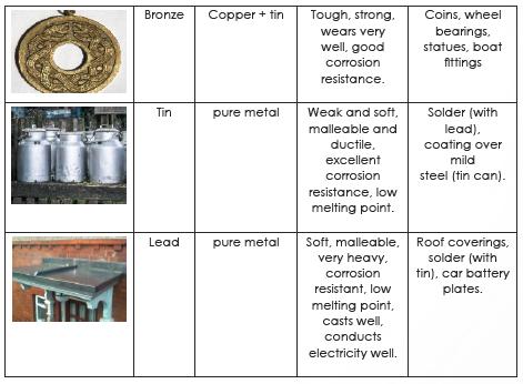
2 UNIT 1 - MATERIALS SECTION 3 METALS AND TREATMENTS Word Meaning Ferrous metal These are the metals that contain some iron. Non ferrous metal These are the metals that do not contain iron. Ferrous Non-Ferrous Contain Iron Magnetic Examples: cast iron, mild steel, stainless steel Do not contain iron Non magnetic Examples: aluminium, copper, lead, zinc, gold and silver

3
4 SECTION 4 PLASTICS AND COMPOSITES Word Thermosetting plastics Thermoplastics Composite Meaning Plastics that cannot be reshaped by heating but can withstand higher temperatures. Plastics that can be reshaped by heating A material that is made by combining two or more materials. They do not bind or merge together. Thermoplastics Heated and can be reshaped. Plastics become soft at a temperature lower than 100. Plastic bottles. Thermosetting Plastics Do not reshape with heat. Withstand higher heat than thermoplastics. Saucepan handles, electric socket. Carbon Fiber Reinforced Plastic (CFRP) Glass Reinforced Plastic (GRP) Known better as fiberglass Composite made from combining glass fibers and polyester resin Tough, rigid and lightweight Boat hulls, car body shells and canoes Most expensive composite. Best strength to weight ratio of any construction material It is made from high tensile strength carbon fibers which are woven together and then incased in a plastic resin. Resistant to stretching, rigid material, light in weight Can withstand high temperatures Formula One cars, racing bikes and helicopter blades


5 UNIT 2 FUNDAMENTAL OF ELECTRONICS SECTION 1 ELECTRICAL CIRCUITS Word Meaning Image Electrical Circuit A closed path for electrons to move through electrical components, connected by a conductive wire. Schematic Diagram Voltage A graphical representation of an electrical circuit that uses symbols. The charge difference between two points. Current The rate at which electric charge flows through a certain point. Resistance A material s tendency to resist (oppose) the flow of charge (current). DC AC Battery An electric current that flows in one direction and has a constant voltage level; used in devices that use batteries or USB cables for power An electric current that periodically changes its direction; the voltage level also reverses with the current; used to deliver power to houses, office buildings, etc. An electrical DC power source

6 INTRODUCTION We use electricity in our daily lives to power our electric devices. For example Cars get electric power from batteries. Computers, televisions, air conditioners, cell phone chargers & electric wall sockets. Electric current is the flow of electric charge carried by electrons. Electrons are very small particles within atoms. They carry electric energy and flow through defined paths known as electric circuits. Electronics is described as the science of dealing with electricity. For example - An electronic appliance has more functions than a simple electrical device. An electronic kettle could maybe send an SMS to your phone, telling you that your water is ready. A simple electric kettle ONLY boils water.

.")


7 ELECTRICAL SCHEMATIC Ohm s Law Voltage is the difference in charge between two points. Measured in Volts(V). Current is the rate at which charge is flowing. Measured in Amperes(A). Resistance is a material s tendency to resist the flow of charge (current). Measured in Ohms(Ω).

8 Problem 1: Using Ohm s Law, what is the voltage difference between point A and B if the current flowing through the resistor is 15 ma, and the resistance is 100 Ω? Solution: V = I R = A 100 Ω =1.5 V Problem 2: If the resistor in the previous example is replaced with another resistor, that has double the resistance, how much current would be flowing in the circuit using the same 1.5V battery as a voltage supply? Solution: V = 1.5 V, R = 2 100Ω = 200 Ω V = I R I = V / R = 1.5 V / 200 Ω = A = 7.5 ma Problem 3: Compare the value of the new current with the value of the initial current. Justify your answer. Solution: The new current is half the initial current (7.5 is half of 15). When the resistance was doubled, the current flowing became less (half the original current). This is because current is INVERSELY proportional to the resistance. BATTERIES A battery is a common DC power supply. A battery is made up of two plates. One plate is positively charged (+), the other plate is negatively charged (-). The plates are surrounded by a chemical solution called electrolyte. The electrical energy of a battery is made by converting the chemical energy of the battery. This happens when a chemical reaction between the plates and the electrolyte produces a voltage difference between the two plates. This makes the electrons flow and generates an electric current. The figure below shows some commonly used batteries that are available at the market. Each type has a different voltage.


 (min., max.")


9 SIGNAL - For receiving and sending information 1. Analog Signals This signal has infinite number of values. Stored in continuous form between minimum and maximum value. Examples Brightness of sun Room temperature Speaker Mixing colors Old radio Old photograph 2. Digital Signals These signals have a finite set of possible values(0v or 5V). Stored in coded form (0,1) (min., max. ) Examples Light switch in class room. Power button of phone. Game controller buttons Calculator screen Digital camera Digital music player SERIES CIRCUITS Electric current flows in ONE defined path in series circuits. The current must flow through the wires, all the way through both light bulbs and back to the battery. PARALLEL CIRCUITS In parallel circuits, electric current has more than one path. The components are connected to the same common points, this allows the current to be distributed over the paths.


10 SECTION 2 RESISTORS Word Meaning Image Types of Resistors Resistor Colour Code Table An electronic component that resists the flow of current in an electric circuit. A table used to find out the resistance value of the colour coded resistor. Resistors are also used to divide voltages. The schematic symbol is shown below Tolerance is the maximum electrical or mechanical variations plus or minus in the specifications tolerated without affecting the operations of the device.


11 The resistance of a resistor For the 4-band resistor, the tolerance is ±5%. This means that the real resistance of this resistor will not be exactly 1000 Ω. It might be +5% more or -5% less than 1000 Ω. So how much is 5% of 1000 Ω? Tolerance = ±5 % of 1000 Ω 5% of 1000 Ω = Ω= 50 Ω 100 Tolerance= ± (5 % of 1000) = ±50 Ω R=1000 Ω ± 50 Ω R is between ( ) Ω and ( ) Ω R is between (950) Ω and (1050) Ω We call this a range. So, the range of the resistance is {950 Ω to 1050 Ω}. For the 5-band resistor, the tolerance is ±1%. This means that the real resistance of this resistor will not be exactly 57 Ω. It might be +1% more or -1% less than 57 Ω. So how much is 1% of 57 Ω? Tolerance = ±1 % of 57 Ω 1% of 57 Ω = 1 57 Ω= 0.57 Ω 100 Tolerance= ± (1 % of 57) = ±0.57 Ω R= 57 Ω ± 0.57 Ω R is between ( ) Ω and ( ) Ω R is between (56.43) Ω and (57.57) Ω We call this a range. So, the range of the resistance is {56.43 Ω to Ω}.
 Nodes electronic components are connected to the nodes.")
 and numbers (rows) to help build the circuit properly. SECTION 4 EMBEDDED SYSTEMS Meaning A computer system that has a specific function within a larger system.")
12 Word Meaning Image Breadboard Multimeter An electronic base used for building prototypes for electric circuits. An electronic device used for measuring different electrical values. Word Embedded system SECTION 3 ELECTRONIC CALCULATIONS Breadboard There are three main components (1) Nodes electronic components are connected to the nodes. (2) Power Rails It is used to supply the board with power. Internally these nodes are connected vertically. (3) Terminal stripes These are the horizontally connected nodes. They are marked with letters (columns) and numbers (rows) to help build the circuit properly. SECTION 4 EMBEDDED SYSTEMS Meaning A computer system that has a specific function within a larger system. Multimeter It also checks the continuity in a circuit. The different values measured are - current (Amps AC & DC) - resistance (Ohms) - voltage (Volts AC or DC) - diode testing, - capacitance (Farads), - transistor testing, etc. It has two probes. Microcontroller Processing Input Output A minicomputer that fits on a single chip and controls a system. A series of actions / steps that lead to a certain result. The information or data entered into a system. The information or data produced by a system based on the input information.


13 Embedded systems : It is a specialized computer system with a specific function within a larger mechanical or electrical system. Examples include an air conditioner in car; a seatbelt warning in a car, a garden watering system & a motion sensitive security system. An embedded system is known as an input. It is a device that contains a computer unit or a microcontroller that reads the changes in an environment. It then controls an output system to change the environment. Controller : It is an electronic chip that works as a computer to manage the operation of electronic devices. It controls certain machines. It can be programmed to read input and controlling output. It has 3 main parts.

 Control")


14 Word Meaning Image SECTION 5 RELAY Relay It is an electromagnetic switch that can be enabled by a small electrical signal and controls a much larger electrical current. There are 2 main circuits in a relay system - (a) Control Circuit (b) Load Circuit When power flows through the first circuit, it activates the electromagnet which generates a magnetic field. This magnetic field attracts the connector and activates the second circuit. Applications - fridges, washing machines, dishwashers and AC controls.


15 Solid State Relays Relay Applications Have no coil, spring, or mechanical contact switch. Much faster response time than electromagnetic relays. Made from Semiconductor materials. Car Indicator Light Relays are used for powering car turning signal lights and many other devices. These are called flashers. It s a type of relay with three terminals and the body works as the earth, in old Japanese cars like old Toyotas. Fridge Relays are commonly used in home appliances, like refrigerators for example, where there is an electronic control turning on a motor..
Chapter 12 Electric Circuits
 Conceptual Physics/ PEP Name: Date: Chapter 12 Electric Circuits Section Review 12.1 1. List one way electric current is similar to water current and one way it is different. 2. Draw a circuit diagram
Electrical Functions Notes
 Electrical Functions Notes Electrical Function An electrical function is the role that a component plays in the control or transformation of electric current. Power Supplies Power supply is the electrical
Electrical Components and their Functions
 Electrical Components and their Functions Electricity & Electronics All electrical appliances and electronic devices depend on electrical circuits. The main difference between electricity & electronics
Lab 2.4 Arduinos, Resistors, and Circuits
 Lab 2.4 Arduinos, Resistors, and Circuits Objectives: Investigate resistors in series and parallel and Kirchoff s Law through hands-on learning Get experience using an Arduino hat you need: Arduino Kit:
4. The circuit in an appliance is 3A and the voltage difference is 120V. How much power is being supplied to the appliance?
 1 Name: Date: / / Period: Formulas I = V/R P = I V E = P t 1. A circuit has a resistance of 4Ω. What voltage difference will cause a current of 1.4A to flow in the 2. How many amperes of current will flow
Resistance and Ohm s law
 Resistance and Ohm s law Objectives Characterize materials as conductors or insulators based on their electrical properties. State and apply Ohm s law to calculate current, voltage or resistance in an
Basic Electricity 30 Hour - Part 1 Student Workbook Issue: US140/30/2a-IQ-0402A. Written by: LJ Technical Dept
 Basic Electricity 30 Hour - Part Issue: US40/30/a-IQ-040A Copyright 004,. No part of this Publication may be adapted or reproduced in any material form, without the prior written permission of. Written
Lab 2: Blinkie Lab. Objectives. Materials. Theory
 Lab 2: Blinkie Lab Objectives This lab introduces the Arduino Uno as students will need to use the Arduino to control their final robot. Students will build a basic circuit on their prototyping board and
What is meant by the term Demographic movement? Give one advantage and one disadvantage to demographic movement
 1.1 New and emerging technologies List 2 advantages to industry that have derived from new technologies Explain one reason why unemployment in the UK may rise as new and emerging technologies develop.
SECTION 3 BASIC AUTOMATIC CONTROLS UNIT 12 BASIC ELECTRICITY AND MAGNETISM. Unit Objectives. Unit Objectives 2/29/2012
 SECTION 3 BASIC AUTOMATIC CONTROLS UNIT 12 BASIC ELECTRICITY AND MAGNETISM Unit Objectives Describe the structure of an atom. Identify atoms with a positive charge and atoms with a negative charge. Explain
Date of Exam Morning Time allowed: 2 hours
 SPECIMEN MATERIAL Please write clearly, in block capitals. Centre number Candidate number Surname Forename(s) Candidate signature GCSE ENGINEERING Written Paper 8852/W Date of Exam Morning Time allowed:
ExamLearn.ie. Current Electricity
 ExamLearn.ie Current Electricity Current Electricity An electric current is a flow of electric charge. If a battery is connected to each end of a conductor, the positive terminal will attract the free
FCC Technician License Course
 FCC Technician License Course 2014-2018 FCC Element 2 Technician Class Question Pool Presented by: Tamiami Amateur Radio Club (TARC) WELCOME To the SECOND of 4, 3-hour classes presented by TARC to prepare
UNIVERSITY OF NORTH CAROLINA AT CHARLOTTE Department of Electrical and Computer Engineering
 UNIVERSITY OF NORTH CAROLINA AT CHARLOTTE Department of Electrical and Computer Engineering EXPERIMENT 2 BASIC CIRCUIT ELEMENTS OBJECTIVES The purpose of this experiment is to familiarize the student with
Syllabus OP49 Test electrical conduction in a variety of materials, and classify each material as a conductor or insulator
 Physics: 14. Current Electricity Please remember to photocopy 4 pages onto one sheet by going A3 A4 and using back to back on the photocopier Syllabus OP49 Test electrical conduction in a variety of materials,
CURRENT ELECTRICITY. 1. The S.I. unit of power is (a) Henry (b) coulomb (c) watt (d) watt-hour Ans: c
 Henry (b) coulomb (c) watt (d) watt-hour Ans: c") CURRENT ELECTRICITY 1. The S.I. unit of power is (a) Henry (b) coulomb (c) watt (d) watt-hour 2. Electric pressure is also called (a) resistance (b) power (c) voltage (d) energy 3. The substances which
CURRENT ELECTRICITY 1. The S.I. unit of power is (a) Henry (b) coulomb (c) watt (d) watt-hour 2. Electric pressure is also called (a) resistance (b) power (c) voltage (d) energy 3. The substances which
Electronics Review 2 Cornerstone Electronics Technology and Robotics II
 Electronics Review 2 Cornerstone Electronics Technology and Robotics II Administration: o Prayer o Bible Verse Hacksaws: o Vertical and horizontal positions o Hacksaw blade must be positioned with the
Introduction. Inductors in AC Circuits.
 Module 3 AC Theory What you ll learn in Module 3. Section 3.1 Electromagnetic Induction. Magnetic Fields around Conductors. The Solenoid. Section 3.2 Inductance & Back e.m.f. The Unit of Inductance. Factors
END-OF-SUBCOURSE EXAMINATION
 END-OF-SUBCOURSE EXAMINATION Circle the letter of the correct answer to each question. When you have answered all of the questions, use a Number 2 pencil to transfer your answers to the TSC Form 59. 1.
HANDS-ON LAB INSTRUCTION SHEET MODULE 3 CAPACITORS, TIME CONSTANTS AND TRANSISTOR GAIN
 HANDS-ON LAB INSTRUCTION SHEET MODULE 3 CAPACITORS, TIME CONSTANTS AND TRANSISTOR GAIN NOTES: 1) To conserve the life of the Multimeter s 9 volt battery, be sure to turn the meter off if not in use for
CURRENT, POTENTIAL DIFFERENCE AND RESISTANCE PART I
 CURRENT, POTENTIAL DIFFERENCE AND RESISTANCE PART I Q1. An electrical circuit is shown in the figure below. (a) The current in the circuit is direct current. What is meant by direct current? Tick one box.
Technician Licensing Class T6
 Technician Licensing Class T6 Amateur Radio Course Monroe EMS Building Monroe, Utah January 11/18, 2014 January 22, 2014 Testing Session Valid dates: July 1, 2010 June 30, 2014 Amateur Radio Technician
ELECTRIC CIRCUITS AND ELECTRONICS
 Circuitos eléctricos y electrónicos ELECTRIC CIRCUITS AND ELECTRONICS Technology, programming and robotics II Electric Circuitos circuits eléctricos and y electronics electrónicos AN ELECTRICAL CIRCUIT
Unit 4: Electricity (Part 1)
") Unit 4: Electricity (Part 1) Learning Outcomes Students should be able to: 1. Explain what is meant by current, potential difference and resistance, stating their units 2. Draw and interpret circuit diagrams
Unit 4: Electricity (Part 1) Learning Outcomes Students should be able to: 1. Explain what is meant by current, potential difference and resistance, stating their units 2. Draw and interpret circuit diagrams
Basic Electronics. Chapter 2 Basic Electrical Principles and the Functions of Components. PHYS 401 Physics of Ham Radio
 Basic Electronics Chapter 2 Basic Electrical Principles and the Functions of Components Figures in this course book are reproduced with the permission of the American Radio Relay League. This booklet was
Figure 1. Why is iron a suitable material for the core of a transformer?
 INDUCED POTENTIAL, TRANSFORMERS: NAT GRID Q1. Figure 1 shows the construction of a simple transformer. Figure 1 Why is iron a suitable material for the core of a transformer? Tick one box. It is a metal.
T6A4. Electrical components; fixed and variable resistors, capacitors, and inductors; fuses, switches, batteries
 Amateur Radio Technician Class Element Course Presentation ti ELEMENT SUB-ELEMENTS Technician Licensing Class Supplement T Electrical/Electronic Components Exam Questions, Groups T - FCC Rules, descriptions
ELEXBO. Electrical - Experimentation Box
 ELEXBO Electrical - Experimentation Box 1 Table of contents 2 Introduction...3 Basics...3 The current......4 The voltage...6 The resistance....9 Measuring resistance...10 Summary of the electrical values...11
Aim: To learn the resistor color codes and building a circuit on a BreadBoard. Equipment required: Resistances, millimeter, power supply
 Understanding the different components Aim: To learn the resistor color codes and building a circuit on a BreadBoard Equipment required: Resistances, millimeter, power supply Resistors are color coded
Wallace Hall Academy Physics Department. Electricity. Pupil Notes Name:
 Wallace Hall Academy Physics Department Electricity Pupil Notes Name: 1 Learning intentions for this unit? Be able to state that there are two types of charge; positive and negative Be able to state that
Electronics & Control
 Electronics & Control Analogue Electronics Introduction By the end of this unit you should be able to: Know the difference between a series and parallel circuit Measure voltage in a series circuit Measure
VCE VET INTEGRATED TECHNOLOGIES
 Victorian Certificate of Education 2015 SUPERVISOR TO ATTACH PROCESSING LABEL HERE Letter STUDENT NUMBER VCE VET INTEGRATED TECHNOLOGIES Written examination Monday 9 November 2015 Reading time: 9.00 am
Exam Practice Problems (3 Point Questions)
") Exam Practice Problems (3 Point Questions) Below are practice problems for the three point questions found on the exam. These questions come from past exams as well additional questions created by faculty.
Exam Practice Problems (3 Point Questions) Below are practice problems for the three point questions found on the exam. These questions come from past exams as well additional questions created by faculty.
Curriculum. Technology Education ELECTRONICS
 Curriculum Technology Education ELECTRONICS Supports Academic Learning Expectation # 3 Students and graduates of Ledyard High School will employ problem-solving skills effectively Approved by Instructional
Industrial Technology Electronics Technologies
 2010 HIGHER SCHOOL CERTIFICATE EXAMINATION Industrial Technology Electronics Technologies Total marks 40 General Instructions Reading time 5 minutes Working time 1 1 hours 2 Write using black or blue pen
Thursday 9 June 2016 Afternoon
 Oxford Cambridge and RSA Thursday 9 June 2016 Afternoon GCSE DESIGN AND TECHNOLOGY Industrial Technology A545/01 Sustainability and Technical Aspects of Designing and Making *2713717317* Candidates answer
Lesson 3: Electronics & Circuits
 Lesson 3: Electronics & Circuits Preparation for Amateur Radio Technician Class Exam Topics Review Ohm s Law Energy & Power Circuits Inductors & Inductance Capacitors & Capacitance Analog vs Digital Exam
SUBELEMENT T5 Electrical principles: math for electronics; electronic principles; Ohm s Law 4 Exam Questions - 4 Groups
 SUBELEMENT T5 Electrical principles: math for electronics; electronic principles; Ohm s Law 4 Exam Questions - 4 Groups 1 T5A Electrical principles, units, and terms: current and voltage; conductors and
CECS LAB 4 Prototyping Series and Parallel Resistors
 NAME: POSSIBLE POINTS: 10 NAME: NAME: DIRECTIONS: We are going to step through the entire process from conceptual to a physical prototype for the following resistor circuit. STEP 1 - CALCULATIONS: Calculate
Circuits: Light-Up Creatures Student Advanced version
 Circuits: Light-Up Creatures Student Advanced version In this lab you will explore current, voltage and resistance and their relationships as given by the Ohm s law. You will also explore of how resistance
EDEXCEL NATIONALS UNIT 5 - ELECTRICAL AND ELECTRONIC PRINCIPLES. ASSIGNMENT No.1 - RESISTOR NETWORKS
 EDEXCEL NATIONALS UNIT 5 - ELECTRICAL AND ELECTRONIC PRINCIPLES ASSIGNMENT No.1 - RESISTOR NETWORKS NAME: I agree to the assessment as contained in this assignment. I confirm that the work submitted is
Basic Electronics. Chapter 2, 3A (test T5, T6) Basic Electrical Principles and the Functions of Components. PHYS 401 Physics of Ham Radio
 Basic Electrical Principles and the Functions of Components. PHYS 401 Physics of Ham Radio") Basic Electronics Chapter 2, 3A (test T5, T6) Basic Electrical Principles and the Functions of Components Figures in this course book are reproduced with the permission of the American Radio Relay League.
Basic Electronics Chapter 2, 3A (test T5, T6) Basic Electrical Principles and the Functions of Components Figures in this course book are reproduced with the permission of the American Radio Relay League.
REQUIRED SKILLS AND KNOWLEDGE UEENEEE104A. Topic and Description NIDA Lesson CARD #
 REQUIRED SKILLS AND KNOWLEDGE UEENEEE104A KS01-EE104A Direct current circuits T1 Topic and Description NIDA Lesson CARD # Basic electrical concepts encompassing: electrotechnology industry static and current
SUBELEMENT T6 Electrical components: semiconductors; circuit diagrams; component functions 4 Exam Questions - 4 Groups
 SUBELEMENT T6 Electrical components: semiconductors; circuit diagrams; component functions 4 Exam Questions - 4 Groups 1 T6A Electrical components: fixed and variable resistors; capacitors and inductors;
Q2. Figure 1 shows the oscilloscope trace an alternating current (a.c.) electricity supply produces.
 electricity supply produces.") SERIES AND PARALEL CIRCUITS Q1. A student set up the electrical circuit shown in the figure below. (a) The ammeter displays a reading of 0.10 A. Calculate the potential difference across the 45 Ω resistor.
SERIES AND PARALEL CIRCUITS Q1. A student set up the electrical circuit shown in the figure below. (a) The ammeter displays a reading of 0.10 A. Calculate the potential difference across the 45 Ω resistor.
Experiment P-24 Circuits and Series Resistance
 1 Experiment P-24 Circuits and Series Resistance Objectives To study the relationship between the voltage applied to a given resistor and the intensity of the current running through it. Modules and Sensors
Simple Circuits Experiment
 Physics 8.02T 1 Fall 2001 Simple Circuits Experiment Introduction Our world is filled with devices that contain electrical circuits in which various voltage sources cause currents to flow. We use radios,
Resistance and Ohm s Law R V I. 1 ohm = 1 volt ampere
 Resistance and Ohm s Law If you maintain an electric potential difference, or voltage V, across any conductor, an electric current occurs. In general, the magnitude of the current depends on the potential
STUDENT NUMBER Letter VCE VET ELECTRONICS. Written examination. Monday 31 October 2005
 Victorian CertiÞcate of Education 2005 SUPERVISOR TO ATTACH PROCESSING LABEL HERE Figures Words STUDENT NUMBER Letter VCE VET ELECTRONICS Written examination Monday 31 October 2005 Reading time: 9.00 am
Design and Technology
 E.M.F, Voltage and P.D E.M F This stands for Electromotive Force (e.m.f) A battery provides Electromotive Force An e.m.f can make an electric current flow around a circuit E.m.f is measured in volts (v).
Introduction to Electronics and Breadboarding Circuits
 Introduction to Electronics and Breadboarding Circuits What we're going to learn today: What is an electronic circuit? What kind of power is needed for these projects? What are the fundamental principles
Experiment P-10 Ohm's Law
 1 Experiment P-10 Ohm's Law Objectives To study the relationship between the voltage applied to a given resistor and the intensity of the current running through it. Modules and Sensors PC + NeuLog application
Wallace Hall Academy. CfE Higher Physics. Unit 3 - Electricity Notes Name
 Wallace Hall Academy CfE Higher Physics Unit 3 - Electricity Notes Name 1 Electrons and Energy Alternating current and direct current Alternating current electrons flow back and forth several times per
Electronic Components (Elements)
") Lecture_3 Electronic Components (Elements) Instructor: IBRAHIM ABU-ISBEIH 25 July 2011 Reverse Engineering 1 Objectives: After completing this class, you will be able to identify the most commonly used
Lecture_3 Electronic Components (Elements) Instructor: IBRAHIM ABU-ISBEIH 25 July 2011 Reverse Engineering 1 Objectives: After completing this class, you will be able to identify the most commonly used
Laboratory Project 1a: Power-Indicator LED's
 2240 Laboratory Project 1a: Power-Indicator LED's Abstract-You will construct and test two LED power-indicator circuits for your breadboard in preparation for building the Electromyogram circuit in Lab
Experiment 3. Ohm s Law. Become familiar with the use of a digital voltmeter and a digital ammeter to measure DC voltage and current.
 Experiment 3 Ohm s Law 3.1 Objectives Become familiar with the use of a digital voltmeter and a digital ammeter to measure DC voltage and current. Construct a circuit using resistors, wires and a breadboard
EET 1150 Lab 6 Ohm s Law
 Name EQUIPMENT and COMPONENTS Digital Multimeter Trainer with Breadboard Resistors: 220, 1 k, 1.2 k, 2.2 k, 3.3 k, 4.7 k, 6.8 k Red light-emitting diode (LED) EET 1150 Lab 6 Ohm s Law In this lab you ll
Experiment 2. Ohm s Law. Become familiar with the use of a digital voltmeter and a digital ammeter to measure DC voltage and current.
 Experiment 2 Ohm s Law 2.1 Objectives Become familiar with the use of a digital voltmeter and a digital ammeter to measure DC voltage and current. Construct a circuit using resistors, wires and a breadboard
Design and Technology: Resistant Materials Technology Unit 2: Knowledge and Understanding of Resistant Materials Technology
 Write your name here Surname Other names Pearson Edexcel GCSE Centre Number Candidate Number Design and Technology: Resistant Materials Technology Unit 2: Knowledge and Understanding of Resistant Materials
ENGR 1181 Lab 3: Circuits
 ENGR 1181 Lab 3: Circuits - - Lab Procedure - Report Guidelines 2 Overview of Circuits Lab: The Circuits Lab introduces basic concepts of electric circuits such as series and parallel circuit, used in
Embedded Systems Analog Electronics
 Embedded Systems Analog Electronics Units physical units = length [meter], mass [kilogram], time [second] force - [Newton]: kg m/s 2 (F=ma) torque - [N m] energy - [joule]: 1N acting through distance of
Current Electricity. What is Current Electricity? Electrical Circuits Electrochemical Cells. Wet, Dry and Fuel Cells
 Current Electricity What is Current Electricity? Electrical Circuits Electrochemical Cells Wet, Dry and Fuel Cells Current Electricity Current Electricity continuous flow of electrons in a closed circuit
EXAMPLE. Use this jack for the red test lead when measuring. current from 0 to 200mA. Figure P-1
 Digital Multimeters ON / OFF power switch Continuity / Diode Test Function Resistance Function Ranges from 200Ω to 200MΩ Transistor Test Function DC Current Function Ranges from 2mA to 20A. AC Current
Trade of Electrician. The Transformer
 Trade of Electrician Standards Based Apprenticeship The Transformer Phase 2 Module No. 2.1 Unit No. 2.1.10 COURSE NOTES Created by Gerry Ryan - Galway TC Revision 1 April 2000 by Gerry Ryan - Galway TC
Standard Grade Physics
 Standard Grade Physics North Berwick High School Physics Department UNIT 2 Homework Sheets Working at Home TO THE PUPIL Each day you have physics at school, you should set aside time for work at home.
WJEC LEVEL 1-2 AWARDS IN ENGINEERING
 WJEC LEVEL 1-2 AWARDS IN ENGINEERING SAMPLE EXTERNAL ASSESSMENT VERSION 3 UNIT 3: SOLVING ENGINEERING PROBLEMS For first teaching from 2013 Contents Page Question Papers Specimen Mark Schemes Assessment
LED ROBOT BLINKER KIT
 LED ROBOT BLINKER KIT MODEL K-17 Assembly and Instruction Manual ELENCO Copyright 2016, 1998 by ELENCO Electronics, Inc. All rights reserved. Revised 2013 REV-P 753217 No part of this book shall be reproduced
GCSE 4111/01 DESIGN AND TECHNOLOGY UNIT 1 FOCUS AREA: Resistant Materials Technology
 Surname Other Names Centre Number 0 Candidate Number GCSE 4111/01 DESIGN AND TECHNOLOGY UNIT 1 FOCUS AREA: Resistant Materials Technology A.M. WEDNESDAY, 15 May 2013 2 hours ADDITIONAL MATERIALS Question
FCC Technician License Course
 FCC Technician License Course 2018-2022 FCC Element 2 Technician Class Question Pool Presented by: Tamiami Amateur Radio Club (TARC) WELCOME To the SECOND of 3, 4-hour classes presented by TARC to prepare
Electronic component
 Electronic component Electronic component: An electronic component is any basic discrete device or physical entity in an electronic system used to affect electrons or their associated fields. 2 TYPES OF
YAL. 12 Electricity. Assignments in Science Class X (Term I) IMPORTANT NOTES
 IMPORTANT NOTES") Assignments in Science Class X (Term I) 12 Electricity IMPORTANT NOTES 1. There are two kinds of electric charges i.e., positive and negative. The opposite charges attract each other and the similar charges
Assignments in Science Class X (Term I) 12 Electricity IMPORTANT NOTES 1. There are two kinds of electric charges i.e., positive and negative. The opposite charges attract each other and the similar charges
Lab 3 DC CIRCUITS AND OHM'S LAW
 43 Name Date Partners Lab 3 DC CIRCUITS AND OHM'S LAW AMPS + - VOLTS OBJECTIVES To learn to apply the concept of potential difference (voltage) to explain the action of a battery in a circuit. To understand
ELEC1 (JUN13ELEC101) General Certificate of Education Advanced Subsidiary Examination June Introductory Electronics TOTAL. Time allowed 1 hour
 General Certificate of Education Advanced Subsidiary Examination June Introductory Electronics TOTAL. Time allowed 1 hour") Centre Number Surname Candidate Number For Examiner s Use Other Names Candidate Signature Examiner s Initials Question Mark General Certificate of Education Advanced Subsidiary Examination June 2013 1
Centre Number Surname Candidate Number For Examiner s Use Other Names Candidate Signature Examiner s Initials Question Mark General Certificate of Education Advanced Subsidiary Examination June 2013 1
ELECTRIC CURRENT VERY SHORT ANSWER QUESTIONS
 ELECTRIC CURRENT VERY SHORT ANSWER QUESTIONS 1. Give the equivalent of V A -1. 2. Ten identical wires, each having a resistance of one ohm, are joined in parallel. What is the equivalent resistance of
Circuit Board Assembly Instructions for Babuinobot 1.0
 Circuit Board Assembly Instructions for Babuinobot 1.0 Brett Nelson January 2010 1 Features Sensor4 input Sensor3 input Sensor2 input 5v power bus Sensor1 input Do not exceed 5v Ground power bus Programming
A resistor adds resistance to a circuit. Describe what the effect of adding resistance would have on the current flowing in the circuit.
 A. Current, Potential Difference and Resistance 1a A student builds a circuit. The circuit is shown in Figure 1. Label the components shown in Figure 1. (3) Figure 1 Voltmeter Power Supply Diode Resistor
Solar Sound Module Shannon McMullen Fabian Winkler
 Solar Sound Module http://www.cla.purdue.edu/vpa/etb/ Shannon McMullen Fabian Winkler Based on a workshop of the same name by Ralf Schreiber See: http://www.ralfschreiber.com/solarsound/solarsound.html
Voltage, Current and Resistance
 Voltage, Current and Resistance Foundations in Engineering WV Curriculum, 2002 Foundations in Engineering Content Standards and Objectives 2436.8.3 Explain the relationship between current, voltage, and
The Art of Electrical Measurements
 The Art of Electrical Measurements Purpose: Introduce fundamental electrical test and measurement tools and the art of making electrical measurements. Equipment Required Prelab 1 Digital Multimeter 1 -
VCE VET ELECTROTECHNOLOGY
 Victorian Certificate of Education 2009 SUPERVISOR TO TTCH PROCESSING LBEL HERE STUDENT NUMBER Letter Figures Words VCE VET ELECTROTECHNOLOGY Written examination Thursday 5 November 2009 Reading time:
PHYSICS 3204 PUBLIC EXAM QUESTIONS (Electric Circuits)
") PHYSICS 3204 PUBLIC EXAM QUESTIONS (Electric Circuits) NAME: August 2009------------------------------------------------------------------------------------------------------------------ 26. What is the
PHYSICS 3204 PUBLIC EXAM QUESTIONS (Electric Circuits) NAME: August 2009------------------------------------------------------------------------------------------------------------------ 26. What is the
Activity Electrical Circuits Simulation
 Activity 1.2.3 Electrical Circuits Simulation Introduction Since the late 1800s, engineers have designed systems to utilize electrical energy due to its ability to be converted, stored, transmitted, and
AC/DC ELECTRONICS LABORATORY
 Includes Teacher's Notes and Typical Experiment Results Instruction Manual and Experiment Guide for the PASCO scientific Model EM-8656 012-05892A 1/96 AC/DC ELECTRONICS LABORATORY 1995 PASCO scientific
Cambridge International Examinations Cambridge International General Certificate of Secondary Education
 Cambridge International Examinations Cambridge International General Certificate of Secondary Education *4342807288* PHYSICS 0625/32 Paper 3 Theory (Core) October/November 2017 1 hour 15 minutes Candidates
Activity Sheet Solutions
 Activity Sheet Solutions Health & Safety 2 Q. 1 Only one person at a time allowed on the machine Wear safety goggles when drilling Grip the metal tightly in the vice Q. 2 To prevent accidents Q. 3 Keep
ASE 6 - Electrical Electronic Systems. Module 3 Properties of Electricty
 Electronic Systems Module 3 Acknowledgements General Motors, the IAGMASEP Association Board of Directors, and Raytheon Professional Services, GM's training partner for GM's Service Technical College wish
total j = BA, [1] = j [2] total
![total j = BA, [1] = j [2] total](/thumbs/85/91692343.jpg "total j = BA, [1] = j [2] total") Name: S.N.: Experiment 2 INDUCTANCE AND LR CIRCUITS SECTION: PARTNER: DATE: Objectives Estimate the inductance of the solenoid used for this experiment from the formula for a very long, thin, tightly wound
Name: S.N.: Experiment 2 INDUCTANCE AND LR CIRCUITS SECTION: PARTNER: DATE: Objectives Estimate the inductance of the solenoid used for this experiment from the formula for a very long, thin, tightly wound
Activity Electrical Circuits Simulation
 Activity 1.2.3 Electrical Circuits Simulation Introduction Since the late 1800s, engineers have designed systems to utilize electrical energy due to its ability to be converted, stored, transmitted, and
Laboratory Project 1B: Electromyogram Circuit
 2240 Laboratory Project 1B: Electromyogram Circuit N. E. Cotter, D. Christensen, and K. Furse Electrical and Computer Engineering Department University of Utah Salt Lake City, UT 84112 Abstract-You will
Table of Contents. Introduction...2 Conductors and Insulators...3 Current, Voltage, and Resistance...6
 Table of Contents Introduction...2 Conductors and Insulators...3 Current, Voltage, and Resistance...6 Ohm s Law... 11 DC Circuits... 13 Magnetism...20 Alternating Current...23 Inductance and Capacitance...30
Chapter 2: Your Boe-Bot's Servo Motors
 Chapter 2: Your Boe-Bot's Servo Motors Vocabulary words used in this lesson. Argument in computer science is a value of data that is part of a command. Also data passed to a procedure or function at the
DEPARTMENT OF ELECTRONIC ENGINEERING ELECTRONIC WORKSHOP # 03. Resistors
 MEHRAN UNIVERSITY OF ENGINEERING AND TECHNOLOGY, JAMSHORO DEPARTMENT OF ELECTRONIC ENGINEERING ELECTRONIC WORKSHOP # 03 Resistors Roll. No: Checked by: Date: Grade: Object: To become familiar with resistors,
Electric Current - 1 v Goodman & Zavorotniy
 Chapter Problems Electric Current Classwork 1. If 560 C of electric charge passed through a light bulb in 8 min; what was the magnitude of the average electric current passing through the bulb? 2. If the
South Pasadena A.P. Physics Chapter Electric Current & DC Circuits Date / / Period Electricity Practice Test
 South Pasadena A.P. Physics Name Chapter 18-19 Electric Current & DC Circuits Date / / Period 1 2 3 4 Electricity Practice Test Electric Current I = Q/t 1. A charge of 30 Coulombs passes through a 24-ohm
Electrical Measurements
 Electrical Measurements INTRODUCTION In this section, electrical measurements will be discussed. This will be done by using simple experiments that introduce a DC power supply, a multimeter, and a simplified
Unit 1 Electronics Name: Form:
 Unit 1 Electronics Name: Form: Electronics Electronics is the study of components and techniques used to be able to build circuits controlled by electricity. An electronic system uses discrete components.
Magnetism Quiz. Name: Class: Date: ID: A. Multiple Choice Identify the choice that best completes the statement or answers the question.
 Name: Class: Date: ID: A Magnetism Quiz Multiple Choice Identify the choice that best completes the statement or answers the question. 1. Electric current can best be induced in a wire by a. stretching
Series and parallel resistances
 Series and parallel resistances Objectives Calculate the equivalent resistance for resistors connected in both series and parallel combinations. Construct series and parallel circuits of lamps (resistors).
Workshop Part Identification Lecture N I A G A R A C O L L E G E T E C H N O L O G Y D E P T.
 Workshop Part Identification Lecture N I A G A R A C O L L E G E T E C H N O L O G Y D E P T. Identifying Resistors Resistors can be either fixed or variable. The variable kind are called potentiometers
VCE VET ELECTROTECHNOLOGY
 Victorian Certificate of Education 2010 SUPERVISOR TO ATTACH PROCESSING LABEL HERE STUDENT NUMBER Letter Figures Words VCE VET ELECTROTECHNOLOGY Written examination Thursday 4 November 2010 Reading time: