GUIDANCE, NAVIGATION, AND CONTROL
|
|
|
- Laura Lawson
- 5 years ago
- Views:
Transcription
1 e GUIDANCE, NAVIGATION, AND CONTROL QUICK REFERENCE DATA PRIMARY GUIDANCE AND NAVIGATION SECTION Navigation base Weight Diameter Leg length (approx) Material Inertial measurement unit Weight (approx) Diameter Temperature Alignment optical telescope Number of detent positions Field of view of each detent Counter readout Length Computer control and reticle dimmer assembly Height Width Depth Weight Pulse torque assembly Height Width Depth Weight Power and servo assembly Height Width Depth Weight Coupling data unit Number of channels Height Width Depth Weight LM guidance computer Computer type Internal transfer Memory Erasable Fixed 3 pounds 14 inches 10 inches Beryillium 42 pounds 12.5 inches +126O F 6 60' OOO.OOo to ' 36 inches inches inches inches 3 pounds inches 11 inches 13 inches 15 pounds inches inches inches 20 pounds inches 11-1/3 inches 20 inches 35 pounds Automatic, electronic, digital, general-purpose and control Parallel (all bits simultaneously) Random access Coincident-current core; 2,048-word capacity Core rope; 36,864-word capacity GN-1
2 LM guidance computer (cont) Word length Number system Circuitry type Memory cycle time Add time Basic clock oscillator Power Supplies Logic Parity 16 bits Binary 1's complement - for manipulation, Flat pack, NOR micrologic 12 microseconds 24 microseconds MHz One +4-volt and one t14-volt switching regulator; operated from 28-volt d-c input power Positive (Positive dc = Binary 1 ; 0 volts = Binary 0) Odd ABORT GUIDANCE SECTION Data entry and display assembly Height Width Depth Weight Logic' levels Clock frequency Abort electronics assembly Computer type Height Width Depth Weight Power Logic levels Clock frequency Memory capacity Fixed Erasable Word Size Abort sensor assembly Height Width Depth Weight Clock frequency Operating temperature 7.3 inches 6.6 inches 5.6 inches 8.4 pounds Zero: 0 to 0.5 vdc One: +3 to +5 vdc 128 kpps Automatic, electronic, digital, general-purpose 23.7 inches 9.0 inches 5.0 inches 32.5 pounds 12.5 watts (standby) 96.0 watts (operate) Zero: 0 to 0.5 vdc One: +3 to t5 vdc 1,024 pps 4,096 words 2,048 words 2,048 words 18 bits 5.1 inches 9.0 inches 13.5 inches 20.7 pounds (with support) 128 kpps +120 F GN-2
3 ?.., *,&, CONTROL ELECTRONICS SECTION c) Attitude and translation controller assembly Input signals Attitude error, command rate, and rate gyro output Operating frequency 800 Hz Cooling Conduction through mounting flanges Temperature range 0' to +160 F Rate gyro assembly Input power Starting power Input range Input rate frequency Descent engine control assembly A-C input power nominal voltage Operating temperature range D-C input power nominal voltage Total power consumption Single- and three-phase, 800 HZ 1.8 watts (maximum; three-phase) -25O to +25O per second 20 f 4 Hz 115 vrms +57O to +97O F +4, +I 5, +28, and -1 5 volts dc 7.9 watts (maximum) a Gimbal drive actuator A-C power A-C power consumption (steady-state average) 115 f 2.5 vrms, single phase, 400 Hz 35 watts Stroke +2 to -2 inches 55% Gimbal position +6O to -6' 55% Gimbal rate 0.2OIsec? I 0% Frequency of operation 5.0 Hz (maximum) Attitude controller assembly Operating power Type of sensor Displacement 28 volts. 800 Hz Proportional transducer 0.28 volt/degree Thrust/translation controller assembly Operating power Type of sensor 28 volts, 800 Hz Proportional transducer GN-3 I

4 LANDING RADAR Velocity sensor Radar altimeter Altitude capability Velocity capability Weight (approx) Power consumption Heater power consumption Altimeter antenna TY Pe RF power Velocity sensor antenna Type RF power Transmitter frequency Velocity sensor Radar altimeter Warmup time FM sweep duration Acquisition time Primary power Temperature range Electronics assembly Antenna assembly Continuous-wave, three-beam Frequency modulated/continuous wave (FM/CW) 10 to 25,000 feet From altitude of 18,000 feet 39 pounds 125 watts dc (nominal) 147 watts dc (maximurn) 44 watts dc (maximum) Planar array, space-duplexed 100 mw (minimum) Planar array, space-duplexed 200 mw (minimum) ghz 9.58 ghz 1 minute second 12 seconds (maximum) 25 to 31.5 volts dc (nominal) 3.5 to 6.5 amperes -20' to +I IOo F +50 to +150 F GN-4
5 0 NEWS REFERENCE RENDEZVOUS RADAR AND TRANSPONDER Rendezvous radar Radar radiation frequency Radar received frequency Radiated power Antenna design Angle-tracking method Antenna diameter Antenna beamwidth Gyroscopes Modulation Receiver channels Receiver intermediate frequencies Range Range accuracy Range data output Range rate Range rate accuracy Complete acquisition time Angular accuracy 5 to 400 nm Transponder Weight Antenna Transmit frequency Receive frequency Radiated power Acquisition time Intermediate frequencies First IF Second IF Modulation Range Range accuracy Range rate accuracy Input power Heater mhz mhz +_ Doppler 300 mw (nominal) Cassegrainian Amplitude monopulse 24 inches 4.0' 4 (two redundant) Phase modulation by three tones: 200 Hz, 6.4 khz, and khz Reference, shaft (pitch), and trunnion (yaw) 40.8,6.8, and 1.7 mhz 80 feet to 400 nm 1% or 80 feet for ranges between 80 feet and 5 nm; or 300 feet for ranges between 5 and 400 nm 15-bit serial format +4,900 to -4,900 fps fl fps 15 seconds 0.1 2' to 0.24' 16.0 pounds 4-inch Y-horn, linearly polarized 12-inch interconnecting waveguide 9792 mhz mhz *one-way Doppler 300 mw 1.8 seconds with 98% probability 40.8 mhz 6.8 mhz Phase modulation by three tones (200 Hz, 6.4 khz, khz) 80 feet to 400 nm Equal to maximum ranging error 0.25% or 1 fps (whichever is greater) 75 watts 20 watts (maximum) i GN-5
6 The LM is designed to take two astronauts from the orbiting CSM to the lunar surface and back again. The primary function of the Guidance, Navigation, and Control Subsystem (GN&CS) is accumulation, analysis, and processing of data to ensure the LM follows a predetermined flight plan at all times. To perform these functions, the guidance portion must know present position and velocity with respect to the guidance goal. The G'N&CS provides navigation,.guidance, and flight control to accomplish the specific guidance goal. The astronaut is an active and controlling element of the LM. He can monitor information to and from the various LM subsystems and can manually duplicate the various control functions. During completely automatic flight, the astronaut functions as a monitor and decision maker; during semiautomatic flight, he is a controlling influence on the automatic system; and during manually controlled flight he may perform all GN&CS functions himself. The astronaut can also initiate an optical sighting program, utilizing celestial objects to align the guidance equipment. Using cabin displays and controls, the astronaut can select modes of operation necessary to perform a desired function. In some mission phases, sequencing of modes of operation is automatically controlled by a computer. As calculations are performed by the computer, the results are displayed for astronaut evaluation and verification with ground-calculated data. In the event of failure of automatic control, the astronaut manually controls the LM and performs vehicle flight control normally performed by the computer. He does,this with a pair of hand controllers, which control attitude and translation, and with other controls on the cabin panels. For purposes of the following discussion, a distinction is made between guidance (orbital alteration or redirection of the LM) and navigation (accumulation and processing of data to define the proper guidance to be accomplished). NAVIGATION AND THE LUNAR MODULE LM navigation involves the determination of the vehicle's present position and velocity so that the guidance function can plot the trajectory that the LM must follow. When flying an aircraft between two points on earth, both points remain fixed with respect to each other. In spaceflight, however, the origin of the spacecraft's path and its distination or target are moving rapidly with respect to each other. To determine the present position of the LM, celestial navigation is used to align the guidance system. This is accomplished by determining the vehicle's position in relation to certain fixed stars. Even though the stars may be moving, the distance that they move in relation to the total distance of the stars from the vehicle is so small that the stars can be thought of as being stationary. The optical device which the astronauts use for navigation is an alignment optical telescope (AOT) protruding through the top of the vehicle and functioning as a sextant. The astronauts use it to take direct visual sightings and precise angular measurements of pairs of celestial objects. These measurements are transferred by the astronaut to the guidance elements to compute the position and velocity of the vehicle and to perform alignment of an inertial guidance system. There is a direct relationship between the angular measurements taken with the telescope and the mounting position of the telescope. The computer program knows the telescope's mounting position which is in alignment with the LM body axes and from this knowledge and astronaut-generated information, the computer is able to calculate the LM position. During the landing phase and subsequent rendezvous phase, the LM uses radar navigational techniques to determine distance and velocity. Each phase uses a radar designed specifically for that phase (rendezvous radar, landing radar). Both radars inform the astronaut and the computer concerning position and velocity relative to acquired target. During lunar landing, the target is the surface of the moon; during rendezvous, the target is the Command Module. GN-6
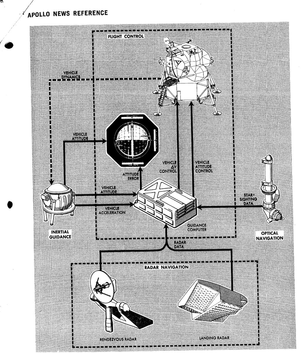
7 R-44 GN-7
8 GUIDANCE AND THE LUNAR MODULE After the position and velocity of the LM are determined, the guidance function establishes the steering for the predetermined flight path. Since objects in space are moving targets (as compared to those on earth, which are stationary), the guidance problem involves aiming not at the target s present position but at the position in which it will be when the vehicle path intersects the target path. On earth, the guidance problem is a twodimensional one; it involves only longitude and latitude. In space, a third dimension is introduced; position cannot be plotted in earth terms. To calculate the guidance parameters, a reference coordinate frame must be determined. A threeaxis, right-hand, orthogonal, coordinate frame (inertial reference frame) is used. It is fixed in space and has an unchanging angular relationship with the stars. Its dimensional axes are designated as X, Y, and 2, and all spacecraft positions and velocities are related to this frame. The astronaut establishes this frame by sighting of celestial objects using the AOT. The vertical axis is designated as the X-axis. Its positive direction is from the descent stage to the ascent stage, passing through the overhead hatch. The lateral axis is designated as the Y-axis. Its positive direction is from left to right across the astronauts shoulders when they are facing the windows in the LM cabin. To complete the three three-axis orthogonal system, the Z-axis is perpendicular to the X and Y axes. This axis is referred to as the forward axis, because +Z-axis direction is through the forward hatch. The +Z-axis is also used as the zero reference line for all angular measurements. The guidance system based on this coordinate frame is referred to as an inertial guidance system. Inertial guidance provides information about the actual path of the vehicle in relation to a predetermined path. All deviations are transmitted to a flight control system. The inertial guidance system performs these functions without information from outside the vehicle. The system stores the predetermined flight plan, then automatically but not continuously, computes distance and velocity for a given mission time (called the state vector) of the vehicle to compensate, through vehicle control, for changes in direction. R-45 + X-AXIS.t. - X-AXIS LM Vehicle Axes Inertial guidance systems are based on measurements made by accelerometers mounted on a structure called the stable member or platform. The stable member, in turn, is mounted inside three spherical gimbals, one for each principal axis of motion. Gyroscopes mounted on the stable member drive the gimbals to isolate the stable member from changes in LM attitude and hold the stable member in a fixed inertial position. During flight, the stable member s axes must be held in fixed relation to the inertial reference frame regardless of the LM motion; otherwise resolvers mounted on each gimbal issue error signals. These error signals are used by the computer to generate commands to correct the attitude of the LM. The rotational axes of the LM are designated as yaw, pitch, and roll. Yaw rotation, about the X-axis affects the vehicle in the Y-Z plane. The effect is analogous to spinning around one s heels. Pitch rotation, about the Y-axis, affects the vehicle in the X-Z plane. The effect is analogous to a gymnast performing a somersault. Roll rotation, about the Z-axis, affects the vehicle in the X-Y plane. The effect is analogous to a person doing a GN-8

9 :./ cartwheel. Positive rotation is determined by the right-hand rule, This involves placing the thumb of the right hand in the positive direction of the axis about which rotation is to be determined. Then the remainder of the fingers are curled around the axis. The direction in which the fingers point is considered the direction of positive rotation. FLIGHT CONTROL AND THE LUNAR MODULE Flight control involves controlling the LM trajectory (flight path) and attitude. Flight path control depends on the motion of the LM center of gravity; attitude control primarily involves rotations about the center of gravity. In controlling the LM in its flight path, the thrust of its engines must be directed so that it produces a desired variation in either magnitude or direction to place the LM in some particular orbit, position, or attitude. The major velocity changes associated with the lunar orbit, injection, landing, and ascent phases of the mission are accomplished by either the descent propulsion section or ascent propulsion section of the Main Propulsion Subsystem (MPS). The engines can produce high thrust in specific directions in inertial space. During the descent phase, the LM must be slowed (braked) to place it in a transfer orbit from which it can make a soft landing on the lunar surface. To accomplish braking, descent engine thrust is controllable so that the precise velocity (feet per second) necessary to alter the vehicle s trajectory can be achieved. For a soft landing on the lunar surface, the weight of the LM must be matched by an upward force so that a state of equilibrium exists, and from this point, the descent engine is shut off and the LM free falls to the lunar surface. The thrust of the descent engine provides this upward force, and since the weight of the vehicle is a variable (due to consumption of expendables) this is another reason why the magnitude of the engine thrust is controllable. In addition, the center of gravity is also variable and the thrust must be such that it is in line with the LM center of gravity. This is accomplished by gimbaling (tilting) the descent engine. R-46 LM Powered Descent Profile GN-9
 thruster.")
10 LM Powered Ascent Profile During the lunar ascent phase, the flight control portion of the GN&CS commands the ascent engine. In this phase, control of the thrust direction is not achieved by gimbaling the engine, but by attitude control, Lasing the Reaction Control Subsystem (RCS) thruster. This is necessary during ascent to keep the vehicle stabilized, because the center of gravity changes due to propellant depletion. The ascent engine is not throttleable, since the function of this engine is to lift the ascent stage from the lunar surface and conduct rendezvous. The proper orbit for rendezvous is achieved by means of a midcourse correction (if necessary) in which thrust directed by attitude control, and thrust magnitude is controlled by controlling the duration of the burn. It is apparent then for flight control, that some measure of the LM velocity vector and its position must be determined at all times for purposes of comparison with a desired (predetermined) velocity vector, at any particular instant, to generate an error signal if the two are not equal. The flight control portion of the primary guidance and navigation section then directs the thrust to reduce the error to zero. Attitude control maintains the LM body axes in a fixed relationship to the inertial reference axes. Any pitch, roll, or yaw rotations of the vehicle produce a misalignment between the LM axes and where the LM axes should be. This is called attitude error and is detected by the inertial guidance system, which, in turn, routes the errors to the computer. The computer generates on and off commands for the RCS to reduce the error to zero. Attitude control is implemented through 16 rocket engine thrusters (100-pounds thrust each) equally distributed in clusters of four around the ascent stage. Each cluster is located so that it will exert sufficient torque to rotate the LM about its center of gravity. The thrusters are capable of repeated starts and very short (fraction of second) firing times. The appropriate thrusters are selected by the computer during automatic operation and manually by the astronaut during manual operation. GN-10


11 , :/bpollo NEWS REFERENCE Because the astronauts frequently become part of the control loop in this highly flexible system, a great deal of information must be displayed for their use. These displays include attitude and velocity, radar data, fuel and oxidizer parameters, caution and warning information, total velocity change information, timing and other information to assist them in completing their mission. PRIMARY GUIDANCE AND NAVIGATION SECTION The primary guidance and navigation section acts as an autopilot in controlling the LM throughout the mission. Normal guidance requirements include transferring the LM from a lunar orbit to its descent profile, achieving a successful landing at a pres el ected or crew-selected site, and performing a powered ascent maneuver which results in terminal rendezvous with the CSM. If the mission is to be aborted, the primary guidance and navigation section performs guidance maneuvers that place the LM in a parking orbit or in a trajectory that intercepts the CSM. The navigational functional requirement of the section is that it provides the navigational data required for LM guidance. These data include lineof-sight (LOS) data from the AOT for inertial reference alignment, signals for initializing and aligning the abort guidance section, and data to the astronauts for determining the location of the computed landing site.
12 The primary guidance and navigation section includes three major subsections: inertial, optical, and computer. Individually or in combination they perform all the functions mentioned previously. The inertial subsection establishes the inertial reference frame that is used as the central coordinate system from which all measurements and computations are made. The inertial subsection measures attitude and incremental velocity changes, and assists in converting data for computer use, onboard display, or telemetry. Operation is started automatically by the guidance computer or by an astronaut using the computer keyboard. Once the subsection is energized and aligned to the inertial reference, any LM rotation (attitude change) is sensed by the stable member. All inertial measurements (velocity and attitude) are with respect to the stable member. These data are used by the computer in determining solutions to the guidance problems. The optical subsection is used to determine the position of the LM, using a catalog of stars stored in the computer and celestial measurements made by an astronaut. The identity of celestial objects is determined before earth launch. The AOT is used by the astronaut to take direct visual sightings and precise angular measurements of a pair of celestial objects. The computer subsection uses this data along with prestored data to compute position and velocity and to align the inertial components. The computer subsection, as the control and data processing center of the LM, performs all the guidance and navigation functions necessary for automatic control of the path and attitude of the vehicle. For these functions, the GN&CS uses a digital computer. The computer is a control computer with many of the features of a generalpurpose computer. As a control computer, it aligns the stable member and positions both radar antennas. It also provides control commands to both radars, the ascent engine, the descent engine, the RCS thrusters, and the LM cabin displays. As a general-purpose computer, it solves guidance problems required for the mission. ABORT GUIDANCE SECTION The abort guidance section is used as backup for the primary guidance and navigation section during a LM mission abort. It determines the LM trajectory or trajectories required for rendezvous with the CSM and can guide the LM from any point in the mission, from LM-CSM separation to LM-CSM rendezvous and docking, including ascending from the lunar surface. It can provide data for altitude displays, and making explicit guidance computations and also issue commands for firing and shutting down engines. Guidance can be accomplished automatically or manually by the astronauts, based on data from the abort guidance section. The abort guidance section is an inertial system rigidly strapped to the LM rather than mounted on a stabilized platform. Use of the strapped-down inertial system, rather than a gimbaled system, offers sufficient accuracy for LM missions, at savings in size and weight. Another feature is that it can be updated with radar and optical aids. CONTROL ELECTRONICS SECTION The control electronics section processes RCS and MPS control signals for vehicle stabilization and control. To stabilize the LM during all phases of the mission the control electronics section provides signals that fire any combination of the 16 RCS thrusters. These signals control attitude and translation about or along all axes. The attitude and translation control data inputs originate from the primary guidance and navigation section during normal automatic operation from two hand controllers during manual operations, or from the abort guidance section during certain abort situations. The control electronics section also processes on and off commands for the ascent and descent engines, and routes automatic and manual throttle commands to the descent engine. Trim control of the gimbaled descent engine is also provided to assure that the thrust vector operates through the LM center of gravity. \ a e GN-14 I

13 r ; PP OLLO NEWS REFERENCE 1 LANDING RADAR The landing radar, located in the descent stage, provides altitude and velocity data during lunar descent. The primary guidance and navigation section calculates control signals for descent rate, hovering, and soft landing. Altitude data begins at approximately 25,000 feet above the lunar surface; velocity data, at approximately 18,000 feet. The landing radar uses four microwave beams; three to measure velocity by Doppler shift continuous wave, one to measure altitude by continuous-wave frequency modulation. RENDEZVOUSRADAR The rendezvous radar, operated in conjunction with a CSM transponder, acquires and tracks the CSM before and during rendezvous and docking. The radar, located in the ascent stage, tracks the CSM during the descent phase of the mission to supply tracking data for any required abort maneuver and during the ascent phase to supply data for rendezvous and docking. When the radar tracks the CSM, continuous measurements of range, range rate, angle, and angle rate (with respect to the LM) are provided simultaneously to the primary guidance and navigation section i. R-51 Nominal Descent Trajectoly from High Gate to Touchdown Ymntm GN-15
14 and to LM cabin displays. This allows rendezvous to be performed automatically under computer control, or manually by the astronauts. During the rendezvous phase, rendezvous radar performance is evaluated by comparing radar range and range rate tracking values with MSFN tracking values. The CSM transponder receives an X-band t h ree-tone phase-modulated, continuous-wave signal from the rendezvous radar, offsets the signal by a specified amount, and then transmits a phase-coherent carrier frequency for acquisition by the radar. This return signal makes the CSM appear as the only object in the radar field of view. The transponder provides the long range (400 nm) required for the mission. The transponder and the radar use solid-state varactor frequency-multiplier chains as transmitters, to provide high reliability. The radar antenna is space stabilized to negate the effect of LM motion on the line-of-sight angle. The gyros used for this purpose are rate-integrating types; in the manual mode they also supply accurate lineof-sight, angle-rate data for the astronauts. Range rate is determined by measuring the two-way Doppler frequency shift on the signal received from the transponder. Range is determined by measuring the time delay between the received and the transmitted three-tone phase-modulated waveform. FUNCTIONAL DESCRIPTION The GN&CS comprises two functional loops, each of which is an independant guidance and control path. The primary guidance path contains elements necessary to perform all the functions required to complete the LM mission. If a failure occurs in this path the abort guidance path can be substituted. To understand these two loops, the function of each major component of GN&CS equipment must be known. PRIMARY GUIDANCE AND NAVIGATION SECTION INERTIAL SUBSECTION The inertial subsection consists of a navigation base, an inertial measurement unit, a coupling data unit, pulse torque assembly, power and servo assembly, and signal conditioner assembly. The navigation base is a lightweight mount that supports in accurate alignment, the inertial measurement unit (IMU), the AOT, and an abort sensor assembly (part of the abort guidance section). Structurally, it consists of a center ring with four legs that extend from either side of the ring. The inertial measurement unit is mounted to the legs on one end and the telescope and the abort sensor assembly are mounted on the opposite side. The inertial measurement is the primary inertial sensing device of the LM. It is a three-degree-offreedom, stabilized device that maintains an orthogonal, inertially referenced coordinate system for LM attitude control and maintains three accelerometers in the reference coordinate system for accurate measurement of velocity changes. The coupling data unit converts and transfers angular information between the navigation and guidance hardware. The unit is an electronic device that performs analog-to-digital and digitalto-analog conversions. The coupling data unit processes the three attitude angles associated with the inertial reference and the two angles associated with the rendezvous radar antenna. The pulse torque assembly supplies inputs to, and processes outputs from, the inertial components in the inertial subsection. GN-16

15 7 - * t 3 GI z R-52 Diagram of primary Guidance Path

16 The power and servo assembly contains electronic equipment in support of the primary guidance and navigation section: power supplies for generation of internal power required by the section, servomechanisms for the inertial measurement unit, and temperature control circuitry for the inertial measurement unit. The signal conditioner assembly provides an interface between the primary guidance and navigation section, and the Instrumentation Sub-. system (IS). OPTICAL SUBSECTION The optical subsection consists of the alignment optical telescope and a computer control and reticle dimmer assembly. The alignment optical telescope, an L-shaped periscope approximately 36 inches long, is used by the astronaut to take angular measurements of celestial objects. These angular measurements are required for orienting the stable member during certain periods while the LM is in flight and during prelaunch preparations while on the lunar surface. Sightings taken with the telescope are transferred to the computer by the astronaut using the computer control and reticle dimmer assembly. This assembly also controls the brightness of the telescope reticle pattern. COMPUTER SUBSECTION The computer subsection consists of the LM guidance computer (LGC) and a display and keyboard, which is a computer control panel. The display and keyboard is commonly referred to as "the DSKY" (pronounced "disky"). The guidance computer processes data and issues discrete control signals for various subsystems. It is a control computer with many of the features of a general-purpose computer. As a control computer, it aligns the inertial measurement unit stable member and provides rendezvous radar antenna drive commands. The LGC also provides control commands to the landing and rendezvous radars, the ascent and descent engines, the RCS thrusters, and the cabin displays. As a general purpose computer, \\-\ it solves guidance problems required for the mission. In addition, the guidance computer moni- tors the operation of the primary guidance and 0' navigation section. The guidance computer stores data pertinent to the ascent and descent flight profiles that the LM must assume to complete its mission. These data (position, velocity, and trajectory information) are used by the computer to solve flight equations. The results of various equations are used to determine the required magnitude and direction of thrust. The computer establishes corrections to be made. The LM engines are turned on at the correct time, and steering commands are controlled by the computer to orient the LM to a new trajectory, if required. The inertial subsection senses acceleration and supplies velocity changes to the computer for calculating total velocity. Drive signals are supplied from the computer to the coupling data unit and stabilization gyros in the inertial subsection to align the gimbal angles in the inertial measurement unit. Stable-member position signals are supplied to the computer to indicate attitude changes. The computer provides drive signals to the rendezvous radar for antenna positioning and receives, from the rendezvous radar channels of the coupling unit, antenna angle information. The computer uses this information in the antennapositioning calculations. During lunar-landing operations, star-sighting information is manually loaded into the computer, using the DSKY. This information is used to calculate alignment commands for the inertial measurement unit. The LM guidance computer and its programming help meet the functional requirements of the mission. The functions performed in the various mission phases include both automatic and semiautomatic operations that are implemented mostly through the execution of the programs stored in the computer memory. to The DSKY provides a two-way communications link between the astronauts and the LM guidance computer. The astronauts are able to insert various parameters into the computer, display data from the computer, and to monitor data in the computer's memory. GN-18
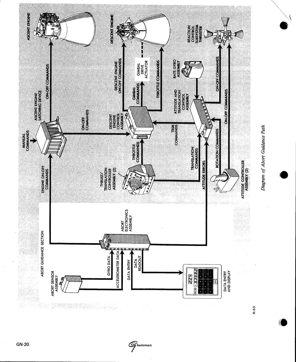
17 rb I (D / ABORT GUIDANCE SECTION The abort guidance section consists of an abort sensor assembly, a data entry and display assembly (DEDA), and an abort electronics assembly, The data entry and display assembly is commonly referred to as "the DEDA" (pronounced "deeda"). The abort sensor assembly, by means of gyros and accelerometers, provides incremental attitude information around the LM X, Y, and Z axes and incremental velocity changes along the LM X, Y, and Z axes. Data pulses are routed to the abort electronic assembly, which uses the LM attitude and velocity data for computation of steering errors. The DEDA is used by the astronauts to select the desired mode of operation, insert the desired targeting parameters, and monitor related data throughout the mission. To select a mode of operation or insert data, three digits (word address) then a plus (+) or minus (-), and finally, a five digit code must be entered. If this sequence is not followed, an operator error light goes on when the enter pushbutton is pressed. To read out any parameter, '0 three digits (address of the desired word) must be entered and a readout pushbutton pressed. The abort electronics assembly, by means of special input-output subassemblies, interfaces the abort guidance secton with the other LM subsystems and displays. This assembly is basically a general-purpose digital computer, which solves guidance and navigation problems. Mode and submode entries coupled from the data entry and display assembly determine the operation of the computer. The computer uses incremental velocity and attitude inputs from the abort sensor assembly to calculate LM position, attitude, and velocity in the inertial reference frame. It routes altitude and altitude-rate data to altitude and altitude rate indicators; out of plane velocity data, to X-pointer indicators. Also, roll, pitch and yaw steering error signals are routed to flight director altitude indicators. Engine-on commands are routed to the appropriate engine via the control electronics section when the following occur: an abort or abort stage pushbutton is pressed, appropriate switches are set, necessary data are entered into the DEDA, and velocity-to-be-gained exceeds a predetermined threshold (currently 2.1 fps). At the appropriate time, as determined by velocity-to-be-gained, an engine-off command is sent. CONTROL ELECTRONICS SECTION The control electronics section comprises two attitude controller assemblies, two thrust/ translation controller assemblies, an attitude and translation control assembly, a rate gyro assembly, descent engine control assembly, and three stabilization and control (S&C) control assemblies. The attitude controller assemblies are right-hand pistol grip controllers, which the astronauts use to command changes in LM attitude. These controllers function in a manner similar to an aircraft's "control stick". Each is installed with its longitudinal axis approximately parallel to LM X-axis; vehicle rotations correspond to astronaut hand movements. The thrust/translation controller assemblies are left-hand controllers used by the astronauts to control LM translation in any axis. Vehicle translations correspond approximately to the astronauts hand movements. The attitude and translation control assembly routes the RCS thruster on and off commands from the guidance computer to the thrusters, in the primary control mode. During abort guidance control, the assembly acts as a computer in determining which RCS thrusters are to be fired. The rate gyro assembly is used during abort guidance control to supply the attitude and translation control assembly with damping signals to limit vehicle rotation rates and to facilitate manual rate control. GN-19
18
 commands, and on and off commands to control descent engine ignition and shutdown. The S&C control assemblies are three similar assemblies.")

19 The descent engine control assembly processes engine throttling commands from the astronauts (manual control) and the guidance computer (automatic control), gimbal commands for thrust vector control, preignition (arming) commands, and on and off commands to control descent engine ignition and shutdown. The S&C control assemblies are three similar assemblies. They process, switch, and/or distribute the various signals associated with the GN&CS. LANDING RADAR The landing radar senses the velocity and altitude of the LM relative to the lunar surface by means of a three-beam Doppler velocity sensor and a single-beam radar altimeter. Velocity and range data are made available to the LM guidance computer as 15-bit binary words; forward and lateral velocity data, to the LM displays as d-c analog voltages; and range and range rate data, to the LM displays as pulse-repetition frequencies. 0

20 The landing radar consists of an antenna assembly and an electronics assembly. The antenna assembly forms, directs, transmits, and receives the four microwave beams. Two interlaced phased arrays transmit the velocity- and altimeter-beam energy. Four broadside arrays receive the reflected energy of the three velocity beams and the altimeter beam. The electronics assembly processes the Doppler and continuous-wave FM returns, which provide the velocity and slant range data for the LM guidance computer and the LM displays. The antenna assembly transmits velocity beams (10.51 ghz) and an altimeter-beam (9.58 ghz) to the lunar surface. When the electronics assembly is receiving and processing the returned microwave beams, datagood signals are sent to the LGC. When the electronics assembly is not operating properly, data-nogood signals are sent to the pulse code modulation timing electronics assembly of the Instrumentation Subsystem for telemetry. Using LM controls and indicators, the astronauts can monitor LM velocity, altitude, and radartransmitter power and temperatures; apply power to energize the radar; initiate radar self-test; and place the antenna in descent or hover position. Self-test permits operational checks of the radar without radar returns from external sources. An antenna temperature control circuit, energized at earth launch, protects antenna components against the low temperatures of space environment while the radar is not operating. The radar is first turned on and self-tested during LM checkout before separation from the CSM. The self-test circuits apply simulated Doppler signals to radar velocity sensors, and simulated lunar range signals to an altimeter sensor. The radar is self-tested again immediately before LM powered descent, approximately 70,000 feet above the lunar surface. The radar operates from approximately 50,000 feet until lunar touchdown. Altitude (derived from slant range) is available to the LGC and is displayed on a cabin indicator at approximately 25,000 feet. Slant range data are continuously updated to provide true altitude above the lunar surface. At approximately 18,000 feet, forward and lateral velocities are available to the LM guidance computer and cabin indicators. At approximately 200 feet above the lunar surface, the LM pitches to orient its X-axis perpendicular to the surface; all velocity vectors are near zero. Final visual selection of the landing site is followed by touchdown under automatic or manual control. During this phase, the astronauts monitor altitude and velocity data from the radar. R-55 Landing Radar Antenna Assembly GN-22


21 '9 %' c, I coupling data unit is initialized to accept inertial subsection data. During this period, there is a 90-second delay before power is applied to the accelerometers. This is to prevent them from torquing before the gyros reach synchronous rotor speed. ', f PRIMARY GUIDANCE PATH The primary guidance path comprises the primary guidance and navigation section, control electronics section, landing radar, and rendezvous radar and the selected propulsion section required to perform the desired maneuvers. The control electronics section routes flight control commands from the primary guidance and navigation section and applies them to the descent or ascent engine, and the appropriate thrusters. INERTIAL ALIGNMENT Inertial subsection operation can be initiated automatically by the primary guidance computer or manually by the astronaut, using DSKY entries to command the computer. The inertial subsection status or mode of operation is displayed on the DSKY as determined by a computer program. When the inertial subsection is powered up, the gimbals of the inertial measurement unit are driven to zero by a reference voltage and the The stable member of the inertial measurement unit must be aligned with respect to the reference coordinate frame each time the inertial subsection is powered up. During flight the stable member may be periodically realigned because it may deviate from its alignment, due to gyro drift. Also, the crew may desire a new stable member orientation. The alignment orientation may be that of the CSM or that defined by the thrusting programs within the computer. Inertial subsection alignment is accomplished in two steps: coarse alignment and fine alignment. To initiate coarse alignment, the astronaut selects, by a DSKY entry, a program that determines stable members orientation, and a coarse-alignment routine. The computer sends digital pulses, representing the required amount of change in gimbal angle, to the coupling data unit. The coupling data unit converts these digital pulses to analog signals which drive torque motors in the inertial measurement unit. As the gimbal angle changes, a gimbal resolver signal is applied to the coupling data unit, where it is converted to digital pulses. These digital pulses cancel the computer pulses stored in the coupling data unit. When this is accomplished, coarse alignment is completed and the astronaut can now select an in-flight fine-alignment routine. To perform the fine-alignment routine, the astronaut must use the alignment optical telescope to sight on at least two stars. The gimbals, having been coarse aligned, are relatively close to their preferred angles. The computer issues finealignment torquing signals to the inertial measurement unit after it processes star-sighting data that have been combined with known gimbal angles. Once the inertial subsection is energized and aligned, LM rotation is about the gimbaled stable member, which remains fixed in space. Resolvers mounted on the gimbal axes act as angle-sensing devices and measure attitude with respect to the GN-25

22 5f R-59 Functional Diagram of Inertial Alignment stable member. These angular measurements are displayed to the astronauts by the flight director attitude indicators, and angular changes of the inertial reference are sent to the computer. ATTITUDE CONTROL Desired attitude is calculated in the primary guidance computer and compared with the actual gimbal angles. If there is a difference between the actual and calculated angles, the inertial subsection channels of the coupling data unit generate attitude error signals, which are sent to the attitude indicators for display. These error signals are used by the digital autopilot program in the primary guidance computer to activate RCS thrusters for LM attitude correction. LM acceleration due to thrusting is sensed by three accelerometers, which are mounted on the stable member with their input axes orthogonal. The resultant signals (velocity changes) from the accelerometer loops are supplied to the computer, which calculates the total LM velocity. Two normal modes of operation achieve attitude control: automatic and attitude hold. In addition to these two modes, there is a minimum impulse mode and a four-jet manual override mode. Either of the two normal modes may be selected on the primary guidance mode control switch. In automatic mode, all navigation, guidance, and flight control is handled by the primary guidance computer. The computer calculates the desired or preferred attitude, generates the required thruster commands and routes them to the attitude and translation control assembly which fires the selected thruster. Attitude hold mode is a semiautomatic mode in which either astronaut can command attitude change at an angular rate proportional to the displacement of his attitude controller. The LM holds the new attitude when the controller is brought back to its neutral (detent) position. During primary guidance control, rate commands proportional to controller displacement are sent to GN-26
23 t ~ '@. I engine ignition after coasting phases. Manual control during primary guidance control consists of on and off commands generated by the astronaut using his thrust/translation controller. These commands are routed through the computer to the attitude and translation control assembly to fire the proper thrusters. Translation along the +X-axis can also be initiated by the astronaut using a pushbutton switch that actuates the secondary solenoid coils of the four downward firing thrusters. DESCENT ENGINE CONTROL Descent engine ignition is controlled either automatically by the primary guidance and navigation section, or manually through the control electronics section. Before ignition can occur, the engine arm switch must be set to the descent engine position. This opens the pre-valves to allow fuel and oxidizer to reach the propellant shutoff valves, arming the descent engine. Engine-on commands from either computer are routed to the descent engine control assembly which commands the descent engine on by opening 0 the propellant shutoff valves. The engine remains on until an engine-off discrete is initiated by the astronauts with either of two engine stop pushbuttons or by the computer. When the LM reaches the hover point where the lunar contact probes touch the lunar surface, a blue lunar contact light is illuminated. This indicates to the astronauts that the engine should be shut down. From this point (approximately 5 feet above the lunar surface), the LM free-falls to the lunar surface. Descent engine throttling can be controlled by the primary guidance and navigation section and/or the astronauts. Automatic increase or decrease signals from the guidance computer are sent to the descent engine control assembly. An analog output from the control assembly corresponds to the percentage of thrust desired. The engine is controllable from 10% of thrust to a maximum of 92.5%. There are two thrust control modes: automatic and manual. In the automatic mode, the astronaut can use the selected thrust/translation controller to increase descent engine thrust only. During this mode, manual commands by the astronaut are used to override the throttle commands generated by the computer. In the manual mode, the astronauts have complete control over descent engine thrust. Descent engine trim is automatically controlled during primary control, to compensate for centerof-gravity offsets due to propellant depletion and, in some cases for attitude control. The primary guidance computer routes trim commands for the pitch and roll axes. These signals drive a pair of gimbal drive actuators. These actuators, which are screwjack devices, tilt the descent engine along the Y-axis and Z-axis a maximum of +6" or-6' from the X-axis. ASCENT ENGINE CONTROL Ascent engine ignition and shutdown can be initiated automatically by the primary guidance computer or manually by the astronauts. Automatic and manual commands are routed to the S&C control assemblies. These assemblies provide logically ordered control of LM staging and engine on and off commands. A portion of the S&C control assemblies, devoted to ascent engine control, is designated as the ascent engine latching device. This device provides a positive on command for fail-safe purposes if the engine-on command is interrupted. The control assemblies are enabled " when the astronauts select the ascent engine position of the engine arm switch. In an abort stage situation while the descent engine is firing, the control assemblies provide a time delay before commanding staging and ascent engine ignition. The time delay ensures that descent engine thrusting has completely stopped before staging occurs. ABORT GUIDANCE PATH The abort guidance path comprises the abort guidance section, control electronics section, and the selected propulsion section. The abort guidance path performs all inertial guidance and navigation functions necessary to effect a safe orbit or rendezvous with the CSM. The stabilization and control functions are performed by analog computation techniques, in the control electronics section. GN-29
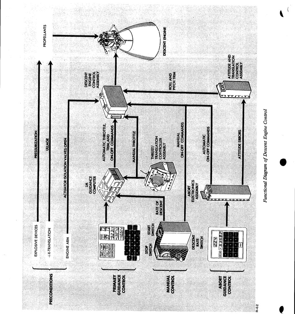
24
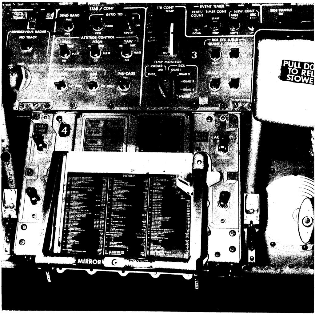
25 - ~ In addition, each of the functions has a relative priority with respect to the others; also within each there are a number of processing functions, each having a priority level relative to the other in the group. Most of the processing performed by the computer is in the program controlled processing category. During this processing the computer is controlled by the program stored in its memory. Real time, which is used in solving guidance and navigation problems, is maintained within the computer's memory. A hour (approximately 31 days) clock is provided. The clock is synchronized with ground elapsed time (GET) which is "time zero" at launch. This time is transmitted once every second by downlink operation for comparison with MSFN elapsed time. Incremental transmissions occur in the form of pulse bursts from the output channels to the coupling data unit, the gyro fine-alignment electronics, the RCS, and the radars. The number of pulses and the time at which they occur are controlled by the program. Discrete outputs, originating in the output channels under program control, are sent to the DSKY and other subsystems. A continuous pulse train at mhz originates in the timing output logic and is sent as a synchronization signal to the timing electronics assembly in the Instrumentation Subsystem (IS). The uplink word from MSFN via the digital uplink assembly is supplied as an incremental pulse to the priority control. As this word is received, priority produces the address of the uplink counter in memory and requests the sequence generator to execute the instructions that perform the serial-toparallel conversion of the input word. When the conversion is completed, the parallel word is transferred to a storage location in memory by the uplink priority program. The uplink priority program also retains the parallel word for subsequent downlink transmission. Another program converts the parallel word to a coded display format and transfers the display information to the DS KY. The downlink operation is asynchronous with respect to the IS. The IS supplies all the timing signals necessary for the downlink operation. Through the DSKY, the astronaut can load information into the computer, retrieve and display information contained in the computer, and initiate any program stored in memory. A key code is assigned to each keyboard pushbutton. When a DSKY pushbutton is pressed, the key code is sent to an input channel of the computer. A number of key codes are required to specify an address or a data word. The initiated program also converts the keyboard information to a coded display format, which is transferred by another program to an output channel and to the DSKY for display. The display is a visual indication that the key code was received, decoded, and processed properly. DISPLAY AND KEYBOARD The DSKY is located on panel 4 between the Commander and LM Pilot and above the forward hatch. The upper half is the display portion; the lower half comprises the keyboard. The display portion contains five caution indicators, six status indicators, seven operation display indicators, and three data display indicators. These displays provide visual indications of data being loaded in the computer, the computer's condition and the program being used. The displays also provide the computer with a means of displaying or requesting data. The caution indicators when on, are yellow; the status indicators, white. The operation and data displays are illuminated green when energized. The words "PROG," "VERB," and "NOUN" and the lines separating the three groups of display indicators, and the 19 pushbuttons of the keyboard are illuminated when the guidance computer is powered-up. GN-41


26 Pushbutton Function 0 through 9 Enters numerical data, noun codes, and verb codes into computer + and - Informs computer that following numerical data are decimal and indicates sign of data VERB Indicates to computer that it is going to take some action and conditions computer to interpret the next two numerical characters as a verb code NOUN Conditions computer to interpret next two numerical characters (noun code) as to what type of action is applied to verb code CLEAR Clears data contained in data display; pressing this pushbutton clears data display currently being used. Successive pressing clears other two data displays R-71 Display and Keyboard PRO KEY REL ENTR RSET Commands computer to proceed to standby mode; if in standby mode, commands computer to resume regular operation Releases keyboard displays initiated by keyboard action so that information supplied by computer program may be displayed Informs computer that data to be inserted is complete and that requested function is to be executed Turns off condition indicator lamps after condition has been corrected The DSKY enables the astronauts to insert data into the guidance computer and to initiate computer operations. The astronauts can also use the keyboard to control the moding of the inertial subsection. The exchange of data between the astronauts and the computer is usually initiated by an astronaut;. however, it can also be initiated by internal computer programs. The operator of the DSKY can communicate with the computer by pressing a sequence of pushbuttons on the DSKY keyboard. The computer can also initiate a display of information or request the operator for some action, through the processing of its program. GN-42?
27
Satellite Sub-systems
 Satellite Sub-systems Although the main purpose of communication satellites is to provide communication services, meaning that the communication sub-system is the most important sub-system of a communication
Fokker 50 - Automatic Flight Control System
 GENERAL The Automatic Flight Control System (AFCS) controls the aircraft around the pitch, roll, and yaw axes. The system consists of: Two Flight Directors (FD). Autopilot (AP). Flight Augmentation System
SELF STABILIZING PLATFORM
 SELF STABILIZING PLATFORM Shalaka Turalkar 1, Omkar Padvekar 2, Nikhil Chavan 3, Pritam Sawant 4 and Project Guide: Mr Prathamesh Indulkar 5. 1,2,3,4,5 Department of Electronics and Telecommunication,
F-104 Electronic Systems
 Information regarding the Lockheed F-104 Starfighter F-104 Electronic Systems An article published in the Zipper Magazine # 49 March-2002 Author: Country: Website: Email: Theo N.M.M. Stoelinga The Netherlands
The Apollo VHF Ranging System
 The Apollo VHF Ranging System Item Type text; Proceedings Authors Nossen, Edward J. Publisher International Foundation for Telemetering Journal International Telemetering Conference Proceedings Rights
RADIOMETRIC TRACKING. Space Navigation
 RADIOMETRIC TRACKING Space Navigation Space Navigation Elements SC orbit determination Knowledge and prediction of SC position & velocity SC flight path control Firing the attitude control thrusters to
RADIO FREQUENCY AND MODULATION SYSTEMS PART 1: EARTH STATIONS AND SPACECRAFT
 Draft Recommendations for Space Data System Standards RADIO FREQUENCY AND MODULATION SYSTEMS PART 1: EARTH STATIONS AND SPACECRAFT DRAFT RECOMMENDED STANDARD CCSDS 401.0-B-27.1 RED/PINK SHEETS August 2017
SECTION 2 BROADBAND RF CHARACTERISTICS. 2.1 Frequency bands
 SECTION 2 BROADBAND RF CHARACTERISTICS 2.1 Frequency bands 2.1.1 Use of AMS(R)S bands Note.- Categories of messages, and their relative priorities within the aeronautical mobile (R) service, are given
AVSS Project. ENAE483 Fall 2012
 AVSS Project ENAE483 Fall 2012 Team D9: Jason Burr Vera Klimchenko Grant McLaughlin Johnathan Pino Link Budget Analysis Maximum Earth-Moon Transmission Distance R M D R M R e Moon 406,700 km Earth Ku Band
RADIOMETRIC TRACKING. Space Navigation
 RADIOMETRIC TRACKING Space Navigation October 24, 2016 D. Kanipe Space Navigation Elements SC orbit determination Knowledge and prediction of SC position & velocity SC flight path control Firing the attitude
CATEGORY 7 - NAVIGATION AND AVIONICS A. SYSTEMS, EQUIPMENT AND COMPONENTS
 Commerce Control List Supplement No. 1 to Part 774 Category 7 page 1 CATEGORY 7 - NAVIGATION AND AVIONICS A. SYSTEMS, EQUIPMENT AND COMPONENTS N.B.1: For automatic pilots for underwater vehicles, see Category
OughtToPilot. Project Report of Submission PC128 to 2008 Propeller Design Contest. Jason Edelberg
 OughtToPilot Project Report of Submission PC128 to 2008 Propeller Design Contest Jason Edelberg Table of Contents Project Number.. 3 Project Description.. 4 Schematic 5 Source Code. Attached Separately
FLCS V2.1. AHRS, Autopilot, Gyro Stabilized Gimbals Control, Ground Control Station
 AHRS, Autopilot, Gyro Stabilized Gimbals Control, Ground Control Station The platform provides a high performance basis for electromechanical system control. Originally designed for autonomous aerial vehicle
Module 2: Lecture 4 Flight Control System
 26 Guidance of Missiles/NPTEL/2012/D.Ghose Module 2: Lecture 4 Flight Control System eywords. Roll, Pitch, Yaw, Lateral Autopilot, Roll Autopilot, Gain Scheduling 3.2 Flight Control System The flight control
Operating Handbook For FD PILOT SERIES AUTOPILOTS
 Operating Handbook For FD PILOT SERIES AUTOPILOTS TRUTRAK FLIGHT SYSTEMS 1500 S. Old Missouri Road Springdale, AR 72764 Ph. 479-751-0250 Fax 479-751-3397 Toll Free: 866-TRUTRAK 866-(878-8725) www.trutrakap.com
Hydroacoustic Aided Inertial Navigation System - HAIN A New Reference for DP
 Return to Session Directory Return to Session Directory Doug Phillips Failure is an Option DYNAMIC POSITIONING CONFERENCE October 9-10, 2007 Sensors Hydroacoustic Aided Inertial Navigation System - HAIN
B ==================================== C
 Satellite Space Segment Communication Frequencies Frequency Band (GHz) Band Uplink Crosslink Downlink Bandwidth ==================================== C 5.9-6.4 3.7 4.2 0.5 X 7.9-8.4 7.25-7.7575 0.5 Ku 14-14.5
Digiflight II SERIES AUTOPILOTS
 Operating Handbook For Digiflight II SERIES AUTOPILOTS TRUTRAK FLIGHT SYSTEMS 1500 S. Old Missouri Road Springdale, AR 72764 Ph. 479-751-0250 Fax 479-751-3397 Toll Free: 866-TRUTRAK 866-(878-8725) www.trutrakap.com
Part One: Presented by Matranga, North, & Ottinger Part Two: Backup for discussions and archival.
 2/24/2008 1 Go For Lunar Landing Conference, March 4-5, 2008, Tempe, AZ This Presentation is a collaboration of the following Apollo team members (Panel #1): Dean Grimm, NASA MSC LLRV/LLTV Program Manager
AN/APN-242 Color Weather & Navigation Radar
 AN/APN-242 Color Weather & Navigation Radar Form, Fit and Function Replacement for the APN-59 Radar Previous Configuration: APN-59 Antenna Stabilization Data Generator Antenna Subsystem Radar Receiver
Digiflight II SERIES AUTOPILOTS
 Operating Handbook For Digiflight II SERIES AUTOPILOTS TRUTRAK FLIGHT SYSTEMS 1500 S. Old Missouri Road Springdale, AR 72764 Ph. 479-751-0250 Fax 479-751-3397 Toll Free: 866-TRUTRAK 866-(878-8725) www.trutrakap.com
A3 Pro INSTRUCTION MANUAL. Oct 25, 2017 Revision IMPORTANT NOTES
 A3 Pro INSTRUCTION MANUAL Oct 25, 2017 Revision IMPORTANT NOTES 1. Radio controlled (R/C) models are not toys! The propellers rotate at high speed and pose potential risk. They may cause severe injury
CHAPTER 6 ENVIRONMENTAL CONDITIONS
 CHAPTER 6 ENVIRONMENTAL CONDITIONS 6.1 Summary This Chapter provides the natural environment at Xichang Satellite Launch Center (XSLC), the thermal environment during satellite processing, the thermal
GUIDED WEAPONS RADAR TESTING
 GUIDED WEAPONS RADAR TESTING by Richard H. Bryan ABSTRACT An overview of non-destructive real-time testing of missiles is discussed in this paper. This testing has become known as hardware-in-the-loop
Deep Space Communication The further you go, the harder it gets. D. Kanipe, Sept. 2013
 Deep Space Communication The further you go, the harder it gets D. Kanipe, Sept. 2013 Deep Space Communication Introduction Obstacles: enormous distances, S/C mass and power limits International Telecommunications
The Discussion of this exercise covers the following points:
 Exercise 3-2 Frequency-Modulated CW Radar EXERCISE OBJECTIVE When you have completed this exercise, you will be familiar with FM ranging using frequency-modulated continuous-wave (FM-CW) radar. DISCUSSION
INTRODUCTION. Basic operating principle Tracking radars Techniques of target detection Examples of monopulse radar systems
 Tracking Radar H.P INTRODUCTION Basic operating principle Tracking radars Techniques of target detection Examples of monopulse radar systems 2 RADAR FUNCTIONS NORMAL RADAR FUNCTIONS 1. Range (from pulse
THE GPS SATELLITE AND PAYLOAD
 THE GPS SATELLITE AND PAYLOAD Andrew Codik and Robert A. Gronlund Rockwell International Corporation Satellite Systems Division 12214 Lakewood Boulevard Downey, California, USA 90241 ABSTRACT The NAVSTAR/Global
A DUAL-RECEIVER METHOD FOR SIMULTANEOUS MEASUREMENTS OF RADOME TRANSMISSION EFFICIENCY AND BEAM DEFLECTION
 A DUAL-RECEIVER METHOD FOR SIMULTANEOUS MEASUREMENTS OF RADOME TRANSMISSION EFFICIENCY AND BEAM DEFLECTION Robert Luna MI Technologies, 4500 River Green Parkway, Suite 200 Duluth, GA 30096 rluna@mi-technologies.com
Post-Installation Checkout All GRT EFIS Models
 GRT Autopilot Post-Installation Checkout All GRT EFIS Models April 2011 Grand Rapids Technologies, Inc. 3133 Madison Avenue SE Wyoming MI 49548 616-245-7700 www.grtavionics.com Intentionally Left Blank
Sub-millimeter Wave Planar Near-field Antenna Testing
 Sub-millimeter Wave Planar Near-field Antenna Testing Daniёl Janse van Rensburg 1, Greg Hindman 2 # Nearfield Systems Inc, 1973 Magellan Drive, Torrance, CA, 952-114, USA 1 drensburg@nearfield.com 2 ghindman@nearfield.com
AE4-393: Avionics Exam Solutions
 AE4-393: Avionics Exam Solutions 2008-01-30 1. AVIONICS GENERAL a) WAAS: Wide Area Augmentation System: an air navigation aid developed by the Federal Aviation Administration to augment the Global Positioning
FPGA Implementation of Safe Mode Detection and Sun Acquisition Logic in a Satellite
 FPGA Implementation of Safe Mode Detection and Sun Acquisition Logic in a Satellite Dhanyashree T S 1, Mrs. Sangeetha B G, Mrs. Gayatri Malhotra 1 Post-graduate Student at RNSIT Bangalore India, dhanz1ec@gmail.com,
AN RF MONOPULSE ATTITUDE SENSING SYSTEM
 AN RF MONOPULSE ATTTUDE SENSNG SYSTEM J. B. TAMMES Hollandse Signaalapparaten Hengelo, The Netherlands J. J. BLEWES COMSAT Corporation Clarksburg, Maryland Summary. The application of RF monopulse sensing
Keywords. DECCA, OMEGA, VOR, INS, Integrated systems
 Keywords. DECCA, OMEGA, VOR, INS, Integrated systems 7.4 DECCA Decca is also a position-fixing hyperbolic navigation system which uses continuous waves and phase measurements to determine hyperbolic lines-of
Step vs. Servo Selecting the Best
 Step vs. Servo Selecting the Best Dan Jones Over the many years, there have been many technical papers and articles about which motor is the best. The short and sweet answer is let s talk about the application.
The Mathematics of the Stewart Platform
 The Mathematics of the Stewart Platform The Stewart Platform consists of 2 rigid frames connected by 6 variable length legs. The Base is considered to be the reference frame work, with orthogonal axes
Exam questions: AE3-295-II
 Exam questions: AE3-295-II 1. NAVIGATION SYSTEMS (30 points) In this question we consider the DME radio beacon. [a] What does the acronym DME stand for? (3 points) DME stand for Distance Measuring Equipment
TELECOMMUNICATION SATELLITE TELEMETRY TRACKING AND COMMAND SUB-SYSTEM
 TELECOMMUNICATION SATELLITE TELEMETRY TRACKING AND COMMAND SUB-SYSTEM Rodolphe Nasta Engineering Division ALCATEL ESPACE Toulouse, France ABSTRACT This paper gives an overview on Telemetry, Tracking and
Flight Detector Indicator
 Flight Detector Indicator Part No: 777-1224-003 Components Maintenance Manual No: 34-25-12 By Soumyadeep Das Raj shekhar Chatterjee Purpose of equipment: The flight detector indicator (FDI) is a part of
CubeSat Proximity Operations Demonstration (CPOD) Vehicle Avionics and Design
 Vehicle Avionics and Design") CubeSat Proximity Operations Demonstration (CPOD) Vehicle Avionics and Design August CubeSat Workshop 2015 Austin Williams VP, Space Vehicles CPOD: Big Capability in a Small Package Communications ADCS
CubeSat Proximity Operations Demonstration (CPOD) Vehicle Avionics and Design August CubeSat Workshop 2015 Austin Williams VP, Space Vehicles CPOD: Big Capability in a Small Package Communications ADCS
PART 2 - ACTUATORS. 6.0 Stepper Motors. 6.1 Principle of Operation
 6.1 Principle of Operation PART 2 - ACTUATORS 6.0 The actuator is the device that mechanically drives a dynamic system - Stepper motors are a popular type of actuators - Unlike continuous-drive actuators,
GMS-5 Telemetry and Command SubSystem 1
 GMS-5 Telemetry and Command SubSystem 1 Telemetry The telemetry subsystem consists of redundant Central Telemetry Units (CTU 1 & 2) and Remote Telemetry Units (RTU A & B) This subsystem multiplexes telemetry
Control System Design for Tricopter using Filters and PID controller
 Control System Design for Tricopter using Filters and PID controller Abstract The purpose of this paper is to present the control system design of Tricopter. We have presented the implementation of control
Active Vibration Isolation of an Unbalanced Machine Tool Spindle
 Active Vibration Isolation of an Unbalanced Machine Tool Spindle David. J. Hopkins, Paul Geraghty Lawrence Livermore National Laboratory 7000 East Ave, MS/L-792, Livermore, CA. 94550 Abstract Proper configurations
Fundamentals Of Commercial Doppler Systems
 Fundamentals Of Commercial Doppler Systems Speed, Motion and Distance Measurements I. Introduction MDT manufactures a large variety of microwave oscillators, transceivers, and other components for the
Defense Technical Information Center Compilation Part Notice
 UNCLASSIFIED Defense Technical Information Center Compilation Part Notice ADPO10954 TITLE: INS/GPS for Strike Warfare Beyond the Year 2000 DISTRIBUTION: Approved for public release, distribution unlimited
Radar observables: Target range Target angles (azimuth & elevation) Target size (radar cross section) Target speed (Doppler) Target features (imaging)
 Target size (radar cross section) Target speed (Doppler) Target features (imaging)") Fundamentals of Radar Prof. N.V.S.N. Sarma Outline 1. Definition and Principles of radar 2. Radar Frequencies 3. Radar Types and Applications 4. Radar Operation 5. Radar modes What What is is Radar? Radar?
Fundamentals of Radar Prof. N.V.S.N. Sarma Outline 1. Definition and Principles of radar 2. Radar Frequencies 3. Radar Types and Applications 4. Radar Operation 5. Radar modes What What is is Radar? Radar?
GPS System Design and Control Modeling. Chua Shyan Jin, Ronald. Assoc. Prof Gerard Leng. Aeronautical Engineering Group, NUS
 GPS System Design and Control Modeling Chua Shyan Jin, Ronald Assoc. Prof Gerard Leng Aeronautical Engineering Group, NUS Abstract A GPS system for the autonomous navigation and surveillance of an airship
RECOMMENDATION ITU-R SA (Question ITU-R 131/7) a) that telecommunications between the Earth and stations in deep space have unique requirements;
 a) that telecommunications between the Earth and stations in deep space have unique requirements;") Rec. ITU-R SA.1014 1 RECOMMENDATION ITU-R SA.1014 TELECOMMUNICATION REQUIREMENTS FOR MANNED AND UNMANNED DEEP-SPACE RESEARCH (Question ITU-R 131/7) Rec. ITU-R SA.1014 (1994) The ITU Radiocommunication
Rec. ITU-R SA.1014 1 RECOMMENDATION ITU-R SA.1014 TELECOMMUNICATION REQUIREMENTS FOR MANNED AND UNMANNED DEEP-SPACE RESEARCH (Question ITU-R 131/7) Rec. ITU-R SA.1014 (1994) The ITU Radiocommunication
SATELLITE SUBSYSTEMS. Networks and Communication Department. Dr. Marwah Ahmed
 1 SATELLITE SUBSYSTEMS Networks and Communication Department Dr. Marwah Ahmed Outlines Attitude and Orbit Control System (AOCS) Telemetry, Tracking, Command and Monitoring (TTC & M) Power System Communication
PHINS, An All-In-One Sensor for DP Applications
 DYNAMIC POSITIONING CONFERENCE September 28-30, 2004 Sensors PHINS, An All-In-One Sensor for DP Applications Yves PATUREL IXSea (Marly le Roi, France) ABSTRACT DP positioning sensors are mainly GPS receivers
Detrum GAVIN-8C Transmitter
 Motion RC Supplemental Guide for the Detrum GAVIN-8C Transmitter Version 1.0 Contents Review the Transmitter s Controls... 1 Review the Home Screen... 2 Power the Transmitter... 3 Calibrate the Transmitter...
E) all of the above E) 1.9 T
 all of the above E) 1.9 T") 1. The figure shows a uniform magnetic field that is normal to the plane of a conducting loop, which has a resistance R. Which one of the following changes will cause an induced current to flow through
1. The figure shows a uniform magnetic field that is normal to the plane of a conducting loop, which has a resistance R. Which one of the following changes will cause an induced current to flow through
ARKBIRD-Tiny Product Features:
 ARKBIRD-Tiny Product Features: ARKBIRD System is a high-accuracy autopilot designed for fixed-wing, which has capability of auto-balancing to ease the manipulation while flying. 1. Function all in one
Recent Progress in the Development of On-Board Electronics for Micro Air Vehicles
 Recent Progress in the Development of On-Board Electronics for Micro Air Vehicles Jason Plew Jason Grzywna M. C. Nechyba Jason@mil.ufl.edu number9@mil.ufl.edu Nechyba@mil.ufl.edu Machine Intelligence Lab
Hopper Spacecraft Simulator. Billy Hau and Brian Wisniewski
 Hopper Spacecraft Simulator Billy Hau and Brian Wisniewski Agenda Introduction Flight Dynamics Hardware Design Avionics Control System Future Works Introduction Mission Overview Collaboration with Penn
A Mini UAV for security environmental monitoring and surveillance: telemetry data analysis
 A Mini UAV for security environmental monitoring and surveillance: telemetry data analysis G. Belloni 2,3, M. Feroli 3, A. Ficola 1, S. Pagnottelli 1,3, P. Valigi 2 1 Department of Electronic and Information
Introduction to: Radio Navigational Aids
 Introduction to: Radio Navigational Aids 1 Lecture Topics Basic Principles Radio Directional Finding (RDF) Radio Beacons Distance Measuring Equipment (DME) Instrument Landing System (ILS) Microwave Landing
WHAT IS A CUBESAT? DragonSat-1 (1U CubeSat)
") 1 WHAT IS A CUBESAT? Miniaturized satellites classified according to height (10-30 cm) Purpose is to perform small spacecraft experiments. Use has increased due to relatively low cost DragonSat-1 (1U CubeSat)
1 WHAT IS A CUBESAT? Miniaturized satellites classified according to height (10-30 cm) Purpose is to perform small spacecraft experiments. Use has increased due to relatively low cost DragonSat-1 (1U CubeSat)
HOW TO UNDERSTAND THE WORKINGS OF RADIO CONTROL
 HOW TO UNDERSTAND THE WORKINGS OF RADIO CONTROL By: Roger Carignan This article resulted from a workshop hosted by a member of our R/C model club, the 495 th R/C Squadron. I was asked to make a presentation
Agilent 8644A-2 Air Navigation Receiver Testing with the Agilent 8644A
 Agilent 8644A-2 Air Navigation Receiver Testing with the Agilent 8644A Application Note This application note describes the synthesized internal audio source used in the Agilent Technologies 8645A, 8665A,
SPASIM: A SPACECRAFT SIMULATOR
 SPASIM: A SPACECRAFT SIMULATOR Carlos A. Liceaga NASA Langley Research Center 8 Langley Blvd., M/S 328 Hampton, VA 23681-0001 c.a.liceaga@larc.nasa.gov ABSTRACT The SPAcecraft SIMulator (SPASIM) simulates
Ch 5 Hardware Components for Automation
 Ch 5 Hardware Components for Automation Sections: 1. Sensors 2. Actuators 3. Analog-to-Digital Conversion 4. Digital-to-Analog Conversion 5. Input/Output Devices for Discrete Data Computer-Process Interface
Satellite Testing. Prepared by. A.Kaviyarasu Assistant Professor Department of Aerospace Engineering Madras Institute Of Technology Chromepet, Chennai
 Satellite Testing Prepared by A.Kaviyarasu Assistant Professor Department of Aerospace Engineering Madras Institute Of Technology Chromepet, Chennai @copyright Solar Panel Deployment Test Spacecraft operating
The Fine Guidance Sensor, An Electronic Scanning Star Tracker
 The Space Congress Proceedings 1966 (3rd) The Challenge of Space Mar 7th, 8:00 AM The Fine Guidance Sensor, An Electronic Scanning Star Tracker R. A. Deters ITT Federal Laboratories D. F. Eisenhut ITT
Communication and Navigation Systems for Aviation
 Higher National Unit Specification General information for centres Unit title: Communication and Navigation Systems for Aviation Unit code: F0M3 35 Unit purpose: This Unit is designed to allow candidates
BW-IMU200 Serials. Low-cost Inertial Measurement Unit. Technical Manual
 Serials Low-cost Inertial Measurement Unit Technical Manual Introduction As a low-cost inertial measurement sensor, the BW-IMU200 measures the attitude parameters of the motion carrier (roll angle, pitch
Set No.1. Code No: R
 Set No.1 IV B.Tech. I Semester Regular Examinations, November -2008 RADAR SYSTEMS ( Common to Electronics & Communication Engineering and Electronics & Telematics) Time: 3 hours Max Marks: 80 Answer any
Frequency-Modulated Continuous-Wave Radar (FM-CW Radar)
") Frequency-Modulated Continuous-Wave Radar (FM-CW Radar) FM-CW radar (Frequency-Modulated Continuous Wave radar = FMCW radar) is a special type of radar sensor which radiates continuous transmission power
Frequency-Modulated Continuous-Wave Radar (FM-CW Radar) FM-CW radar (Frequency-Modulated Continuous Wave radar = FMCW radar) is a special type of radar sensor which radiates continuous transmission power
A Subsidiary of Regal-Beloit Corporation. AC Inverter Terminology
 AP200-9/01 Acceleration The rate of change in velocity as a function of time. Acceleration usually refers to increasing velocity and deceleration to decreasing velocity. Acceleration Boost During acceleration,
Aerobasics An Introduction to Aeronautics
 Aerobasics An Introduction to Aeronautics 14. Air Navigation Principles S P Govinda Raju S P Govinda Raju retired as professor from the Department of Aerospace Engineering, Indian Institute of Science
Electronic Scanning Antennas Product Information
 MICROWAVE APPLICATIONS GROUP Electronic Scanning Antennas Product Information (MAG) has a proven record of creativity and innovation in microwave component and subsystem design for government, military,
Computer Numeric Control
 Computer Numeric Control TA202A 2017-18(2 nd ) Semester Prof. J. Ramkumar Department of Mechanical Engineering IIT Kanpur Computer Numeric Control A system in which actions are controlled by the direct
Frequency Synchronization in Global Satellite Communications Systems
 IEEE TRANSACTIONS ON COMMUNICATIONS, VOL. 51, NO. 3, MARCH 2003 359 Frequency Synchronization in Global Satellite Communications Systems Qingchong Liu, Member, IEEE Abstract A frequency synchronization
Glossary. Glossary Engineering Reference. 35
 Glossary Engineering Reference Glossary Abbe error The positioning error resulting from angular motion and an offset between the measuring device and the point of interest. Abbe offset The value of the
LBI-31564A. Mobile Communications. DELTA - SX MHz RADIO COMBINATIONS (NEGATIVE GROUND ONLY) Maintenance Manual
 Maintenance Manual") A Mobile Communications DELTA - SX 136-174 MHz RADIO COMBINATIONS (NEGATIVE GROUND ONLY) Maintenance Manual TABLE OF CONTENTS MILITARY AND SYSTEM SPECIFICATIONS................................. 2-3 COMBINATION
A Mobile Communications DELTA - SX 136-174 MHz RADIO COMBINATIONS (NEGATIVE GROUND ONLY) Maintenance Manual TABLE OF CONTENTS MILITARY AND SYSTEM SPECIFICATIONS................................. 2-3 COMBINATION
THE APPLICATION OF RADAR ENVIRONMENT SIMULATION TECHNOLOGY TO TELEMETRY SYSTEMS
 THE APPLICATION OF RADAR ENVIRONMENT SIMULATION TECHNOLOGY TO TELEMETRY SYSTEMS Item Type text; Proceedings Authors Kelkar, Anand; Gravelle, Luc Publisher International Foundation for Telemetering Journal
THE NASA/JPL AIRBORNE SYNTHETIC APERTURE RADAR SYSTEM. Yunling Lou, Yunjin Kim, and Jakob van Zyl
 THE NASA/JPL AIRBORNE SYNTHETIC APERTURE RADAR SYSTEM Yunling Lou, Yunjin Kim, and Jakob van Zyl Jet Propulsion Laboratory California Institute of Technology 4800 Oak Grove Drive, MS 300-243 Pasadena,
THE SHIPBOARD ANTENNA TRACKING SYSTEM OF TELEMETRY
 THE SHIPBOARD ANTENNA TRACKING SYSTEM OF TELEMETRY Gao Quan Hui Principal engineer Beijing Research Institute Of Telemetry Beijing, P. R. China ABSTRACT This paper describes a C band auto tracking receiving
ADMA. Automotive Dynamic Motion Analyzer with 1000 Hz. ADMA Applications. State of the art: ADMA GPS/Inertial System for vehicle dynamics testing
 ADMA Automotive Dynamic Motion Analyzer with 1000 Hz State of the art: ADMA GPS/Inertial System for vehicle dynamics testing ADMA Applications The strap-down technology ensures that the ADMA is stable
Massachusetts Institute of Technology. Charles Stark Draper Laboratory. Cambridge, Massachusetts. Hold or Auto Mode Control Discrete
 Massachusetts Institute of Technology Charles Stark Draper Laboratory Cambridge, Massachusetts Memo TO: FROM: DATE: SUBJECT: Russ Larson George R. Kalan 7 May 1970 LM PGNCS Software Performance with a
Implementation of Nonlinear Reconfigurable Controllers for Autonomous Unmanned Vehicles
 Implementation of Nonlinear Reconfigurable Controllers for Autonomous Unmanned Vehicles Dere Schmitz Vijayaumar Janardhan S. N. Balarishnan Department of Mechanical and Aerospace engineering and Engineering
INTRODUCTION The validity of dissertation Object of investigation Subject of investigation The purpose: of the tasks The novelty:
 INTRODUCTION The validity of dissertation. According to the federal target program "Maintenance, development and use of the GLONASS system for 2012-2020 years the following challenges were determined:
Basic Harris DX Transmitter Tutorial
 BASIC DX TUTORIAL Basic Harris DX Transmitter Tutorial Basic DX Theory The Harris DX Transmitters series, introduced in 1986, have proven to be the most efficient method of Amplitude Modulation at medium
Design and Implementation of FPGA Based Quadcopter
 Design and Implementation of FPGA Based Quadcopter G Premkumar 1 SCSVMV, Kanchipuram, Tamil Nadu, INDIA R Jayalakshmi 2 Assistant Professor, SCSVMV, Kanchipuram, Tamil Nadu, INDIA Md Akramuddin 3 Project
PERFORMANCE CONSIDERATIONS FOR PULSED ANTENNA MEASUREMENTS
 PERFORMANCE CONSIDERATIONS FOR PULSED ANTENNA MEASUREMENTS David S. Fooshe Nearfield Systems Inc., 19730 Magellan Drive Torrance, CA 90502 USA ABSTRACT Previous AMTA papers have discussed pulsed antenna
Project Bellerophon April 17, 2008
 Project Bellerophon April 17, 2008 Overview Telecommunications Flight Control Power Systems Vehicle Ground Data Processing Inputs Outputs Source Antennas Antennas Sensors Controls Supply Data Channels
Heterogeneous Control of Small Size Unmanned Aerial Vehicles
 Magyar Kutatók 10. Nemzetközi Szimpóziuma 10 th International Symposium of Hungarian Researchers on Computational Intelligence and Informatics Heterogeneous Control of Small Size Unmanned Aerial Vehicles
Challenging, innovative and fascinating
 O3b 2.4m antennas operating in California. Photo courtesy Hung Tran, O3b Networks Challenging, innovative and fascinating The satellite communications industry is challenging, innovative and fascinating.
International Journal of Scientific & Engineering Research, Volume 8, Issue 1, January ISSN
 International Journal of Scientific & Engineering Research, Volume 8, Issue 1, January-2017 500 DESIGN AND FABRICATION OF VOICE CONTROLLED UNMANNED AERIAL VEHICLE Author-Shubham Maindarkar, Co-author-
RECOMMENDATION ITU-R S.1340 *,**
 Rec. ITU-R S.1340 1 RECOMMENDATION ITU-R S.1340 *,** Sharing between feeder links the mobile-satellite service and the aeronautical radionavigation service in the Earth-to-space direction in the band 15.4-15.7
Helicopter Aerial Laser Ranging
 Helicopter Aerial Laser Ranging Håkan Sterner TopEye AB P.O.Box 1017, SE-551 11 Jönköping, Sweden 1 Introduction Measuring distances with light has been used for terrestrial surveys since the fifties.
Chapter 4 DGPS REQUIREMENTS AND EQUIPMENT SELECTION
 Chapter 4 DGPS REQUIREMENTS AND EQUIPMENT SELECTION 4.1 INTRODUCTION As discussed in the previous chapters, accurate determination of aircraft position is a strong requirement in several flight test applications
TEAM AERO-I TEAM AERO-I JOURNAL PAPER DELHI TECHNOLOGICAL UNIVERSITY Journal paper for IARC 2014
 TEAM AERO-I TEAM AERO-I JOURNAL PAPER DELHI TECHNOLOGICAL UNIVERSITY DELHI TECHNOLOGICAL UNIVERSITY Journal paper for IARC 2014 2014 IARC ABSTRACT The paper gives prominence to the technical details of
Technology Considerations for Advanced Formation Flight Systems
 Technology Considerations for Advanced Formation Flight Systems Prof. R. John Hansman MIT International Center for Air Transportation How Can Technologies Impact System Concept Need (Technology Pull) Technologies
Feedback Devices. By John Mazurkiewicz. Baldor Electric
 Feedback Devices By John Mazurkiewicz Baldor Electric Closed loop systems use feedback signals for stabilization, speed and position information. There are a variety of devices to provide this data, such
Classical Control Based Autopilot Design Using PC/104
 Classical Control Based Autopilot Design Using PC/104 Mohammed A. Elsadig, Alneelain University, Dr. Mohammed A. Hussien, Alneelain University. Abstract Many recent papers have been written in unmanned
A LARGE COMBINATION HORIZONTAL AND VERTICAL NEAR FIELD MEASUREMENT FACILITY FOR SATELLITE ANTENNA CHARACTERIZATION
 A LARGE COMBINATION HORIZONTAL AND VERTICAL NEAR FIELD MEASUREMENT FACILITY FOR SATELLITE ANTENNA CHARACTERIZATION John Demas Nearfield Systems Inc. 1330 E. 223rd Street Bldg. 524 Carson, CA 90745 USA
Gesture Identification Using Sensors Future of Interaction with Smart Phones Mr. Pratik Parmar 1 1 Department of Computer engineering, CTIDS
 Gesture Identification Using Sensors Future of Interaction with Smart Phones Mr. Pratik Parmar 1 1 Department of Computer engineering, CTIDS Abstract Over the years from entertainment to gaming market,