Wilcom MODEL T336B CIRCUIT TEST SET. Operating Instructions
|
|
|
- Gertrude Hardy
- 5 years ago
- Views:
Transcription
1 Wilcom MODEL T336B CIRCUIT TEST SET Operating Instructions
2 T336B Circuit Test Set Operating Instructions June 2005 Copyright (c) 2005 Wilcom All Rights reserved Wilcom reserves the right to make changes to the material contained herein without notice and shall not be liable for errors contained herein or for incidental, consequential damage in connection with the furnishing, performance or use of this material. This document may not be copied or duplicated in part or in whole for any purpose without the express written permission of Wilcom.
3 Contents Introduction... 1 Panel Controls and Connections... 3 Operation... 6 General Procedure... 6 Circuit Measurement Procedures... 6 Application Notes... 9 Performance Limits... 9 Measurements at the Subscriber Location... 9 Measurements at the Central Office Location.. 9 Balance Measurements... Specifications... Maintenance... Battery Replacement... Service & Repair... Warranty Figures 1. T336B Front Panel Current Measurement Plot ii
4 iii
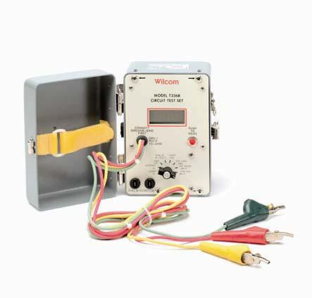
5 Introduction The Model T336B Circuit Test Set is a portable, compact, combination level and noise measuring set. It is the functional equivalent to the Wilcom T136 series of test sets, but a 3-1/2 digit LCD display replaces the analog meter. The T336B also has provisions for measuring DC resistance and voltage. Powered by two 9-volt batteries, the T336B is designed to make circuit level and noise measurements over a wide range of applications. When circuit loss, noise metallic or noise to ground are displayed, a visual indication is given if the displayed reading is over or under the accuracy range of the RMS to DC converter, the T336B measures DC volts from ring to tip lead and current from the ring lead to ground. This measurement allows evaluation of station integrity. Since the office battery potential, loop length, station ground resistance, and other variables affect the magnitude of current to ground, exact ground resistance is difficult to determine. The data pads that are used with the T336B include a table to facilitate determining if the station ground is at fault. Circuit connection is accomplished by using three 5 ft. long leads colored Green for tip, Red for ring, and Yellow for ground. These leads are permanently connected to the T336B and have universal test clips to facilitate circuit connection. 1
6 Features Wilcom MODEL T336B CIRCUIT TEST SET LO BAT CONNECT GROUND LEAD FIRST GRN-T RED-R YEL-GND PUSH TO MEAS KILOHMS dc OHMS dc DIAL & dc VOLTS GND ma LOOP ma CKT LOSS dbm CKT NOISE dbrnc PWR INFL dbrnc DIAL & MONITOR Figure 1. T336B Front Panel 2
7 Panel Controls and Connections The following describes the function and operation of the T336B panel controls, connections, and indicators (see Figure 1 on opposite page). The 3 1/2 digit LCD Display indicates measurements from to A low battery indicator (LO BAT) is located in the upper left corner. Negative readings are indicated by a minus sign that precedes the reading; positive numbers are indicated with no sign. A fixed decimal allows display accuracy at one-tenth of a unit. The PUSH TO MEAS Switch enables display of the measured level for a period of 60 seconds. The T336B circuits are activated only when you press the PUSH TO MEAS button. The PUSH TO MEAS switch has to be operated for DC current measurement. Polarity is indicated which eliminates the need for a polarity bridge. The Function Switch is an 8-position rotary switch that is used to select the desired measurement: 1. OHMS DC allows measurement of 0 to 1999 Ω using the tip (green lead) and the ring (red lead). 2. KILOHMS DC is the same as OHMS DC but with a range of 0 to 1999 kω. 3
8 Panel Controls and Connections 3.GND ma indicates the DC current drawn by a resistance of approximately 430 Ω connected between the ring lead and the station ground. A positive reading is indicated with negative battery connected to the ring lead. 4. DIAL & DC VOLTS allows connection of a headset to the line for dialing purposes. The DC VOLTS measures the typical line voltage on tip and ring at an impedance of approximately one MΩ. The DC voltage range is 0 to ±199.9V. A positive reading is indicated with negative battery connected to the ring lead. Please note that the maximum voltage rating from tip to ring is 96V AC or dc. The maximum rating from tip or ring to ground is 500V DC or 250V AC. 5. LOOP ma (dc loop current) indicates the DC current that is drawn by a DC resistance of 430ý connected across tip-to-ring. A positive reading is indicated with negative battery connected to the ring lead. 6. CKT LOSS (transmission) measurements can be taken over a level range of -55 to +5 dbm. The signal level received is terminated and the level is read directly from the LCD display. Measurements may be made at frequencies other that 1 khz as the CKT LOSS response characteristic is flat from 200 to 4000 Hz; 60 Hz is attenuated down 25 db. 4
9 Panel Controls and Connections 7. CKT NOISE (noise metallic) is measured on a C- Message weighted basis. Noise level readings on the display vary at a greater rate than those on an analog meter as it has no mechanical damping effect. The display is updated two or three times per second for noise fluctuations. 8. PWR INFL (noise-to-ground) is measured between a circuit and ground on a C-Message weighted basis. The input circuit in this position has an impedance greater than 10 MΩ dc; tip and ring are taken together to ground. The PWR INFL display is calibrated to read the noise to ground directly in dbrnc (600 Ω voltage equivalent). Dial and Monitor Connections from the front panel provide convenient locations for connecting a handset/ headset. Connections to the circuit to be tested are made with the universal clips on the 5 ft. long leads. The leads are color coded green for tip, red for ring and yellow for ground and are also marked T for tip, R for ring, and G for ground. These leads are permanently attached to the set. 5
10 Operation The following describes general operating instructions for the T336B. Also described are the procedures that you can use to make circuit measurements. General Procedure 1. Connect the test leads to the circuit under test using the green lead for tip, the red lead for ring and the yellow lead for ground. CAUTION: GROUND should be connected first. 2. Connect a handset/headset to the DIAL & MONI- TOR posts or jack. Set the function switch to DIAL & DC VOLTS. When you hear a dial tone you can then call the desired number. 3. Press the PUSH TO MEAS button each time you wish to make a measurement. Circuit Measurement Procedures OHMS DC: Circuit continuity and resistance may be checked in this position. Resistance measurements can be displayed from 0 to 1999 Ω. Refer to Specifications for display accuracy. Use the tip (green) and ring (red) leads for resistance measurements. KILOHMS DC: This function is the same as OHMS DC above but with a measurement range of 0 to 1999 kω. 6
11 Operation GND ma: This measurement is useful for evaluating station grounds. Plot this measurement on the reverse side of the Wilcom Data Reporting Pad as I (G)mA. The second measurement is LOOP ma or I(L)mA. ( See Figure 2 ) DIAL & DC VOLTS: Use this position when calling a number. Then check the line voltage after the called number answers. LOOP ma: This measurement, along with the GND ma measurement, is plotted on the reverse side of the Wilcom Data Reporting Pad. The intersection of the two points indicates the condition of station ground. CKT LOSS dbm: Dial the milliwatt generator at the central office. When the tone is received measure the level. Knowing the output level of the generator and the measured level, the circuit loss can be determined (e.g. generator output level equals 0 dbm, measured level equals -15 dbm, therefore, the CKT LOSS equals 15 db). CKT NOISE dbrnc: Dial the quiet (or balanced) termination at the central office. When the termination is received measure the noise metallic. PWR INFL dbrnc: Establish connection to a quiet (or balanced) termination. Noise to ground can now be measured. The reading is displayed directly in dbrnc, (600 Ωvoltage equivalent). 7
12 Operation Note: This chart shows acceptable readings above the curved line and unacceptable readings below the curved line. By plotting the loop current I(L)mA and the ground current I(G)mA it is possible to determine if the station ground is aceptable or not. Where the two readings intersect is the point of acceptability or unacceptability. To use the chart, first measure and plot the loop current I(L)mA, then measure and plot the ground current I(G)mA. For example; if the loop current is 35ma and the ground current is 60ma, an adequate station ground exists.if the intersection of the two measuremtns fall below the curved line then the station ground and bond should be checked. Figure 2 Current Measurement Plot 8
13 Application Notes The following describes use of the T336B in taking noise measurements at the subscriber and central office locations, and examining circuit balance. Performance Limits The measurement ranges of the T336B are designed to be within the normally acceptable limits of circuit loss, circuit noise (noise metallic) and power influence (noise to ground). Should the measured reading exceed the accuracy range of the built-in RMS to DC converter, the unused decimals and colon flash on the display. Measurements at the Subscriber Location Measurements may be made from the terminal block or protector block at the customer's location. It is not necessary to disconnect the customer's equipment, but the equipment must be in the ON HOOK condition when making measurements. The leads on the T336B are connected to the circuit using the green lead for tip, the red lead for ring and the yellow lead for ground. A good ground, preferably the ground at the protector block, must be available to make power influence measurements. Measurements at the Central Office Mainframe Noise measurements may be made at the main frame in a C.O. toward the subscriber or toward the office equipment. 9
14 Application Notes Toward Subscriber. Meaningful noise measurements can only be made toward the subscriber when there is a termination at the far end. If a section of the subscribers loop is to be measured, a termination should be connected at the far end of the section. A Wilcom Model T279 Circuit Termination Set is useful in providing such a termination. Unterminated measurements do not provide useful data for analyzing noise problems. However, if a large number of unterminated loops are tested, useful statistical information can be compiled on the extent of noise on loops out of a central office. Please note that heat coils should be removed during testing. To Central Office Equipment. To determine the level of noise that originates in the central office and the balance of the office equipment, remove the heat coils and connect the tip and ring leads to the terminals of the office equipment. Connect the ground lead to C.O. ground bus and dial the quiet termination to make CKT NOISE and PWR INFL measurements. If the induced longitudinal voltage is low, it may not be possible to make noise measurements. It is then necessary to introduce an external longitudinal voltage at a fixed frequency; any signal source between 500 and 1000 Hz is satisfactory. A Wilcom Model T137B is useful for providing a balanced terminating circuit to which a longitudinal voltage source can be connected. 10
15 Application Notes Balance Measurements Circuit balance can be determined from the CKT NOISE and PWR INFL measurements made with the T336B by using the following formula: Balance (db) = PWR INFL (dbrnc) - CKT NOISE (dbrnc) The balance of a circuit determines how sensitive it is to the induction of noise. The following values provide a guide for determining acceptable balance: Balance Condition Over 60 db Excellent db Good db Fair Under 40 db Poor Typically, any balance under 50 db requires improvement, particularly when the power influence is high, i.e., over 75 dbrnc as measured on the T336B. If power influence is low, a greater degree of imbalance can be tolerated. However, if the power influence should increase, the practice is to get as high a balance as possible. 11
16 Specifications Manufacturer Models Name Operational Ranges OHMS DC: KILOHMS DC: GND ma: dc VOLTS: LOOP ma: CKT LOSS: CKT NOISE: PWR INFL: Wilcom T336B Circuit Test Set 0 to 1999 Ω, 1Ω resolution 0 to 1999 kω, 1kΩ resolution 0 to ±199.9 ma DC (0.1 ma resolution) in 430 Ω 0 to V DC (0.1V resolution), across 1 mω resistance 0 to ±199.9 ma DC (0.1 ma resolution) in 430 Ω -55 to +5 dbm, 0.1 db resolution in 600 Ω 0 to 60 dbrnc in 600 Ω, 0.1 db resolution 50 to 110 dbrnc, 0.1 db resolution 12
17 Specifications Accuracy 25 C): OHMS DC: 400 to 1000 Ω ; ±1% Other readings: ±2% + 2Ω KILOHMS DC: ±3% + 2 kω dc Volts: ±2% + 0.2V GND ma at 20 ma: ±0.2 ma Other readings: ±2% ma LOOP ma at 20 ma: ±0.2 ma Other readings: ±2% ma CKT LOSS (w/ 1004 Hz tone): CKT NOISE (w/ 1004 Hz tone): PWR INFL: ±0.1 db from -10 to 0 dbm ±0.2 db from -40 to +5 dbm ±0.3 db from -55 to -40 dbm ±0.3 db at 30 dbrnc ±0.5 db from 20 to 60 dbrnc ±1.0 db from 0 to 20 dbrnc ±0.5 db from 70 to 110 dbrnc ±1.0 db from 50 to 70 dbrnc 13
18 Specifications Change w/ temp relative to 25ºC: dc measurements: ±1% max, -20º to 50ºC LOSS and NOISE measurements: ±0.2 db max. at 0º to 50ºC ±0.5 db max. at -20ºC Frequency Response CKT LOSS: 4 khz: Flat within accuracy specs 200 Hz to 400 Hz: ±0.5 db relative to 1004 Hz 4 khz to 15 khz: ±0.5 db relative to 1004 Hz 60 Hz down at least 20 db relative to 1004 Hz CKT NOISE: PWR INFLUENCE: Input Impedance OHMS DC: C-Message Weighting C-Message Weighting High resistance 1 ma current source KILOHMS DC: High resistance 1µA current source GND ma: 430Ω ±1% DC ring-to-ground; tip open-circuit 14
19 DIAL & DC VOLTS: Specifications Tip and Ring directly connected to DIAL & MONITOR terminals, 1 MΩ shunt Other FUNCTION Positions: Tip-to-Ring: Return loss: Tip-Ring to GND: Miscellaneous Monitor Output: Push to Measure: Detector: 430Ω ±1% dc, 600Ω ac >30 db with respect to 600 Ω 200 Hz to 15 khz >10 MΩ dc, >100 kω AC Balanced 600 Ω output, approx. 0.25V at center of each autorange. At DIAL & MONITOR terminals during CKT LOSS, CKT NOISE, and PWR INFL measurement. Push button ON Auto-off after approx. 60 sec. True rms Longitudinal Balance: >100 db at 100 Hz, decreasing 20 db/decade at higher freq. Digital Readout Response: Approx. 1 second for 10 db level change. Two or three updates/ second for noise fluctuations. 15
20 Specifications Tip or Ring to GND: Maximum Ratings Tip-to-Ring: Power Batteries: DC: 500V, AC: 250V AC to DC, 96V applied through 400 Ω Two 9V NEDA 1604 or1604a Battery Life: 30 hours continuous, or 1800 operations of the PUSH TO MEAS switch. Environmental Operating: Operating Temp.: Humidity: Altitude: Storage Temp.: -20 to +50 C 90% at 35 C, C to 5000 meters -50 to +70 C Physical Width: 4-3/8 in. (11.0 cm) Height: 6-3/8 in. (16.0 cm) Depth: 4-7/8 in. (12.5 cm) Weight: 2.9 lbs. (1.3 kg) 16
21 Maintenance Battery Replacement To replace the two 9-volt batteries, remove the unit from the case by loosening the four screws that are indicated with arrows on the panel (Figure 1). The batteries can then be easily replaced. CAUTION: To prevent possible circuit malfunction, power off the unit before removing the batteries. 17
22 Service and Repair For service or repair follow the procedure below: 1. Call Wilcom Customer Service. Support personnel will determine if the equipment requires service, repair or calibration. 2. If the equipment must be returned to Wilcom for service, Wilcom Customer Service will issue a Return Material Authorization (RMA) number and the following address for return: Wilcom 73 Daniel Webster Highway Belmont, NH TEL (800) (USA only) or (603) FAX (603) IMPORTANT Never send any equipment back to Wilcom without a Return Material Authorization (RMA) number. 3. Pack the equipment in its original shipping material. Be sure to include a statement or report fully detailing the defect and conditions under which it was observed. 18
23 Service and Repair Also be sure to include a contact name and telephone number. 4. Return the equipment, prepaid, to the above address. Be sure to write the RMA on the shipping slip. Wilcom will refuse and return any package that does not bear the RMA. Ordering Information Orders for any of the Wilcom products and any of their optional accessories should be directed to the address shown above. 19
24 WARRANTY All products are warranted against defects in materials and workmanship. This warranty applies for a period of two (2) years from date of delivery, except for Fiber Optic instrumentation and equipment which have a one (1) year warranty on parts and two (2) years on labor. (The only exception in the digital testing equipment is the D550 Shark, which has a warranty of one (1) year from date of delivery.) Wilcom's obligation under this warranty is limited to servicing or adjusting each instrument returned to its factory within the warranty period, and to replace any components found to be defective. If determined that the defective condition is a result of misuse or abnormal operation, repairs will be billed. LIMITATION OF WARRANTY The foregoing warranties are the exclusive warranties provided by Wilcom. Wilcom will not be liable for any special, indirect, incidental or consequential damages whatsoever resulting from loss of use, loss of data or loss of profits arising out of or in connection with the use or performance of the product, even if Wilcom has been informed of the possibility of such damages in advance. All implied warranties, including without limitation warranties of merchantability and fitness for a particular purpose, as well as warranties arising from a course of dealing or usage of trade are expressly disclaimed. PROPRIETARY INFORMATION The information contained in this manual is the proprietary material of Wilcom, and may not be reproduced, used for manufacturing purposes, or disclosed to others 20
Wilcom MODEL T136BSBZW CIRCUIT TEST SET. Operating Instructions
 Wilcom MODEL T136BSBZW CIRCUIT TEST SET Operating Instructions T136BSB Current Test Set Operating Instructions 811-230-007 February 2007 Copyright (c) 2007 Wilcom All Rights reserved Wilcom reserves the
Wilcom MODEL T136BGMZW CIRCUIT TEST SET. Operating Instructions
 Wilcom MODEL T136BGMZW CIRCUIT TEST SET Operating Instructions T136BGM Current Test Set Operating Instructions 811-233-010 February 2007 Copyright (c) 2007 Wilcom All Rights reserved Wilcom reserves the
Wilcom. T-304B Current Meter OPERATING INSTRUCTIONS
 Wilcom T-304B Current Meter OPERATING INSTRUCTIONS T-304B Current Meter Operating Instructions 811-434-009 March 2007 Copyright (c) 2007 Wilcom All Rights reserved Wilcom reserves the right to make changes
User s Guide. 400A AC/DC Clamp Meter. Model MA220
 User s Guide 400A AC/DC Clamp Meter Model MA220 Introduction Thank you for selecting the Extech MA200 AC/DC Clamp Meter. This meter measures AC/DC Current, AC/DC Voltage, Resistance, Capacitance, Frequency,
SX204. Headphone Amplifier. Symetrix. Owner s Manual
 Symetrix SX204 Headphone Amplifier Owner s Manual Symetrix Inc. 14926 35th Avenue West Lynnwood, Washington 98037 Voice: (206) 787-3222, (800) 288-8855 Fax: (206) 787-3211 Copyright 1988, 1994 Symetrix
User Guide. Digital AC/DC Clamp Meter Model 38394
 User Guide Digital AC/DC Clamp Meter Model 38394 Introduction Congratulations on your purchase of Extech s 38394 AC/DC Clamp Meter. This clamp meter measures AC/DC Current to 600A, DC/AC Voltage, Resistance,
User s Guide. Digital AC/DC Clamp Meter Model 38394
 User s Guide Digital AC/DC Clamp Meter Model 38394 Introduction Congratulations on your purchase of Extech s 38394 AC/DC Clamp Meter. This clamp meter measures AC/DC Current to 600A, DC/AC Voltage, Resistance,
INSTRUCTION MANUAL. Model Autoranging DMM ProbeMeter TM. Measures voltage, resistance, frequency, capacitance, temperature, and duty cycle.
 INSTRUCTION MANUAL Model 403380 Autoranging DMM ProbeMeter TM Measures voltage, resistance, frequency, capacitance, temperature, and duty cycle. Back lit LCD with Autorange and full function displays Audible
Safety. This symbol, adjacent to a terminal, indicates that, under normal use, hazardous voltages may be present.
 9305 Safety International Safety Symbols This symbol, adjacent to another symbol or terminal, indicates the user must refer to the manual for further information. This symbol, adjacent to a terminal, indicates
Pen Multimeter. Model
 Pen Multimeter Model 381626 CAUTION: Read, understand and follow all Safety Rules and Operating Instructions in this manual before using this product. This instrument is a 3200 count pen style digital
Pen Multimeter. Model
 Pen Multimeter Model 381626 CAUTION: Read, understand and follow all Safety Rules and Operating Instructions in this manual before using this product. This instrument is a 3200 count pen style digital
User s Manual. MiniTec TM Series. Model MN26 (Model MN26T includes temperature probe) Mini Autoranging MultiMeter
 Mini Autoranging MultiMeter") User s Manual MiniTec TM Series Model MN26 (Model MN26T includes temperature probe) Mini Autoranging MultiMeter Introduction Congratulations on your purchase of Extech s MN26 Autoranging Multimeter. This
User s Manual MiniTec TM Series Model MN26 (Model MN26T includes temperature probe) Mini Autoranging MultiMeter Introduction Congratulations on your purchase of Extech s MN26 Autoranging Multimeter. This
HHMA2 DC / TRUE RMS AC NON-CONTACT MILLIAMMETER
 HHMA2 DC / TRUE RMS AC NON-CONTACT MILLIAMMETER Instruction Manual Manual UN-01-249 Item 359934 April, 1999 Rev. -- OMEGA Engineering Inc. All rights reserved. This symbol appears on the instrument and
Dawson DDM190. Digital Multimeter User s Manual
 Dawson DDM190 Digital Multimeter User s Manual TABLE OF CONTENTS LIMITED WARRANTY AND LIMITATION OF LIABILITY... 3 Out of the Box... 3 Accessories.. Error! Bookmark not defined. Safety Information... 7
3M Dynatel Far End Device III
 3M Dynatel Far End Device III User s Guide PAIR 1 GND CO PAIR 2 F1 F2 STATUS Dynatel Far End Device III 1 1/2 0 Future-Proof Testing Platform February 2009 78-8140-2657-7-A 3 2 3M Dynatel Far End Device
User s Guide. MultiView Series Digital MultiMeters Models: MV110 MV120 MV130
 User s Guide MultiView Series Digital MultiMeters Models: MV110 MV120 MV130 WARRANTY EXTECH INSTRUMENTS CORPORATION warrants this instrument to be free of defects in parts and workmanship for one year
Classic Series Public Address Amplifiers C10 & C20 Models
 Classic Series Public Address Amplifiers C10 & C20 Models Installation and Use Manual 2009 Bogen Communications, Inc. All rights reserved. Specifications subject to change without notice. 54-5978-01B 0901
AM-510 Commercial / Residential Multimeter. AM-510-EUR Digital Multimeter. Users Manual
 AM-510 Commercial / Residential Multimeter AM-510-EUR Digital Multimeter Users Manual AM-510 Commercial / Residential Multimeter AM-510-EUR Digital Multimeter English Users Manual Limited Warranty and
Angular Rate Sensor. Owner's Manual
 Angular Rate Sensor Owner's Manual Part Number: ARS-C132-1A WATSON INDUSTRIES, INC. 3041 MELBY ROAD EAU CLAIRE, WI 54703 Phone: (715) 839-0628 FAX: (715) 839-8248 email: support@watson-gyro.com 1 Table
Far End Device II Model 1342
 3 Far End Device II Model 1342 Operating Instructions Optimized for ADSL2+ May 2007 78-8130-0876-6-C Table of Contents Introduction...3 Power-up...4 Connecting the 3M Far End Device II...5 Installing,
DA208 & DA416 DISTRIBUTION AMPLIFIERS OPERATING AND MAINTENANCE MANUAL
 DA208 & DA416 DISTRIBUTION AMPLIFIERS OPERATING AND MAINTENANCE MANUAL Copyright 2011, ATI Audio Inc. DESCRIPTION Your DA208 or DA416 provides two (DA208) or four (DA416) independent one-in by four-out
CM605. User Manual AC/DC LOW CURRENT CLAMP-ON METER ENGLISH
 AC/DC LOW CURRENT CLAMP-ON METER CM605 ENGLISH User Manual Statement of Compliance Chauvin Arnoux, Inc. d.b.a. AEMC Instruments certifies that this instrument has been calibrated using standards and instruments
200Amp AC Clamp Meter + NCV Model MA250
 User's Guide 200Amp AC Clamp Meter + NCV Model MA250 Introduction Congratulations on your purchase of this Extech MA250 Clamp Meter. This meter measures AC Current, AC/DC Voltage, Resistance, Capacitance,
TIA-527 Balanced Optical/Electrical Converter. Operating Instructions
 TIA-527 Balanced Optical/Electrical Converter Operating Instructions Terahertz Technologies Inc.169 Clear Road Oriskany NY 13424 (315) 736-3642 FAX (315) 736-4078 E-mail sales@terahertztechnologies.com
TRANSDUCER IN-LINE AMPLIFIER
 TRANSDUCER IN-LINE Voltage Model AMPLIFIER 2080 Arlingate, Columbus, Ohio 43228, (614) 850-5000 Sensotec, Inc. 2080 Arlingate Lane Columbus, Ohio 43228 Copyright 1995 by Sensotec, Inc. all rights reserved
DIGITAL SOUND LEVEL DSM8930 METER USER S MANUAL. Please read this manual carefully and thoroughly before using this product.
 DIGITAL SOUND LEVEL METER USER S MANUAL DSM8930 Please read this manual carefully and thoroughly before using this product. TABLE OF CONTENTS Introduction.............................. 2 3 Key Features................................
MICROTOOLS MICRONETBLINK KIT
 MICROTOOLS MICRONETBLINK KIT MicroNetBlink TM MicroProbe TM User Guide Manuel Utilisateur Benutzer Handbuch Manuale per l'utente Guía del Usuario Manual do Utilizador 2947-4511-01 Rev. 01 11/01 2001 Fluke
2001A. 200KHz Function Generator Instruction Manual. 99 Washington Street Melrose, MA Phone Toll Free
 2001A 200KHz Function Generator Instruction Manual 99 Washington Street Melrose, MA 02176 Phone 781-665-1400 Toll Free 1-800-517-8431 Visit us at www.testequipmentdepot.com WARRANTY Global Specialties
SI-125 Power Amplifier Manual 6205 Kestrel Road; Mississauga, Ontario; Canada; L5T 2A1 November 2016, Rev 0.5
 SI-125 Power Amplifier Manual 6205 Kestrel Road; Mississauga, Ontario; Canada; L5T 2A1 November 2016, Rev 0.5 Phone: (905) 564-0801 Fax: (905) 564-0806 www.telecor.com E:\T2-108\T2-M108-ABC\T2-M108-B.doc/AD
User s Manual. Ground Resistance Clamp On Tester MODEL
 User s Manual Ground Resistance Clamp On Tester MODEL 382357 Warranty EXTECH INSTRUMENTS CORPORATION warrants the basic instrument to be free of defects in parts and workmanship for one year from date
99 Washington Street Melrose, MA Fax TestEquipmentDepot.com # # AAC Clamp Meter. Instruction Manual
 99 Washington Street Melrose, MA 02176 Fax 781-665-0780 TestEquipmentDepot.com #61-732 #61-736 400 AAC Clamp Meter Instruction Manual AC HOLD APO DC KMΩ mva WARNING Read First: Safety Information Understand
Model 7000 Low Noise Differential Preamplifier
 Model 7000 Low Noise Differential Preamplifier Operating Manual Service and Warranty Krohn-Hite Instruments are designed and manufactured in accordance with sound engineering practices and should give
User s Guide. Model MA A AC Mini Clamp-on Meter
 User s Guide Model MA150 200A AC Mini Clamp-on Meter Introduction Congratulations on your purchase of Extech s MA150 AC Mini Clamp Meter. This meter is shipped fully tested and calibrated and, with proper
80i-600A AC Current Probe
 x Instruction Sheet 80i-600A AC Current Probe INTRODUCTION The Model 80i-600A is a clamp-on ac current probe designed to extend the current measuring capability of an ac current meter to 600 amperes. A
Dawson DDM181. Pocket-Size Autorange Digital Meter User s Manual
 Dawson DDM181 Pocket-Size Autorange Digital Meter User s Manual 1 Table of Contents LIMITED WARRANTY AND LIMITATION OF LIABILITY... 3 Out of the Box... 3 Accessories... 4 Important Safety Information...
DL102 Counter Loop Amplifier
 DL102 Counter Loop Amplifier USER MANUAL MAN 234A Contents Overview...3 System Includes...3 Maintenance and Recycling Instructions...3 Safety Information...4 Quick Setup...5 Setup...6 Loop Amplifier...6
User's Guide Mini Multimeter with Non-Contact Voltage Detector (NCV) Model EX330
 Model EX330") User's Guide Mini Multimeter with Non-Contact Voltage Detector (NCV) Model EX330 Introduction Congratulations on your purchase of the Extech EX330 Meter. The EX330 offers AC/DC Voltage, AC/DC Current,
User's Guide Mini Multimeter with Non-Contact Voltage Detector (NCV) Model EX330 Introduction Congratulations on your purchase of the Extech EX330 Meter. The EX330 offers AC/DC Voltage, AC/DC Current,
Dawson DDM230C. True RMS Multimeter with Bar Graph Display User s Manual
 Dawson DDM230C True RMS Multimeter with Bar Graph Display User s Manual Table of Contents LIMITED WARRANTY AND LIMITATION OF LIABILITY... 3 Out of the Box... 3 Accessories... 4 Safety Information... 4
Autoranging Multimeter Extech EX503
 User's Guide Autoranging Multimeter Extech EX503 Introduction Congratulations on your purchase of the Extech EX503 Autoranging Multimeter. This meter measures AC/DC Voltage, AC/DC Current, Resistance,
1000A AC DIGITAL CLAMPMETER MODEL KM 3060
 An ISO 9001:2008 Company 1000A AC DIGITAL CLAMPMETER MODEL KM 3060 GENERAL SPECIFICATIONS : í AC Current : 0.01A ~ 1000A í AC Voltage : 1V ~ 750V í DC Voltage : 1V ~ 1000V í Resistance : 0.1W ~ 2MW í Frequency
TRANSDUCER IN-LINE AMPLIFIER
 TRANSDUCER IN-LINE Bi-Polar Model AMPLIFIER 2080 Arlingate Lane, Columbus, Ohio 43228 (614) 850-5000 Sensotec, Inc. 2080 Arlingate Lane Columbus, Ohio 43228 Copyright 1995 by Sensotec, Inc. all rights
TLS-3A. Telephone Line Simulator. User Manual , Rev. B Covers Model TLS-3A-01
 User Manual TLS-3A Telephone Line Simulator 40-400-00010, Rev. B Covers Model TLS-3A-01 Teltone Corporation 22121-20th Avenue SE Bothell, Washington 98021-4408 USA Phone: 1-800-426-3926 or 425-487-1515
R-X SERIES. Decade Resistor
 PRECISION INSTRUMENTS FOR TEST AND MEASUREMENT R-X SERIES Decade Resistor User and Service Manual Effectivity: Serial Numbers beginning with P2 RX im/august, 2002 Copyright 2002 IET Labs, Inc. IET LABS,
ADA416-XLR DISTRIBUTION AMPLIFIERS OPERATING AND MAINTENANCE MANUAL
 ADA416-XLR DISTRIBUTION AMPLIFIERS OPERATING AND MAINTENANCE MANUAL Copyright 2015, ATI Audio Inc. DESCRIPTION Your ADA416-XLR provides four independent one-in by four-out circuit groups. A four-output
DM-46 Instruction Manual
 Auto Meter Products Inc. Test Equipment DM-46 Instruction Manual Automotive Multimeter and Inductive Amp Probe The DM-46 is the auto industry s answer to pocket portability in a 20 2650-1552-00 3/8/11
742A Series Resistance Standards
 742A Series Resistance Standards Instruction Manual PN 850255 September 1988 Rev. 1, 4/89 1988-2015 Fluke Corporation. All rights reserved. All product names are trademarks of their respective companies.
305 Stimulus Isolator. Description
 Description The Model 305 Stimulus Isolator utilizes photon coupling to provide nearly ideal isolation of the pulse and train outputs of the WPI Series 300 Anapulse Stimulators. Two Model 305 units are
Instruction Manual Model M Switch, DPDT, Manual Select
 Instruction Manual Model 1582-70M Switch, DPDT, Manual Select November 2018 Rev 0 STATUS MODEL 1582 CROSS TECHNOLOGIES INC. MANUAL SELECT POWER Data, drawings, and other material contained herein are proprietary
USER'S MANUAL DMR-2400
 USER'S MANUAL DIGITAL MULTIMETER DMR-2400 CIRCUIT-TEST ELECTRONICS www.circuittest.com TABLE OF CONTENTS SAFETY Safety Information...................................... 2 Safety Symbols........................................
34134A AC/DC DMM Current Probe. User s Guide. Publication number April 2009
 User s Guide Publication number 34134-90001 April 2009 For Safety information, Warranties, Regulatory information, and publishing information, see the pages at the back of this book. Copyright Agilent
USER'S MANUAL DMR-6700
 USER'S MANUAL Multimeter True RMS DMR-6700 CIRCUIT-TEST ELECTRONICS www.circuittest.com Introduction This meter measures AC/DC Voltage, AC/DC Current, Resistance, Capacitance, Frequency (electrical & electronic),
MS8250A/B OPERATION MANUAL MS8250A. Hz% FUNC REL RANGE REL HOLD OFF 10A. Hz% A NCV. Hz% COM. A ma 10A FUSED 600V CAT IV.
 MS8250A/B DIGITAL MULTIMETER OPERATION MANUAL AUTO DC AC REL hfe PCLINK % C F kmωkz nµmfav MS8250A DIGITAL MULTIMETER Auto Power Off RANGE REL HOLD FUNC NCV A ma OFF 10A A ma 10A FUSED 600V CAT IV COM
This manual should be read in its entirety prior to operation of the TS200 Test Set Page 2 of 9
 DUKANE CORPORATION SEACOM DIVISION TECHNICAL MANUAL ULTRASONIC TEST SET MODEL TS200 April 20, 2001 REV 00 DUKANE CORPORATION ST. CHARLES, ILLINOIS 60174 PHONE: 630-584-2300 FAX: 630-584-5154 DOCUMENT NO.
TIA-4000 Optical/Electrical Converter. Operating Instructions
 TIA-4000 Optical/Electrical Converter Operating Instructions Terahertz Technologies Inc.169 Clear Road Oriskany NY 13424 (315) 736-3642 FAX (315) 736-4078 E-mail sales@terahertztechnologies.com 10/2014
DCM730. Digital Clamp Meter User s Manual
 DCM730 Digital Clamp Meter User s Manual Table of Contents LIMITED WARRANTY AND LIMITATION OF LIABILITY...1 Out of the Box...1 Safety Information...2 INTRODUCTION...4 Components and Buttons...6 Names of
Series 3000 Model R-107A
 Series 3000 Model R-107A DUAL TONE SENDER INSTRUCTION MANUAL Monroe Electronics 100 Housel Ave Lyndonville NY 14098 800-821-6001 585-765-2254 fax 585-765-9330 monroe-electronics.com Printed in USA Copyright
Classic Series Public Address Amplifiers C10 & C20 Models
 Classic Series Public Address Amplifiers C10 & C20 Models Installation and Use Manual 2009 Bogen Communications, Inc. All rights reserved. Specifications subject to change without notice. 54-5978-01C 1106
UNCONTROLLED WHEN PRINTED
 TECHNICAL MANUAL ULTRASONIC TEST SET MODEL TS500 MAY 22, 2017 REV A DUKANE SEACOM, INC. SARASOTA, FLORIDA 34243 PHONE: 941-741-3200 FAX: 941-739-3201 DOCUMENT NO. 03-TM-0082 DUKANE SEACOM, INC. INTERNET:
Model 935A Current Source Operation Manual
 Model 935A Current Source Operation Manual Arbiter Systems, Inc. Paso Robles, CA 93446 U.S.A. ii Description This manual is issued for reference only, at the convenience of Arbiter Systems. Reasonable
36 AC/DC True RMS. Clamp Meter. P Read First: Safety Information
 36 / True RMS Clamp Meter Instruction Sheet P Read First: Safety Information To ensure safe operation and service of the meter, follow these instructions: Avoid working alone so assistance can be rendered.
DDM350 Pen-Type Digital Multimeter User s Manual
 DDM350 Pen-Type Digital Multimeter User s Manual CONTENTS LIMITED WARRANTY AND LIMITATION OF LIABILITY....1 Out of the Box...1 Accessories......2 Safety Information...2 Safety Symbols...3 Certification......4
3 Tone Slope FINAL TEST using manual meter mode process 5 Point Test and COT Assistance
 3 Tone Slope FINAL TEST using manual meter mode process 5 Point Test and COT Assistance These test results will not be captured in the EXP manager, but are the minimum requirements to close a ticket or
CT-2 and CT-3 Channel Taggers OPERATION MANUAL
 CT-2 and CT-3 Channel Taggers OPERATION MANUAL Trilithic Company Profile Trilithic is a privately held manufacturer founded in 1986 as an engineering and assembly company that built and designed customer-directed
AM-500 Autoranging Mulitmeter. AM-500-EUR Digital Multimeter. Users Manual
 AM-500 Autoranging Mulitmeter AM-500-EUR Digital Multimeter Users Manual AM-500 Autoranging Mulitmeter AM-500-EUR Digital Multimeter English Users Manual 8/2012, 4275548 A 2012 Amprobe Test Tools. All
MBC Bipolar Microstep Driver. User s Guide E. Landon Drive Anaheim, CA
 MBC10641 Bipolar Microstep Driver User s Guide A N A H E I M A U T O M A T I O N 4985 E. Landon Drive Anaheim, CA 92807 e-mail: info@anaheimautomation.com (714) 992-6990 fax: (714) 992-0471 website: www.anaheimautomation.com
AC68C. Users Manual. True RMS AC/DC Clamp Multimeter. PN July Amprobe Test Tools. All rights reserved.
 AC68C True RMS AC/DC Clamp Multimeter Users Manual PN 2729051 July 2006 2006 Amprobe Test Tools. All rights reserved. Printed in Taiwan For detailed specifications and ordering info go to www.testequipmentdepot.com
TIA-3000 Optical/Electrical Converter. Operating Instructions
 TIA-3000 Optical/Electrical Converter Operating Instructions Terahertz Technologies Inc.169 Clear Road Oriskany NY 13424 (315) 736-3642 FAX (315) 736-4078 E-mail sales@terahertztechnologies.com 6/2011
True RMS AC / DC Power Clamp Meter Model
 User's Guide True RMS AC / DC Power Clamp Meter Model 380940 Warranty EXTECH INSTRUMENTS CORPORATION warrants this instrument to be free of defects in parts and workmanship for one year from date of shipment
PEN TYPE DIGITAL MULTIMETER OPERATION MANUAL T8211D
 PEN TYPE DIGITAL MULTIMETER OPERATION MANUAL T8211D T8211D 1 1. SAFETY INFORMATION BE EXTREMELY CAREFUL IN THE USE OF THIS METER. Improper use of this device can result in electric shock or destroy of
12B/18 MultiMeter Instruction Sheet
 12B/18 MultiMeter Instruction Sheet P Read First: Safety Information To ensure that the meter is used safely, follow these instructions: Do not use the meter if the meter or test leads appear damaged,
IDEAL INDUSTRIES, INC. TECHNICAL MANUAL MODEL: MODEL: Multimeter Service Information
 IDEAL INDUSTRIES, INC. TECHNICAL MANUAL MODEL: 61-340 MODEL: 61-342 Multimeter Service Information The Service Information provides the following information: Precautions and safety information Specifications
DA560D COMPACT SERIES. INSTALLATION / OWNER'S MANUAL Mobile Power Amplifiers
 DA560D COMPACT SERIES INSTALLATION / OWNER'S MANUAL Mobile Power Amplifiers Preparation Please read entire manual before installation. Due to the technical nature of amplifiers, it is highly recommended
TIA-952 Optical/Electrical Converter. Operating Instructions
 TIA-952 Optical/Electrical Converter Operating Instructions Terahertz Technologies Inc.169 Clear Road Oriskany NY 13424 (315) 736-3642 FAX (315) 736-4078 E-mail sales@terahertztechnologies.com 2/2012 Contents
TIA-500 Optical/Electrical Converter Operating Instructions
 TIA-500 Optical/Electrical Converter Operating Instructions Terahertz Technologies Inc.169 Clear Road Oriskany NY 13424 (315) 736-3642 FAX (315) 736-4078 E-mail sales@terahertztechnologies.com Contents
Glass Electrode Meter
 Glass Electrode Meter INSTRUCTION MANUAL FOR Glass Electrode R/C Meter MODEL 2700 Serial # Date PO Box 850 Carlsborg, WA 98324 U.S.A. 360-683-8300 800-426-1306 FAX: 360-683-3525 http://www.a-msystems.com
Passive Component LCR Meter
 User's Guide Passive Component LCR Meter Model 380193 LCR M eter 380193 APO AUTO c PAL D 1kHz µ F -0 ENTER L/C/R Q/D/R 1 2 3 RANGE L/C/R Q/D/R 4 5 6 >2sec HOLD MIN MAX SET 7 8 9 REL Hi / Lo LIMITS TOL
Process Calibrator. TechChek 820
 Process Calibrator TechChek 80 CONTENTS GENERAL... TURN ON... CONNECTIONS... TILT STAND...4 CHANGING BATTERIES...4 RESTORING DEFAULT SETTINGS... CONFIGURING TEMPERATURE SCALES... ENABLING AUTO-OFF... SELECTING
600A Clamp Meters w/tightsight Display
 V 750V #61-764 #61-766 #61-768 600A Clamp Meters w/tightsight Display Instruction Manual 99 Washington Street Melrose, MA 02176 Fax 781-665-0780 TestEquipmentDepot.com CAT.IV 600V CAT.III 1000V 600A 61-766
Advanced Test Equipment Rentals ATEC (2832)
") Established 1981 Advanced Test Equipment Rentals www.atecorp.com 800-404-ATEC (2832) A.H. Systems Model Active Monopole Antennas Active Monopole Antenna Series Operation Manual 1 TABLE OF CONTENTS INTRODUCTION
Established 1981 Advanced Test Equipment Rentals www.atecorp.com 800-404-ATEC (2832) A.H. Systems Model Active Monopole Antennas Active Monopole Antenna Series Operation Manual 1 TABLE OF CONTENTS INTRODUCTION
MS8211 DIGITAL MULTIMETER INSTRUCTION MANUAL
 MS8211 DIGITAL MULTIMETER INSTRUCTION MANUAL Ω CONTENTS CONTENTS 1. SAFETY INFORM...1 4.4 Range Transform...10 1.1 Preliminary...1 4.5 Auto Power Off...10 1.2 During use...2 4.6 Preparation For Measurement...11
DA604D DA954D DA501D DA801D COMPACT SERIES. INSTALLATION / OWNER'S MANUAL Mobile Power Amplifiers
 DA604D DA954D DA501D DA801D COMPACT SERIES INSTALLATION / OWNER'S MANUAL Mobile Power Amplifiers Preparation Please read entire manual before installation. Due to the technical nature of amplifiers, it
HQ-31 HQ-15 USER S GUIDE SINGLE CHANNEL 31 BAND 1/3 OCTAVE GRAPHIC EQUALIZER DUAL CHANNEL 15 BAND 2/3 OCTAVE GRAPHIC EQUALIZER
 HQ-31 SINGLE CHANNEL 31 BAND 1/3 OCTAVE GRAPHIC EQUALIZER HQ-15 DUAL CHANNEL 15 BAND 2/3 OCTAVE GRAPHIC EQUALIZER USER S GUIDE GENERAL INFORMATION SINGLE CHANNEL 31 BAND 1/3 OCTAVE GRAPHIC EQUALIZER WITH
DM-46 Instruction Manual
 Test Equipment Auto Meter Products Inc. 413 West Elm Street Sycamore, IL 60178 Service (815) 899-0801 Toll Free (866) 883-TEST (8378) www.autometer.com/test DM-46 Instruction Manual Automotive Multimeter
Broadband Current Probe Series Operation Manual
 Broadband Current Probe Series Operation Manual 1 TABLE OF CONTENTS WARRANTY 3 INTRODUCTION 4 GENERAL INFORMATION 5 OPERATING INSTRUCTIONS 6 FORMULAS 7 MAINTENANCE 8 2 WARRANTY INFORMATION A.H. Systems
Current Probe Fixture Instruction Manual
 Current Probe Fixture Instruction Manual 1 TABLE OF CONTENTS INTRODUCTION 3 GENERAL INFORMATION 4 TEST METHODS 5 SAFETY 7 FIGURES 8 FORMULAS 10 MAINTENANCE 11 WARRANTY 12 2 INTRODUCTION figure 1 Mechanical
TRMS LEAKAGE CURRENT CLAMP-ON METER 565
 TRMS LEAKAGE CURRENT CLAMP-ON METER 565 E N G L I S H User Manual Statement of Compliance Chauvin Arnoux, Inc. d.b.a. AEMC Instruments certifies that this instrument has been calibrated using standards
Passive Component LCR Meter
 User's Guide Passive Component LCR Meter Model 380193 LCR M eter 380193 APO AUTO c PAL D 1kHz µ F -0 ENTER L/C/R Q/D/R 1 2 3 RANGE L/C/R Q/D/R 4 5 6 >2sec HOLD MIN MAX SET 7 8 9 REL Hi / Lo LIMITS TOL
User s Guide. 400A AC/DC Clamp Meter. Model MA Washington Street Melrose, MA Phone Toll Free
 User s Guide 99 Washington Street Melrose, MA 02176 Phone 781-665-1400 Toll Free 1-800-517-8431 Visit us at www.testequipmentdepot.com 400A AC/DC Clamp Meter Model MA220 Introduction Thank you for selecting
Instruction Manual Inductive Gauging Sensor
 Instruction Manual Inductive Gauging Sensor EX-200 Series 96M0367 CONTENTS Page Part names and functions...3 Connections/Hints on correct use... 4 Installations... 5 Adjustment... 6 Specifications... 7
MLA High Performance Microstepping Driver. User s Guide E. Landon Drive Anaheim, CA
 MLA10641 High Performance Microstepping Driver User s Guide A N A H E I M A U T O M A T I O N 4985 E. Landon Drive Anaheim, CA 92807 e-mail: info@anaheimautomation.com (714) 992-6990 fax: (714) 992-0471
HTA125A/250A. Power Amplifiers. Installation & Use Manual
 HTA125A/250A Power Amplifiers Installation & Use Manual Specifications subject to change without notice. 2010 Bogen Communications, Inc. All rights reserved. 54-5832-04B 1011 NOTICE: Every effort was made
TA MHz oscilloscope probe TA MHz oscilloscope probe
 TA375 100 MHz oscilloscope probe TA386 200 MHz oscilloscope probe User's Guide X1 X10 TA386 X1/X10 Max. 600 Vp Introduction This passive high-impedance oscilloscope probe is suitable for most oscilloscopes
Model 1792 VHF Radio. User s Manual. Rev. B FAA APPROVED NOT FAA APPROVED. ECP Dec 30
 Model 1792 VHF Radio FAA APPROVED ECP202 2014 Dec 30 NOT FAA APPROVED User s Manual Rev. B All Weather Inc. 1165 National Drive Sacramento, CA 95834 USA 800.824.5873 www.allweatherinc.com Copyright 2011,
312, 316, 318. Clamp Meter. Users Manual
 312, 316, 318 Clamp Meter Users Manual PN 1989445 July 2002 Rev.2, 2/06 2002, 2006 Fluke Corporation. All rights reserved. Printed in China. All product names are trademarks of their respective companies.
DATASHEET AND OPERATING GUIDE TCS Series Thermistors
 DATASHEET AND OPERATING GUIDE TCS Series Thermistors CYLINDRICAL HEAD CYLINDRICAL HEAD THERMISTOR This ±1% thermistor is encapsulated in a polyimide tube, for assemblies where surface mounting or embedding
USER S MANUAL DMR-1500
 USER S MANUAL DIGITAL POCKET MULTIMETER DMR-1500 CIRCUIT-TEST ELECTRONICS www.circuittest.com TABLE OF CONTENTS SAFETY Safety Information............................... 2-3 Safety Symbols...................................
Acu-Park TM. user s guide Directed Electronics, Inc. Vista, CA N9100T 09-04
 Acu-Park TM user s guide 2004 Directed Electronics, Inc. Vista, CA N9100T 09-04 limited one year warranty Directed Electronics, Inc. (hereinafter "Directed") promises to the original purchaser that this
MS2109A AC/DC Clamp Meter. User Manual. Contents
 MS2109A AC/DC Clamp Meter User Manual Contents 1. Safety information 1 1.1 Preparation 1 1.2 Usage 1 1.3 Signs and Labels 2 1.4 Maintenance 2 2. Description 2 2.1 Part name 3 2.2 Switch and button description
USER'S MANUAL DMR-4300
 USER'S MANUAL DIGITAL MULTIMETER DMR-4300 CIRCUIT-TEST ELECTRONICS www.circuittest.com TABLE OF CONTENTS SAFETY Safety Information...................................... 2 Safety Symbols........................................
Model 9305 Fast Preamplifier Operating and Service Manual
 Model 9305 Fast Preamplifier Operating and Service Manual This manual applies to instruments marked Rev 03" on rear panel. Printed in U.S.A. ORTEC Part No.605540 1202 Manual Revision B Advanced Measurement