MICROTOOLS MICRONETBLINK KIT
|
|
|
- Marshall Sullivan
- 5 years ago
- Views:
Transcription
1 MICROTOOLS MICRONETBLINK KIT
2 MicroNetBlink TM MicroProbe TM User Guide Manuel Utilisateur Benutzer Handbuch Manuale per l'utente Guía del Usuario Manual do Utilizador Rev / Fluke Networks, Inc. All rights reserved. Printed in USA. All product names are trademarks of their respective companies.
3 Congratulations on your purchase of MICRONETBLINK and/or MICROPROBE! The MICRONETBLINK is a practical network installation and troubleshooting tool that flashes a hub light, features a unique tone signal, two test leads, 8- conductor twisted pair cable (RJ45), and a 4-conductor modular cable (RJ11) to test standard Cat 5 cabling, COAX cables, and bare wires. MICRONETBLINK also does continuity tests and checks tip/ring telephone signals. The signal emitted by the MICRONETBLINK can be easily traced by the MICROPROBE, even when cables are in a bundle or hidden in walls or ceilings. Use MICRONETBLINK and MICROPROBE to locate hub ports, verify cable continuity, determine line polarity and voltage in local network twisted pair cabling and modular telephone lines. The MICROPROBE is equipped with a tone amplifier and an LED indicator that detects audible frequency tones for accurate tracing and identification of wires. Contents MicroNetBlink Features:... 3 MicroProbe Features... 3 Battery... 4 High Voltage Protection... 4 MicroNetBlink Tests... 5 Flashing the Hub Light Status... 5 Sending a Tone... 5 Identifying Telephone Line Polarity... 6 Verifying Telephone Lines... 6 Testing for Low Voltage... 7 Testing Continuity... 7 Testing Continuity using Tone... 8 Coax Testing... 8 Appendix A... 9 ENGLISH - 1


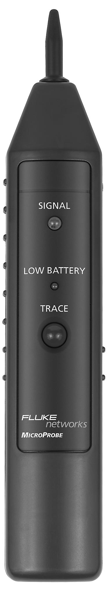
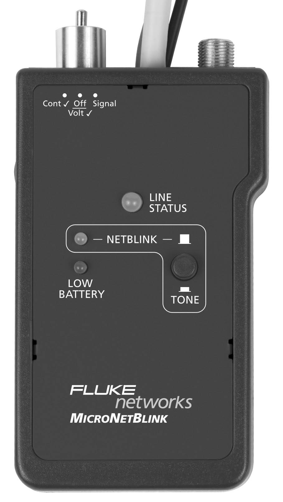
4 MICRONETBLINK & MICROPROBE Inductive Probe with Nonconductive tip Volume Control 3-Postion Switch: Continuity Test Off/ Volt Check Signal Signal LED Ring/Tip Polarity Test LED LED Netblink LED Low Battery LED F-Type Connector for tone tracing Netblink/ Tone Button Trace Button RJ11Connector for Continuity Test and Tip/Ring Signal. Red and Black Alligator clips for Continuity and Voltage Check. RJ45 Connector for flashing of Hublight and Tone Tracing. MicroNetBlink TM / MicroProbe TM
5 MICRONETBLINK Features 2-position NetBlink/Tone button for flashing a hub light or toning Toggle switch to control 3 modes of operation 2-color LED indicator for telephone line polarity, continuity and voltage testing 8-pin modular cable (RJ45) for flashing hub lights, tracing cables, and locating jacks Black and red alligator testing leads and standard 4-pin modular cable for individual wire tests or modular jack RJ11 tests Convenient compact size and simple application Low battery indicator MICROPROBE Features Special inductive plastic tip that prevents accidental shorts (possible with copper-tip tracers) Traces and identifies wires or cables in a bundle or group without damaging cable insulation Locates RJ45 jacks in wiring systems Adjustable volume level control and LED indicator for noisy work environments Power switch prevents battery drain Works with all tone generators including MICROSCANNER PRO, MICROMAPPER, MICRONETBLINK Low battery indicator ENGLISH - 3
6 Battery MICRONETBLINK requires a 9 Volt Alkaline battery. MICROPROBE requires a 9 Volt Alkaline battery. The low Battery LED will light up when a low battery condition is detected. Using the units with a low battery may effect the test accuracy. If the units are stored for more than one month, the battery should be removed. High Voltage Protection Do not touch the tip of MICROPROBE to the active circuit contact or line. Remember to adjust the volume rotary to reach an ideal volume level. Do not expose the units to extreme humidity or direct sunlight. Do not open the units or attempt to repair in case of malfunction. Please send it back to your distributor for repair or replacement. MICRONETBLINK is designed to withstand input voltage conditions that arise from normal telephony applications such as 48 VDC at less than 80 ma or 24 VAC used to power many keysets. Tests cannot be performed when hazard conditions exist on the inputs. MicroNetBlink TM / MicroProbe TM
7 MICRONETBLINK Tests Flashing the Hub Light Status 1. Set the toggle switch to the Signal position. 2. Plug the 8-position cable (RJ45) into the jack to be tested. 3. Verify that the button on the face of the MICRONETBLINK IS in the NETBLINK position. 4. In the wiring closet, view a light that blinks once every 4 seconds at the port to which the cable is connected. MICRONETBLINK will blink the hub's status indicator to assist locating a single channel in a busy wiring closet. Sending a Tone 1. Set the toggle switch to the Signal position. 2. Connect the black lead to ground and any other cable (coax, RJ45, or red alligator) to the cable to be traced. 3. Press the button to TONE position to activate the toner. 4. Reception of the tone will be loudest (Speaker) or brightest (LED) on the wire under test. Caution: Do not connect to an active AC circuit exceeding 24 V in this mode. ENGLISH - 5
8 Identifying Telephone Line Polarity 1. Set the toggle switch to the Off/Volt ü position. 2. Connect the black alligator test lead to the TIP (+) connection, usually green or blue. 3. Connect the red alligator test lead to the RING (-) connection, usually red or marked R. The LED indicator will light up: GREEN indicates normal polarity RED indicates reversed polarity RED/GREEN indicates presence of AC power on the telephone line Verifying Telephone Lines 1. Set the toggle switch to the Off/Volt ü position. 2. Insert the standard 4-pin modular cable into the modular wall jack, or connect the red alligator test lead to the RING (-) and the black alligator test lead to the TIP (+). The LED indicator will light up: GREEN indicates a correct wired telephone circuit that is on-hook GREEN (DIM) indicates a correct wired telephone circuit already in use or off-hook RED indicates a reversed polarity phone circuit 3. Use a second phone line to dial the number under test. RED and GREEN (rapidly flashing) indicates a ringing signal. MicroNetBlink TM / MicroProbe TM
9 4. Set the toggle switch to Cont ü to answer the line or go off-hook. Note: The brightness of the GREEN line status is an indicator of the amount of telephone loop current present while the toggle switch is in the Cont ü position. CAUTION: Telephone circuit voltages can be hazardous, never touch the metal of the test leads while the MicroNetBlink is attached to a telephone line. Testing for Low Voltage CAUTION: MicroNetBlink is designed for checking low voltage (less than 24 Volts DC or AC only). Do not connect to any high voltage circuits! 1. Set the toggle switch to the Off/Volt ü position. 2. Connect the red alligator test lead to a wire of the pair or circuit. 3. Connect the black alligator test lead to the other wire of the pair or circuit. If the LINE STATUS is GREEN, the black test lead is connected to a NEGATIVE(-) DC Voltage If the LINE STATUS is RED, the black test lead is connected to a POSITIVE (+) Voltage If the LINE STATUS is RED/GREEN, AC Voltage is present. ENGLISH - 7
10 Testing Continuity 1. Set the toggle switch to the Cont ü position. 2. Connect the red and black alligator test leads to the circuit to be tested. The LED indicator will light up: GREEN indicates a low resistance path from RED LEAD (+) to BLACK LEAD(-) GREEN (DIM) indicates that there is a high resistance path OFF indicates an open circuit. Testing Continuity using Tone 1. Set the toggle switch to the Signal position. 2. Connect the test leads to the pair to be tested. 3. Using a handset or headset at the remote end, touch the wire end(s) with the clip lead(s). Reception of tone is an indication of continuity. All above tests are applicable to modular plugs for line 1 only (red & green wires). Coax Testing To test un-terminated coaxial cables connect the red test lead to the outer shield and the black test lead to the center conductor, or connect the red test lead to the outer shield and the black test lead to the ground. MicroNetBlink TM / MicroProbe TM
11 To test terminated coaxial cables, connect the red test lead to the connector housing and the black test lead to center pin, or connect the red test lead to the connector housing and the black test lead to the ground. Appendix A MICRONETBLINK Dimensions: 4.53" x 2.49" x 1.03" 115mm x 63mm x 26mm Weight: 19g Power: 9V alkaline DC battery (not included) 1 ft. each of red and black alligator test lead for voltage and continuity testing 1 ft 4-pin modular RJ11 cord and plug for voltage and continuity testing 1 ft 8-pin modular RJ45 cord and plug for tone tracing, includes NetBlink feature to cause a 10 Base T or 10/100 Base T hub light to blink once every 4 seconds for easy identification in a busy wiring closet 1 'F' connector for tone tracing 3- position switch for operation mode control 2-color LED display for line polarity, continuity, and voltage tests Green LED indicates NetBlink active Red LED for low battery MICROPROBE Dimensions: 8.00" x 1.3" x 1.50" 203mm x 35mm x 38mm Weight: 16g Power: 9V alkaline DC battery (not included) ENGLISH - 9
12 Pen-style casing Special inductive plastic tip One push-button TRACE switch One battery low LED indicator One speaker and one LED for signal detection One rotary volume level switch MicroNetBlink TM / MicroProbe TM
13 LIMITED WARRANTY & LIMITATION OF LIABILITY Each Fluke Networks product is warranted to be free from defects in material and workmanship under normal use and service. The warranty period is one year and begins on the date of purchase. Parts, accessories, product repairs and services are warranted for 90 days. This warranty extends only to the original buyer or end-user customer of a Fluke Networks authorized reseller, and does not apply to disposable batteries, cable connector tabs, cable insulationdisplacement connectors, or to any product which, in Fluke Networks opinion, has been misused, altered, neglected, contaminated, or damaged by accident or abnormal conditions of operation or handling. Fluke Networks warrants that software will operate substantially in accordance with its functional specifications for 90 days and that it has been properly recorded on non-defective media. Fluke Networks does not warrant that software will be error free or operate without interruption. Fluke Networks authorized resellers shall extend this warranty on new and unused products to end-user customers only but have no authority to extend a greater or different warranty on behalf of Fluke Networks. Warranty support is available only if product is purchased through a Fluke Networks authorized sales outlet or Buyer has paid the applicable international price. Fluke Networks reserves the right to invoice Buyer for importation costs of repair/ replacement parts when product purchased in one country is submitted for repair in another country. Fluke Networks warranty obligation is limited, at Fluke Networks option, to refund of the purchase price, free of charge repair, or replacement of a defective product which is returned to a Fluke Networks authorized service center within the warranty period. To obtain warranty service, contact your nearest Fluke Networks authorized service center to obtain return authorization information, then send the product to that service center, with a description of the difficulty, postage and insurance prepaid (FOB Destination). Fluke Networks assumes no risk for damage in transit. Following warranty repair, the product will be returned to Buyer, transportation prepaid (FOB Destination). If Fluke Networks determines that failure was caused by neglect, misuse, contamination, alteration, accident or abnormal condition of operation or handling, or normal wear and tear of mechanical components, Fluke Networks will provide an estimate of repair costs and obtain authorization before commencing the work. Following repair, the product will be returned to the Buyer transportation prepaid and the Buyer will be billed for the repair and return transportation charges (FOB Shipping Point). THIS WARRANTY IS BUYER S SOLE AND EXCLUSIVE REMEDY AND IS IN LIEU OF ALL OTHER WARRANTIES, EXPRESS OR IMPLIED, INCLUDING BUT NOT LIMITED TO ANY IMPLIED WARRANTY OF MERCHANTABILITY OR FITNESS FOR A PARTICULAR PURPOSE. FLUKE NETWORKS SHALL NOT BE LIABLE FOR ANY SPECIAL, INDIRECT, INCIDENTAL OR CONSEQUENTIAL DAMAGES OR LOSSES,
14 INCLUDING LOSS OF DATA, ARISING FROM ANY CAUSE OR THEORY. Since some countries or states do not allow limitation of the term of an implied warranty, or exclusion or limitation of incidental or consequential damages, the limitations and exclusions of this warranty may not apply to every buyer. If any provision of this Warranty is held invalid or unenforceable by a court or other decision-maker of competent jurisdiction, such holding will not affect the validity or enforceability of any other provision. Fluke Networks, Inc. PO Box 777 Everett, WA USA 6-01 Registration Registering your product with Fluke Networks gives you access to valuable information on product updates, troubleshooting tips, and other support services. To register, fill out and return the postagepaid card provided, or fill out the online registration form on the Fluke Networks website.
15 MICROTOOLS
36 AC/DC True RMS. Clamp Meter. P Read First: Safety Information
 36 / True RMS Clamp Meter Instruction Sheet P Read First: Safety Information To ensure safe operation and service of the meter, follow these instructions: Avoid working alone so assistance can be rendered.
742A Series Resistance Standards
 742A Series Resistance Standards Instruction Manual PN 850255 September 1988 Rev. 1, 4/89 1988-2015 Fluke Corporation. All rights reserved. All product names are trademarks of their respective companies.
12B/18 MultiMeter Instruction Sheet
 12B/18 MultiMeter Instruction Sheet P Read First: Safety Information To ensure that the meter is used safely, follow these instructions: Do not use the meter if the meter or test leads appear damaged,
5520A. Service Manual. PQ Option
 5520A PQ Option Service Manual PN 1629170 October 2001 2001 Fluke Corporation, All rights reserved. Printed in USA All product names are trademarks of their respective companies. LIMITED WARRANTY AND LIMITATION
CABLE TRACER & PHONE TESTER / GENERATOR
 CABLE TRACER & PHONE TESTER / GENERATOR 183 CB-A Amplifier Probe INSTRUCTION MANUAL Amplifier Probe Amplifier Probe 183 CB-A Figure 1 Amplifier Probe 183 CB-A Figure 2 Features The Amplifier Probe is designed
1507/1503. Insulation Testers. Users Manual
 1507/1503 Insulation Testers Users Manual June 2005 2005 Fluke Corporation. All rights reserved. All product names are trademarks of their respective companies. LIMITED WARRANTY AND LIMITATION OF LIABILITY
1523, 1524 Thermometer Readout User s Guide
 1523, 1524 Thermometer Readout User s Guide ThermoWorks Inc. 1762 W. 20 S. #100 Lindon, UT 84042 Phone: 801.756.7705 Fax: 801.756.8948 Email: info@thermoworks.com Web: www.thermoworks.com Rev. 891001_EN
374/375/376. Calibration Manual. Clamp Meter
 374/375/376 Clamp Meter Calibration Manual December 2010 2010 Fluke Corporation. All rights reserved. Specifications are subject to change without notice. All product names are trademarks of their respective
MS6813. Users Manual TEST BNC MS6813 TRANSMITTER SHIELD OFF CONT TONE. Multi-Function Wire Tracer. Short Reversed Miswire Split Pairs
 Multi-Function Wire Tracer Users Manual MS6813 RJ45 CO-AX RJJJ Multi-Function Wire Tracer 1-2 3-6 4-5 7-8 SHIELD Short Reversed Miswire Split Pairs TEST CONT OFF TONE red fauit green good BNC 10 Base T
AT Advanced Wire Tracer. Users Manual
 AT-1000 Advanced Wire Tracer Users Manual AT-1000 Advanced Wire Tracer English Users Manual AT1000_Rev001 2008 Amprobe Test Tools. All rights reserved. Limited Warranty and Limitation of Liability Your
5520A. Operators Manual. PQ Option
 5520A PQ Option Operators Manual PN 1608366 May 2001 2001 Fluke Corporation. All rights reserved. Printed in USA All product names are trademarks of their respective companies. LIMITED WARRANTY AND LIMITATION
WireMaster Coax BNC PN: Rev C 2/13
 WireMaster Coax BNC Instruction Manual PN: 3274 84-868 Rev C 2/13 Table of Contents Features...... 2 Introduction... 3 Warnings and Cautions... 3 Specifications...4 Typical Cable/Wire Resistances...5 Control
Circuit Breaker Finder
 ECB50-FGIS Circuit Breaker Finder and AC Line Tracer User Manual ECB50-FGIS Circuit Breaker Finder and AC Cable Tracer Contents Safety Information...3 Symbols Used in this Manual...3 Introduction...4 Finding
Insulation Tester. Users Manual
 1508 Insulation Tester Users Manual June 2005 Rev. 1, 2/09 2005-2009 Fluke Corporation. All rights reserved. Printed in China. Specifications are subject to change without notice. All product names are
Models 110, 111 & 112
 Models 110, 111 & 112 True RMS Multimeters Users Manual November 2000 (English), Rev 1 7/01 2000-2001 Fluke Corporation. All rights reserved. Printed in USA Limited Warranty and Limitation of Liability
SureGrip TM. XWWarning
 80PK-22 SureGrip TM Immersion Temperature Probe Instruction Sheet XWWarning To avoid electrical shock, do not use this probe when voltages exceeding 24 V ac rms or 60 V dc are present. The probe tip is
For detailed specifications and ordering info go to
 For detailed specifications and ordering info go to www.testequipmentdepot.com ECB50A, ECB50A-E, ECB50A-FGIS Circuit Breaker Finder and AC Cable Tracer User Manual For detailed specifications and ordering
AT Underground Cable/Pipe Locator System. Users Manual Mode d emploi Bedienungshandbuch Manuale d Uso Manual de uso Användarhandbok
 AT-3500 Underground Cable/Pipe Locator System Users Manual Mode d emploi Bedienungshandbuch Manuale d Uso Manual de uso Användarhandbok For detailed specifications and ordering info go to www.testequipmentdepot.com
HART Mode. Users Guide. July Fluke Corporation. All rights reserved. All product names are trademarks of their respective companies.
 754 HART Mode Users Guide July 2011 2011 Fluke Corporation. All rights reserved. All product names are trademarks of their respective companies. LIMITED WARRANTY AND LIMITATION OF LIABILITY This Fluke
VideoEase VGA 1x4 Distribution Hub (500150, ) Installation Guide
 Installation Guide") VideoEase VGA 1x4 Distribution Hub (500150, 500151) Installation Guide P/N: 94-000624-A SE-000605-A Table of Contents 1. Overview...3 1.1. Description...3 1.2. Features...4 2. Technical Specifications...5
VideoEase VGA 1x4 Distribution Hub (500150, 500151) Installation Guide P/N: 94-000624-A SE-000605-A Table of Contents 1. Overview...3 1.1. Description...3 1.2. Features...4 2. Technical Specifications...5
Glass Electrode Meter
 Glass Electrode Meter INSTRUCTION MANUAL FOR Glass Electrode R/C Meter MODEL 2700 Serial # Date PO Box 850 Carlsborg, WA 98324 U.S.A. 360-683-8300 800-426-1306 FAX: 360-683-3525 http://www.a-msystems.com
99 Washington Street Melrose, MA Fax TestEquipmentDepot.com # # AAC Clamp Meter. Instruction Manual
 99 Washington Street Melrose, MA 02176 Fax 781-665-0780 TestEquipmentDepot.com #61-732 #61-736 400 AAC Clamp Meter Instruction Manual AC HOLD APO DC KMΩ mva WARNING Read First: Safety Information Understand
16 Multimeter with Temperature
 16 Multimeter with Temperature Instruction Sheet P Read First: Safety Information To ensure that the meter is used safely, follow these instructions: Do not use the meter if the meter or test leads appear
INSTRUCTION MANUAL MARTINDALE EZ150 / EZ650 SOCKET TESTER 1. INTRODUCTION. ELECTRIC Trusted by professionals
 EZ150 / EZ650 SOCKET TESTER INSTRUCTION MANUAL GENERAL SAFETY INFORMATION: Always read before proceeding. These instructions contain both information and warnings that are necessary for the safe operation
FOX JR. & HOUND JR. Instruction Manual
 FOX JR. & HOUND JR. Instruction Manual Table of Contents 1. Introduction...................... 1 2. FOX Jr Features................... 2 3. HOUND Jr Features................ 2 4. Fox Jr Diagram...................
Pro. SimpliFiber. Getting Started Guide. Optical Power Meter and Fiber Test Kits
 SimpliFiber Pro Optical Power Meter and Fiber Test Kits Getting Started Guide PN 3314816 September 2008, Rev. 2 6/12 2008, 2010, 2012 Fluke Corporation. Printed in USA. All product names are trademarks
80i-600A AC Current Probe
 x Instruction Sheet 80i-600A AC Current Probe INTRODUCTION The Model 80i-600A is a clamp-on ac current probe designed to extend the current measuring capability of an ac current meter to 600 amperes. A
312, 316, 318. Clamp Meter. Users Manual
 312, 316, 318 Clamp Meter Users Manual PN 1989445 July 2002 Rev.2, 2/06 2002, 2006 Fluke Corporation. All rights reserved. Printed in China. All product names are trademarks of their respective companies.
ER200 COMPACT EMERGENCY CRANK DIGITAL WEATHER ALERT RADIO OWNER S MANUAL
 ER200 COMPACT EMERGENCY CRANK DIGITAL WEATHER ALERT RADIO OWNER S MANUAL Table of Contents -------------------------------------- 2 Features ----------------------------------------------- 3 Controls and
Vi6208, Vi6216, Vi6232 Vi6308, Vi6316, Vi6332
 MODELs Vi6208, Vi6216, Vi6232 Vi6308, Vi6316, Vi6332 Automatic Video Compensation UTP Receiver Hubs User s Manual 7810 Trade Street, Suite 100 San Diego, CA 92121, U.S.A. Phone: (858) 484-5209 Fax: (858)
Radio Remote(s) (Installation Manual)
 (Installation Manual)") Radio Remote(s) (Installation Manual) 87 Progress Avenue, Tyngsboro, MA 01879, USA Phone (978) 649-4ECU Fax (978) 649-8363 http://www.qtiusa.com Trademarks, Version, Printing, and Copyright Trademarks
Radio Remote(s) (Installation Manual) 87 Progress Avenue, Tyngsboro, MA 01879, USA Phone (978) 649-4ECU Fax (978) 649-8363 http://www.qtiusa.com Trademarks, Version, Printing, and Copyright Trademarks
Broadband Step-Up Transformer. User Manual
 Broadband Step-Up Transformer User Manual 990-1930 09/2004 Introduction Introduction About this unit The APC Step-Up Transformer provides 220 V power from 60 VAC Broadband cable systems. Safety Electrical
Using the USB Output Port to Charge a Device
 Table of Contents ----------------------------------- 2 Features ----------------------------------------------- 3 Controls and Functions ---------------------------------- 4 ER210 Power Sources -----------------------------------
INSTRUCTION MANUAL FOR CELL SIMULATOR MODEL 2410
 Cell Simulator INSTRUCTION MANUAL FOR CELL SIMULATOR MODEL 2410 A-M Systems PO Box 850 Carlsborg, WA 98324 U.S.A. 360-683-8300 800-426-1306 FAX: 360-683-3525 http://www.a-msystems.com Disclaimer THIS EQUIPMENT
Shiba Drive USER MANUAL
 Shiba Drive USER MANUAL Thank you for purchasing the Suhr Shiba Drive pedal. Please take the time to read this manual to get the most out of your pedal. The more you familiarize yourself with the features
T+ and T+ PRO Electrical Tester
 T+ and T+ PRO Electrical Tester Instruction Sheet Introduction The Fluke T+ and T+ PRO Electrical Testers (the Tester ) have the following features: AC and dc voltage measurement, 12 V to 600 V, with or
T6-1000/T Service Information. Electrical Tester
 T6-1000/T6-600 Electrical Tester Service Information February 2018 2018 Fluke Corporation. All rights reserved. All product names are trademarks of their respective companies. Specifications are subject
DA6002D-DA10004D. INSTALLATION / OWNER'S MANUAL Mobile Power Amplifiers
 DA6002D-DA10004D INSTALLATION / OWNER'S MANUAL Mobile Power Amplifiers Preparation Please read entire manual before installation. Due to the technical nature of amplifiers, it is highly recommended that
POWER TRACE TM TASCO, INC.
 POWER TRACE TM Instruction Manual PTL610 TASCO, INC. HOW YOUR POWER TRACE TM OPERATES The Power Trace TM is composed of two primary components: the Receiver and the Transmitter. When the Transmitter is
DL102 Counter Loop Amplifier
 DL102 Counter Loop Amplifier USER MANUAL MAN 234A Contents Overview...3 System Includes...3 Maintenance and Recycling Instructions...3 Safety Information...4 Quick Setup...5 Setup...6 Loop Amplifier...6
Dawson DDM190. Digital Multimeter User s Manual
 Dawson DDM190 Digital Multimeter User s Manual TABLE OF CONTENTS LIMITED WARRANTY AND LIMITATION OF LIABILITY... 3 Out of the Box... 3 Accessories.. Error! Bookmark not defined. Safety Information... 7
RIOT DISTORTION USER GUIDE
 RIOT DISTORTION USER GUIDE Thank you for purchasing the Suhr Riot Distortion Pedal. Please take the time to read this manual to get the most out of the Riot. The more you familiarize yourself with the
Cable I.D. Live. Primary or Secondary In or Out of the Trench TX-Former to TX-Former TX-Former to Meter Energized or Grounded.
 Cable I.D. Live Primary or Secondary In or Out of the Trench TX-Former to TX-Former TX-Former to Meter Energized or Grounded www.aquatronics.com i ii TABLE OF CONTENTS Warning Description Battery Test
LV-1K Line Verification Panel with Key Switch
 Designed, Manufactured and Supported in the USA VIKING PRODUCT MANUAL COMMUNICATION & SECURITY SOLUTIONS LV-1K Line Verification Panel with Key Switch October 30, 2013 Line Verification Panel with Key
DA560D COMPACT SERIES. INSTALLATION / OWNER'S MANUAL Mobile Power Amplifiers
 DA560D COMPACT SERIES INSTALLATION / OWNER'S MANUAL Mobile Power Amplifiers Preparation Please read entire manual before installation. Due to the technical nature of amplifiers, it is highly recommended
Safety. This symbol, adjacent to a terminal, indicates that, under normal use, hazardous voltages may be present.
 9305 Safety International Safety Symbols This symbol, adjacent to another symbol or terminal, indicates the user must refer to the manual for further information. This symbol, adjacent to a terminal, indicates
SX204. Headphone Amplifier. Symetrix. Owner s Manual
 Symetrix SX204 Headphone Amplifier Owner s Manual Symetrix Inc. 14926 35th Avenue West Lynnwood, Washington 98037 Voice: (206) 787-3222, (800) 288-8855 Fax: (206) 787-3211 Copyright 1988, 1994 Symetrix
V-136RTHF 36 ZONE TALKBACK INTERCOM/ PAGE CONTROL UNIT
 VSP-V-13RTHF Issue V-13RTHF 3 ZONE TALKBACK INTERCOM/ PAGE CONTROL UNIT GENERAL The V-13RTHF is a single-path dial select microcomputer controlled intercom and page control unit used with a 1A2 key system
XPR522 XPR540. XPR SERIES INSTALLATION / OWNER'S MANUAL Mobile Power Amplifiers
 XPR522 XPR540 XPR SERIES INSTALLATION / OWNER'S MANUAL Mobile Power Amplifiers Preparation Please read entire manual before installation. Due to the technical nature of amplifiers, it is highly recommended
16 Multimeter with Temperature
 16 Multimeter with Temperature P Read First: Safety Information Instruction Sheet To ensure that the meter is used safely, follow these instructions: Do not use the meter if the meter or test leads appear
1000A AC DIGITAL CLAMPMETER MODEL KM 3060
 An ISO 9001:2008 Company 1000A AC DIGITAL CLAMPMETER MODEL KM 3060 GENERAL SPECIFICATIONS : í AC Current : 0.01A ~ 1000A í AC Voltage : 1V ~ 750V í DC Voltage : 1V ~ 1000V í Resistance : 0.1W ~ 2MW í Frequency
Wilcom MODEL T336B CIRCUIT TEST SET. Operating Instructions
 Wilcom MODEL T336B CIRCUIT TEST SET Operating Instructions T336B Circuit Test Set Operating Instructions 810-311-007 June 2005 Copyright (c) 2005 Wilcom All Rights reserved Wilcom reserves the right to
INSTRUCTION MANUAL. Model Autoranging DMM ProbeMeter TM. Measures voltage, resistance, frequency, capacitance, temperature, and duty cycle.
 INSTRUCTION MANUAL Model 403380 Autoranging DMM ProbeMeter TM Measures voltage, resistance, frequency, capacitance, temperature, and duty cycle. Back lit LCD with Autorange and full function displays Audible
Far End Device II Model 1342
 3 Far End Device II Model 1342 Operating Instructions Optimized for ADSL2+ May 2007 78-8130-0876-6-C Table of Contents Introduction...3 Power-up...4 Connecting the 3M Far End Device II...5 Installing,
Active CCTV Receiver Balun Installation Guide
 Active CCTV Receiver Balun 500015 Installation Guide P/N: 94-000304-C SE-000266-C Copyright Notice: Copyright 2009 MuxLab Inc. All rights reserved. Printed in Canada. No part of this publication may be
STAFF User Manual. Manual Part #
 STAFF User Manual Manual Part # 030-00085-00 Introduction Congratulations on the purchase of your new STAFF Secondary Fault Locator. The STAFF is specially designed to detect conductor to earth/ground
AM-510 Commercial / Residential Multimeter. AM-510-EUR Digital Multimeter. Users Manual
 AM-510 Commercial / Residential Multimeter AM-510-EUR Digital Multimeter Users Manual AM-510 Commercial / Residential Multimeter AM-510-EUR Digital Multimeter English Users Manual Limited Warranty and
XPA2100 XPA4100 XPA6100. XPA SERIES INSTALLATION/OWNER S MANUAL Mobile Power Amplifiers
 XPA2100 XPA4100 XPA6100 XPA SERIES INSTALLATION/OWNER S MANUAL Mobile Power Amplifiers XPA SERIES INSTALLATION Preparation Please read entire manual before installation. Due to the technical nature of
DA604D DA954D DA501D DA801D COMPACT SERIES. INSTALLATION / OWNER'S MANUAL Mobile Power Amplifiers
 DA604D DA954D DA501D DA801D COMPACT SERIES INSTALLATION / OWNER'S MANUAL Mobile Power Amplifiers Preparation Please read entire manual before installation. Due to the technical nature of amplifiers, it
XIA3145 INSTALLATION/OWNER S MANUAL 2/1-Channel Mobile Power Amplifier
 XIA3145 INSTALLATION/OWNER S MANUAL 2/1-Channel Mobile Power Amplifier XIA3145 INSTALLATION Preparation Please read entire manual before installation. Due to the technical nature of amplifiers, it is highly
Electrical Multimeter
 113 Electrical Multimeter Instruction Sheet Safety Information A Warning statement identifies hazardous conditions and actions that could cause bodily harm or death. A Caution statement identifies conditions
51-54 Series II. Thermometer
 51-54 Series II Thermometer Product Overview Présentation du produit Descrizione generale del prodotto Produktübersicht Características de los productos Informações gerais sobre o produto Productoverzicht
374/375/376 Clamp Meter
 374/375/376 Clamp Meter Users Manual PN 3608883 July 2010 2010 Fluke Corporation. All rights reserved. Printed in China. Specifications are subject to change without notice. All product names are trademarks
Warranty Terms & Conditions
 Warranty Terms & Conditions Is my guitar under warranty? How long, what specific parts? Ibanez Electric Guitars and Basses Limited Warranty Ibanez Electric Guitars and Basses sold in the United States
323/324/325 Clamp Meter
 323/324/325 Clamp Meter Users Manual May 2012 Rev.1, 06/15 2012-2015 Fluke Corporation. All rights reserved. Specifications are subject to change without notice. All product names are trademarks of their
AM-500 Autoranging Mulitmeter. AM-500-EUR Digital Multimeter. Users Manual
 AM-500 Autoranging Mulitmeter AM-500-EUR Digital Multimeter Users Manual AM-500 Autoranging Mulitmeter AM-500-EUR Digital Multimeter English Users Manual 8/2012, 4275548 A 2012 Amprobe Test Tools. All
The table below lists the symbols used on the Clamp and/or in this manual. Important Information. See manual.
 i310s AC/DC Current Clamp Instruction Sheet Introduction The i310s Current Clamp ( Clamp ) has been designed for use with oscilloscopes and digital multimeters for accurate nonintrusive measurement of
TLS-3A. Telephone Line Simulator. User Manual , Rev. B Covers Model TLS-3A-01
 User Manual TLS-3A Telephone Line Simulator 40-400-00010, Rev. B Covers Model TLS-3A-01 Teltone Corporation 22121-20th Avenue SE Bothell, Washington 98021-4408 USA Phone: 1-800-426-3926 or 425-487-1515
FRYCORDER Power Cord Burn-in Generator
 FRYCORDER Power Cord Burn-in Generator Made in USA FRYCORDER Power Cord Burn-in Generator Copyrights & Trademarks Copyright Hagerman Audio Labs 0. All rights reserved. No part of this document may be photocopied,
User s Guide. Model MA A AC Mini Clamp-on Meter
 User s Guide Model MA150 200A AC Mini Clamp-on Meter Introduction Congratulations on your purchase of Extech s MA150 AC Mini Clamp Meter. This meter is shipped fully tested and calibrated and, with proper
600A Clamp Meters w/tightsight Display
 V 750V #61-764 #61-766 #61-768 600A Clamp Meters w/tightsight Display Instruction Manual 99 Washington Street Melrose, MA 02176 Fax 781-665-0780 TestEquipmentDepot.com CAT.IV 600V CAT.III 1000V 600A 61-766
374/375/376 Clamp Meter
 374/375/376 Clamp Meter Users Manual PN 3608883 July 2010 2010 Fluke Corporation. All rights reserved. Printed in China. Specifications are subject to change without notice. All product names are trademarks
INSTRUCTION MANUAL LM192 LIGHT METER ALWAYS READ THESE INSTRUCTIONS BEFORE PROCEEDING CONTENTS. Precautions 1. SAFETY INFORMATION
 ALWAYS READ THESE INSTRUCTIONS BEFORE PROCEEDING LM9 LIGHT METER Thank you for buying one of our products. For safety and a full understanding of its benefits please read this manual before use. Technical
INSTRUCTION MANUAL. MODEL: Vintage 60R. Vintage Series Guitar Amplifi er
 INSTRUCTION MANUAL MODEL: Vintage 60R Vintage Series Guitar Amplifi er 2 INTRODUCTION Thank you for choosing this Johnson amplifier. Please read this manual carefully and completely before operating your
ER200 COMPACT EMERGENCY CRANK DIGITAL WEATHER ALERT RADIO OWNER S MANUAL
 ER200 COMPACT EMERGENCY CRANK DIGITAL WEATHER ALERT RADIO OWNER S MANUAL Table of Contents -------------------------------------- 2 Features ----------------------------------------------- 3 Controls and
Current Probe Fixture Instruction Manual
 Current Probe Fixture Instruction Manual 1 TABLE OF CONTENTS INTRODUCTION 3 GENERAL INFORMATION 4 TEST METHODS 5 SAFETY 7 FIGURES 8 FORMULAS 10 MAINTENANCE 11 WARRANTY 12 2 INTRODUCTION figure 1 Mechanical
Overview. Thank you for purchasing the Suhr Eclipse Dual Overdrive/Distortion Pedal.
 User Guide Table of Contents Overview 3 Getting Connected 4 Channel Selection / Bypass 5 Controls 6 Battery Monitor 7 FX Link (External Control) 8 Sample Settings 9 Technical Specifications 10 Warranty
Instruction Manual ET4 ELECTRICAL TESTER
 ET4 ELECTRICAL TESTER Instruction Manual GENERAL SAFETY INFORMATION: Always read before proceeding. Warning These instructions contain both information and warnings that are necessary for the safe operation
TS 100. Cable Fault Finder. Users Guide
 99 Washington Street Melrose, MA 02176 Phone 781-665-1400 Toll Free 1-800-517-8431 Visit us at www.testequipmentdepot.com TS 100 Cable Fault Finder Users Guide PN 2458065 October 2005 2005 Fluke Corporation.
INSTALLATION GUIDE. Video Balun Transceiver with fixed BNC for twisted pair operation with other balun transceivers or active receivers.
 INSTALLATION GUIDE VB37M Video Balun Transceiver for Twisted Pair Description Video Balun Transceiver with fixed BNC for twisted pair operation with other balun transceivers or active receivers. The VB37M
PCO-7114 Laser Diode Driver Module Operation Manual
 PCO-7114 Laser Diode Driver Module Operation Manual Directed Energy, Inc. 1609 Oakridge Dr., Suite 100, Fort Collins, CO 80525, (970) 493-1901 sales@ixyscolorado.com www.ixyscolorado.com Manual Document
INSTALLATION GUIDE ET1551U. IP Video Camera Over Single Twisted Wire Ethernet Extender with EtherStretch. Description
 INSTALLATION GUIDE ET1551U IP Video Camera Over Single Twisted Wire Ethernet Extender with EtherStretch Description The ET1551U is another component of the NITEK EtherStretch line. This Environmentally
3M Dynatel Far End Device III
 3M Dynatel Far End Device III User s Guide PAIR 1 GND CO PAIR 2 F1 F2 STATUS Dynatel Far End Device III 1 1/2 0 Future-Proof Testing Platform February 2009 78-8140-2657-7-A 3 2 3M Dynatel Far End Device
374 FC/375 FC/376 FC Clamp Meter
 374 FC/375 FC/376 FC Clamp Meter PN 4705494 September 2015 2015 Fluke Corporation. All rights reserved. Specifications are subject to change without notice. All product names are trademarks of their respective
USER MANUAL. MODEL 457B Seven Port Active Twinax Star Hub. SALES OFFICE (301) TECHNICAL SUPPORT (301)
 TECHNICAL SUPPORT (301)") USER MANUAL MODEL 457B Seven Port Active Twinax Star Hub An ISO-9001 Certified Company Part #07M457B-C Doc. #069011UC Revised 4/22/98 SALES OFFICE (301) 975-1000 TECHNICAL SUPPORT (301) 975-1007 http://www.patton.com
USER MANUAL MODEL 457B Seven Port Active Twinax Star Hub An ISO-9001 Certified Company Part #07M457B-C Doc. #069011UC Revised 4/22/98 SALES OFFICE (301) 975-1000 TECHNICAL SUPPORT (301) 975-1007 http://www.patton.com
Inline Antenna Signal Amplifier
 1500528 User s Guide Inline Antenna Signal Amplifier We hope you enjoy your In-Line Antenna Signal Amplifier from RadioShack. Please read this user s guide before using your new signal amplif ier. Package
RIGOL. User s Guide. RP5600 Passive Probe. July 2010 RIGOL Technologies, Inc.
 User s Guide RP5600 Passive Probe July 2010 RIGOL Technologies, Inc. Guaranty and Declaration Copyright 2010 RIGOL Technologies, Inc. All Rights Reserved. Trademark Information RIGOL is a registered trademark
SureCall TM CM800 65dB
 SureCall TM CM800 65dB Cellular Band Building Repeater User Manual Model: CM800 FCC ID: RSNCM2000 CONTENTS OF THE PACKAGE fdgbsddg 1. CM800 Amplifier with connectors: N female type 2. Mounting Kit 3. 110V
AT-4000 Series. Advanced Wire Tracer. Users Manual
 AT-4000 Series Advanced Wire Tracer Users Manual AT-4000 Series Advanced Wire Tracer English Users Manual AT4000CON_Rev001 2008 Amprobe Test Tools. All rights reserved. 1 Limited Warranty and Limitation
712B/714B. Calibration Manual. RTD/Thermocouple Calibrator
 712B/714B RTD/Thermocouple Calibrator Calibration Manual March 2015 2015 Fluke Corporation. All rights reserved. Specifications are subject to change without notice. All product names are trademarks of
User s Guide Instructions for Installation and Operation
 User s Guide Instructions for Installation and Operation 2.4 GHZ SPREAD SPECTRUM REMOTE CONTROLS Keyfob Transmitters Models KTX24SS1 KTXW24SS3 KTX24SS2 KTX24SS3 Wall Mount Models NTX24SS1 NTX24SS2 Remote
Gypsy Statement of Limited Warranty. Part 1 General Terms
 Gypsy Statement of Limited Warranty Part 1 General Terms This Statement of Limited Warranty includes Part 1 General Terms, and Part2 Warranty Information. The warranties provided by PROVO CRAFT AND NOVELTY,
For Precise Volume Adjustment with Programmable Muting in Any Room
 INSTALLATION & USER GUIDE For Precise Volume Adjustment with Programmable Muting in Any Room 12 STEP MUTING WALL MOUNT VOLUME CONTROL V-12M V-12M 12 STEP MUTING WALL MOUNT VOLUME CONTROL TABLE OF CONTENTS
USER MANUAL. MODEL 2017A RS-232 to 20ma Current Loop Converter. SALES OFFICE (301) TECHNICAL SUPPORT (301)
 TECHNICAL SUPPORT (301)") USER MANUAL MODEL 2017A RS-232 to 20ma Current Loop Converter Part# 07M2017A-A Doc# 073021UA Revised 10/15/93 SALES OFFICE (301) 975-1000 TECHNICAL SUPPORT (301) 975-1007 http://www.patton.com 1.0 WARRANTY
USER MANUAL MODEL 2017A RS-232 to 20ma Current Loop Converter Part# 07M2017A-A Doc# 073021UA Revised 10/15/93 SALES OFFICE (301) 975-1000 TECHNICAL SUPPORT (301) 975-1007 http://www.patton.com 1.0 WARRANTY
LongReach II Active CCTV Receiver Hub [8P], [16P] Installation Guide
![LongReach II Active CCTV Receiver Hub [8P], [16P] Installation Guide](/thumbs/93/111051660.jpg "LongReach II Active CCTV Receiver Hub [8P], [16P] Installation Guide") LongReach II Active CCTV Receiver Hub 500126 [8P], 500127 [16P] Installation Guide P/N: 94-000709-A SE-000709-A Copyright Notice: Copyright 2012 MuxLab Inc. All rights reserved. Printed in Canada. No part
LongReach II Active CCTV Receiver Hub 500126 [8P], 500127 [16P] Installation Guide P/N: 94-000709-A SE-000709-A Copyright Notice: Copyright 2012 MuxLab Inc. All rights reserved. Printed in Canada. No part
CURRENT SENSING 12VOLT TRIGGER CS12V
 I N S T A L L A T I O N G U I D E CURRENT SENSING 12VOLT TRIGGER CS12V CONGRATULATIONS! Thank you for choosing the CS12V from Niles. With proper installation and operation, you should enjoy years of trouble-free
Wilcom MODEL T136BSBZW CIRCUIT TEST SET. Operating Instructions
 Wilcom MODEL T136BSBZW CIRCUIT TEST SET Operating Instructions T136BSB Current Test Set Operating Instructions 811-230-007 February 2007 Copyright (c) 2007 Wilcom All Rights reserved Wilcom reserves the
User Instructions. Model PS-2001L. Power Supply. Model SPS Power Supply. Audiocom Intercom Systems Rev. A, 4/2001.
 User Instructions PS-00L Model PS-00L Power Supply SPS-00 Volume Model SPS-00 Power Supply Audiocom Intercom Systems 950-7699-000 Rev. A, /00 FCC Statement This equipment uses, and can radiate radio frequency
80i-110s. AC/DC Current Probe Instructions. Introduction
 80i-110s.book Page 1 Monday, December 5, 2016 12:12 PM 80i-110s AC/DC Current Probe Instructions Introduction The Fluke 80i-110s (the Probe or Product) is a clamp-on AC/DC Current Probe that reproduces
automatic embosser & die cutter USER MANUAL
 TM TM automatic embosser & die cutter USER MANUAL CREATE A BEAUTIFUL LIFE IN THE BOX Cut n Boss machine (7) Embossing Folders (12) Cutting Dies Platforms (2) (1) Platform B (1) Platform D Magnetic Shim