Fabrication of long-period fiber gratings by CO₂ laser irradiation for high temperature applications
|
|
|
- Leonard Miles
- 5 years ago
- Views:
Transcription

. Masters Theses. 6833. http://scholarsmine.mst.")
1 Scholars' Mine Masters Theses Student Theses and Dissertations Spring 2008 Fabrication of long-period fiber gratings by CO₂ laser irradiation for high temperature applications Tao Wei Follow this and additional works at: Part of the Electrical and Computer Engineering Commons Department: Electrical and Computer Engineering Recommended Citation Wei, Tao, "Fabrication of long-period fiber gratings by CO₂ laser irradiation for high temperature applications" (2008). Masters Theses This Thesis - Open Access is brought to you for free and open access by Scholars' Mine. It has been accepted for inclusion in Masters Theses by an authorized administrator of Scholars' Mine. This work is protected by U. S. Copyright Law. Unauthorized use including reproduction for redistribution requires the permission of the copyright holder. For more information, please contact scholarsmine@mst.edu.
2
3 FABRICATION OF LONG-PERIOD FIBER GRATINGS BY CO 2 LASER IRRADIATION FOR HIGH TEMPERATURE APPLICATIONS by TAO WEI A THESIS Presented to the Faculty of the Graduate School of the MISSOURI UNIVERSITY OF SCIENCE AND TECHNOLOGY In Partial Fulfillment of the Requirements for the Degree MASTER OF SCIENCE IN ELECTRICAL ENGINEERING 2008 Approved by Dr. Hai Xiao, Advisor Dr. Steve Watkins Dr. Hai-Lung Tsai
4 2008 Tao Wei All Rights Reserved
5 iii ABSTRACT Long period fiber gratings (LPFG) have unique advantages such as small insertion loss, low retro-reflection, good sensory property and low cost fabrication. LPFGs have found many applications in optical fiber communications as well as in optical fiber sensors. Recently, high-performance LPFGs have been successfully fabricated by CO 2 laser irradiations. The unique thermal stability enables many potential sensing applications in high temperature environments. In this thesis, the CO 2 laser based LPFG fabrication system with in-situ monitoring has been demonstrated. High quality LPFGs were successfully fabricated using the system. The transmission spectra of the LPFGs possessed a strong attenuation (>25dB), a negligible device loss (<1dB) and a narrow FWHM (~7 nm). The resonance wavelength showed a linear dependence on grating periods as predicted by the Bragg condition. An interferometric method was developed to measure the refractive index change caused by CO 2 laser irradiation, which helped tune the laser parameters to optimize the fabrication process. High temperature performance and survivability of the fabricated LPFGs were evaluated systematically. It has been found that the thermal shock process could dramatically improve the thermal stability of the LPFG device. Two chemical sensing applications of LPFG were demonstrated. In the first one, the ambient refractive index sensing ability of bare LPFG was examined. The experimental data showed a good agreement with the simulation results. In the second one, the Palladium coated LPFG was used to monitor the concentration of hydrogen gas at different temperatures ranging from 25 C to 200 C. The sensitivity, response time and repeatability have been tested.
6 iv ACKNOWLEDGMENTS I would like to take this opportunity to thank all those people who helped me with the successful completion of my research. First, I would like to express my gratitude to my advisor Dr. Hai Xiao, without who this research could be considered incomplete. I thank him for giving me a chance to work with him and for his continued support with valuable advice and encouragement. His subtle guidance with unbelievable patience has made a great impact on this research and me. I am grateful to Dr. Steve Watkins, Department of Electrical and Computer Engineering and Dr. Hai-Lung Tsai, Department of Mechanical and Aerospace Engineering for being my committee members. Additional gratitude is owed to John Montoya who I worked with on this project and who gave me lots of precious advice. I also would like to take this opportunity to thank my colleagues in my group for being supportive all the time. I would also like to thank my parents for everything they have done for me. Finally, I would like to thank the sponsors for this project. They are the U.S. Department of Energy through the National Energy Technology and the Office of Naval Research through the Young Investigator Program.
7 v TABLE OF CONTENTS Page ABSTRACT...iii ACKNOWLEDGMENTS... iv LIST OF ILLUSTRATIONS... vii SECTION 1. INTRODUCTION BACKGROUND General Characteristics Fabrication Techniques Applications RESEARCH OBJECTIVE THESIS OVERVIEW FABRICATION AND BASIC TRANSMISSION CHARACTERISTICS FABRICATION TRANSMISSION CHARACTERISTICS Typical Transmission Spectra Typical Transmission Spectra with Different Periods SUMMARY HIGH TEMPERATURE PERFORMANCE AND IMPROVEMENT HIGH TEMPERATURE SURVIVABILITY THERMO STABILITY AND IMPROVEMENT Annealing Thermal Shock SUMMARY REFRACTIVE INDEX MODULATION MEASUREMENT MEASUREMENT THEORY CO 2 Laser Exposure Profile Approximation Measurement Principle EXPERIMENT... 18
8 vi 4.3. RESULTS AND DISCUSSIONS SUMMARY APPLICATIONS AMBIENT REFRACTIVE INDEX MEASUREMENT PALLADIUM COATED LPFG FOR HYDROGEN SENSING Introduction Principle of Operation Experiment Setup Result and Discussion SUMMARY CONCLUSION BIBLIOGRAPHY VITA.37
9 vii LIST OF ILLUSTRATIONS Figure Page 1.1 Coupling between the guided core mode and the cladding modes in a LPFG Transmission response of a typical LPFG Schematic setup of the CO 2 laser based LPFG fabrication system Photograph of LPFG fabrication system Measured and simulated transmission spectra of a LPFG with a period of 535μm LPFG transmission spectra with different periods Resonance wavelength as a function of period Test of LPFG at various temperatures Thermo stability tests and improvement Setup schematic of measurement Fiber optic Michelson interferometer to measure refractive index modulation Results of refractive index modulation measurement LPFG in response to ambient refractive index changes Schematic of Pd-LPFG in-situ measurement for hydrogen concentration sensing SEM image of Pd-coated LPFG Spectrum of LPFG coated with Pd in 8% H 2 and H 2 free atmosphere Wavelength shift as a function of H 2 concentration at various temperatures Response time and recovery time of LPFG in 4% H Repeatability test of Pd-LPFG... 29
10 1. INTRODUCTION 1.1. BACKGROUND Optical fiber-based devices are wildly used in optical communications and sensing applications. Within optical communication networks, optical fiber-based devices perform such critical operations as coupling/splitting, wavelength-selective filtering, and optical switching [1-4]. In the field of optical sensing, optical fiber sensors, with unique advantages such as immunity to electromagnetic interference, high sensitivity, resistance to corrosion, and high temperature survivability, are widely used to measure various physical (e.g., stress, temperature, pressure, refractive index, etc.) and chemical (e.g., ph, chemical concentration, humidity, etc.) parameters [5]. Fiber gratings are among the most popular devices that have been widely used in both optical communications and optical fiber sensing. There are two types of fiber gratings have been developed so far including the fiber Bragg grating (FBG) and the long period fiber grating (LPFG). A FBG consists of a periodic variation in the refractive index of an optical fiber, with the period being on the order of hundreds of nanometers. FBGs couple light from a forward-propagating core-guided mode to a backwards-propagating core-guided mode near a resonant wavelength, in effect acting as wavelength-selective mirrors [6]. In an LPFG, the periodic refractive index perturbation in the fiber core has a period in the hundreds of micrometers, coupling the guided light inside fiber core into the cladding modes (known as the lossy modes), at certain discrete wavelengths (commonly referred as to the resonance wavelengths). A LPFG has been used for many applications including flattening the gain spectrum of erbium-doped fiber amplifiers, monitoring power levels transmitted in optical fibers, and compensating dispersion in an optical communication system [7-9]. LPFGs have been traditionally fabricated by exposing photosensitive optical fiber to ultraviolet (UV) light transversely either through an amplitude mask or point-by-point to create a periodic refractive index change inside an optical fiber. Unfortunately, the UV-induced refractive index change inside an optical fiber can only survive at a
11 2 relatively low temperature. As a result, the UV exposure fabricated LPFGs are not suitable for high temperature applications. More recently, LPFGs have been fabricated by a variety of other techniques including exposure to carbon-dioxide (CO 2 ) laser light [1] and electronic arcs. The physical process by which the refractive-index change is induced in an optical fiber during exposure to CO 2 laser light gives these LPFGs unique properties compared to the traditional LPFGs fabricated by exposure to UV light. It has been reported that the CO 2 laser induced LPFGs can survive a temperature higher than 1200 C [10-12]. The high temperature capability makes the CO 2 laser fabricated LPFG a good platform for many sensing applications involving high temperature harsh environments General Characteristics. An LPFG consists of a periodic spatial variation (along the fiber longitudinal axis) in the refractive index of an optical fiber. The periodic refractive index modulation couples light from a forward-propagating core-guided mode to forward-propagating cladding-guide modes near certain resonance wavelengths [7]. The light coupled into the cladding modes eventually attenuates due to the high loss of the cladding modes. As a result, the transmission spectrum of a LPFG has a series discrete attenuation bands near the resonance wavelengths. Grating periods for LPFGs are commonly in the hundreds of micrometers to produce resonance wavelength in the communication wavelength centered around 1550nm. As shown in Fig. 1.1, for LPFGs inscribed in single-mode fiber (SMF), mode coupling happens when phase-matching condition between the fundamental core mode Cladding modes Core mode Figure 1.1 Coupling between the guided core mode and the cladding modes in a LPFG
12 3 and a particular cladding mode is satisfied. The phase-matching condition required for coupling is given by mn 2π β core β clad = (1.1) Λ where β core is the propagation constant of core mode, known as the fundamental linearly polarized (LP01) mode, the mn β clad is the propagation constant of cladding modes (LPmn) and Λ is the period of LPFG. An alternative form of the phase-matching condition is given by λ ( n re core mn n ) = Λ clad (1.2) where n core is the effective index of the guided core-mode, mn n clad is the effective index of the LPmn cladding mode, and λ re is the center wavelength of the transmission resonance. The light traveling in cladding modes experiences a high loss, which gives attenuation bands at resonance wavelengths in the transmission spectrum. The typical transmission spectrum of a typical LPFG is shown in Fig Figure 1.2 Transmission response of a typical LPFG
13 Fabrication Techniques. A number of techniques have been developed for fabricating LPFGs in addition to exposing photosensitive optical fibers to UV light. Electric arc discharge and focused infrared femtosecond laser pulses have both been used to write LFPGs on a point-by-point basis. Both of the two methods can achieve a permanent density variation on optical fiber which helps create a permanent modification of the refractive index of the core periodically [13-16]. LPFGs have also been created by ion implantation (bombardment) through a metal amplitude mask. Though a graded mask, ion implantation of silica glass increases the refractive index of optical fiber in a periodic pattern achieving LPFGs [17]. Hollow-core optical fiber filled with a liquid crystal solution can be periodically poled (spatially) by applying voltage to electrodes to create an LPFG structure [18]. Pressing on an optical fiber with a grooved plate is another method by which an LPFG can be temporarily created. This is based on the physical deformation on optical fiber which also changes the refractive index of the fiber core [19, 20]. Most recently, the CO laser irradiation methods have been developed, which is the 2 method discussed in this paper [10, 11] Applications. Initial investigations involving LPFGs indicated that they could be useful in a variety of applications. Both active and passive LPFG-based devices have been reported in the literature, of which, besides communication applications, a small representative number for the interest of optical sensing applications are mentioned here. The high sensitivity of cladding modes to surrounding refractive index values makes LPFGs suitable for chemical sensing such as gas concentration or environmental measurements [21-28]. Meanwhile, since bending, stress, torsion and temperature can affect on LPFGs, physically change the system and cause a resonant wavelength shift correspondingly, it has been widely reported that LPFGs can be used for bending, stress, torsion and temperature sensing [29-33]. All these sensing applications are unique because the all-glass structure helps these devices survive extreme conditions such as corrosion and high temperature (1200ºC) [10-12].
14 RESEARCH OBJECTIVE The main objective of this thesis is to study using a CO 2 laser to fabricate LPFGs and develop chemical sensors using the fabricated LPFGs, especially for applications involving high temperature harsh environments. To be detailed, the specific objectives are: 1. Build a CO 2 laser-based system with the in-situ monitoring capability to fabricate high performance LPFGs, 2. Evaluate and improve the thermal stability of LPFGs, 3. Characterize the refractive index change in optical fibers induced by CO 2 laser irradiation, 4. Develop LPFG-based chemical sensors for various applications THESIS OVERVIEW This thesis focuses on fabrication of high-performance LPFGs using a CO 2 laser and study of their high temperature performance. Applications of LPFGs as in-situ chemical sensors have also been explored in the form of bare gratings as well as nanomaterial-coated device. The thesis contains 6 Sections. Section 2 focuses on the fabrication of LPFGs using CO 2 laser irradiation. The experimental setup for LPFG fabrication were described and discussed in detail in this section. Section 3 concentrates on the high temperature performance of LPFG. It has been found that the thermal shock process could significantly improve the device s stability under high temperature. Section 4 introduces a novel interferometric method to measure the refractive index modulation induced by laser irradiations. The measured value was used to guide the device design and fabrication. In Section 5, two applications of LPFG will be demonstrated for chemical sensing. One was the measurement of refractive indices of different liquids using a bare LPFG, while the other was hydrogen concentration sensing under high temperatures using
15 6 Palladium coated LPFGs. The sensitivity, response time, stability and repeatability of these LPFG-based sensors were assessed based on the experimental data. The conclusions and future work are summarized in Section 6.
16 7 2. FABRICATION AND BASIC TRANSMISSION CHARACTERISTICS 2.1. FABRICATION The technique used to inscribe LPFGs is based on CO 2 laser exposure induced refractive index changes inside an optical fiber. Figures 2.1 and 2.2 show the schematic and photograph of the CO 2 laser base LPFG fabrication system, respectively. The LPFG inscription method used is similar to that described in Ref. 10 and Ref. 11. As shown in Fig. 2.1, a CO 2 laser (SYNRAD, Inc.) with a free space wavelength of 10.6μm and a maximum output power of 20W was used in the system. A ZnSe cylindrical lens with a focal length of 50mm was used to shape the CO 2 laser beam into a narrow line with a linewidth of 220μm. The CO 2 laser is controlled by the computer through the laser controller to produce a desired power. The optical fiber (Corning SMF-28) with its buffer stripped is placed on a three dimensional (3D) motorized translation stage controlled by a computer, providing the option of displacing the translation stage in unison so that the fiber can be precisely moved to the center of the laser beam. The focused laser beam was transversely loaded onto the single mode optical fiber. Controlled by a computer, the translation stage moves the fiber at fixed step for laser exposure, resulting in a periodic refractive index modulation in the fiber core. The output power and exposure time-trajectory of the CO 2 laser could be accurately adjusted by a laser controller through computer software. A microscope video camera was used to visualize the micro-displacement of the optical fiber while the fabrication process is activated. During grating fabrication, a tunable laser (HP81642A) and an optical power meter (HP 81618A) were also used to monitor the grating transmission spectrum. As shown in Fig. 2.2, the tunable laser is coupled into one end of the fiber and the other end is connected to the power meter. The tunable laser was controlled by the computer to step from 1510 to 1640 nm and the transmitted power after the grating was detected by the optical power meter so that the LPFG spectrum could be recorded in real-time during its fabrication.


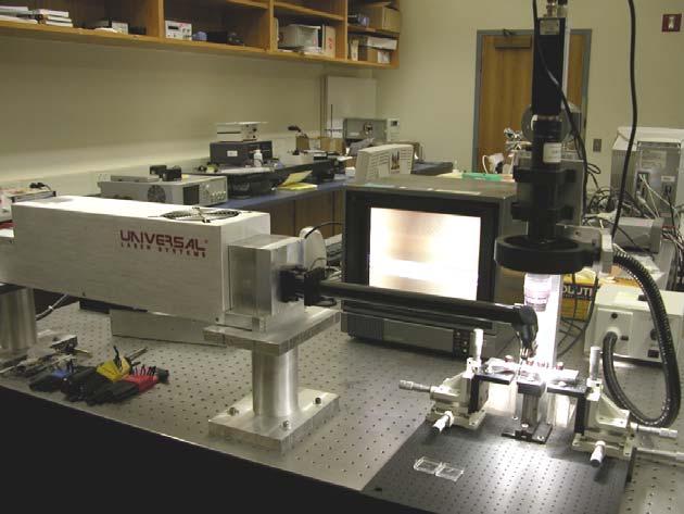
17 8 CO 2 Figure 2.1 Schematic setup of the CO 2 laser based LPFG fabrication system Figure 2.2 Photograph of LPFG fabrication system
18 TRANSMISSION CHARACTERISTICS Typical Transmission Spectra. The transmission characteristics can be measured by the setup shown in Fig The tunable laser served as the light source at one end of the fiber and at the other end an optical power meter was used to detect the power transmitted through the grating. The wavelength stepping of the laser and the power detection of the power meter were coordinated by a computer. The typical transmission spectrum of the fabricated LPFG with a period of 535μm is shown in Fig The curve with black square dots is the resonance peak corresponding to the energy coupling from the fundamental core mode to the 5th cladding mode, while the curve with circles is the numerical simulation calculated based on an analytical modal following Ref. [34, 35]. The spectrum indicated a low loss (<1dB), a narrow Full-Width-at-Half- Maximum (FWHM <7nm) and a high resonance strength (>25dB) of the fabricated LPFG. Figure 2.3 shows that the measured transmission spectrum was in a good agreement with the simulated. Figure 2.3 Measured and simulated transmission spectra of a LPFG with a period of 535μm
19 Typical Transmission Spectra with Different Periods. As shown in Fig. 2.4, by varying the grating period from 505 to 545μm, it is possible to effectively change the resonance wavelength of the LPFG from 1520 to 1640nm, which was mainly limited by the tuning range of the tunable laser. It is possible to further expand the resonance wavelength beyond the 1520 to 1640nm range. According to Eq. 1.2, since the effective refractive indices for both core mode and cladding mode are fixed after fabrication, the resonance wavelength is linearly proportional to the grating period. This linear relation was confirmed by the experiments as shown in Fig Wavelength (nm) Figure 2.4 LPFG transmission spectra with different periods
20 11 Resonance wavelength (nm) Period (um ) Figure 2.5 Resonance wavelength as a function of period 2.3. SUMMARY In this section, the system and procedure for fabricating CO 2 -laser-induced highperformance LPFGs were discussed. The typical transmission spectrum showed a low loss (<1dB), a narrow Full-Width-at-Half-Maximum (FWHM <7nm) and a high resonance strength (>25dB), which was adequate for most communication and sensing applications. The experimental data also confirmed that the resonance wavelength of CO 2 -laser-induced LPFG varied linearly with the grating period. This linear relation can be used to guide the fabrication of LPFGs with any desired resonance wavelength.
21 12 3. HIGH TEMPERATURE PERFORMANCE AND IMPROVEMENT 3.1. HIGH TEMPERATURE SURVIVABILITY To test the temperature survivability and sensitivity of the fabricated LPFGs, a LPFG was installed into an electric furnace and increased the temperature from 100 C to 800 C. The LPFGs used in the experience were fabricated with the same period of 500μm in Corning SMF-28 fiber. The temperature was held for one hour and measured the transmission spectrum of the LPFG at each 100 C increment as shown in Fig The grating transmission spectrum maintained the similar characteristics (e.g., strength and width) in all the temperatures except that the resonance wavelength of the LPFG moved to the long wavelength region when the temperature increased as shown in Fig. 3.1(a). Fig. 3.1(b) shows the resonant wavelength of the LPFG as a function of temperature. The test results clearly demonstrated that the LPFG successfully survived high temperatures up to 800 C. The results also indicated that the resonant wavelength was a linear function of temperature. This linear relation can be explained by the Eq. 1.2, where the grating period increased with the increase of temperature due to thermal expansion of the optical fiber Transimission (db) C 300C 400C 500C 600C 700C 800C Increasing Wavelength (nm) Peak Wavelength (nm) Temperature (Degree C) Figure 3.1 Test of LPFG at various temperatures (a) LPFG transmission spectra at different temperatures (b) resonance wavelength as a function of temperature
22 THERMO STABILITY AND IMPROVEMENT Annealing. The stability of the LPFG is a concern when it is designed and fabricated for high temperature applications. It is highly desired that the resonance peak of the grating does not drift when the grating is exposed to a high temperature environment for a long period of time. However, due to the fact that the refractive index change is caused by thermal treatment and the inevitable thermal relaxation of the treated glass, it is expected that the resonance wavelength will have a non-reversible drift, especially in a high temperature environment. To evaluate the thermal stability of the fabricated LPFG, a CO 2 laser fabricated LPFG was placed in electric furniture at a temperature of 550ºC. One end of the fiber was fixed to the test chamber (a ¼ inch stainless steel tube) while the other one was set loose so that the thermal expansion of the container itself would not affect the LPFG. As shown in Fig. 3.2, the lower curve with circle is the resonance wavelength as a function of time. A wavelength shift of 25.3nm after 200 hours was observed. It can also be seen that the wavelength change was faster at the beginning and getting slower as the experiment went along, indicating that the thermal stability of the LPFG improved after annealing. However, the improvement was slow and would take a long time to stabilize. 2.9 nm nm nm nm 25.3 nm nm Figure 3.2 Thermo stability tests and improvement
23 Thermal Shock. In the second experiment, a LPFG was heated up to 700ºC for 2 hours, and then, cooled it down to 550ºC and maintained for 200 hours. As shown in Fig. 3.2 (the upper curve), the resonant wavelength still shows a continuous drift towards a shorter wavelength but with a much smaller shift of 2.9nm after 200 hours annealing. The experiment indicates that thermal shock indeed improved the thermo stability of LPFG at high temperatures. To better understand the reason under this thermal shock phenomenon, it is necessary to go to the material fundamentals and the micro structure performance of the quiz. It is believed to be an issue in the future research SUMMARY In this section, the performance of LPFG under high temperatures has been evaluated experimentally. The LPFG successfully survived high temperatures up to 800ºC without performance degradation. Not surprisingly, it was also found that the resonance wavelength of the as-fabricated LPFG has a large non-reversible drift when it was subjected to a long-term high temperature annealing test. However, it has also been found that the thermal drift could be significantly reduced by a simple thermal shock process at an elevated temperature. The improved thermal stability of LPFG is of great importance for applying the device to long-term monitoring in a high temperature environment.
24 15 4. REFRACTIVE INDEX MODULATION MEASUREMENT 4.1. MEASUREMENT THEORY CO 2 Laser Exposure Profile Approximation. It has been explained that the change of refractive index comes mainly from stress relaxation effect of thermal shocks [10, 11]. The amount of refractive index modulation inside a fiber core is one of the most critical variables that determine the transmission characteristic of an LPFG. Accurate knowledge of the CO 2 laser irradiation caused refractive index changes can thus help adjust the laser pulse parameters such as the power and pulse duration to fabricate LPFGs with desired performance. As shown in the inset of Fig. 4.1, the upper figure shows the refractive index distribution profile of laser exposure. Assuming that the change of RI in fiber core is Δn Figure 4.1 Setup schematic of measurement sinusoid-distributed and the highest RI change Δ n happens at the center of laser-exposed fiber area, the change of optical path (OP) induced by one laser shot could be expressed as

25 16 Δ W x OP = Δ nsin( ) dx 0 W π (4.1) where W represents the beam width of the beam shaped line width of laser exposure. Solving the integral in Eq.1, it will be 2WΔn Δ OP = (4.2) π Measurement Principle. The peak refractive index change Δn can be measured using a white light fiber optic Michelson interferometer as schematically shown in Fig A 3dB coupler splits the light from a broadband source into the two fiber arms with cleaved endfaces. The reflections from the two endfaces form the interference signal that is recorded by an optical spectrum analyzer (OSA). One fiber is kept undisturbed to serve as the reference path. The other fiber, with its cladding stripped, is placed on a computer-controlled three-dimensional translation stage to be exposed to CO 2 laser irradiation at different locations. OP 2 Intensity Broadband source OSA 3dB coupler Arm #2 CO 2 laser shots Arm #1 I 2 I 1 Cleaved endfaces λ 1 λ 2 Wavelength OP 1 Interference spectrum Signal processing Figure 4.2 Fiber optic Michelson interferometer to measure refractive index modulation Assuming that the two reflected lights from the cleaved fiber endfaces have the intensities of I 1 and I 2, respectively, the interference signal I generated by these two reflections as collected by OSA is given by:
26 17 4π I = I1+ I2 + I1I2 OP1 OP2 λ 2 sin ( ) (4.3) where OP 1 and OP 2 are the forward propagation optical paths (defined as the product of the length and refractive index of the core) of the two arms, respectively. The optical path difference (OPD) between the two fiber arms is given by OPD = OP 1 OP 2. As shown in Fig. 4.2, the two adjacent valleys at λ 1 and λ 2 in the interference spectrum have a phase difference of 2π, that is: 4π 4π OPD OPD = 2π (4.4) λ λ 1 2 Therefore, the OPD between the two arms can be calculated using the following equation: λ1λ 2 OPD = 2( λ λ ) 1 2 (4.5) It is further assumed that the physical length of the fiber does not vary before and after laser irradiation. Therefore, the change of the OPD between two fiber arms is mainly caused by the laser irradiation induced refractive index change inside the fiber core. For multiple-point laser irradiations (with the same laser conditions) at different locations, the accumulated change in OPD is given by OPD after OPD = mδop (4.6) before Single where m is the number of laser irradiation points on the optical fiber, OPD before and OPD after are the optical path differences before and after the m-point CO 2 laser irradiations, and ΔOP Single is the optical path change induce by single laser shot, denoted in Eq The refractive index modulation Δn can thus be determined based on Eq π ( OPDafter OPD Δn = 2mW before ) (4.7)
27 EXPERIMENT A fiber optic Michelson interferometer was constructed based on Fig The fiber used in the experiment was Corning SMF-28 single mode fiber. The two fibers were cleaved simultaneously to make the initial OPD as small as possible. The broadband source used was made by multiplexing a C-band and an L-band Erbium doped fiber ASE (amplified spontaneous emission) sources, which covered the spectral range from 1530 to 1610nm. The two fiber arms were set relaxed on an air-isolated optical table and aligned in parallel to allow the initial interference spectrum to be recorded by an OSA (HP 70952B). Then one fiber was mounted onto the 3D translation stage and exposed to 150 shots of CO 2 laser irradiations at different locations. The exposure power and duration were set as the same as used in grating fabrication. It is important to note that the distance between two adjacent irradiations was set randomly to avoid grating effect in the interference spectrum. After laser exposures, the interference fringe was recorded again by removing the fiber from the stage and placing the two fibers on the optical table at their marked positions where the initial interference spectrum was taken. Then the process was repeated to increase the number of laser exposure points the same fiber RESULTS AND DISCUSSIONS Figure 4.3 plots the results of this experiment, in which Fig. 4.3(a) shows the initial interference spectrum and those after 150, 300, and 450 points irradiations. Since each laser exposure induced a small amount of power loss, the amplitude of the interference signal was reduced as the number of laser exposures increased. The spectral separation of the two adjacent interference valleys decreased with the number of laser exposures, indicating the increase of the OPD. Figure 4.3(b) plots the OPD as a function of the number of laser exposures. The measured data points fit nicely into a line as predicted. It has been obtained that each laser shot brings a nm change in OPD. Given the W=220µm which is the beam width of the laser, the peak index modulation Δn was calculated to be based on the slope of the line.
28 19 Transmission (mw) beofore Shots After 450 shots Wavelength (nm) OPD (um) Number of laser shots Figure 4.3 Results of refractive index modulation measurement; (a) interference spectra and polynomial fitted curves of various number of laser irradiations; (b) optical path difference as a function of the number of laser exposures The transmission spectrum from modeling with this index modulation value fits nicely with the LPFG spectrum fabricated with the same laser pulse parameters as shown in Fig. 2.3.
29 SUMMARY In conclusion, an interferometric method was developed to measure the refractive index change induced by CO 2 laser irradiation. In this method, the laser-induced refractive index change was assumed to have a sinusoid distribution and each of the laser shot would bring an OPD change. The OPD was measured to be based on the phase shift of the interference fringe. The measured refractive index modulation was used to simulate the LPFG transmission spectrum. The simulation was in a good agreement with the measured transmission spectrum.
30 21 5. APPLICATIONS 5.1. AMBIENT REFRACTIVE INDEX MEASUREMENT Because the phase matching condition depends on the effective indices of the coupled cladding modes, which rely on the difference between the refractive index of the cladding and that of the medium surrounding the cladding, the resonance wavelengths of the LPFG show a dependence upon the refractive index of the medium surrounding cladding. LPFGs can thus be used to monitor the refractive index of the surrounding medium. To investigate the effect of refractive index of the surrounding medium on the resonance wavelength, the LPFG was placed in the air (refractive index =1), water (refractive index = 1.33), acetone (refractive index = ) and isopropanol (refractive index = ) and measured the transmission spectrum of the LPFG, respectively. As shown in Fig. 5.1, the LPFG, fabricated with a period of 530µm using a Corning 0 Simulation Measurements Wavelength shift (nm Transmission (db) Water Air IPA Acetone Wavelength (nm) Refractive index Figure 5.1 LPFG in response to ambient refractive index changes
31 22 SMF-28 fiber, had a resonance wavelength of nm in air. Its resonance wavelength shifted to , , and nm when placed in water, acetone, and isopropanol, respectively. In general, the resonant wavelength shifted towards the short wavelength region as the environmental refractive index increased. Figure 5.1 also plots the simulated resonance wavelength shift, with respect to that in air, as a function of the refractive index of the surrounding environment. The three measurement data points were charted on the simulated curve and found that the measured data were in a good agreement with the numerical simulations PALLADIUM COATED LPFG FOR HYDROGEN SENSING Introduction. Considered as a clean and renewable energy source, hydrogen has become a promising alternative to fossil fuels to solve the energy crisis and pollution problems. Consequently, in-situ monitoring hydrogen concentration has become important for the purposes of process control in hydrogen production and safety guard in hydrogen applications. In the last two decades, great efforts have been devoted into the development and commercialization of electrical type hydrogen sensors. Even though some of them exhibited high sensitivity and fast response time, a main drawback of electrical type sensors is that the use of electricity may lead sparks at the sensing point. As an alternative, optical sensors seem to be more attractive due to the lack of sparking possibilities. Moreover, most optical hydrogen sensors operate in a non-contact mode and can be deployed into regions where common electrical sensors are difficult to reach, especially when an optical fiber is used to transmit the signal [36]. To perform hydrogen sensing, many of these optical sensors use specially designed sensing materials that selectively interact with hydrogen molecules to generate an optical signal [37, 38] Principle of Operation. The hydrogen sensor designed in this work selected palladium (Pd) as the sensing material [39]. When Pd is exposed to hydrogen, hydrogen dissociates into two hydrogen atoms at the Pd surface with an efficient rate. The hydrogen atoms then diffuse into the palladium, resulting in the formation of palladium hydride (PdH). The hydration of Pd is also reversible. When the hydrogen concentration in the environment reduces, the Pd releases the adsorbed hydrogen. The
32 23 hydration leads to an increase in the lattice parameters and consequently a decrease in the volume density of free electrons. As a result, the complex refractive index of the Pd changes, which can be used to monitor the hydrogen concentration in the environment. The unique hydrogen related optical property of Pd can be used to develop a hydrogen sensor when integrated with a photonic device, such as the LPFG described in this thesis. The concept is to coat a thin layer of Pd film on a LPFG. Upon exposure to hydrogen, the coated Pd film changes its refractive index and correspondingly the mode coupling condition, resulting in a shift of the resonance wavelength of the grating. Therefore, by monitoring the resonance wavelength shift, the change of the hydrogen concentration can be accurately detected [40] Experiment Setup. The nanosized Pd thin layer was deposited on LPFG by magnetron sputter deposition. During the deposition, the fiber was rotated periodically in order to prepare the thin film coating with relatively uniform thickness. The schematic of hydrogen concentration sensing system is shown in Fig Figure 5.2 Schematic of Pd-LPFG in-situ measurement for hydrogen concentration sensing
33 24 The Pd coated LPFG was placed in a 1/8-inch stainless steel tube. To simulate the actual application environment, two cylindrical gas tanks were connected to the stainless steel tube through a mixer. One is filled with hydrogen gas, while the other is helium gas. The gas flow rates of these two gases can be controlled individually by adjusting the mass flow controllers to obtain the desired concentration of hydrogen inside the stainless steel tube. The stainless steel tube was hosted inside an electric tubular furnace, by which the environmental temperature can be controlled. During sensor installation, one end of the Pd-coated LPFG sensor was fixed to the stainless steel tube by a gas stopper, while the other end was set free to eliminate stress. The two ends of the fiber were connected to a broadband optical source and an optical spectrum analyzer (OSA), respectively. The resolution bandwidth was set 2nm, while the number of the points taken by OSA within certain wavelength range was set 1000 for each scan. The OSA was connected to a computer, where the transmission spectrum of the LPFG was recorded and analyzed Result and Discussion. Figure 5.3 shows a scanning electronic micrograph (SEM) of the Pd-coated LPFG (Pd-LPFG), indicating a thin layer of uniform, defect-free Pd film has been successfully coated on the LPFG. The high magnification SEM image of the film (Fig. 5.3.b) suggested that the Pd film had a nanostructure with a grain size distribution in the range of 20-30nm. It is preferred that the Pd coating remains in this nanostructure as it facilitates the speed of hydrogen adsorption and desorption. The thickness of the coating can be varied by change the duration of sputtering. In general, a thick coating results in high detection sensitivity. However, thick film will also reduce the speed of detection. Therefore, there is a tradeoff between the speed and sensitivity. Prior to the test of the Pd-LPFG in response to hydrogen, the temperature dependence of the sensor was characterized. In the work, the shift of wavelength was found to be 35 pm/ C. The Pd-LPFG sensor was then tested in the temperatures ranging from 30 to 250 C under various hydrogen concentrations. To minimize the noise influences, each measured transmission spectrum was first partially fitted by a 4-th order polynomial series. The resonance wavelength was then calculated as the tuning point of the fitted polynomial.
 500x magnification (b) 50000x magnification The transmission spectrums of Pd-LPFG in helium and 8% hydrogen at various temperatures")
 indicating the increase of Pd refractive index as a result of")
34 25 (a) (b) Figure 5.3 SEM image of Pd-coated LPFG (a) 500x magnification (b) 50000x magnification The transmission spectrums of Pd-LPFG in helium and 8% hydrogen at various temperatures are shown in Fig. 5.4, where the resonance wavelength clearly shifted towards the short wavelength region (blue shift) indicating the increase of Pd refractive index as a result of hydrogen adsorption into the thin film. Comparing the sensor response at various temperatures, it has been found that the amount of resonance wavelength shift highly depended on the temperature. As the temperature went up, the amount of blue shift decreased in response to 8% hydrogen concentration change. At
35 26 room temperature, 8% hydrogen induced 4.2nm of shift in resonance wavelength. While at 200 C, the same 8% hydrogen only caused about 0.1nm shift Transimission (db) nm Transmission (db) nm -10 In 8% H 2 In He -10 In 8% H 2 In He Wavelength(nm) (a) Wavelength (nm) (b) Transmission (db) Transmission (db) nm In 8% H In He Wavelength (nm) pm In 8% H 2 In He Wavelength (nm) (c) (d) Figure 5.4 Spectrum of LPFG coated with Pd in 8% H 2 and H 2 free atmosphere at (a) room temperature (b) 100 C (c) 150 C (d) 200 C The dependence of resonance wavelength shift as a function of hydrogen concentration at different temperatures is shown in Fig In general, it has been found that the amount of blue shift was almost linearly proportional to the hydrogen concentration up to 16%. However, the sensor response decreased significantly as the temperature increased. This can be explained by the fact that the hydrogen adsorption into the film reduces as the temperature increases. Even at 200 C, 4% hydrogen concentration increment resulted in a10pm shift in the resonance wavelength, which was still detectable using the existing system. However, when testing the sensor at 250 C, the amount of hydrogen dissolved into Pd was too low to cause any observable wavelength
36 27 shift in the hydrogen concentration up to 16%. In conclusion, the tests successfully proved that Pd-LPFG sensor was working properly as expected in the temperature range from 25 C to 200 C Wavelength Shift(nm) o C 150 o C 100 o C % % % % % 10% % % % H2 concentration H 2 concentration Figure 5.5 Wavelength shift as a function of H 2 concentration at various temperatures The temporal characteristic of the Pd-LPFG in response to the hydrogen was also experimentally tested. Figure 5.6 shows the response and recovery time of Pd-LPFG when the sensor was exposed to 4% hydrogen at room temperature and 100 C, respectively. At each temperature, the response time to 4% hydrogen was less than one minute. The uptake time at 100 C was slightly shorter than that at room temperature. Compared to the hydrogen uptake process, the recovery time was much longer. At room temperature, it took about 5 minutes to shift back to the 90% of the original position in pure helium, and about 14 minutes to reach the completely stabilized point. It is worth noting that the response and recovery times also included the time required for the experimental setup to stabilize. At 100 C, the recovery time was much shorter than the case under room temperature. It took about 1 minute for the sensor recover to the 90% of its original value, and less than 5 minute to reach stabilization. The shorter response and
37 28 recovery times of the sensor at a higher temperature can be explained by that fact that the adsorption and desorption of hydrogen are much fast at an elevated temperature as predicted by the thermal dynamics % H % H 2 Wavelength (nm) Wavelength (nm) He 1558 He Time (mins) Time (mins) (a) (b) Figure 5.6 Response time and recovery time of LPFG in 4% H 2 at (a) room temperature (b) 100 o C The repeatability of the Pd-LPFG sensor in response to hydrogen was also experimentally evaluated at room temperature and 100 C, respectively, with the results shown in Fig In each test, the sensor was exposed to 4% hydrogen and recovered by pure helium for 5 cycles. The results indicated no observable difference in either the response time or the amount of wavelength shifts in different cycles, implying that the whole absorption and desorption process was repeatable within accuracy of instruments SUMMARY In this section, two applications of LPFG have been demonstrated. The first application focused on the evaluation of the sensing capability of a bare LPFG towards the ambient refractive index change. the experimental results showed a good agreement with the simulation data. The second application was concentrated on development of a
38 29 Pd-coated LPFG sensor for in-situ monitoring hydrogen concentrations at various temperatures. The sensitivity, response time, temperature dependence, and repeatability % H % H Wavelength (nm) Wavelength (nm) He Time (min) He Time (min) (a) (b) Figure 5.7 Repeatability test of Pd-LPFG at (a) room temperature (b) 100 o C have been systematically evaluated. In general, it has been proved that the Pd-coated LPFG could be used to sensitively monitor the hydrogen concentration in the temperature range of 25 C to 200 C.
39 30 6. CONCLUSION Long period fiber gratings have many unique advantages such as small insertion loss, low retro-reflection, good sensory property and low cost fabrication. People have found many applications in optical fiber communications and in optical fiber sensors. Recently, the potential applications of fiber sensors in high temperature environment have attracted considerable interests. Optical fibers have a proven reputation of being high temperature-tolerant due to its glass nature. In addition, optical fiber sensors possess a key advantage over electronic sensors. It is naturally free from electrical sparks which might lead to a serious explosion under extreme conditions. Therefore, it is a natural path to extend the sensing capabilities of LPFGs to meet the ever increasing needs for sensors that can survive high temperature harsh environment. Most of the existing LPFGs are made by UV laser irradiation. However, the UV induced refractive index changes are found difficult to survive high temperatures. Nowadays, CO 2 lasers have been used for fabricating LPFGs. One of the greatest advantages of using the CO 2 laser irradiation technique is that it is simple and flexible to use but still providing a high thermal stability. The main objective of this thesis is to implement a CO 2 -laser-irradiation-based method to fabricate high performance temperature tolerant LPFGs. The thesis work included the establishment of a computer controlled fabrication system with in-situ signal monitoring capability, the characterization of the fabricated LPFGs, high temperature survival ability and stability test in together with its improvement, the measurement of CO 2 Laser induced refractive index change and LPFG-based chemical sensors for various applications. The major conclusions of the thesis work are summarized as following: The system and procedure for fabricating CO 2 -laser-induced high-performance LPFGs were discussed. The typical transmission spectrum showed a low loss (<1dB), a narrow Full-Width-at-Half-Maximum (FWHM <7nm) and a high resonance strength (>25dB), which was adequate for most communication and sensing applications. The experimental data also confirmed that the resonance wavelength of CO 2 -laser-induced
40 31 LPFG varied linearly with the grating period. This linear relation can be used to guide the fabrication of LPFGs with any desired resonance wavelength. The performance of LPFG under high temperatures has been evaluated experimentally. The LPFG successfully survived high temperatures up to 800ºC without performance degradation. It has been found that the resonance wavelength of the asfabricated LPFG has a large non-reversible drift when it was subjected to a long-term high temperature annealing test. However, it has also been found that the thermal drift could be significantly reduced by a simple thermal shock process at an elevated temperature. The improved thermal stability of LPFG is of great importance for applying the device to long-term monitoring in a high temperature environment. An interferometric method to measure the refractive index change induced by CO 2 laser irradiation has been developed. In this method, the laser-induced refractive index change was assumed to have a sinusoid distribution and each of the laser shot would bring an OPD change. The OPD was measured to be based on the phase shift of the interference fringe. The measured refractive index modulation was used to simulate the LPFG transmission spectrum. The simulation was in a good agreement with the measured transmission spectrum. After all, two applications of LPFG have been demonstrated. The first application focused on the evaluation of the sensing capability of a bare LPFG towards the ambient refractive index change. The experimental results showed a good agreement with the simulation data. The second application was concentrated on development of a Pd-coated LPFG sensor for in-situ monitoring hydrogen concentrations at various temperatures. The sensitivity, response time, temperature dependence, and repeatability have been systematically evaluated. In general, it has been proved that the Pd-coated LPFG could be used to sensitively monitor the hydrogen concentration in the temperature range of 25 C to 200 C. Till now, the high temperature chemical sensing capability has been well proven. The next step will be establishing a more detailed model consisting of the outside layer modes, which will make it possible to find out the quantities relation between outside layer refractive index change and the resonance wavelength shift. Meanwhile the multi layer model will help understand the absorption and desportion process better. This
Simultaneous measurement of temperature and strain by three-section phase-shift long period fiber grating
 Scholars' Mine Masters Theses Student Research & Creative Works Fall 211 Simultaneous measurement of temperature and strain by three-section phase-shift long period fiber grating Hongbiao Duan Follow this
Fabrication of Long-Period Fiber Gratings by CO 2 Laser Irradiations for High Temperature Applications
 Fabrication of Long-Period Fiber Gratings by CO 2 Laser Irradiations for High Temperature Applications Tao Wei a, John Montoya a, Jian Zhang b,junhang Dong b, Hai Xiao a* a Department of Electrical and
CHIRPED FIBER BRAGG GRATING (CFBG) BY ETCHING TECHNIQUE FOR SIMULTANEOUS TEMPERATURE AND REFRACTIVE INDEX SENSING
 BY ETCHING TECHNIQUE FOR SIMULTANEOUS TEMPERATURE AND REFRACTIVE INDEX SENSING") CHIRPED FIBER BRAGG GRATING (CFBG) BY ETCHING TECHNIQUE FOR SIMULTANEOUS TEMPERATURE AND REFRACTIVE INDEX SENSING Siti Aisyah bt. Ibrahim and Chong Wu Yi Photonics Research Center Department of Physics,
CHIRPED FIBER BRAGG GRATING (CFBG) BY ETCHING TECHNIQUE FOR SIMULTANEOUS TEMPERATURE AND REFRACTIVE INDEX SENSING Siti Aisyah bt. Ibrahim and Chong Wu Yi Photonics Research Center Department of Physics,
Bragg and fiber gratings. Mikko Saarinen
 Bragg and fiber gratings Mikko Saarinen 27.10.2009 Bragg grating - Bragg gratings are periodic perturbations in the propagating medium, usually periodic variation of the refractive index - like diffraction
CHAPTER 5 FINE-TUNING OF AN ECDL WITH AN INTRACAVITY LIQUID CRYSTAL ELEMENT
 CHAPTER 5 FINE-TUNING OF AN ECDL WITH AN INTRACAVITY LIQUID CRYSTAL ELEMENT In this chapter, the experimental results for fine-tuning of the laser wavelength with an intracavity liquid crystal element
Optical signal processing for fiber Bragg grating based wear sensors
 University of Wollongong Research Online Faculty of Informatics - Papers (Archive) Faculty of Engineering and Information Sciences 2005 Optical signal processing for fiber Bragg grating based wear sensors
Realization of Polarization-Insensitive Optical Polymer Waveguide Devices
 644 Realization of Polarization-Insensitive Optical Polymer Waveguide Devices Kin Seng Chiang,* Sin Yip Cheng, Hau Ping Chan, Qing Liu, Kar Pong Lor, and Chi Kin Chow Department of Electronic Engineering,
Optical RI sensor based on an in-fiber Bragg grating. Fabry-Perot cavity embedded with a micro-channel
 Optical RI sensor based on an in-fiber Bragg grating Fabry-Perot cavity embedded with a micro-channel Zhijun Yan *, Pouneh Saffari, Kaiming Zhou, Adedotun Adebay, Lin Zhang Photonic Research Group, Aston
The absorption of the light may be intrinsic or extrinsic
 Attenuation Fiber Attenuation Types 1- Material Absorption losses 2- Intrinsic Absorption 3- Extrinsic Absorption 4- Scattering losses (Linear and nonlinear) 5- Bending Losses (Micro & Macro) Material
CHAPTER 2 POLARIZATION SPLITTER- ROTATOR BASED ON A DOUBLE- ETCHED DIRECTIONAL COUPLER
 CHAPTER 2 POLARIZATION SPLITTER- ROTATOR BASED ON A DOUBLE- ETCHED DIRECTIONAL COUPLER As we discussed in chapter 1, silicon photonics has received much attention in the last decade. The main reason is
Supplementary Figures
 Supplementary Figures Supplementary Figure 1: Mach-Zehnder interferometer (MZI) phase stabilization. (a) DC output of the MZI with and without phase stabilization. (b) Performance of MZI stabilization
Optical Communications and Networking 朱祖勍. Sept. 25, 2017
 Optical Communications and Networking Sept. 25, 2017 Lecture 4: Signal Propagation in Fiber 1 Nonlinear Effects The assumption of linearity may not always be valid. Nonlinear effects are all related to
SSRG International Journal of Electronics and Communication Engineering (SSRG-IJECE) Volume 2 Issue 6 June 2015
 Volume 2 Issue 6 June 2015") SSRG International Journal of Electronics and Communication Engineering (SSRG-IJECE) Volume Issue 6 June 15 Designing of a Long Period Fiber Grating (LPFG) using Optigrating Simulation Software Mr. Puneet
SSRG International Journal of Electronics and Communication Engineering (SSRG-IJECE) Volume Issue 6 June 15 Designing of a Long Period Fiber Grating (LPFG) using Optigrating Simulation Software Mr. Puneet
A novel tunable diode laser using volume holographic gratings
 A novel tunable diode laser using volume holographic gratings Christophe Moser *, Lawrence Ho and Frank Havermeyer Ondax, Inc. 85 E. Duarte Road, Monrovia, CA 9116, USA ABSTRACT We have developed a self-aligned
Advanced Optical Communications Prof. R. K. Shevgaonkar Department of Electrical Engineering Indian Institute of Technology, Bombay
 Advanced Optical Communications Prof. R. K. Shevgaonkar Department of Electrical Engineering Indian Institute of Technology, Bombay Lecture No. # 27 EDFA In the last lecture, we talked about wavelength
Lithography. 3 rd. lecture: introduction. Prof. Yosi Shacham-Diamand. Fall 2004
 Lithography 3 rd lecture: introduction Prof. Yosi Shacham-Diamand Fall 2004 1 List of content Fundamental principles Characteristics parameters Exposure systems 2 Fundamental principles Aerial Image Exposure
Integrated into Nanowire Waveguides
 Supporting Information Widely Tunable Distributed Bragg Reflectors Integrated into Nanowire Waveguides Anthony Fu, 1,3 Hanwei Gao, 1,3,4 Petar Petrov, 1, Peidong Yang 1,2,3* 1 Department of Chemistry,
 Chapter 5 5.1 What are the factors that determine the thickness of a polystyrene waveguide formed by spinning a solution of dissolved polystyrene onto a substrate? density of polymer concentration of polymer
Improving the Collection Efficiency of Raman Scattering
 PERFORMANCE Unparalleled signal-to-noise ratio with diffraction-limited spectral and imaging resolution Deep-cooled CCD with excelon sensor technology Aberration-free optical design for uniform high resolution
Lecture 6 Fiber Optical Communication Lecture 6, Slide 1
 Lecture 6 Optical transmitters Photon processes in light matter interaction Lasers Lasing conditions The rate equations CW operation Modulation response Noise Light emitting diodes (LED) Power Modulation
UNIT-II : SIGNAL DEGRADATION IN OPTICAL FIBERS
 UNIT-II : SIGNAL DEGRADATION IN OPTICAL FIBERS The Signal Transmitting through the fiber is degraded by two mechanisms. i) Attenuation ii) Dispersion Both are important to determine the transmission characteristics
Rogério Nogueira Instituto de Telecomunicações Pólo de Aveiro Departamento de Física Universidade de Aveiro
 Fiber Bragg Gratings for DWDM Optical Networks Rogério Nogueira Instituto de Telecomunicações Pólo de Aveiro Departamento de Física Universidade de Aveiro Overview Introduction. Fabrication. Physical properties.
An Optical Characteristic Testing System for the Infrared Fiber in a Transmission Bandwidth 9-11μm
 An Optical Characteristic Testing System for the Infrared Fiber in a Transmission Bandwidth 9-11μm Ma Yangwu *, Liang Di ** Center for Optical and Electromagnetic Research, State Key Lab of Modern Optical
7 CHAPTER 7: REFRACTIVE INDEX MEASUREMENTS WITH COMMON PATH PHASE SENSITIVE FDOCT SETUP
 7 CHAPTER 7: REFRACTIVE INDEX MEASUREMENTS WITH COMMON PATH PHASE SENSITIVE FDOCT SETUP Abstract: In this chapter we describe the use of a common path phase sensitive FDOCT set up. The phase measurements
Optimization of Uniform Fiber Bragg Grating Reflection Spectra for Maximum Reflectivity and Narrow Bandwidth
 ISSN (e): 225 35 Vol, 5 Issue,2 February 25 International Journal of Computational Engineering Research (IJCER) Optimization of Uniform Fiber Bragg Grating Reflection Spectra for Maximum Reflectivity and
Spectral Characteristics of Mechanically Induced of Ultralong Period Fiber Gratings (UPFG) as a Pressure Sensor.
 as a Pressure Sensor.") Spectral Characteristics of Mechanically Induced of Ultralong Period Fiber Gratings (UPFG) as a Pressure Sensor. V. Mishra, V V Dwivedi C.U shah University, Surendranagar, Gujrat Abstract. We report here
Spectral Characteristics of Mechanically Induced of Ultralong Period Fiber Gratings (UPFG) as a Pressure Sensor. V. Mishra, V V Dwivedi C.U shah University, Surendranagar, Gujrat Abstract. We report here
NUTC R203. Miniaturized Fiber Inline Fabry-Pérot Interferometer for Chemical Sensing. Tao Wei and Hai Xiao
 Miniaturized Fiber Inline Fabry-Pérot Interferometer for Chemical Sensing by Tao Wei and Hai Xiao NUTC R203 A National University Transportation Center at Missouri University of Science and Technology
High Sensitivity Interferometric Detection of Partial Discharges for High Power Transformer Applications
 High Sensitivity Interferometric Detection of Partial Discharges for High Power Transformer Applications Carlos Macià-Sanahuja and Horacio Lamela-Rivera Optoelectronics and Laser Technology group, Universidad
Fiber-optic Michelson Interferometer Sensor Fabricated by Femtosecond Lasers
 Sensors & ransducers 2013 by IFSA http://www.sensorsportal.com Fiber-optic Michelson Interferometer Sensor Fabricated by Femtosecond Lasers Dong LIU, Ying XIE, Gui XIN, Zheng-Ying LI School of Information
Application Instruction 002. Superluminescent Light Emitting Diodes: Device Fundamentals and Reliability
 I. Introduction II. III. IV. SLED Fundamentals SLED Temperature Performance SLED and Optical Feedback V. Operation Stability, Reliability and Life VI. Summary InPhenix, Inc., 25 N. Mines Road, Livermore,
High Placement Effect of Fibre Bragg Grating Sensor
 High Placement Effect of Fibre Bragg Grating Sensor Suzairi Daud a,b*, Muhammad Safwan Abd Aziz a,b, Ahmad Fakhrurrazi Ahmad Noorden a and Jalil Ali a,b a Laser Center, Ibnu Sina Institute for Scientific
Temperature-Independent Torsion Sensor Based on Figure-of-Eight Fiber Loop Mirror
 (2013) Vol. 3, No. 1: 52 56 DOI: 10.1007/s13320-012-0082-3 Regular Temperature-Independent Torsion Sensor Based on Figure-of-Eight Fiber Loop Mirror Ricardo M. SILVA 1, António B. Lobo RIBEIRO 2, and Orlando
(A) 2f (B) 2 f (C) f ( D) 2 (E) 2
 2f (B) 2 f (C) f ( D) 2 (E) 2") 1. A small vibrating object S moves across the surface of a ripple tank producing the wave fronts shown above. The wave fronts move with speed v. The object is traveling in what direction and with what
1. A small vibrating object S moves across the surface of a ripple tank producing the wave fronts shown above. The wave fronts move with speed v. The object is traveling in what direction and with what
Development of a Low Cost 3x3 Coupler. Mach-Zehnder Interferometric Optical Fibre Vibration. Sensor
 Development of a Low Cost 3x3 Coupler Mach-Zehnder Interferometric Optical Fibre Vibration Sensor Kai Tai Wan Department of Mechanical, Aerospace and Civil Engineering, Brunel University London, UB8 3PH,
Gain-clamping techniques in two-stage double-pass L-band EDFA
 PRAMANA c Indian Academy of Sciences Vol. 66, No. 3 journal of March 2006 physics pp. 539 545 Gain-clamping techniques in two-stage double-pass L-band EDFA S W HARUN 1, N Md SAMSURI 2 and H AHMAD 2 1 Faculty
Basic concepts. Optical Sources (b) Optical Sources (a) Requirements for light sources (b) Requirements for light sources (a)
 Optical Sources (a) Requirements for light sources (b) Requirements for light sources (a)") Optical Sources (a) Optical Sources (b) The main light sources used with fibre optic systems are: Light-emitting diodes (LEDs) Semiconductor lasers (diode lasers) Fibre laser and other compact solid-state
Optical Sources (a) Optical Sources (b) The main light sources used with fibre optic systems are: Light-emitting diodes (LEDs) Semiconductor lasers (diode lasers) Fibre laser and other compact solid-state
Section 2: Lithography. Jaeger Chapter 2. EE143 Ali Javey Slide 5-1
 Section 2: Lithography Jaeger Chapter 2 EE143 Ali Javey Slide 5-1 The lithographic process EE143 Ali Javey Slide 5-2 Photolithographic Process (a) (b) (c) (d) (e) (f) (g) Substrate covered with silicon
Stabilized Interrogation and Multiplexing. Techniques for Fiber Bragg Grating Vibration Sensors
 Stabilized Interrogation and Multiplexing Techniques for Fiber Bragg Grating Vibration Sensors Hyung-Joon Bang, Chang-Sun Hong and Chun-Gon Kim Division of Aerospace Engineering Korea Advanced Institute
EE 233. LIGHTWAVE. Chapter 2. Optical Fibers. Instructor: Ivan P. Kaminow
 EE 233. LIGHTWAVE SYSTEMS Chapter 2. Optical Fibers Instructor: Ivan P. Kaminow PLANAR WAVEGUIDE (RAY PICTURE) Agrawal (2004) Kogelnik PLANAR WAVEGUIDE a = (n s 2 - n c2 )/ (n f 2 - n s2 ) = asymmetry;
High temperature tolerant optical fiber inline microsensors by laser fabrication
 Scholars' Mine Doctoral Dissertations Student Research & Creative Works Fall 2010 High temperature tolerant optical fiber inline microsensors by laser fabrication Tao Wei Follow this and additional works
Nd:YSO resonator array Transmission spectrum (a. u.) Supplementary Figure 1. An array of nano-beam resonators fabricated in Nd:YSO.
 Supplementary Figure 1. An array of nano-beam resonators fabricated in Nd:YSO.") a Nd:YSO resonator array µm Transmission spectrum (a. u.) b 4 F3/2-4I9/2 25 2 5 5 875 88 λ(nm) 885 Supplementary Figure. An array of nano-beam resonators fabricated in Nd:YSO. (a) Scanning electron microscope
a Nd:YSO resonator array µm Transmission spectrum (a. u.) b 4 F3/2-4I9/2 25 2 5 5 875 88 λ(nm) 885 Supplementary Figure. An array of nano-beam resonators fabricated in Nd:YSO. (a) Scanning electron microscope
SUPPRESSION OF THE CLADDING MODE INTERFERENCE IN CASCADED LONG PERIOD FIBER GRATINGS WITH LIQUID CRYSTAL CLADDINGS
 Mol. Cryst. Liq. Cryst., Vol. 413, pp. 399=[2535] 406=[2542], 2004 Copyright # Taylor & Francis Inc. ISSN: 1542-1406 print=1563-5287 online DOI: 10.1080=15421400490438898 SUPPRESSION OF THE CLADDING MODE
Faraday Rotators and Isolators
 Faraday Rotators and I. Introduction The negative effects of optical feedback on laser oscillators and laser diodes have long been known. Problems include frequency instability, relaxation oscillations,
On-chip interrogation of a silicon-on-insulator microring resonator based ethanol vapor sensor with an arrayed waveguide grating (AWG) spectrometer
 spectrometer") On-chip interrogation of a silicon-on-insulator microring resonator based ethanol vapor sensor with an arrayed waveguide grating (AWG) spectrometer Nebiyu A. Yebo* a, Wim Bogaerts, Zeger Hens b,roel Baets
On-chip interrogation of a silicon-on-insulator microring resonator based ethanol vapor sensor with an arrayed waveguide grating (AWG) spectrometer Nebiyu A. Yebo* a, Wim Bogaerts, Zeger Hens b,roel Baets
S-band gain-clamped grating-based erbiumdoped fiber amplifier by forward optical feedback technique
 S-band gain-clamped grating-based erbiumdoped fiber amplifier by forward optical feedback technique Chien-Hung Yeh 1, *, Ming-Ching Lin 3, Ting-Tsan Huang 2, Kuei-Chu Hsu 2 Cheng-Hao Ko 2, and Sien Chi
Characteristics of point-focus Simultaneous Spatial and temporal Focusing (SSTF) as a two-photon excited fluorescence microscopy
 as a two-photon excited fluorescence microscopy") Characteristics of point-focus Simultaneous Spatial and temporal Focusing (SSTF) as a two-photon excited fluorescence microscopy Qiyuan Song (M2) and Aoi Nakamura (B4) Abstracts: We theoretically and experimentally
Characteristics of point-focus Simultaneous Spatial and temporal Focusing (SSTF) as a two-photon excited fluorescence microscopy Qiyuan Song (M2) and Aoi Nakamura (B4) Abstracts: We theoretically and experimentally
Thermal tuning of volume Bragg gratings for high power spectral beam combining
 Thermal tuning of volume Bragg gratings for high power spectral beam combining Derrek R. Drachenberg, Oleksiy Andrusyak, Ion Cohanoschi, Ivan Divliansky, Oleksiy Mokhun, Alexei Podvyaznyy, Vadim Smirnov,
Thin-Core-Fiber-Based Long-Period Fiber Grating for High-Sensitivity Refractive Index Measurement
 Thin-Core-Fiber-Based Long-Period Fiber Grating for High-Sensitivity Refractive Index Measurement Volume 7, Number 6, December 2015 Cailing Fu Xiaoyong Zhong Changrui Liao Yiping Wang Ying Wang Jian Tang
Introduction Fundamentals of laser Types of lasers Semiconductor lasers
 ECE 5368 Introduction Fundamentals of laser Types of lasers Semiconductor lasers Introduction Fundamentals of laser Types of lasers Semiconductor lasers How many types of lasers? Many many depending on
Title: Laser marking with graded contrast micro crack inside transparent material using UV ns pulse
 Cover Page Title: Laser marking with graded contrast micro crack inside transparent material using UV ns pulse laser Authors: Futoshi MATSUI*(1,2), Masaaki ASHIHARA(1), Mitsuyasu MATSUO (1), Sakae KAWATO(2),
Photonics and Optical Communication
 Photonics and Optical Communication (Course Number 300352) Spring 2007 Dr. Dietmar Knipp Assistant Professor of Electrical Engineering http://www.faculty.iu-bremen.de/dknipp/ 1 Photonics and Optical Communication
Optical Amplifiers Photonics and Integrated Optics (ELEC-E3240) Zhipei Sun Photonics Group Department of Micro- and Nanosciences Aalto University
 Zhipei Sun Photonics Group Department of Micro- and Nanosciences Aalto University") Photonics Group Department of Micro- and Nanosciences Aalto University Optical Amplifiers Photonics and Integrated Optics (ELEC-E3240) Zhipei Sun Last Lecture Topics Course introduction Ray optics & optical
Photonics Group Department of Micro- and Nanosciences Aalto University Optical Amplifiers Photonics and Integrated Optics (ELEC-E3240) Zhipei Sun Last Lecture Topics Course introduction Ray optics & optical
Opto-VLSI-based reconfigurable photonic RF filter
 Research Online ECU Publications 29 Opto-VLSI-based reconfigurable photonic RF filter Feng Xiao Mingya Shen Budi Juswardy Kamal Alameh This article was originally published as: Xiao, F., Shen, M., Juswardy,
3550 Aberdeen Ave SE, Kirtland AFB, NM 87117, USA ABSTRACT 1. INTRODUCTION
 Beam Combination of Multiple Vertical External Cavity Surface Emitting Lasers via Volume Bragg Gratings Chunte A. Lu* a, William P. Roach a, Genesh Balakrishnan b, Alexander R. Albrecht b, Jerome V. Moloney
MASSACHUSETTS INSTITUTE OF TECHNOLOGY Department of Electrical Engineering and Computer Science
 Student Name Date MASSACHUSETTS INSTITUTE OF TECHNOLOGY Department of Electrical Engineering and Computer Science 6.161 Modern Optics Project Laboratory Laboratory Exercise No. 6 Fall 2010 Solid-State
PERFORMANCE OF PHOTODIGM S DBR SEMICONDUCTOR LASERS FOR PICOSECOND AND NANOSECOND PULSING APPLICATIONS
 PERFORMANCE OF PHOTODIGM S DBR SEMICONDUCTOR LASERS FOR PICOSECOND AND NANOSECOND PULSING APPLICATIONS By Jason O Daniel, Ph.D. TABLE OF CONTENTS 1. Introduction...1 2. Pulse Measurements for Pulse Widths
Elements of Optical Networking
 Bruckner Elements of Optical Networking Basics and practice of optical data communication With 217 Figures, 13 Tables and 93 Exercises Translated by Patricia Joliet VIEWEG+ TEUBNER VII Content Preface
Supplementary Figure 1. GO thin film thickness characterization. The thickness of the prepared GO thin
 Supplementary Figure 1. GO thin film thickness characterization. The thickness of the prepared GO thin film is characterized by using an optical profiler (Bruker ContourGT InMotion). Inset: 3D optical
The electric field for the wave sketched in Fig. 3-1 can be written as
 ELECTROMAGNETIC WAVES Light consists of an electric field and a magnetic field that oscillate at very high rates, of the order of 10 14 Hz. These fields travel in wavelike fashion at very high speeds.
ADVANCES in NATURAL and APPLIED SCIENCES
 ADVANCES in NATURAL and APPLIED SCIENCES ISSN: 1995-0772 Published BYAENSI Publication EISSN: 1998-1090 http://www.aensiweb.com/anas 2017 June 11(8): pages 639-644 Open Access Journal Design And Implementation
The Effect of Radiation Coupling in Higher Order Fiber Bragg Gratings
 PIERS ONLINE, VOL. 3, NO. 4, 27 462 The Effect of Radiation Coupling in Higher Order Fiber Bragg Gratings Li Yang 1, Wei-Ping Huang 2, and Xi-Jia Gu 3 1 Department EEIS, University of Science and Technology
Guided Propagation Along the Optical Fiber. Xavier Fernando Ryerson Comm. Lab
 Guided Propagation Along the Optical Fiber Xavier Fernando Ryerson Comm. Lab The Nature of Light Quantum Theory Light consists of small particles (photons) Wave Theory Light travels as a transverse electromagnetic
Ratiometric Wavelength Monitor Based on Singlemode-Multimode-Singlemode Fiber Structure
 Dublin Institute of Technology ARROW@DIT Articles School of Electrical and Electronic Engineering 8-1-1 Ratiometric Wavelength Monitor Based on Singlemode-Multimode-Singlemode Fiber Structure Agus Hatta
Optical Fibre-based Environmental Sensors Utilizing Wireless Smart Grid Platform
 Optical Fibre-based Environmental Sensors Utilizing Wireless Smart Grid Platform Minglong Zhang 1, Kin Kee Chow 2*, and Peter Han Joo Chong 1 1 Department of Electrical and Electronic Engineering, Auckland
Electronically switchable Bragg gratings provide versatility
 Page 1 of 5 Electronically switchable Bragg gratings provide versatility Recent advances in ESBGs make them an optimal technological fabric for WDM components. ALLAN ASHMEAD, DigiLens Inc. The migration
Dispersion Measurements of High-Speed Lightwave Systems
 Lightwave Symposium Dispersion Measurements of Presented by Johann L. Fernando, Product Manager 3-1 Topics Chromatic dispersion concepts Agilent 86037C Chromatic Dispersion Measurement System Polarization
Ph 77 ADVANCED PHYSICS LABORATORY ATOMIC AND OPTICAL PHYSICS
 Ph 77 ADVANCED PHYSICS LABORATORY ATOMIC AND OPTICAL PHYSICS Diode Laser Characteristics I. BACKGROUND Beginning in the mid 1960 s, before the development of semiconductor diode lasers, physicists mostly
Study of Multiwavelength Fiber Laser in a Highly Nonlinear Fiber
 Study of Multiwavelength Fiber Laser in a Highly Nonlinear Fiber I. H. M. Nadzar 1 and N. A.Awang 1* 1 Faculty of Science, Technology and Human Development, Universiti Tun Hussein Onn Malaysia, Johor,
Comparison of FRD (Focal Ratio Degradation) for Optical Fibres with Different Core Sizes By Neil Barrie
 for Optical Fibres with Different Core Sizes By Neil Barrie") Comparison of FRD (Focal Ratio Degradation) for Optical Fibres with Different Core Sizes By Neil Barrie Introduction The purpose of this experimental investigation was to determine whether there is a dependence
Comparison of FRD (Focal Ratio Degradation) for Optical Fibres with Different Core Sizes By Neil Barrie Introduction The purpose of this experimental investigation was to determine whether there is a dependence
Fiber Optic Communication Systems. Unit-05: Types of Fibers. https://sites.google.com/a/faculty.muet.edu.pk/abdullatif
 Unit-05: Types of Fibers https://sites.google.com/a/faculty.muet.edu.pk/abdullatif Department of Telecommunication, MUET UET Jamshoro 1 Optical Fiber Department of Telecommunication, MUET UET Jamshoro
Week IX: INTERFEROMETER EXPERIMENTS
 Week IX: INTERFEROMETER EXPERIMENTS Notes on Adjusting the Michelson Interference Caution: Do not touch the mirrors or beam splitters they are front surface and difficult to clean without damaging them.
Department of Electrical Engineering and Computer Science
 MASSACHUSETTS INSTITUTE of TECHNOLOGY Department of Electrical Engineering and Computer Science 6.161/6637 Practice Quiz 2 Issued X:XXpm 4/XX/2004 Spring Term, 2004 Due X:XX+1:30pm 4/XX/2004 Please utilize
Fiber Optics. Laboratory exercise
 Fiber Optics V 1/27/2012 Laboratory exercise The purpose of the present laboratory exercise is to get practical experience in handling optical fiber. In particular we learn how to cleave the fiber and
Temporal coherence characteristics of a superluminescent diode system with an optical feedback mechanism
 VI Temporal coherence characteristics of a superluminescent diode system with an optical feedback mechanism Fang-Wen Sheu and Pei-Ling Luo Department of Applied Physics, National Chiayi University, Chiayi
Ring cavity tunable fiber laser with external transversely chirped Bragg grating
 Ring cavity tunable fiber laser with external transversely chirped Bragg grating A. Ryasnyanskiy, V. Smirnov, L. Glebova, O. Mokhun, E. Rotari, A. Glebov and L. Glebov 2 OptiGrate, 562 South Econ Circle,
Supplementary Figure S1. Schematic representation of different functionalities that could be
 Supplementary Figure S1. Schematic representation of different functionalities that could be obtained using the fiber-bundle approach This schematic representation shows some example of the possible functions
OPTICAL NETWORKS. Building Blocks. A. Gençata İTÜ, Dept. Computer Engineering 2005
 OPTICAL NETWORKS Building Blocks A. Gençata İTÜ, Dept. Computer Engineering 2005 Introduction An introduction to WDM devices. optical fiber optical couplers optical receivers optical filters optical amplifiers
Progress In Electromagnetics Research C, Vol. 15, 37 48, 2010 TEMPERATURE INSENSITIVE BROAD AND FLAT GAIN C-BAND EDFA BASED ON MACRO-BENDING
 Progress In Electromagnetics Research C, Vol. 15, 37 48, 2010 TEMPERATURE INSENSITIVE BROAD AND FLAT GAIN C-BAND EDFA BASED ON MACRO-BENDING P. Hajireza Optical Fiber Devices Group Multimedia University
R. J. Jones Optical Sciences OPTI 511L Fall 2017
 R. J. Jones Optical Sciences OPTI 511L Fall 2017 Semiconductor Lasers (2 weeks) Semiconductor (diode) lasers are by far the most widely used lasers today. Their small size and properties of the light output
Student Research & Creative Works
 Scholars' Mine Masters Theses Student Research & Creative Works Summer 2014 Microwave assisted reconstruction of optical interferograms for distributed fiber optics sensing & characterization of PCB dielectric
Keysight Technologies Using a Wide-band Tunable Laser for Optical Filter Measurements
 Keysight Technologies Using a Wide-band Tunable Laser for Optical Filter Measurements Article Reprint NASA grants Keysight Technologies permission to distribute the article Using a Wide-band Tunable Laser
Vertical External Cavity Surface Emitting Laser
 Chapter 4 Optical-pumped Vertical External Cavity Surface Emitting Laser The booming laser techniques named VECSEL combine the flexibility of semiconductor band structure and advantages of solid-state
Far field intensity distributions of an OMEGA laser beam were measured with
 Experimental Investigation of the Far Field on OMEGA with an Annular Apertured Near Field Uyen Tran Advisor: Sean P. Regan Laboratory for Laser Energetics Summer High School Research Program 200 1 Abstract
Analysis of the Tunable Asymmetric Fiber F-P Cavity for Fiber Strain Sensor Edge-Filter Demodulation
 PHOTONIC SENSORS / Vol. 4, No. 4, 014: 338 343 Analysis of the Tunable Asymmetric Fiber F-P Cavity for Fiber Strain Sensor Edge-Filter Demodulation Haotao CHEN and Youcheng LIANG * Guangzhou Ivia Aviation
Individually ventilated cages microclimate monitoring using photoacoustic spectroscopy
 Individually ventilated cages microclimate monitoring using photoacoustic spectroscopy Jean-Philippe Besson*, Marcel Gyger**, Stéphane Schilt *, Luc Thévenaz *, * Nanophotonics and Metrology Laboratory
Model Series 400X User s Manual. DC-100 MHz Electro-Optic Phase Modulators
 Model Series 400X User s Manual DC-100 MHz Electro-Optic Phase Modulators 400412 Rev. D 2 Is a registered trademark of New Focus, Inc. Warranty New Focus, Inc. guarantees its products to be free of defects
NEW LASER ULTRASONIC INTERFEROMETER FOR INDUSTRIAL APPLICATIONS B.Pouet and S.Breugnot Bossa Nova Technologies; Venice, CA, USA
 NEW LASER ULTRASONIC INTERFEROMETER FOR INDUSTRIAL APPLICATIONS B.Pouet and S.Breugnot Bossa Nova Technologies; Venice, CA, USA Abstract: A novel interferometric scheme for detection of ultrasound is presented.
Stable dual-wavelength oscillation of an erbium-doped fiber ring laser at room temperature
 Stable dual-wavelength oscillation of an erbium-doped fiber ring laser at room temperature Donghui Zhao.a, Xuewen Shu b, Wei Zhang b, Yicheng Lai a, Lin Zhang a, Ian Bennion a a Photonics Research Group,
Hybrid Integration Technology of Silicon Optical Waveguide and Electronic Circuit
 Hybrid Integration Technology of Silicon Optical Waveguide and Electronic Circuit Daisuke Shimura Kyoko Kotani Hiroyuki Takahashi Hideaki Okayama Hiroki Yaegashi Due to the proliferation of broadband services
Multi-wavelength laser generation with Bismuthbased Erbium-doped fiber
 Multi-wavelength laser generation with Bismuthbased Erbium-doped fiber H. Ahmad 1, S. Shahi 1 and S. W. Harun 1,2* 1 Photonics Research Center, University of Malaya, 50603 Kuala Lumpur, Malaysia 2 Department
Isolator-Free 840-nm Broadband SLEDs for High-Resolution OCT
 Isolator-Free 840-nm Broadband SLEDs for High-Resolution OCT M. Duelk *, V. Laino, P. Navaretti, R. Rezzonico, C. Armistead, C. Vélez EXALOS AG, Wagistrasse 21, CH-8952 Schlieren, Switzerland ABSTRACT
Section 2: Lithography. Jaeger Chapter 2 Litho Reader. The lithographic process
 Section 2: Lithography Jaeger Chapter 2 Litho Reader The lithographic process Photolithographic Process (a) (b) (c) (d) (e) (f) (g) Substrate covered with silicon dioxide barrier layer Positive photoresist
OPTI510R: Photonics. Khanh Kieu College of Optical Sciences, University of Arizona Meinel building R.626
 OPTI510R: Photonics Khanh Kieu College of Optical Sciences, University of Arizona kkieu@optics.arizona.edu Meinel building R.626 Announcements Homework #3 is due today No class Monday, Feb 26 Pre-record
Tunable Color Filters Based on Metal-Insulator-Metal Resonators
 Chapter 6 Tunable Color Filters Based on Metal-Insulator-Metal Resonators 6.1 Introduction In this chapter, we discuss the culmination of Chapters 3, 4, and 5. We report a method for filtering white light
Single-photon excitation of morphology dependent resonance
 Single-photon excitation of morphology dependent resonance 3.1 Introduction The examination of morphology dependent resonance (MDR) has been of considerable importance to many fields in optical science.
This document is downloaded from DR-NTU, Nanyang Technological University Library, Singapore.
 This document is downloaded from DR-NTU, Nanyang Technological University Library, Singapore. Title Miniature photonic crystal optical fiber humidity sensor based on polyvinyl alcohol Author(s) Citation
Chapter 1 Introduction
 Chapter 1 Introduction 1-1 Preface Telecommunication lasers have evolved substantially since the introduction of the early AlGaAs-based semiconductor lasers in the late 1970s suitable for transmitting
Intensity-modulated and temperature-insensitive fiber Bragg grating vibration sensor
 Intensity-modulated and temperature-insensitive fiber Bragg grating vibration sensor Lan Li, Xinyong Dong, Yangqing Qiu, Chunliu Zhao and Yiling Sun Institute of Optoelectronic Technology, China Jiliang
Instructions for the Experiment
 Instructions for the Experiment Excitonic States in Atomically Thin Semiconductors 1. Introduction Alongside with electrical measurements, optical measurements are an indispensable tool for the study of
Stabilisation of Linear-cavity Fibre Laser Using a Saturable Absorber
 Edith Cowan University Research Online ECU Publications 2011 2011 Stabilisation of Linear-cavity Fibre Laser Using a Saturable Absorber David Michel Edith Cowan University Feng Xiao Edith Cowan University