Micro-controller X Model: PXE4. Operation Manual. INP-TN5A1887a-E
|
|
|
- Elvin Nichols
- 5 years ago
- Views:
Transcription
1 Micro-controller X Model: PXE4 Operation Manual INP-TN5A1887a-E 2
2 BEFORE USE Thank you very much for purchasing Fuji s digital controller. (1) Be sure to read this manual and grasp the concept before operating the instrument. (2) The purpose of this manual is to provide detailed information on the function of the instrument. It does not guarantee that the instrument conforms to the specific purpose of the customer. (3) No part or the whole of this manual may be reproduced without Fuji Electric permission. (4) The contents of this manual may be changed without prior notice. Note Sufficient care has been taken to assure the accuracy of this manual. Please note that Fuji Electric is not responsible for any damage, including indirect damage, resulting from an error in writing, missing information, or the use of the information described in the manual. 2
3
4 Warning Installation and wiring This controller designed to be installed at the following conditions. Operating temperature Operating humidity 90%RH or less (Non condensation) Installation category II Pollution degree 2 Conforming to IEC The controller must be installed such that with the exception of the connection to the mains,creepage and clearance distances shown in the table below are maintained between the temperature probe and any other assemblies which use or generate a voltage shown in the table below. Failure to maintain these minimum distances would invalidate the EN safety approval. Voltage used or generated by any assemblies Clearance (mm) Creepage (mm) Up to 50Vrms or Vdc Up to 100Vrms or Vdc Up to 150Vrms or Vdc Up to 300Vrms or Vdc Above 300Vrms or Vdc Contact with our sales office. If the voltage shown above exceeds 50Vdc (i.e. hazardous voltage), the basic insulation is required between all terminals of this controller and the ground, and supplementary insulation is required for the alarm output. Isolation class of this controller is as shown below. Be sure to check that the isolation class of the controller satisfies your requirements before installation. Mains (Power source) Control output (relay output) Alarm output (AL1) Alarm output (AL2) Basic insulation Non-insulation Measured value input Internal circuit SSR/SSC driving output If there is a danger of a serious accident resulting from a failure or a defect in this unit, provide the unit with an appropriate external protective circuit to prevent an accident. The unit is normally supplied without a power switch and fuses. Make wiring so that the fuse is placed between the main power supply switch and this controller. (Main power supply: 2 pole breaker, fuse rating: 250V, 1A) A switch (or a circuit-breaker) must be included in the installation. A switch (or a circuit-breaker) must be suitably located and easily reached. A switch (or a circuit-breaker) must be marked as the disconnecting device for this equipment. Supply wiring shall be prepared by installers in accordance with national regulations. A switch (or a circuit-breaker) must be included in the installation. A switch (or a circuit-breaker) must be suitably located and easily reached. A switch (or a circuit-breaker) must be marked as the disconnecting device for this equipment. Supply wiring shall be prepared by installers in accordance with national regulations. When wiring the power supply terminal, use vinyl insulated 600 volt cable or equivalent. To avoid the damage and failure of controller, supply the power voltage fitting to the rating. To avoid an electric shock and controller failure, do not turn ON the power before all wiring is completed. Be sure to check that the distance is kept to avoid electric shock or firing before turning the power ON. Keep away from terminals while the circuit is energized in order to avoid an electric shock and a malfunction. Never attempt to disassemble, fabricate, modify, or repair this unit because tampering with the unit may result in a malfunction, electric shock, or a fire. Output relay is the part has a limited life. When output relay contact comes to the end of its life, it might remain on-state, or off-state. For safety, use a protective circuit outside. 4
5
6 Precautions in wiring connection For the thermocouple sensor type, use thermocouple compensation wires for wiring. For the RTD type, use a wiring material with a small lead wire resistance and no resistance differentials among three wires. Keep input lines away from power line and load line to avoid the influence from noise induced. For the input and output signal lines, be sure to use shielded wires and keep them away from each other. If a noise level is excessive in the power supply, the additional installation of an insulating transformer and the use of a noise filter are recommended. Make sure that the noise filter is installed to a place such as a panel that is properly grounded. The wiring between the noise filter output terminal and the instrument power supply terminal should be made as short as possible. None of fuses or switches should be installed to the wiring on the noise filter output side because the filter effect will be degraded by such a installation. A better anti-noise effect can be expected by using stranded power supply cable for the instrument. (The shorter the stranding pitch is, the better the anti-noise effect can be expected.) A setup time is required for the contact output when the power is turned on. If the contact output is used as a signal for an external interlock circuit, use a delay relay at the same time. Use the auxiliary relay since the life is shortened if full capacity load is connected to the output relay. SSR/SSC drive output type is preferred if the output operations occur frequently. [Proportional interval] relay output: 30 seconds or more, SSR/SSC: one second or more If inductive load such as magnetic switches connected as a relay output load, it is recommended to use serge absorber to protect a contact from switching serge and keep a longer life. Recommended spec of serge absorber Voltage 100V 200V Varistor voltage 240V 470V Where to install: Connect it between contacts of the relay control output. Example) Serge absorber. connection Requirement for key operation/operation in abnormalities Prior to the operation, be sure to check alarm functions, since a failure in the proper setting will result in a failure in the proper output of an alarm in case of an abnormality. A display of UUUU or LLLL will appear in case of a break in the input. Be sure to turn off the power when a sensor is replaced. Others Do not use organic solvents such as alcohol and benzine to wipe this controller. Use a neutral detergent for wiping the controller. 6
7 Table of Contents BEFORE USE...2 Safety Precautions Part Names and Functions Operations Basic operation Parameter Overview Parameter list Setup procedure Steps for Setting Parameters Example for parameter setting Parameter functions and method of settings...18 Method of setting the SV...18 Standby...19 Alarm latch cancel...20 Auto-tuning...21 Alarm 1 and Upper limit of alarm 1 and Lower limit of alarm 1 and Key lock...24 Proportional band, Integration time,derivative time...25 HYS mode at ON/OFF control...28 Output convergence value...29 Anti-reset windup...30 SV (Setting value) lower limit...31 SV (Setting value) upper limit...31 Control method...32 Cycle time of control output...34 Normal/reverse action...35 SV (Setting value) offset...36 Input type...37 PV lower limit...38 PV upper limit...38 Decimal point position...39 PV (process value) offset...40 Time constant of input filter...41 FALT output...42 Output upper/lower limit...43 MV limit type...44 Alarm type...45 Delay time...48 Alarm Hysteresis...48 Alarm 1 and 2 options
8 Loop break detection time...51 Loop break detection band...51 Changeover of parameter display...52 Soft-start...53 Soft-start duration...53 Alarm action during standby...54 Auto display off...55 Display off...56 PV blink setting during input error...57 Alarm display...58 Output (MV) display...59 User key lock...60 Parameter reset Troubleshooting
9 Model Code Configuration PXE T Y 1 Y E Digit Specification 4 <Front dimensions> 48 X 48mm 5 <Input signal> Thermocouple RTD ( C) Thermocouple RTD ( F) 6 <Control output> Relay contact output SSR/SSC driving output <Revision code> <Optional specifications> Alarm (1 pc.) Alarm (2 pc.) <Power supply voltage, Instruction manual> 100 to 240V AC, Japanese/English/Chinese Note Input signal, measurement range, and set value at the time of deliver are as follows. Thermocouple K, Measurement range; 0 to 400 C, Set value; 0C Input signal of the thermocouple and the RTD can be switched by key operation on the front panel. 9
10
11
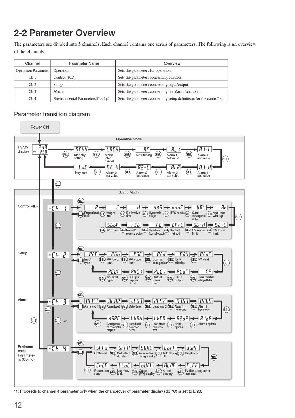
12
13 2-3 Parameter list Operation parameter Display Parameter name Description Setting range PV/SV display Standby Alarm latch cancel Auto-tuning Default setting Conditions for parameters to appear Displays the process value (PV) and the setting value (SV). Specifys the setting 0.00 to %FS 18 value (SV). Switches between RUN and Standby for control. Cancels the alarm latch. The set value will be automatically restored to OFF. Starts and stops the auto-tuning. : control Standby : control RUN (control and alarm output are in normal operation) : Keeps the alarm latch : Opens up the alarm latch : Stop : Normal auto-tuning : Low-PV autp-tuning Note page 19 When the alarm latch function is used. When the control method (CTrL) is PID or FUZY Alarm set value Sets the operation points of alarm. When the alarm type is absolute value: 0.00 to100.00%fs When the alarm type is deviation: to100.00%fs 2.50%FS When alarm type is set to between 1 and Industrial 11 or between 16 and value. 31. *23 Key lock Sets the key lock to prevent operational error. : : Change of setting is available from the face panel. All parameters can not bea changed. Invalid of AT (Block key + Down key) and standby (Block key + Up key) switchover : Only SV setting can be changed. Invalid of AT (Block key + Down key) and standby (Block key + Up key) switchover 24 Channel 1 parameter Display Parameter name Description Setting range Proportional band Integral time Derivative time Hysteresis range for ON/OFF control HYS (Hysteresis) mode Output convergence value Anti-reset windup SV (Setting Value) lower limit SV (Setting Value) upper limit Control method Cycle time of control output Normal/reverse action SV (Setting Value) offset Default setting Sets the proportional band of PID 0.1 to 999.9% 5.0% parameter. Sets the integral time of PID parameter Sets the derivative time of PID parameter Selects the hysteresis range for ON/OFF control. Selects the hysteresis operation point at ON/OFF control. Sets the offset value to be add to MV. 0 to 3200 seconds 0.0 to seconds 0 to 50%FS Specify the range of integral 0 to 100%FS action Sets the lower limit of the SV. Sets the upper limit of the SV. Selects the control method. Sets the cycle time of control output. Switches between normal and reverse action. Sets the offset value to be added to SV. : Starts the two-position control at the values of SV+HYS/2 and SV-HYS/2. : Starts the two-position control at the values of SV+HYS and SV-HYS. 240 seconds 60.0 seconds 0.25% FS to 100.0% 0.0% 0 to 100%FS 0 to 100%FS : ON/OFF control. : Normal PID operation. : Fuzzy control. 1 to 150 seconds : Reverse action : Normal action 100% FS 0% FS 100% FS relay: 30 seconds SSR: 2 seconds -50 to 50%FS 0%FS Conditions for parameters to appear When the control method (CTrL) is PID or FUZY. When the control method (CTrL) is PID or FUZY. When the control method (CTrL) is PID or FUZY. Note When the control Industrial method (CTrL) is value. ONOF. When the changeover of parameter display (dspc) is EnG and the control method (CTrL) is ONOF. When the control method (CTrL) is PID or FUZY. When the changeover of parameter display (dspc) is EnG and Industrial the control method value. (CTrL) is PID or FUZY. When the changeover Industrial of parameter display value. (dspc) is EnG. When the changeover Industrial of parameter display value. (dspc) is EnG. When the control method (CTrL) is PID or FUZY. When the changeover Industrial of parameter display value. (dspc) is EnG. page * *30 *31 * *36 13
14 Channel 2 parameter Display Parameter name Description Setting range Input type PV (Process value) lower limit PV (Process value) upper limit Decimal point position Selects the input type. Sets the lower limit of PV input. Sets the upper limit of PV input. Sets the decimal point position in PV/SV display / F selection Choose temperature scale. PV (Process value) offset Time constant of input filter. FALT output Output lower limit Output upper limit MV limit type Sets the offset value to be added to PV. Sets the time constatnt of PV input filter. : JPt100 without a decimal point : JPt100 with a decimal point : Pt100 without a decimal point : Pt100 with a decimal point : J thermocouple without a decimal point : J thermocouple with a decimal point : K thermocouple without a decimal point : K thermocouple without a decimal point : K thermocouple with a decimal point : T thermocouple without a decimal point : T thermocouple wit a decimal point : R thermocouple without a decimal point : B thermocouple without a decimal point : S thermocouple without a decimal point : E thermocouple without a decimal point : N thermocouple without a decimal point : PL-Ⅱwithout a decimal point Default setting to to : No digit after a decimal point 1: 1 digit after a decimal point : : F to 10.00%FS 0.0 to seconds Conditions for parameters to appear When the changeover of parameter display (dspc) is EnG. When the changeover of parameter display (dspc) is EnG. When the changeover of 0 parameter display (dspc) is EnG. When the changeover of parameter display (dspc) is EnG. 0.00% FS 5.0 seconds Sets the output value when an input error -3.0 to 103.0% -3.0% (FALT) occurs. Sets the lower limit for -3.0 to 103.0% output. -3.0% Sets the upper limit for -3.0 to 103.0% output % Sets the type of output 0 to 3 limitter. 0 When the changeover of parameter display (dspc) is EnG. When the changeover of parameter display (dspc) is EnG. When the changeover of parameter display (dspc) is EnG. When the changeover of parameter display (dspc) is EnG. When the changeover of parameter display (dspc) is EnG Note should be selected. Industrial value. page * Channel 3 parameter Display Parameter name Description Setting range Alarm type 1 Alarm type 2 Default setting Conditions for parameters to appear Sets the type of alarm action. 0 to 12 5 The setting range veries depending on Sets the type of alarm action during dspc is set to engineer the changeover of parameter display 0 to 31 5 level (EnG). (dspc) setting. Sets the type of alarm action. 0 to 12 Sets the type of alarm action during dspc is set to engineer level (EnG). 0 to 31 No alarm output: 0 Alarm output:9 No alarm output: 0 Alarm output:9 Delay time 1 Delay time for alarm 1 output. 0 to 9999 seconds 0 seconds Delay time 2 Delay time for alarm 2 output. 0 to 9999 seconds 0 seconds Alarm 1 hysteresis Sets the hysteresis range of ON and OFF of alarm 1. 0 to 50%FS 0.25%FS Alarm 2 hysteresis Sets the hysteresis range of ON and OFF of alarm 2. 0 to 50%FS 0.25%FS Alarm 1 options Alarm 2 options Sets the optional functions of alarm 1. Alarm latch (1: use,0: not use) Alarm of error status (1: use, 0: not use) De-energized output (1: use, 0: not use) Sets the optional functions of alarm 2. Alarm latch (1: use,0: not use) Alarm of error status (1: use, 0: not use) De-energized output (1: use, 0: not use) 0 to to The setting range veries depending on the changeover of parameter display (dspc) setting. When the changeover of parameter display (dspc) is EnG. When the changeover of parameter display (dspc) is EnG. When the changeover of parameter display (dspc) is EnG. When the changeover of parameter display (dspc) is EnG. When the changeover of parameter display (dspc) is EnG. When the changeover of parameter display (dspc) is EnG. Note Industrial value. Industrial value. page *48 * Loop break detection time Sets the temperature range to detect a loop break. 0 to 9999 seconds 0 seconds When loop break alarm is used. 51 Loop break detection band Sets the temperature range to detect a loop break. 0 to 100%FS 2.5%FS When loop break alarm is used. Changeover of parameter display Sets whether or not to display hidden parameters and setting range. Every time power is turned on, operator level is always set as default. : Operator level : Engineer level Industrial value. *
15 Channel 4 parameter Display Parameter name Description Setting range Soft-start Soft-start duration Alarm action during standby Auto display off Display off PV blink setting during input error Alarm display Output (MV) display User key lock Parameter reset Sets the control output value (OUT) during softstart. Sets duration of soft-start operation after poweron. Default setting -3.0 to 103.0% 103.0% 0.00 to (00 hr. 00 min. to 99 hrs. 59 min.) 0.00 Sets whether to turn off the alarm 0: Alarm action OFF (output OFF ) or to continue alarm action during 1: Alarm action ON standby. Sets the time until the display automatically turn off (valid only on SV/PV screen). Sets ON/OFF of PV and SV displays and LED indicator lamps. Sets whether or not to blink PV during an input error. Selects the display when an alarm or alarms occur. : Not use : Auto-off after 15 seconds. : Auto-off after 30 seconds. : Auto-off after 1 minute. : Auto-off after 5 minutes. 0: PV, SV, and LED lamps ON (all ON) 1: SV display OFF 2: PV display OFF 3: PV and SV displays OFF 4: PV, SV, and LED lamps OFF (all OFF) 5: SV display OFF (relights for 5 sec. by pressing any key) 6: PV display OFF (relights for 5 sec. by pressing any key) 7: PV and SV displays OFF (relights for 5 sec. by pressing any key) 8: PV, SV, and LED lamps OFF (relights for 5 sec. by pressing any key) 0 : PV blinks during an input error 1 : PV does not blink 0 : Displays PV (no change). 1 : Displays PV and the alarm number alternately. 2 : Displays blinking PV. 3 : Displays the alarm number only. Displays output value to 103.0% (display only) - Specifies whether or not to enable AT on/off switching(block key + Down key) or RUN/standby switching (Block key + Up key) on PV/SV screen. Parameters can be restored to factory default setting. 0: Both AT and RUN/standby are switchable. 1: AT is not switchable, RUN/standby is switchable. 2: AT is switchable, RUN/standby is not switchable. 3: Neither AT nor RUN/standby is switchable. : Do nothing. : Resets the parameter setting Conditions for parameters to appear When the changeover of parameter display (dspc) is EnG. When the changeover of parameter display (dspc) is EnG. When the changeover of parameter display (dspc) is EnG. When the changeover of parameter display (dspc) is EnG. When the changeover of parameter display (dspc) is EnG. When the changeover of parameter display (dspc) is EnG. When the changeover of parameter display (dspc) is EnG. When the changeover of parameter display (dspc) is EnG. When the changeover of parameter display (dspc) is EnG. When the changeover of parameter display (dspc) is EnG. Note page Note 1: The set value of the parameter for which * is marked in page column changes depending on the set value of PVT, PVb, PVF and PVd. When you change the values of PVT, PVb, PVF, and PVd, you have to reconfigure the parameters marked with *. Note 2: FS (Full Span) in this manual means the PV input range. For example, when PV input range is from 0 to 400 o C, FS is 400 o C. %FS means the percentage of FS. For example, when FS is 400 o C, default value for alarm set value of which default setting is 2.5%FS is: 400 o C 2.5% = 10 o C. (10 o C will be displayed.) All the items with %FS described in setting range column are displayed and configured with actual number as above example. 15
16 3 Setup procedure 3-1 Steps for Setting Parameters Preparation (1) Make a setting plan. Decide how you want the controller to run and what parameter values will be needed to make the controller run to your specifications. At the very minimum, you need to determine the following settings: Input sensor type Normal or reverse action Refer to: "Setting of Normal/Reverse action" (p. 35) Control method Ex.) ON/OFF control, PID control Refer to: "Control method" (p. 32) "Hysteresis for ON/OFF control" (p. 26) SV Value Refer to: "SV Lower limiter" (p. 31) "SV Upper limiter" (p. 31) Test operation (1) Run a test operation. Perform auto-tuning when the control method is set to PID or FUZY. Adjust the parameters according to the results of the test. Now the controller is ready for operation. (2) Turn the power on. Confirm that the connections are correct, and then turn on the power. Immediately after powering up, the controller will be in operation mode. The PV and SV displays will illuminate and display numbers. If nothing is displayed, recheck the power source and connection. (3) Set the parameters laid out in your plan. Refer to: Chapter 2 "Operation 16
17 3-2 Example for parameter setting This section shows an example for the setting under the following conditions. Conditions of use Input type : K thermocouple -200 to 1200 Control method : ON/OFF Control (2 position) Control action : Reverse Setting value (SV) : 800 Operating procedure 1 Set the input type to K thermocouple (-200 to 1200 ) by the following steps. SV 2 Press the key twice on PV/SV display to access channel 2 display. Press the key once to access the setting of input type (PvT) display. Use the key to select "K2" for K thermocouple with measuring range of -200 to Press the key once to save your change and proceed to the next parameter. 3 sec. Press and hold the key for three seconds to return to PV/SV display. SV 2 Specify the control settings (ON/OFF control, reverse action). SV Press the key once on PV/SV display to access channel 1 display. Press the key several times to access the control method (CTrL) display. Use the key to select " " for ON/ON control. Press the key once to save your change and proceed to the next parameter, namely, the Normal/reverse action (rev). Use the key to select " " for reverse action. Press the key once to save your change and proceed to the next parameter. 3 sec. Press the key for three seconds to return to PV/SV display. SV 3 Specify the setting value (SV) to 800. SV SV Use the key to enter "800" to the setting value (SV). The change will be saved automatically in three seconds. The controller will start operation with SV being
18 4 Parameter functions and method of settings Method of setting the SV (Setting value) [Description] The SV is a target value for control. Any SV that is outside of the range set in the parameters of (lower limit) and (upper limit) of the channel 1 parameter cannot be set. (See page 31.) Related parameters : (page 31) (page 31) [Setting example] Changing the SV from 250 C to 1195 C Display Operating procedure SV 1. Press the key to display. SV 2. The SV will be set to 1195 in three seconds. After that, the controller will operate with the SV being
19
20
21
22 [Setting example] Starting the auto-tuning (standard type) operation Display Operating procedure 1. Press the key to display on the PV display. 2. Press the key to select. 3. Press the key once to start auto-tuning. During auto-tuning, a decimal point at the right end of the SV display flashes. 4. Press and hold the key for three seconds to return to the PV/SV display.. 5. When the auto-tuning finishes properly, a decimal point stops flashing, and the set values of,,, and parameters change. When the auto-tuning finishes abnormally, a decimal point stops flashing, but the set value of P, I, and D parameters remain unchanged. 22
23
24
25
26 Hysteresis range for ON/OFF control (Setting range: 0 to 50%FS) [Description] Settings for ON/OFF (2-position) control Range: 0.0% to 50.0% FS The controllability varies with the size of the hysteresis. Small hysteresis High-precision control Frequency of output relays is high, so lifespan becomes short Large hysteresis Low-precision control Frequency of output relays is low, so lifespan is relatively long. The relationship between SV and hysteresis in normal and reverse operation is shown below. [Point] If the hysteresis width is narrow, and PV and SV are near ly equal, the output may frequently switch on and off. Note that doing so may affect the operation life of the contact output. The unit of the set value of this parameter is C or F (en gineering unit). The setting range varies according to the measunig range of input. [Example] When using K thermocouple whose measuring range from 0 to 400 C, the setting range is from 0 to 200 C. When using RTD whose measuring range from 0 to 150 C, the setting range is from 0 to 75 C. Reverse Process value PV HYS [Note] This parameter appears only when the control method SV ( ) is set to. SV-HYS t Related parameters : (page 28) (page 32) Control output ON OFF Normal Process value PV HYS SV+HYS SV t Control output ON OFF 26
27 [Setting example] Changing the hysteresis range from 1 C to 35 C Display Operating procedure 1. Press the key to display Ch1 on the PV display. 2. Press the key to select. 3. Use the key to enter. 4. Press the key once to register 35 as. 5. Press and hold the key for three seconds to return to the PV/SV display. 27
28
29
30
31
32
33 [Setting example] Changing the control system from PID to FUZZY Display Operating procedure 1. Press the key to display Ch1 on the PV display. 2. Press the key to select. 3. Use the key to select. 4. Press the key once to save the change. After that, the controller will operate with the FUZZY control system activated. 5. Press and hold the key for three seconds to return to the PV/SV display. 33
34
35 Normal/Reverse Action (Settings: / ) [Description] Control action can be switched between normal (direct) and reverse. Reverse Process value PV Range : : reverse action : normal action Most temperature control is done with heating in reverse control output Output rises when PV falls t and cooling in normal. t Normal Process value PV control output Output rises when PV rises t t [Setting example] Setting the control action to Normal action Display Operating procedure 1. Press the key to display Ch1 on the PV display. 2. Press the key to select. 3. Use the key to select. 4. Press the key once to save the change. After that, the controller will operate normal action. 5. Press and hold the key for three seconds to return to the PV/SV display. 35
36
37
38
39
40
41
42
43
44
45
46
47
48
49
50 [Setting example] Setting the error status alarm function for Alarm 2 to ON Display Operating procedure 1. Press the key to access Ch3 on the PV display. 2. Press the key to select. 3. Use the key to enter. 4. Press the key once to save the change. After that, the controller will operate with the error status alarm function for Alarm 2 being ON. 5. Press and hold the key for three seconds to return to PV/SV display. 50
51
52
53
54
55
56
57
58
59
60
61
62 5 Troubleshooting Symptoms Possible causes Remedies Reference pages The setting of is not correct for the input signals of sensors or others. The polarity of the sensor does not match that of the PXE. Set the parameter of correctly. Page 37 Correct the polarity of the sensor and the PXE. -- Input terminals are short-circuited in thermocouple B or R. ( =, ) Set the parameter of to, and check if the temperature around an ordinary temperature is displayed. (Thermocouples B and R have a large error around ordinary temperatures. However, this is not a fault.) Page The display shows or. The input signals of sensors or others do not match those of the controller you use. The connecting cables for the sensor are loose. Ask to make adaptations on your model. Or replace your model with a new one. Page 9 Tighten the connecting cables. -- A break or short-circuit occurred in the sensor. The sensor or other input devices that are connected to the PXE have problems. The set value of the parameter of PVb is larger than the value of PVF. The measured value is too large or too small. 2. is displayed. The value of PVF is set to 3277 C or more. Replace the sensor with a new one or remove the short-circuit. Replace the sensor or other input devices with new ones. Set the parameters again so that the value of PVb is smaller than the value of PVF. Set the parameters again so that the difference of the set values of PVb and PVF is made larger. Set the parameters of PVb and PVF again according to the input range table Page 38 Page 38 Page A decimal point is not displayed. 0 is set in the parameter of. Set the parameter of PVd to 1. Page The SV or the set values of some parameters change without any operation. The parameter of,, or was changed. When the set value of is larger than 1000, 1 is registered for. Set all the parameters again. (When the set values of the parameters of PVT, PVb, PVF and PVd are changed, the set value of each parameter for which * is marked with the page # to # of the Parameter list, are changed.) Set to 0, and return to an original value. Page 13 Page O N/OFF control (Twoposition control) won't start. Parameter is not set to. Set the to. Page ON/OFF control does not function properly. The set value of parameter correct. The setting of parameter correct. is not is not Adjust the set value of parameter suitable for the device to be controlled. to be Page 26 Set the parameter onof correctly. Page 28 The set values of the parameters,, and are not correct. Perform the auto-tuning. Page The temperature is not well controlled. The cycle times are too long. Output is limited. Decrease the set value of the parameters gradually. Set the parameters of and again to be suitable for the process. Page 34 Page 43 Output is not limited correctly. again to be suit- Set the parameters of able for the process. Page 44 62
63 Symptoms Possible causes Remedies 8. Response is too slow. (The measured value changes slowly.) Reference pages Input filter constant is too large. Decrease the set value of the parameter of. Page 41 Some input terminals are short-circuited. Remove the short-circuited terminals Output changes between ON and OFF, but the reading does not change. The connecting cable for the device to be controlled are not connected properly. The device to be controlled has powered off. Connect it properly. -- Power it on.set the parameter of to OFF. -- The output signals of the Micro-controller do not match the input signals of the device to be controlled. Prepare the Micro-controller suitable for the device to be controlled. Or select the device to be controlled suitable for the Micro-controller The keys do not work. The set value of the parameters cannot be changed. 11. The SV cannot be changed. or is set in the parameter of. Set the parameter of to Page 24 is set in the parameter of. Set the parameter of to or. Page 24 You have tried to set the value that is outside of the SV limiter (Parameters of to ). Widen the range of and. (However, it should be within the set range in the input range table.) Page The parameters you want to confirm or change are not displayed. The setting does not satisfy the conditions for the concerned parameters to be displayed. Change the setting so as it to satisfy the conditions. Page 13 After starting the autotuning operation, the display has showed or. Set the parameters so that the difference of the set values of and is made larger, and perform the auto-tuning again. Page 38 You have changed the SV after autotuning operation. Set the desirable SV, and perform the autotuning again. Page Auto-tuning does not work properly. The response of the controlled device was too fast. Peripheral devices have problems. Or they are not connected properly. Direct/reverse actions are not suitable for the operations of the device to be controlled. Use a controller whose control cycle is fast, such as PXH. Connect them properly. -- Set the parameter of properly. Page The response of the controlled device was too slow and a timeout occurred (approx. over 3.6 hours) Perform the tuning manually. (Set the parameter of to to try the ON/OFF control in a hurry.) Page An excessive overshoot has occurred during autotuning operation. -- (1) Perform the auto-tuning with the parameter of being (Low PV type). -- (2) Perform the tuning manually. -- Page T he PV display disappeared. The set value of parameter proper. is not See the page of parameter. Page 52 63
64 Memo 64
65
Micro-controller X SV C1 C2 AL1 AL2 SEL. Model: PXR3. Operation Manual TN5A2704-E
 C1 C2 AL1 AL2 SEL Micro-controller X Model: PXR3 Operation Manual TN5A2704-E Table of Contents 1 Part Names and Functions... 5 2 Operations... 6 2-1 Parameter list... 6 2-2 Basic operations... 11 2-3 Parameter
C C1 C2 AL1 AL2 AL3. Micro-controller X. Model: PXR SEL PXR-4. Operation Manual. ECNO:406a
 C C1 C2 AL1 AL2 AL3 Micro-controller X Model: PXR PXR-4 SEL Operation Manual ECNO:406a Table of Contents 1 Part Names and Functions... 4 2 Operations... 5 2-1 Parameter list... 5 2-2 Basic operations...
(Relay contact) Digital output. (Relay contact) When the ninth digit in the model code is J (Do1,2 are independent common) Digital output 1
 Digital output. (Relay contact) When the ninth digit in the model code is J (Do1,2 are independent common) Digital output 1") Read Before Use (Safety Precautions) Before using this product, read the following safety precautions and use the product correctly. These precautions contain essential information regarding product safety
Read Before Use (Safety Precautions) Before using this product, read the following safety precautions and use the product correctly. These precautions contain essential information regarding product safety
UNICONT. PMG-400 Universal controller and display unit USER'S AND PROGRAMMING MANUAL 1. pmg4111a0600p_01 1 / 24. ST edition
 UNICONT PMG-400 Universal controller and display unit USER'S AND PROGRAMMING MANUAL 1 ST edition pmg4111a0600p_01 1 / 24 TABLE OF CONTENTS 1. GENERAL DESCRIPTION... 3 2. ORDER CODE... 3 3. TECHNICAL DATA...
INSTRUCTION MANUAL FOR PROGRAMMABLE CONTROLLER PCD-33A
 INSTRUCTION MANUAL FOR PROGRAMMABLE CONTROLLER PCD-33A Preface Thank you for purchasing our Programmable Controller PCD-33A. This manual contains instructions for the mounting, functions, operations and
APPENDIX APPENDIX A 1
 A 1 SPECIFICATIONS Ratings Supply voltage 100 to 240 VAC, 50/60 Hz 24 VAC, 50/60 Hz/24 VDC Operating voltage range 85 to 110% of rated supply voltage Power consumption 7VA 4VA/2.5W Sensor input Thermocouple
MICRO-CONTROLLER X (48 48 mm)
") PX series digital temperature controller MICRO-CONTROLLER X ( mm) DATA SHEET PXG PXG is a compact size temperature controller of front panel size mm. To cope with any of versatile uses as a temperature
PX series digital temperature controller MICRO-CONTROLLER X ( mm) DATA SHEET PXG PXG is a compact size temperature controller of front panel size mm. To cope with any of versatile uses as a temperature
VI. SET-UP PARAMETER. Input filter
 VI. SET-UP PARAMETER Input filter Input filter When a PV value becomes unstable due to effects of noise, the filter helps suppress the unstable status. (input filter constant) Set the filter time constant
1. Model number Page OUT2 (Heating/Cooling control) action [Reverse (Heating) action]
![1. Model number Page OUT2 (Heating/Cooling control) action [Reverse (Heating) action]](/thumbs/87/97360262.jpg "1. Model number Page OUT2 (Heating/Cooling control) action [Reverse (Heating) action]") CONTENTS 1. Model number Page 1.1 Model number ----------------------------------------------------------------------------- 5 1.2 How to read the rated label ------------------------------------------------------------
CONTENTS 1. Model number Page 1.1 Model number ----------------------------------------------------------------------------- 5 1.2 How to read the rated label ------------------------------------------------------------
Instruction Manual FUZZY CONTROLLER X. Type: PYX OUT1 OUT2 ALM1 ALM2 SEL. INP-TN1PYXf-E
 Instruction Manual FUZZY CONTROLLER X Type: PYX PV SV OUT1 OUT2 ALM1 ALM2 SEL INP-TN1PYXf-E Contents I. PREPARING THE OPERATION... 4 1. THE BASIC INSTALLATION PROCEDURE... 5 2. CHECK OF SPECIFICATIONS...
GL102 Intelligent Temperature Controller User s Guide
 GL102 Intelligent Temperature Controller User s Guide 1 Caution Abnormal operating conditions can lead to one or more undesirable events that, in turn, could lead to injury to personnel or damage to the
EIO /2009. Zelio Control. Temperature Controller User guide 04/2009 EIO
 EIO0000000232 04/2009 Zelio Control Temperature Controller User guide 04/2009 EIO0000000232.00 www.schneider-electric.com Schneider Electric assumes no responsibility for any errors that may appear in
Series Temperature Controller Instruction Sheet
 2015/4/8 Series Temperature Controller Instruction Sheet Precaution DANGER! Caution! Electric Shock! Do not touch the AC terminals while the power is supplied to the controller to prevent electric shock.
GL101B Intelligent Temperature Controller User s Guide
 GL101B Intelligent Temperature Controller User s Guide 1 Caution Abnormal operating conditions can lead to one or more undesirable events that, in turn, could lead to injury to personnel or damage to the
Process Controller. PX series INSTRUCTION MANUAL. Thank you for the purchase of HANYOUNG product. Please read this manual carefully.
 Process Controller PX series INSTRUCTION MANUAL Thank you for the purchase of HANYOUNG product. Please read this manual carefully. Contents. SAFETY INFORMATION. INSTRUCTION 3. ORDERING INFORMATION 4. SPECIFICATION
Instruction Manual. Program Controller X. Type : PVX. INP TN1PVXa-E
 Instruction Manual Program Controller X Type : PVX INP TN1PVXa-E PREFACE This User s Manual is intended for providing the reader with essential information on Program Controller X, type PVX, hoping that
User's Manual. Digital Controller. [1-loop motorized control type] Type : PXH. INP-TN514357c-E F3 A/M DISP SEL
![User's Manual. Digital Controller. [1-loop motorized control type] Type : PXH. INP-TN514357c-E F3 A/M DISP SEL](/thumbs/93/111295910.jpg "User's Manual. Digital Controller. [1-loop motorized control type] Type : PXH. INP-TN514357c-E F3 A/M DISP SEL") PV PV SV LP STBY R A M C1 C2 D01 D02 D03 D04 D05 ALM SV MV Digital Controller [1-loop motorized control type] MV DV F1 F2 SEL F3 A/M DISP Type : PXH User's Manual INP-TN514357c-E BEFORE USE BEFORE USE
PV PV SV LP STBY R A M C1 C2 D01 D02 D03 D04 D05 ALM SV MV Digital Controller [1-loop motorized control type] MV DV F1 F2 SEL F3 A/M DISP Type : PXH User's Manual INP-TN514357c-E BEFORE USE BEFORE USE
MODEL : PXF. INP-TN5A2227a-E
 MODEL : PXF INP-TN5A2227a-E Introduction Thank you for purchasing the Fuji Digital Temperature Controller. This document describes how to connect the Micro controller PXF Series (referred to below as "Micro
MICRO-CONTROLLER X (96 96 mm)
") PX series digital temperature controller MICRO-CONTROLLER X ( mm) DATA SHEET PXG PXG is a compact size temperature controller of front panel size mm. To cope with any of versatile uses as a temperature
PX series digital temperature controller MICRO-CONTROLLER X ( mm) DATA SHEET PXG PXG is a compact size temperature controller of front panel size mm. To cope with any of versatile uses as a temperature
User s Manual. Model US1000 Digital Indicating Controller Functions. IM 5D1A01-02E 2nd Edition IM 5D1A01-02E
 User s Manual Model US1000 Digital Indicating Controller Functions 2nd Edition Introduction This instruction manual describes the functions of the US1000 Digital Indicating Controller in detail. Read
Digital Controller TTM i4n User s Manual Contents
 Digital Controller TTM i4n User s Manual Contents. Precautions upon Usage 2 2. Name and Function of Parts 4 3. Installation 5 3. Dimensions 5 3.2 Installation and Dimensions of Panel Cut 5 4. Wiring 6
Series Valve Temperature Controller. Instruction Sheet
 2013/10/03 Series Valve Temperature Controller Instruction Sheet Thank you very much for choosing Delta DTV series valve temperature controller. Please read this instruction sheet before using your DTV
MPS SERIES. INSTALLATION and TECHNICAL MANUAL MPS 4 MPS 5 MPS 9 4 PV
 MPS SERIES INSTALLATION and TECHNICAL MANUAL PV AT M AL1 AL2 SP1 4 PV AT SV SV M SP1 SP2 AL1 AL2 AL3 P SP2 P MPS 4 MPS 5 PV M AL1 SV AT SP1 AL2 SP2 AL3 P MPS 9 ITALMEC ELETTRONICA P.O. Box 34 40069 ZOLA
DUAL OUTPUT AC CURRENT/VOLTAGE TRANSDUCER
 OPERATOR S MANUAL DUAL OUTPUT AC CURRENT/VOLTAGE TRANSDUCER Masibus Automation & Instrumentation Pvt. Ltd. B/30, GIDC Electronics Estate, Sector-25, Gandhinagar-382044, Gujarat, India Web Site: www..com
CONTENTS. Instruction Manual Micro-controller X Model: PXR4
 Instruction Manual Micro-controller X Model: PXR4 INP-TN1PXRa-E Fuji Electric Co., Ltd. Head Office 11-2, Osaki 1-chome, Shinagawa-ku, Tokyo, 141-0032 Japan http://www.fujielectric.co.jp Fuji Electric
Introduction To Temperature Controllers
 Introduction To Temperature Controllers The Miniature CN77000 is a full featured microprocessor-based controller in a 1/16 DIN package. How Can I Control My Process Temperature Accurately and Reliably?
Jacket heater, etc Mounting bracket for Pipe wrapping. (Optional) Temperature sensor. Output (To heater) (Optional)
 Temperature sensor. Output (To heater) (Optional)") Temperature Controller with Built-in SSR SB SB General Description SB is a channel temperature controller with Built-in SSR (Solid state relay) designed for flexible heating solutions such as heat trace
Temperature Controller with Built-in SSR SB SB General Description SB is a channel temperature controller with Built-in SSR (Solid state relay) designed for flexible heating solutions such as heat trace
MICRO-CONTROLLER X (48 96 mm)
") PX series digital temperature controller MICRO-CONTROLLER X ( mm) DATA SHEET PXG PXG is a compact size temperature controller of front panel size mm. To cope with any of versatile uses as a temperature
PX series digital temperature controller MICRO-CONTROLLER X ( mm) DATA SHEET PXG PXG is a compact size temperature controller of front panel size mm. To cope with any of versatile uses as a temperature
Instruction Manual (Detailed Version)
") SRS10A Series (SRS11A / SRS12A / SRS13A / SRS14A) Digital Controller Instruction Manual (Detailed Version) Thank you for purchasing a Shimaden Digital Controller. After making sure the product fits the
SRS10A Series (SRS11A / SRS12A / SRS13A / SRS14A) Digital Controller Instruction Manual (Detailed Version) Thank you for purchasing a Shimaden Digital Controller. After making sure the product fits the
User s Manual Current Probe. IM E 2nd Edition IM E
 User s Manual 700937 Current Probe 2nd Edition Introduction Thank you for purchasing the 700937 Current Probe. This Instruction Manual contains useful information about the instrument s functions and operating
SHIMADEN PROGRAM CONTROLLER
 Shimaden, Temperature and Humidity Control Specialists C %RH SHIMADEN PROGRAM CONTROLLER approved BASIC FEATURES Full multi-input and multi-range performance User selectable Thermocouple, RTD, V, mv and
PID500 FULL FEATURED PID TEMPERATURE CONTROLLERS
 PID500 FULL FEATURED PID TEMPERATURE CONTROLLERS DESCRIPTION FEATURES * Compact Size: 1/16 DIN * Dual LED displays for simultaneous indication of process temperature and set point (Lower display selectable
Digital Temperature Controller
 www.hynux.com Digital Temperature Controller Economical price Convenient functions High speed sampling High accuracy temperature controlling AX2 AX3 AX4 AX7 AX9 Actualized the highly accurate temperature
SR90 Series. (SR91, SR92, SR93, SR94) Digital Controller. Instruction Manual
 Digital Controller. Instruction Manual") SR90 Series (SR9, SR9, SR9, SR94) Digital Controller Instruction Manual Thank you for purchasing a Shimaden product. Please check that the delivered product is the correct item you ordered. Please do not
SR90 Series (SR9, SR9, SR9, SR94) Digital Controller Instruction Manual Thank you for purchasing a Shimaden product. Please check that the delivered product is the correct item you ordered. Please do not
DC1010/DC1020/DC1030/DC1040
 05/0 0-10-10-0-EN Page 1 of DC1010/DC1020/DC100/DC1040 DIGITAL CONTROLLERS Specification Overview The DC1000 Series are microprocessorbased controllers designed with a high degree of functionality and
1. Model number 1.1 Explanation of model number A K T 4 1. Phone: Fax: Web:
 Instruction manual Temperature Controller KT4 No.KT41E9 200.08 To prevent accidents arising from the misuse of this controller, please ensure the operator receives this manual. SAFETY PRECAUTIS Be sure
Fuzzy Temperature Controllers E5AF
 Fuzzy Temperature Controllers 1/4 DIN Controller Combines Fuzzy and PID Control For Fast Response to Process Disturbances Advanced PID control provides optimal response during start-up and steadystate
Configuration Example of Temperature Control
 Controllers Technical Information Configuration Example of Control controllers The following is an example of the configuration of temperature control. Controller Relay Voltage Current SSR Cycle controller
INSTRUCTIONS FOR INSTALLATION AND USE. LTR15
 LTR15 Thank you for having chosen a LAE electronic product. Before installing the instrument, please read these instructions carefully to ensure maximum performance and safety. 1. INSTALLATION 1.1. LTR15
TTM-339 TTM-339 PROGRAM CONTROLLER
 TTM-339 TTM-339 PROGRAM CONTROLLER TTM-339 PROGRAM CONTROLLER TTM-339 COMPACT SIZE PROGRAM CONTROLLER WITH HIGH FUNCTIONALITY AND HIGH PERFORMANCE Features Program Controller Specifications A liquid crystal
Infinite Thermal Solutions Inc.
 Page 1 ITSMT Series Temperature Controllers MT 48 VM Operating Manual Auto Tuning, Digital Electronic, DIN Sized Temperature Controllers US Easy Control Fuzzy + PID Run/Stop Operated on the Panel Multi-Input
Temperature Controller SA100 Instruction Manual ! WARNING SYMBOLS NOTICE CAUTION
 Temperature Controller SA00 Instruction Manual IMR0J0-E6 Thank you for purchasing this RKC product. In order to achieve maximum performance and ensure proper operation of the instrument, carefully read
PROCESS & TEMPERATURE CONTROLLERS
 PROCESS & TEMPERATURE CONTROLLERS NOVA PD54 Series Thermocouple, RTD, & Process Inputs High Accuracy Auto-Tuning PID Heating & Cooling Models Universal Power Supply 1-24 VAC Up to 3 Relays & 2 Analog Outputs
Instructions for Tempco Control Enclosure PCM10001 through PCM10004
 Visionary Solutions for Industry Since 1972 ISO 9001 Certified Temperature Controllers & Sensors Heating Elements Process Heating Systems Instructions for Tempco Control Enclosure PCM10001 through PCM10004
MICRO-CONTROLLER X (48mm 48mm)
") PX series Digital temperature Controller DT SHEET Socket Type With front dimensions of 8 8mm, this socket type temperature controller enables OnOff control, PID control or 8step ramp/soak function, using
PX series Digital temperature Controller DT SHEET Socket Type With front dimensions of 8 8mm, this socket type temperature controller enables OnOff control, PID control or 8step ramp/soak function, using
OVEN INDUSTRIES, INC. Model 5C7-362
 OVEN INDUSTRIES, INC. OPERATING MANUAL Model 5C7-362 THERMOELECTRIC MODULE TEMPERATURE CONTROLLER TABLE OF CONTENTS Features... 1 Description... 2 Block Diagram... 3 RS232 Communications Connections...
Single Loop Controller SDC35/36
 No. CP SS 180E Single Loop Controller SDC35/36 Features The DigitroniK SDC35/36 is a digital indicating controller featuring multi-range inputs and PID control system using new algorithms "RationaLOOP"
Digital Controller. [1-loop basic control type] Type : PXH. User's Manual. INP-TN514206a-E
![Digital Controller. [1-loop basic control type] Type : PXH. User's Manual. INP-TN514206a-E](/thumbs/93/111295759.jpg "Digital Controller. [1-loop basic control type] Type : PXH. User's Manual. INP-TN514206a-E") Digital Controller [1-loop basic control type] Type : PXH User's Manual INP-TN514206a-E BEFORE USE BEFORE USE Thank you very much for purchasing Fuji s digital controller (1-loop basic control type). (1)
Digital Controller [1-loop basic control type] Type : PXH User's Manual INP-TN514206a-E BEFORE USE BEFORE USE Thank you very much for purchasing Fuji s digital controller (1-loop basic control type). (1)
Universal Alarm Indicator
 Universal Alarm Indicator Model: PCA13 User s Manual CM2-PCA100-2001 4th edition Copyright, Notices and Trademarks 1996-2012 Azbil Corporation All Rights Reserved. While this information is presented in
INTAC Microprocessor Humidifier Controller
 PURE Humidifier Company Read and Save These Instructions INTAC Microprocessor Humidifier Controller Installation Instructions Operation and Maintenance Manual 002 % Power 68% Heaters 1 2 3 4 INTAC Humidifier
ARTIFICIAL INTELLIGENCE TEMPERATURE CONTROLLER AI-208. User Manual
 ARTIFICIAL INTELLIGENCE TEMPERATURE CONTROLLER AI-208 User Manual I. Model Code Symbol 1. Basal function of instrument AI-208G: SSR voltage output (5VDC/30mA), no alarm output. AI-208GL1: SSR voltage output(5vdc/30ma)
User s Manual Current Probe. IM E 2nd Edition. Yokogawa Electric Corporation
 User s Manual 701930 Current Probe Yokogawa Electric Corporation 2nd Edition Foreword Revisions Thank you for purchasing the Current Probe (Model 701930). This instruction manual contains useful information
RUN HLD MAN PRG. Features
 DCP3 Digital Controller Programmer 57-77-3-15 5/ Page 1 of 16 Specification Function The DCP3 is a high-function digital controller programmer supporting up to 19 program profiles with up to 3 segments
TC-408 PID TEMPEARATURE CONTROLLER INSTRUCTION MANUAL
 TC-408 PID TEMPEARATURE CONTROLLER INSTRUCTION MANUAL WARNING Wiring precautions -Install an external protection circuit if failure of this instrument could result in damage to your system. Power supply
USER S MANUAL. Manual for Panel Mount Process Indicator. HTA INSTRUMENTATION (P) LTD. Your One Stop for Instrumentation, Calibration & Service
 LTD. Your One Stop for Instrumentation, Calibration & Service") Member of SN Registrars (Holdings) Ltd 8327 USER S MANUAL Manual for Panel Mount Process Indicator EQ-DS8B-IRRB EQ-DS8B-IRRB HTA INSTRUMENTATION (P) LTD. Your One Stop for Instrumentation, Calibration
Member of SN Registrars (Holdings) Ltd 8327 USER S MANUAL Manual for Panel Mount Process Indicator EQ-DS8B-IRRB EQ-DS8B-IRRB HTA INSTRUMENTATION (P) LTD. Your One Stop for Instrumentation, Calibration
DIGITAL PROGRAM CONTROLLER
 KP1000 SERIES DIGITAL PROGRAM CONTROLLER The KP1000 series is a 96x96mm digital program controller with the indicating accuracy of ±0.1%, the control cycle of approximately 0.1 seconds and maximum 19 program
TxBlock-USB Transmitter
 Transmitter TEMPERATURE TRANSMITTER - OPERATING MANUAL V1.0x I INTRODUCTION The TxBlock-USB is a 4-20 ma 2-wire temperature transmitter for head mount, powered by the current loop. The output current is
TTM-300 SERIES PROGRAM CONTROLLER
 TOHO ELECTRONICS INC. TTM-300 SERIES PROGRAM CONTROLLER INSTRUCTION MANUAL Thank you for purchasing model TTM-300 series Program Controller. The units of Model TTM-300 series are The Easy-to-Use Program
7SD/7SH/7SM Temperature Controllers
 7SD/7SH/7SM Temperature ADVANTAGE EZ Series 7SD, 7SH, 7SM 1/16 DIN Temperature 3Digit LED Display Thermocouple and RTD Input Autotuning NEMA 4X Field onfigurable 100 to 40 Vac Switching Power Supply Programmable
User s Manual Current Probe. IM E 1st Edition. Yokogawa Electric Corporation
 User s Manual 701932 Current Probe Yokogawa Electric Corporation 1st Edition Foreword Revisions Thank you for purchasing the 701932 Current Probe. This user's manual contains useful information about the
PLUG-IN DIGITAL TEMPERATURE CONTROLLER
 QMS,EMS Accreditations R001RE005 TTM-04SP TTM-04SP PLUG-IN DIGITAL TEMPERATURE CONTROLLER TTM-04SP TOHO ELECTRONICS INC. PLUG-IN DIGITAL TEMPERATURE CONTROLLER TTM-04SP Features Improved controllability
DC1010/DC1020/DC1030/DC1040/Compact type DIGITAL CONTROLLERS Specification
 01 May 20 30-10-10--EN Page 1 of DC1010/DC1020/DC1030/DC1040/Compact type DIGITAL CONTROLLERS Specification Overview The DC1000 Series are microprocessorbased controllers designed with a high degree of
SHI Series Pure Sine Wave Inverter (SHI2000 AND SHI3000) User s Manual
 User s Manual") SHI Series Pure Sine Wave Inverter (SHI2000 AND SHI3000) User s Manual The information presented in this document does not form part of any quotation or contract, is believed to be accurate and reliable
SHI Series Pure Sine Wave Inverter (SHI2000 AND SHI3000) User s Manual The information presented in this document does not form part of any quotation or contract, is believed to be accurate and reliable
PROGRAMMABLE CONTROLLER PCA1 INSTRUCTION MANUAL
 PROGRAMMABLE CONTROLLER PCA1 INSTRUCTION MANUAL Preface Thank you for purchasing our programmable controller PCA1. This manual contains instructions for the mounting, functions, operations and notes when
0.01kV (0 to ±0.99 kv)
") Handheld Electrostatic Meter Series IZH10 Easy-to-use handheld electrostatic meter Rated charge amount range: ±20.0 kv Minimum display unit: 0.1kV (±1.0 to ±20.0 kv) Check the current situation before
Handheld Electrostatic Meter Series IZH10 Easy-to-use handheld electrostatic meter Rated charge amount range: ±20.0 kv Minimum display unit: 0.1kV (±1.0 to ±20.0 kv) Check the current situation before
Fuzzy Temperature Controllers E5EF
 Fuzzy Temperature lers EEF / DIN lers Combine Fuzzy and PID For Fast Response to Process Disturbances dvanced PID control for optimal response during startup and steadystate operation Fuzzy and PID control
Bulletin E-90-OCN Series CN7200, CN7600, CN7800, CN7500 Microprocessor Based Temperature Process Control
 Bulletin E-90-OCN Series CN7200, CN7600, CN7800, CN7500 Microprocessor Based Temperature Process Control Specifications - Installation and Operating Instructions OMEGA ENGINEERING, INC. 1-888 - TC - OMEGA
WARNING In case of mishandling, serious dangers may occur to the operator such as death, electrocution and a skin burn.
 TOHO ELECTRONICS INC. BOARD TYPE DIGITAL CONTROLLER TTM 10L SERIES INSTRUCTION MANUAL Thank you for purchasing model TTM 10L series Digital Process Controller. Please go through this Instruction Manual
SYL-2352P Ramp and Soak PID Temperature Controller Version 1.2 (May 2016)
") AUBER INSTRUMENTS Instruction Manual WWW.AUBERINS.COM SYLP Ramp and Soak PID Temperature Controller Version 1. (May 16) Caution This controller is intended to control equipment under normal operating conditions.
AUBER INSTRUMENTS Instruction Manual WWW.AUBERINS.COM SYLP Ramp and Soak PID Temperature Controller Version 1. (May 16) Caution This controller is intended to control equipment under normal operating conditions.
Instruction Notes for 108A L Sensor Input
 Operation Manual Instruction Notes for 108A L14-1800 Digital Control Module ON/OFF Main Power Switch Alarm Limits/ Cycle Switch Load Outlet (x2) General Description Sensor Input This temperature control
Copyright 2014 YASKAWA ELECTRIC CORPORATION All rights reserved. No part of this publication may be reproduced, stored in a retrieval system, or
 Copyright 2014 YASKAWA ELECTRIC CORPORATION All rights reserved. No part of this publication may be reproduced, stored in a retrieval system, or transmitted, in any form, or by any means, mechanical, electronic,
MS6231 DIGITAL ENGINE ANALYZER OPERATOR S MANUAL CONTENTS CONTENTS
 CONTENTS MS6231 DIGITAL ENGINE ANALYZER OPERATOR S MANUAL CONTENTS 1. SAFETY INFORMATION 1 1.1 PRELIMINARY 2 1.2 DURING USE 3 1.3 SYMBOLS 5 1.4 MAINTENANCE 6 2. DESCRIPTION 8 2.1 NAMES OF COMPONENTS 9
MAXTHERMO-GITTA GROUP CORPORATION. Hot Runner Temperature Controller. MC-550 Operation Manual. Version:
 Hot Runner Temperature Controller MC-550 Operation Manual Version:1011040001 http://www.maxthermo.com To avoid injury or damage caused by improper operation, please follow The instruction and keep the
General Specifications
 General Specifications Model UT, UT Temperature Controller GS CE-E GENERAL UT series temperature controllers provide only the functions and size you require for your application. /6 DIN sizes is available.
DIGITAL INDICATING CONTROLLER
 DB00 SERIES DIGITAL INDICATING CONTROLLER The DB00 series is a digital indicating controller with the indicating accuracy of ±0.% and the control cycle of approximately 0. seconds. Various functions including
SHIMADEN DIGITAL CONTROLLER
 Shimaden, Temperature and Humidity Control Specialists C %RH Series SR9 SHIMADEN DIGITAL CONTROLLER ASIC FEATURES Multi-input and multi-range performance Large mm bright display (SR9) Readable from a distance
PID CONTROLLERS LT SERIES
 PID CONTROLLERS LT SERIES The Axis family of microprocessor based controllerscombine a high degree of functionality and reliability at a very low price, in 4 different formats : 1/16 DIN, 1/8 DIN, 1/ 4
High Performance Process & Temperature Controllers
 C22 C62 C82 C83 High Performance Process & Temperature Controllers C72 C42 R22 01. Multi Color LCD Display 02. High Accuracy 18 Bit A-D Input and 15 Bit D-A Output 03. 200 msec Sampling Rate 04. True Universal
AI-700 / 500 INTELLIGENT INDICATING/ALARMING INSTRUMENT. Operation Instruction
 AI-700 / 500 INTELLIGENT INDICATING/ALARMING INSTRUMENT Operation Instruction CONTENTS Page MAIN FEATURES... 2 ORDERING CODE.3 TECHNICAL SPECIFICATION.5 FRONT PANEL AND OPERATION..7 PARAMETER AND SETTING...
AHC-XP. Dewpoint-guided Power Controller for Glass and Handrail Heaters. Front view. Characteristics
 Dewpoint-guided Power Controller for Glass and Handrail Heaters Front view Characteristics Dew point-guided power controller for cost-optimized operation of glass and handrail heaters Digital display of
DIN rail mounting temperature controller with current transformer input deltadue series D1 line
 BT.. D/E S E R I E S DIN rail mounting temperature controller with current transformer input deltadue series D line The controller with load control The deltadue series includes a powerful DIN rail mounting
Process and Temperature Controllers
 Process and Temperature Controllers www.durexindustries.com Input Input Input break action Input short action Sampling time Influence of external resistance Influence of lead resistance PV bias Input
AI controller. Mitsubishi Electric Air Conditioner Network System PAC-YG63MCA. Contents. Installation/Instruction Manual
 Mitsubishi Electric Air Conditioner Network System AI controller PAC-YG63MCA Installation/Instruction Manual Contents Page 1. Safety Precautions... 1 2. Device Capabilities... 1 3. Confirmation of Parts...
BS-3520 Digital Indicator
 BS-3520 Digital Indicator The Better Way for Weighing & easurements Table of Contents. Introduction...3 - Trait... 3-2 Warning... 4 2. Specification...5 3. External Size...6 4. Description on Front Panel...7
Operation Instruction Manual KAM-TC1000. Precision Temperature Controller
 Kamweld Industries Inc. Operation Instruction Manual KAM-TC1000 Precision Temperature Controller Introduction Thank you for purchasing Kamweld's Percision temperature controller, KAM-TC1000. We sincerely
CompoBus/D-type Digital Controller
 CompoBus/D-type Digital Controller Digital Controller for the CompoBus/D and Conforming the DeviceNet Conforms the DeviceNet and connects a Programmable Controller without any programming. High performance
Cat.No. W240-E1-1 SYSMAC C200H-TV. Heat/Cool Temperature Control Unit OPERATION MANUAL
 Cat.No. W240-E1-1 SYSMAC C200H-TV Heat/Cool Temperature Control Unit OPERATION MANUAL TABLE OF CONTENTS SECTION 1 System Configuration and Features................. 1 1-1 Features...............................................................
FC9Y-B1283 FC5A SERIES. PID Module. User s Manual. Phone: Fax: Web: -
 FC9Y-B1283 FC5A SERIES PID Module User s Manual SAFETY PRECAUTIONS Read this user s manual to make sure of correct operation before starting installation, wiring, operation, maintenance, and inspection
PL420 PROGRAMMABLE LOGIC CONTROLLER
 PL420 PROGRAMMABLE LOGIC CONTROLLER USER MANUAL 12/01/2007 V02 P.O.Box 24 STANFIELD 3613 SOUTH AFRICA Tel: +27 (031) 7028033 Fax: +27 (031) 7028041 Email: proconel@proconel.com Web: www.proconel.com TABLE
DM-45 Digital Multimeter
 INSTRUCTION MANUAL DM-45 Digital Multimeter Read and understand all of the instructions and safety information in this manual before operating or servicing this tool. Description The Greenlee DM-45 Digital
8003 1/8 DIN Temperature Controller
 8003 1/8 DIN Temperature Controller Issue Date April 1994 USER S MANUAL 0037-75212 Contents Model Identification... Page ii Dimensions and Panel Cutout...1 Wiring...2 Hardware Setup...3 Configuration Mode...4
Rev.8.8 SSRMAN-1P SERIES USERS MANUAL SSR INTELLIGENT PHASE ANGLE CONTROL MODULE COPYRIGHT 2015 NUWAVE TECHNOLOGIES, INC.
 Rev.8.8 MAN-1P SERIES USERS MANUAL INTELLIGENT PHASE ANGLE CONTROL MODULE COPYRIGHT 2015 MAN-1P Users Manual Page 2 TABLE OF CONTENTS 1. Ordering Codes... 2 2. Description... 3 2.1 Features... 3 3. Installation
User s Manual Current Probe IM E. 8th Edition
 User s Manual 701931 Current Probe 8th Edition Thank you for purchasing the Current Probe (Model 701931). This instruction manual contains useful information about the instrument s functions and operating
Analogue temperature controllers
 Analogue temperature controllers CT8A Input by J-K thermo-couple or by thermo-resistance Pt 00 (-wire) regulation modes : ON/OFF or proportional derivative selected by wiring Relay output Specifications
Models UT350/UT320 Digital Indicating Controllers
 User s Manual Models UT350/UT320 Digital Indicating Controllers User s Manual IM 05D01D02-41E IM 05D01D02-41E 4th Edition Blank Page Introduction i Thank you for purchasing the UT350/UT320
MCM57-MRM57 Series Module-type Temperature Controller Instruction Manual (Detailed Version)
") MCM57-MRM57 Series Module-type Temperature Controller Instruction Manual (Detailed Version) SHIMADEN CO., LTD. MMCM57-E01-A May. 2018 - 2 - Thank you very much for purchasing this Shimaden product. Make
MCM57-MRM57 Series Module-type Temperature Controller Instruction Manual (Detailed Version) SHIMADEN CO., LTD. MMCM57-E01-A May. 2018 - 2 - Thank you very much for purchasing this Shimaden product. Make
8000 SERIES PRECISION MULTIMETER VERIFICATION AND ADJUSTMENT GUIDE
 8000 SERIES PRECISION MULTIMETER VERIFICATION AND ADJUSTMENT GUIDE TRANSMILLE LTD. Version 1.1 : Apr 2015 TABLE OF CONTENTS PREPARING FOR CALIBRATION... 4 INTRODUCTION... 4 CALIBRATION INTERVAL SELECTION...
Excellent low-cost Process & Temperature Controllers
 C22 C62 C82 C83 Excellent low-cost Process & Temperature Controllers C72 C42 R22 01. High Quality LCD Display 02. High Accuracy 18 Bit A-D Input and 15 Bit D-A Output 03. The Fast Sampling Rate in 200
USER'S MANUAL DMR-4350
 USER'S MANUAL DIGITAL MULTIMETER DMR-4350 CIRCUIT-TEST ELECTRONICS www.circuittest.com TABLE OF CONTENTS SAFETY Safety Information...................................... 2 Safety Symbols........................................
MS2109A AC/DC Clamp Meter. User Manual. Contents
 MS2109A AC/DC Clamp Meter User Manual Contents 1. Safety information 1 1.1 Preparation 1 1.2 Usage 1 1.3 Signs and Labels 2 1.4 Maintenance 2 2. Description 2 2.1 Part name 3 2.2 Switch and button description