Blade Tip Timing Frequently asked Questions. Dr Pete Russhard
|
|
|
- Morgan Strickland
- 5 years ago
- Views:
Transcription

1 Blade Tip Timing Frequently asked Questions Dr Pete Russhard Rolls-Royce plc 2012 The information in this document is the property of Rolls-Royce plc and may not be copied or communicated to a third party, or used for any purpose other than that for which it is supplied without the express written consent of Rolls-Royce plc. This information is given in good faith based upon the latest information available to Rolls-Royce plc, no warranty or representation is given concerning such information, which must not be taken as establishing any contractual or other commitment binding upon Rolls-Royce plc or any of its subsidiary or associated companies.
2 Introduction 2 At Rolls-Royce we perform around 10 large BTT tests each year (40 probes+) and a number of question arise several times. This presentation picks on some of a few of the more in depth questions and attempts to answer them from a Rolls-Royce perspective. Each industry sector may have unique conditions and so these answer may not be necessarily applicable to everybody.
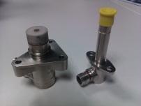
3 The probe 3 Q. Why do I need an optical probe? Q. Why can t I use a capacitance or eddy current sensor? This question is usually based upon the operational requirements, often it is not possible to get to the probe for maintenance and non-optical sensors have higher reliability and lifetimes in most applications. At RR we use exclusively optical sensors for development work. Q. Why? In the next slide we will discuss the probe resolution and relate it to the physical measurement. The probe resolution on its own does not define the need to end system resolution.
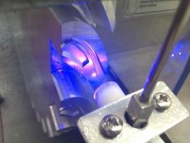
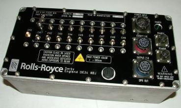
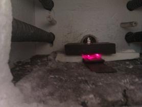
4 Optical probe typical performance 4 If we assume that we take a simple trigger point at 70% of the amplitude and the trigger uncertainty is ±10% (typically much better) then we can estimate the positional uncertainty as 0.1mm. This changes to 0.2mm as the probe to blade clearance changes from 1mm to 3mm. Typical noise at the timing generator is 40mV. (max output 5V) Laser power is either closed loop based upon probe amplitude or constant power maximum 80mW at 655nm. (visible for H&S reasons) For high temperature applications 80mW at 405nm. Optical receiver bandwidth is 3.5MHz.
5 Capacitance probe typical performance 5 Trigger points for slow rise time waveforms require more complexity. Typically the uncertainty is driven by signal noise. It is possible to achieve a similar resolution of 0.1 to 0.2mm as seen in the optical system. Typical noise at the timing generator is 60mV. (max output and Conditioning bandwidth is 150KHz. Probe sense diameter is 7.5mm

6 Optical v s Capacitance 6 Q. So which is best? To answer this we need to consider a few points. Blade vibration can be characterised by the shape, amplitude and frequency of the defection at the tip. The measurement point can be difficult to define for BTT. 120 m pk-pk 195 m pk-pk For a change in axial position of 0.3mm we get approximate 40% change in response amplitude. Note that the deflection at each point may have a different phase 300 m

7 Field of View 7 Optical sensor field of view Capacitance sensor field of view. A. If you can relate the time of arrival from the probe to blade behaviour then there is no problem. you can use capacitance or optical. Typically Large blade low deflection gradient either technology Small blade high deflection gradient - optical

8 Probe radial position 8 Q. What are the probe radial positions? A. Probes are positioned to best satisfy the mathematical requirements for the BTT algorithms. Most of which use a matrix to solve for amplitude. The matrix is designed to best solve for a particular engine order Probe positioned are designed to best satisfy many engine orders They may also be acting simultaneously The condition number is a mathematical property of the matrix and is the ratio of the maximum to minimum singular values for the matrix for each of the engine order models. There are many probe positions that can satisfy a set of requirements. A theoretical uncertainty value is associated with the value calculated based upon the BTT data processing
9 Condition number 9 Q. How do I calculate condition number? The following illustration shows how condition number can be calculated for a simple sinusoid For a square real, matrix, the square roots of the eigenvalues of A T A where A T is the transpose, are called singular values. Substitute = , = 0.209, = and EO = 3 Calculate the eigenvalues of A T A to be 4.734, and 1.25 The singular values are the square root of the eigenvalues 2.175, and 1.118
10 Condition number 10 Q. And what does it really mean? A large condition number (greater than ten??) means that the solution to the equation is sensitive to small changes (i.e. noise in the measurement) and may tend to give numerical problems when calculating a solution. A first approximation shows the range of errors have been created for a number of simulation files to illustrate this.

11 Condition number 11 Q. Is condition number the best way to define probe position Currently it s the most used method although as the number of probes increases it effect on the final result uncertainty is reduced.

 If the stress gradient at the between the dashed lines at the measurement point is high then we need to add further compensation to the measured")
12 Probe axial position 12 Q. I understand radial position but what about the axial position on a blade. In order to interpret the blade deflections it is necessary to know the sense position on a blade. Initial methods for achieving this were by static measurement and predictions of relative movements. (depicted by the dashed lines) If the stress gradient at the between the dashed lines at the measurement point is high then we need to add further compensation to the measured displacement value. At Rolls-Royce we use additional probes to allow us to extract the change in axial position during the test. typically we can resolve axial shifts of 0.1mm (these may be caused by lean, untwist or axial position change)

13 Mode Shape 13 Q. My blade modes are close in frequency and may cross how do I identify them? A. This can be achieved by using both leading and trailing edge probes. This type of configuration also allows axial shifts to be determined. This gives confidence that the LE and TE derived displacement's have some correlation. We can obtain the blade shape at speed to compare with our blade FEM Note the ratio change for when the response ND changes. As with any BTT interpretation you need a validated FEM
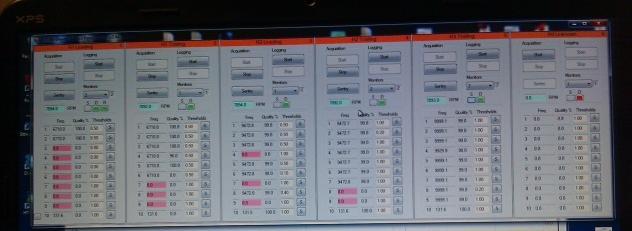
14 Frequency Results 14 Q. The blade would have failed within seconds if the amplitudes reported by BTT were true what s happening? A. Most BTT systems report peak amplitudes over a give analysis range. In order to create more realistic values rules can be defined to filter out obvious noise spikes. These are usually based upon continuous coherence against the model for a number of revolutions. In order to give a better perspective on response amplitude then we can also report the distribution of amplitude Histogram of Blade 02 (LE mm) Normal Mean StDev N 806 Max amplitude = mm. By plotting the number of occurrences of amplitude 60 alongside the maximum value a better understanding of the response can be gained Blade 02 (LE mm)
15 Resolution 15 Q. Do I really need 10µm resolution? Q. Can you actually achieve 10µm resolution? Depends on the application. Here we show the results for a mid stage HP compressor blade. Here the analysed displacement resolution is approximately 50µm which represents around 2% blade endurance. Currently acquisition to analysis BTT resolutions at Rolls-Royce for a large civil engine (1.3m diameter) are around 25µm Its very easy to get analysis paralysis checking things that don t really matter just takes time, effort and money!
16 Frequency range 16 Q. What is the highest frequency you can measure? A. Don t know. This is probably the most difficult to answer with any certainty. BTT measures displacement. If there is displacement at a high frequency that is above the resolution of the system then BTT data sets will contain it However, For higher frequencies that are often short lived it may be difficult to find it in the data set, So employ an expert to dig it out for you!!
17 Component certification 17 Q. Can I use BTT alone to certify my component? A. We would never use a single measurement system alone to certify components, and never have. BTT is a tool that can be used alongside modelling, fatigue testing, and many other standard techniques to gather sufficient certification evidence. Each company must make its own defence of techniques used to the certification authorities.

18 BTT analysis tools 18 Q. What analysis tools are available and do I have to be an expert to use them? A. Analysis now takes it most of our time in a BTT experiment We no longer regard the conversion of TOA data to displacements and frequency as the hard part. Interpretation is where most effort is now put. The skill of conversion resides in the software suite and, at RR, has to be automated to cope with the volume of data now being generated. The output of the BTT system is displacement data in a format that is compatible with interpretation tools. A standard file format for data interpretation tools would allow the use of third-party software. ISA107.1 please note!!


19 BTT analysis tools 19 Q. What standard input/output formats are there? A. We have a mixture of formats. Where we read data from our FEM analysis we are tied to a proprietary format however we have produced Excel tools that can mimic this for other users. The majority of our output files are created as.csv and can be viewed in Excel or Minitab. Data from all of internal processing steps are available to encourage thirdparty development of algorithms and methods. these formats are released to registered Users of Rolls-Royce analysis software. These contain similar data to the.ind format but may also include some additional pre processing of the data such as zeroing and filtering


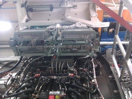
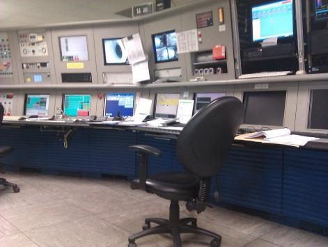
20 BTT weakest link 20 Q. What the hardest part of a BTT test? A. This differs for each industry sector but for Rolls-Royce it tends to be the application of significant numbers of probes to a vehicle. There are numerous failure points during engine build. Repeat running may be necessary to capture the required data once the engine leaves the test bed there is no way to collect more data. At RR the OPR systems are notoriously unreliable. There are methods available both internally and in the supply chain to remove the need for the OPR which are currently being validated.
21 Additional data 21 Q. I don t have access to blade endurance data or mode-shapes can I still use BTT? A. We have provided assistance to a number of third party s who are trying to use BTT for the first time. Where no blade endurance data is available then BTT may be no better than a random number generator. You can measure displacements and frequencies but have no way to interpret it. An increase in blade displacement is not always a bad thing. You can trend data over time and relate it to performance or efficiency. As with many other measurements you need supporting information to use the BTT data effectively. BTT is a measurement technology and not just a measurement system.
 Not only do you need hardware but also an understanding of what you are doing and a knowledge of how to apply it and the resulting data Q.")
22 I want one I think! 22 Q. What do I get when I buy a BTT system? A. A small part of a very complicated measurement process. (sometimes its just a big box of bits) Not only do you need hardware but also an understanding of what you are doing and a knowledge of how to apply it and the resulting data Q. So should I buy a turn-key system? Manuals not included A. If you are new to BTT then we would recommend that you employ experts in the beginning. If you wish to develop your own capability then ensure that you capture any knowledge from third party support.
23 Vendors 23 Q. I am a vendor, How do I get you to buy my products? A. In the past we have had great difficulties in using off-the shelf parts for our BTT system. Even today, although commercially sourced most of the design are based upon our own designs. We do allow access to our hardware interfaces to allow third-party designs to be integrated. Currently we are looking for new lasers systems, probe maintenance tools, IEEE1588 Ethernet compliant acquisition equipment. This is changing and we hope ISA107.1 will move this forward more quickly. Already from this group we have identified companies to work with to further our capabilities. We would like to leverage our $$$/ by working towards common goals. We will continue to publicise what we do and we would expect vendors to bring validated products to our door. We will invest R&D funding where standards do not exist and there is a clear capability improvement for us.
24 Vendors 24 Q. So what sort of products are you looking for? A. At Rolls-Royce we operate our systems in as a repeater technology. i.e. we cannot afford to have experts allocated to individual tests. Probes. Ruggedised lasers. Acquisition system. System operators for test support. Open source interfaces. Analysis algorithms. Installation design. Blade calibration services. Analysis off-load. Maintenance tools We want to buy standards parts but not at a premium cost!!


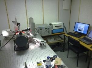
25 Vendors 25 Q. What facilities can you provide to vendors to assist in developing products? A. We have a number of spin test and environmental test rigs, however we need vendors to meet an initial set of requirements before we commit our resources System pass off rigs High temperature spinning rig Calibration facilities

26 BTT system development facilities 26 Probe resolution rig System pass-off rig Derby BTT supplier capability. Blade vibration lab University of Manchester.


27 We buy all of this in reasonable quantities 27 Application Acquisition Development Where do you fit in?? Training Operation Common Tools and Techniques shared across a wide range of people and functions
Research & Technology Overview
 Research & Technology Overview David Priestley Rolls-Royce International Ltd. November 2013 Global Education Dialogue - HCMC 2013 Rolls-Royce plc The information in this document is the property of Rolls-Royce
GT THE USE OF EDDY CURRENT SENSORS FOR THE MEASUREMENT OF ROTOR BLADE TIP TIMING: DEVELOPMENT OF A NEW METHOD BASED ON INTEGRATION
 Proceedings of ASME Turbo Expo 2016 GT2016 June 13-17, 2016, Seoul, South Korea GT2016-57368 THE USE OF EDDY CURRENT SENSORS FOR THE MEASUREMENT OF ROTOR BLADE TIP TIMING: DEVELOPMENT OF A NEW METHOD BASED
SABRe Briefs & Guidance
 SABRe Briefs & Guidance 2014 Rolls-Royce plc The information in this document is the property of Rolls-Royce plc and may not be copied or communicated to a third party, or used for any purpose other than
UNIVERS Telemetry System
 UNIVERS Telemetry System...making information work for you Full service support offered... In addition to the standard telemetry modules for direct usage with thermocouples, strain gauges and measuring
SMART LASER SENSORS SIMPLIFY TIRE AND RUBBER INSPECTION
 PRESENTED AT ITEC 2004 SMART LASER SENSORS SIMPLIFY TIRE AND RUBBER INSPECTION Dr. Walt Pastorius LMI Technologies 2835 Kew Dr. Windsor, ON N8T 3B7 Tel (519) 945 6373 x 110 Cell (519) 981 0238 Fax (519)
University of Huddersfield Repository
 University of Huddersfield Repository Allport, John and Jupp, Martyn Turbocharger blade vibration: Measurement and validation through laser tip timing Original Citation Allport, John and Jupp, Martyn (2012)
INDIAN INSTITUTE OF TECHNOLOGY BOMBAY
 IIT Bombay requests quotations for a high frequency conducting-atomic Force Microscope (c-afm) instrument to be set up as a Central Facility for a wide range of experimental requirements. The instrument
Developments in Electromagnetic Inspection Methods I
 6th International Conference on NDE in Relation to Structural Integrity for Nuclear and Pressurized Components October 2007, Budapest, Hungary For more papers of this publication click: www.ndt.net/search/docs.php3?mainsource=70
AGN 008 Vibration DESCRIPTION. Cummins Generator Technologies manufacture ac generators (alternators) to ensure compliance with BS 5000, Part 3.
 to ensure compliance with BS 5000, Part 3.") Application Guidance Notes: Technical Information from Cummins Generator Technologies AGN 008 Vibration DESCRIPTION Cummins Generator Technologies manufacture ac generators (alternators) to ensure compliance
Application Guidance Notes: Technical Information from Cummins Generator Technologies AGN 008 Vibration DESCRIPTION Cummins Generator Technologies manufacture ac generators (alternators) to ensure compliance
A Prototype Wire Position Monitoring System
 LCLS-TN-05-27 A Prototype Wire Position Monitoring System Wei Wang and Zachary Wolf Metrology Department, SLAC 1. INTRODUCTION ¹ The Wire Position Monitoring System (WPM) will track changes in the transverse
WIRELESS ASSET MONITORING
 WIRELESS ASSET MONITORING WITH ANALYSIS AND DATABASE TRANSLATOR SOFTWARE WAM 661 WAM 761 WAM 32U (pending) Rev. 5/10 WAM WIRELESS ASSET MONITORING SYSTEM OVERVIEW: Spectrum Instruments Ltd s WAM product
MONTRANO. Continuous monitoring system for power transformers
 MONTRANO Continuous monitoring system for power transformers Condition monitoring to extend transformer life Knowing the dielectric condition of insulation is vital Dielectric flashover of insulation in
red-ant measurement technologies and services Taunusstraße 51, Munich Tel. (+49) 089 /
 089 /") red-ant is a Munich-based team of dedicated specialists in NVH measurement engineering. For over 80 satisfied customers worldwide, red-ant sets new standards with high-precision measurement systems in
red-ant is a Munich-based team of dedicated specialists in NVH measurement engineering. For over 80 satisfied customers worldwide, red-ant sets new standards with high-precision measurement systems in
Vibration based condition monitoring of rotating machinery
 Vibration based condition monitoring of rotating machinery Goutam Senapaty 1* and Sathish Rao U. 1 1 Department of Mechanical and Manufacturing Engineering, Manipal Institute of Technology, Manipal Academy
Microwave Measurements from Benchtop Test Rig
 Microwave Measurements from Benchtop Test Rig Standards Michael Platt John Jagodnik Jeremy Weiss Certification Education & Training Publishing Conferences & Exhibits Presenter Michael Platt Currently a
In-Situ Damage Detection of Composites Structures using Lamb Wave Methods
 In-Situ Damage Detection of Composites Structures using Lamb Wave Methods Seth S. Kessler S. Mark Spearing Mauro J. Atalla Technology Laboratory for Advanced Composites Department of Aeronautics and Astronautics
PXIe Contents. Required Software CALIBRATION PROCEDURE
 CALIBRATION PROCEDURE PXIe-5113 This document contains the verification and adjustment procedures for the PXIe-5113. Refer to ni.com/calibration for more information about calibration solutions. Contents
DiMod 307 and SAE J211-1 Compliance. Dipl.-Ing. (FH) Jochen Schulz, Service Engineer, Kistler Automotive GmbH, Heidelberg, Germany
 Jochen Schulz, Service Engineer, Kistler Automotive GmbH, Heidelberg, Germany") DiMod 307 and SAE J211-1 Compliance Dipl.-Ing. (FH) Jochen Schulz, Service Engineer, Kistler Automotive GmbH, 69126 Heidelberg, Germany Contents 1 Performance Requirements for a Data Channel...3 2 Linearity
DiMod 307 and SAE J211-1 Compliance Dipl.-Ing. (FH) Jochen Schulz, Service Engineer, Kistler Automotive GmbH, 69126 Heidelberg, Germany Contents 1 Performance Requirements for a Data Channel...3 2 Linearity
Target Temperature Effect on Eddy-Current Displacement Sensing
 Target Temperature Effect on Eddy-Current Displacement Sensing Darko Vyroubal Karlovac University of Applied Sciences Karlovac, Croatia, darko.vyroubal@vuka.hr Igor Lacković Faculty of Electrical Engineering
MULTI-PARAMETER ANALYSIS IN EDDY CURRENT INSPECTION OF
 MULTI-PARAMETER ANALYSIS IN EDDY CURRENT INSPECTION OF AIRCRAFT ENGINE COMPONENTS A. Fahr and C.E. Chapman Structures and Materials Laboratory Institute for Aerospace Research National Research Council
Oscilloscope Measurement Fundamentals: Vertical-Axis Measurements (Part 1 of 3)
") Oscilloscope Measurement Fundamentals: Vertical-Axis Measurements (Part 1 of 3) This article is the first installment of a three part series in which we will examine oscilloscope measurements such as the
Oscilloscope Measurement Fundamentals: Vertical-Axis Measurements (Part 1 of 3) This article is the first installment of a three part series in which we will examine oscilloscope measurements such as the
D.C. Emmony, M.W. Godfrey and R.G. White
 A MINIATURE OPTICAL ACOUSTIC EMISSION TRANSDUCER ABSTRACT D.C. Emmony, M.W. Godfrey and R.G. White Department of Physics Loughborough University of Technology Loughborough, Leicestershire LEll 3TU United
Step Response of RC Circuits
 EE 233 Laboratory-1 Step Response of RC Circuits 1 Objectives Measure the internal resistance of a signal source (eg an arbitrary waveform generator) Measure the output waveform of simple RC circuits excited
Effective Industry-Academic Title - Arial 28pt
 Effective Industry-Academic Title - Arial 28pt Collaboration Dr Henner Wapenhans Head of Technology Strategy HEPI Autumn Conference, 5. December 2012, The Royal Society, London 2012 Rolls-Royce plc The
XM: The AOI camera technology of the future
 No. 29 05/2013 Viscom Extremely fast and with the highest inspection depth XM: The AOI camera technology of the future The demands on systems for the automatic optical inspection (AOI) of soldered electronic
Enhancing the capability of primary calibration system for shock acceleration in NML
 Enhancing the capability of primary calibration system for shock acceleration in NML Jiun-Kai CHEN 1 ; Yen-Jong HUANG 1 1 Center for Measurement Standards, Industrial Technology Research Institute, R.O.C.
PeakVue Analysis for Antifriction Bearing Fault Detection
 Machinery Health PeakVue Analysis for Antifriction Bearing Fault Detection Peak values (PeakVue) are observed over sequential discrete time intervals, captured, and analyzed. The analyses are the (a) peak
Capabilities of Flip Chip Defects Inspection Method by Using Laser Techniques
 Capabilities of Flip Chip Defects Inspection Method by Using Laser Techniques Sheng Liu and I. Charles Ume* School of Mechanical Engineering Georgia Institute of Technology Atlanta, Georgia 3332 (44) 894-7411(P)
Why Modern Servicing Requires Complete Waveform & Circuit Analyzing!
 Why Modern Servicing Requires Complete Waveform & Circuit Analyzing! DC Bias Voltages DC Currents Resistance AC Signals Of Various Waveshapes & Amplitudes Continuity Of Circuit Paths & Components If you
Maximizing the Fatigue Crack Response in Surface Eddy Current Inspections of Aircraft Structures
 Maximizing the Fatigue Crack Response in Surface Eddy Current Inspections of Aircraft Structures Catalin Mandache *1, Theodoros Theodoulidis 2 1 Structures, Materials and Manufacturing Laboratory, National
Transient calibration of electric field sensors
 Transient calibration of electric field sensors M D Judd University of Strathclyde Glasgow, UK Abstract An electric field sensor calibration system that operates in the time-domain is described and its
Vibration Fundamentals Training System
 Vibration Fundamentals Training System Hands-On Turnkey System for Teaching Vibration Fundamentals An Ideal Tool for Optimizing Your Vibration Class Curriculum The Vibration Fundamentals Training System
7 Hints That Every Engineer Should Know When Making Power Measurements with Oscilloscopes.
 7 Hints That Every Engineer Should Know When Making Power Measurements with Oscilloscopes. Achieving maximized measurement dynamic range 1) Use averaging to increase measurement resolution 2) Use high-resolution
Peter Dack, Vice President Sales & Marketing Radian Research, Inc.
 Peter Dack, Vice President Sales & Marketing pdack@radianresearch.com Radian Research, Inc. Radian Research, Inc. is a world leader in State of the Art energy measurement instrumentation. Radian designs,
Predictive Maintenance with Multi-Channel Analysis in Route and Analyze Mode
 Machinery Health Management Predictive Maintenance with Multi-Channel Analysis in Route and Analyze Mode Presented at EuroMaintenance 2014, Helsinki, Finland, by Johan Van Puyenbroeck. Traditional route-based
Characterizing High-Speed Oscilloscope Distortion A comparison of Agilent and Tektronix high-speed, real-time oscilloscopes
 Characterizing High-Speed Oscilloscope Distortion A comparison of Agilent and Tektronix high-speed, real-time oscilloscopes Application Note 1493 Table of Contents Introduction........................
Final Year Projects 2016/7 Integrated Photonics Group
 Final Year Projects 2016/7 Integrated Photonics Group Overview: This year, a number of projects have been created where the student will work with researchers in the Integrated Photonics Group. The projects
First and second order systems. Part 1: First order systems: RC low pass filter and Thermopile. Goals: Department of Physics
 slide 1 Part 1: First order systems: RC low pass filter and Thermopile Goals: Understand the behavior and how to characterize first order measurement systems Learn how to operate: function generator, oscilloscope,
Aerospace Software* Cost and Timescale Reduction *and complex electronic hardware
 Aerospace Software* Cost and Timescale Reduction *and complex electronic hardware Andrew Hawthorn Deputy Director, Intelligent Systems / Altran UK and SECT-AIR WP4 Lead on behalf of the SECT-AIR Consortium
Techniques for blade tip clearance measurements with capacitive probes
 Meas. Sci. Technol. 11 (2000) 865 869. Printed in the UK PII: S0957-0233(00)09607-7 Techniques for blade tip clearance measurements with capacitive probes Alexander Steiner Hytron GmbH, Georg Schröbel
Traceability and Modulated-Signal Measurements
 Traceability and Modulated-Signal Measurements Kate A. Remley 1, Dylan F. Williams 1, Paul D. Hale 2 and Dominique Schreurs 3 1. NIST Electromagnetics Division 2. NIST Optoelectronics Division 3. K.U.
Considerations: Evaluating Three Identification Technologies
 Considerations: Evaluating Three Identification Technologies A variety of automatic identification and data collection (AIDC) trends have emerged in recent years. While manufacturers have relied upon one-dimensional
Determining the Fatigue Life of Aero-Engine Blades
 w w w. s c i t e k c o n s u l t a n t s. c o. u k Determining the Fatigue Life of Aero-Engine Blades SCITEK Consultants Ltd Martin Haste, Florian Faurillou, Jon Bates, Marios S Christodoulou 4 th November
USE OF BASIC ELECTRONIC MEASURING INSTRUMENTS Part II, & ANALYSIS OF MEASUREMENT ERROR 1
 EE 241 Experiment #3: USE OF BASIC ELECTRONIC MEASURING INSTRUMENTS Part II, & ANALYSIS OF MEASUREMENT ERROR 1 PURPOSE: To become familiar with additional the instruments in the laboratory. To become aware
EET 273 Experiment Introduction to Loop Control
 Now that we have calibrated and characterized all of the pieces of our system, we are ready to begin to attempt to accurately control the motor. Our system is designed to control the speed of the motor.
Predictive Diagnostics for Pump Seals: Field Trial Learnings. Matthew Miller, John Crane
 Predictive Diagnostics for Pump Seals: Field Trial Learnings Matthew Miller, John Crane Brad D. Lewis Senior Reliability Engineer Authors Bios Matthew Miller Field Service Engineer At INEOS from 2014-2016
Inspection of composite structures Dr Roger M. Groves Aerospace Non-Destructive Testing Laboratory November 26, 2014
 Inspection of composite structures Dr Roger M. Groves Aerospace Non-Destructive Testing Laboratory November 26, 2014 1 Faculty of Aerospace Engineering Abstract Introduction of the latest developments
UNIT-4 POWER QUALITY MONITORING
 UNIT-4 POWER QUALITY MONITORING Terms and Definitions Spectrum analyzer Swept heterodyne technique FFT (or) digital technique tracking generator harmonic analyzer An instrument used for the analysis and
Co-Located Triangulation for Damage Position
 Co-Located Triangulation for Damage Position Identification from a Single SHM Node Seth S. Kessler, Ph.D. President, Metis Design Corporation Ajay Raghavan, Ph.D. Lead Algorithm Engineer, Metis Design
Applications Note. Bently Nevada* Asset Condition Monitoring. Periodically Monitored Assets. Connecting SCOUT to Continuous Monitoring Systems
 Bently Nevada* Asset Condition Monitoring Connecting SCOUT to Continuous Monitoring Systems The most effective installations of continuous monitoring instruments such as the 3500 system include integration
LION. TechNote LT September, 2014 PRECISION. Understanding Sensor Resolution Specifications and Performance
 LION PRECISION TechNote LT05-0010 September, 2014 Understanding Sensor Resolution Specifications and Performance Applicable Equipment: All noncontact displacement sensors Applications: All noncontact displacement
Bearing Fault Diagnosis
 Quick facts Bearing Fault Diagnosis Rolling element bearings keep our machines turning - or at least that is what we expect them to do - the sad reality however is that only 10% of rolling element bearings
Laser Technology Improves and Makes Easier Post-Process Measuring On Centreless Grinders. Application Note. A. Spizzamiglio - Aeroel - Italy SUMMARY:
 Application Note Laser Technology Improves and Makes Easier Post-Process Measuring On Centreless Grinders. SUMMARY: Introduction Laser Technology sets new performance standards Application for centreless
15 th Asia Pacific Conference for Non-Destructive Testing (APCNDT2017), Singapore.
, Singapore.") Time of flight computation with sub-sample accuracy using digital signal processing techniques in Ultrasound NDT Nimmy Mathew, Byju Chambalon and Subodh Prasanna Sudhakaran More info about this article:
Time of flight computation with sub-sample accuracy using digital signal processing techniques in Ultrasound NDT Nimmy Mathew, Byju Chambalon and Subodh Prasanna Sudhakaran More info about this article:
Introduction to Measurement Systems
 MFE 3004 Mechatronics I Measurement Systems Dr Conrad Pace Page 4.1 Introduction to Measurement Systems Role of Measurement Systems Detection receive an external stimulus (ex. Displacement) Selection measurement
LFR: flexible, clip-around current probe for use in power measurements
 LFR: flexible, clip-around current probe for use in power measurements These technical notes should be read in conjunction with the LFR short-form datasheet. Power Electronic Measurements Ltd Nottingham
Terms and expressions for specifying torque transducers
 Terms and expressions for specifying torque transducers Terms and expressions for specifying torque transducers Metrological properties of the torque measuring system Accuracy class The accuracy class
Keysight Technologies Make Better AC RMS Measurements with Your Digital Multimeter. Application Note
 Keysight Technologies Make Better AC RMS Measurements with Your Digital Multimeter Application Note Introduction If you use a digital multimeter (DMM) for AC voltage measurements, it is important to know
of harmonic cancellation algorithms The internal model principle enable precision motion control Dynamic control
 Dynamic control Harmonic cancellation algorithms enable precision motion control The internal model principle is a 30-years-young idea that serves as the basis for a myriad of modern motion control approaches.
Precision power measurements for megawatt heating controls
 ARTICLE Precision power measurements for megawatt heating controls Lars Alsdorf (right) explains Jürgen Hillebrand (Yokogawa) the test of the power controller. Precision power measurements carried out
Chapter 1: DC circuit basics
 Chapter 1: DC circuit basics Overview Electrical circuit design depends first and foremost on understanding the basic quantities used for describing electricity: voltage, current, and power. In the simplest
Acoustic Resonance Analysis Using FEM and Laser Scanning For Defect Characterization in In-Process NDT
 ECNDT 2006 - We.4.8.1 Acoustic Resonance Analysis Using FEM and Laser Scanning For Defect Characterization in In-Process NDT Ingolf HERTLIN, RTE Akustik + Prüftechnik, Pfinztal, Germany Abstract. This
Also, side banding at felt speed with high resolution data acquisition was verified.
 PEAKVUE SUMMARY PeakVue (also known as peak value) can be used to detect short duration higher frequency waves stress waves, which are created when metal is impacted or relieved of residual stress through
Rotating Coil Measurement Errors*
 Rotating Coil Measurement Errors* Animesh Jain Superconducting Magnet Division Brookhaven National Laboratory, Upton, NY 11973, USA 2 nd Workshop on Beam Dynamics Meets Magnets (BeMa2014) December 1-4,
Figure for the aim4np Report
 Figure for the aim4np Report This file contains the figures to which reference is made in the text submitted to SESAM. There is one page per figure. At the beginning of the document, there is the front-page
MATHEMATICAL MODEL VALIDATION
 CHAPTER 5: VALIDATION OF MATHEMATICAL MODEL 5-1 MATHEMATICAL MODEL VALIDATION 5.1 Preamble 5-2 5.2 Basic strut model validation 5-2 5.2.1 Passive characteristics 5-3 5.2.2 Workspace tests 5-3 5.3 SDOF
ECE 4670 Spring 2014 Lab 1 Linear System Characteristics
 ECE 4670 Spring 2014 Lab 1 Linear System Characteristics 1 Linear System Characteristics The first part of this experiment will serve as an introduction to the use of the spectrum analyzer in making absolute
Capacitive MEMS accelerometer for condition monitoring
 Capacitive MEMS accelerometer for condition monitoring Alessandra Di Pietro, Giuseppe Rotondo, Alessandro Faulisi. STMicroelectronics 1. Introduction Predictive maintenance (PdM) is a key component of
University of Molise Engineering Faculty Dept. SAVA Engineering & Environment Section. C. Rainieri, G. Fabbrocino
 University of Molise Engineering Faculty Dept. SAVA Engineering & Environment Section C. Rainieri, G. Fabbrocino Operational Modal Analysis: overview and applications Carlo Rainieri Strucutural and Geotechnical
Straightness & Parallelism
 125 years of innovation Straightness & Parallelism 1 Contents Straightness Measurement Reference Types Analysis Filter Selection Gaussian Filter Characteristics Straightness on Narrow Components Parallelism
rotary encoder system
 L-9517-9466-01-B TONiC DSi dual readhead rotary encoder system DSi brings higher accuracy to rotary axes whilst propoz technology offers a selectable reference mark position. Using two readheads on an
SUPPLEMENTARY INFORMATION
 Figure S. Experimental set-up www.nature.com/nature Figure S2. Dependence of ESR frequencies (GHz) on a magnetic field (G) applied in different directions with respect to NV axis ( θ 2π). The angle with
A Comparison of Performance Characteristics of On and Off Axis High Resolution Hall Effect Encoder ICs
 A Comparison of Performance Characteristics of On and Off Axis High Resolution Hall Effect Encoder ICs Sensor Products Mark LaCroix A John Santos Dr. Lei Wang 8 FEB 13 Orlando Originally Presented at the
Make Better AC RMS Measurements with your Digital Multimeter APPLICATION NOTE
 Make Better AC RMS Measurements with your Digital Multimeter APPLICATION NOTE Introduction If you use a digital multimeter (DMM) for AC voltage measurements, it is important to know what type of reading
EXPERIMENT NUMBER 2 BASIC OSCILLOSCOPE OPERATIONS
 1 EXPERIMENT NUMBER 2 BASIC OSCILLOSCOPE OPERATIONS The oscilloscope is the most versatile and most important tool in this lab and is probably the best tool an electrical engineer uses. This outline guides
Evaluation of Steady-State and Dynamic Performance of a Synchronized Phasor Measurement Unit
 Electrical Power and Energy Conference 2012 Resilient Green Energy Systems for a Sustainable Society Evaluation of Steady-State and Dynamic Performance of a Synchronized Phasor Measurement Unit Dinesh
The Fastest, Easiest, Most Accurate Way To Compare Parts To Their CAD Data
 210 Brunswick Pointe-Claire (Quebec) Canada H9R 1A6 Web: www.visionxinc.com Email: info@visionxinc.com tel: (514) 694-9290 fax: (514) 694-9488 VISIONx INC. The Fastest, Easiest, Most Accurate Way To Compare
Riser Lifecycle Monitoring System for Integrity Management
 Riser Lifecycle Monitoring System for Integrity Management 11121-5402-01 Judith Guzzo GE Global Research RPSEA Ultra-Deepwater Technology Conference October 29-30, 2013 Lone Star College Conference Center
Electron Spin Resonance v2.0
 Electron Spin Resonance v2.0 Background. This experiment measures the dimensionless g-factor (g s ) of an unpaired electron using the technique of Electron Spin Resonance, also known as Electron Paramagnetic
MEMS On-wafer Evaluation in Mass Production Testing At the Earliest Stage is the Key to Lowering Costs
 MEMS On-wafer Evaluation in Mass Production Testing At the Earliest Stage is the Key to Lowering Costs Application Note Recently, various devices using MEMS technology such as pressure sensors, accelerometers,
Inspector Data Sheet. EM-FI Transient Probe. High speed pulsed EM fault injection probe for localized glitches. Riscure EM-FI Transient Probe 1/8
 Inspector Data Sheet EM-FI Transient Probe High speed pulsed EM fault injection probe for localized glitches. Riscure EM-FI Transient Probe 1/8 Introduction With increasingly challenging chip packages
Technology Readiness Level assessment and Capability Route Mapping for Special Engineered Structures for a Far Infrared Space Telescope
 1 Technology Readiness Level assessment and Capability Route Mapping for Special Engineered Structures for a Far Infrared Space Telescope Alison J. McMillan Glyndwr University 15-17 December 2015 FISICA
IMPORTANCE OF ACCURATE MEASUREMENTS DURING THE LIFE CYCLE OF UTILITIES
 IMPORTANCE OF ACCURATE MEASUREMENTS DURING THE LIFE CYCLE OF UTILITIES Thomas Steiner HIGHVOLT Prüftechnik Dresden GmbH Lifecycle of utilities time schedule utilities Tests during life cycle of utilities
Appendix A: Specifications
 All specifications apply to the TDS 200-Series Digital Oscilloscopes and a P2100 probe with the Attenuation switch set to 10X unless noted otherwise. To meet specifications, two conditions must first be
IEEE 802.3ba 40Gb/s and 100Gb/s Ethernet Task Force 22th Sep 2009
 Draft Amendment to IEEE Std 0.-0 IEEE Draft P0.ba/D. IEEE 0.ba 0Gb/s and 00Gb/s Ethernet Task Force th Sep 0.. Stressed receiver sensitivity Stressed receiver sensitivity shall be within the limits given
TechNote. T001 // Precise non-contact displacement sensors. Introduction
 TechNote T001 // Precise non-contact displacement sensors Contents: Introduction Inductive sensors based on eddy currents Capacitive sensors Laser triangulation sensors Confocal sensors Comparison of all
A Time-Saving Method for Analyzing Signal Integrity in DDR Memory Buses
 A Time-Saving Method for Analyzing Signal Integrity in DDR Memory Buses Application Note 1591 This application note covers new tools and measurement techniques for characterizing and validating signal
Rohde & Schwarz EMI/EMC debugging with modern oscilloscope. Ing. Leonardo Nanetti Rohde&Schwarz
 Rohde & Schwarz EMI/EMC debugging with modern oscilloscope Ing. Leonardo Nanetti Rohde&Schwarz EMI debugging Agenda l The basics l l l l The idea of EMI debugging How is it done? Application example What
New Features of IEEE Std Digitizing Waveform Recorders
 New Features of IEEE Std 1057-2007 Digitizing Waveform Recorders William B. Boyer 1, Thomas E. Linnenbrink 2, Jerome Blair 3, 1 Chair, Subcommittee on Digital Waveform Recorders Sandia National Laboratories
AlphaProx inductive sensors. Measure distances accurate to a micrometer.
 AlphaProx inductive sensors Measure distances accurate to a micrometer. AlphaProx sensors simply offer more AlphaProx by Baumer is a flexible platform for inductive distance-measuring sensors, with fully
eddyncdt 3010 Non-Contact Displacement Measuring Systems
 Eddy current sensors for displacement, distance and position Eddy current and inductive measurement system and sensors with micrometer resolution for linear measurement and displacement, distance and position
Design of a Piezoelectric-based Structural Health Monitoring System for Damage Detection in Composite Materials
 Design of a Piezoelectric-based Structural Health Monitoring System for Damage Detection in Composite Materials Seth S. Kessler S. Mark Spearing Technology Laboratory for Advanced Composites Department
IT S A COMPLEX WORLD RADAR DEINTERLEAVING. Philip Wilson. Slipstream Engineering Design Ltd.
 IT S A COMPLEX WORLD RADAR DEINTERLEAVING Philip Wilson pwilson@slipstream-design.co.uk Abstract In this paper, we will look at how digital radar streams of pulse descriptor words are sorted by deinterleaving
M70LL Laser Distance Sensor
 M7LL Laser Distance Sensor for automated manufacturing with Ethernet interface to connect with PLC The analog sensors of series M7LL use a PSD for their receiver optics. This assures a position measurement
MAGNETOSCAN MAGNETIC MEASURING SCANNER
 LABORATORIO ELETTROFISICO MAGNETOSCAN MAGNETIC MEASURING SCANNER Fully automated ease with micrometrical accuracy A magnetic measuring scanner, the Magnetoscan is designed to measure the superficial magnetic
It s Our Business to be EXACT
 671 LASER WAVELENGTH METER It s Our Business to be EXACT For laser applications such as high-resolution laser spectroscopy, photo-chemistry, cooling/trapping, and optical remote sensing, wavelength information
Chapter 5. Signal Analysis. 5.1 Denoising fiber optic sensor signal
 Chapter 5 Signal Analysis 5.1 Denoising fiber optic sensor signal We first perform wavelet-based denoising on fiber optic sensor signals. Examine the fiber optic signal data (see Appendix B). Across all
Water Meter Basics Incremental encoders
 Water Meter Basics Measuring flow can be accomplished in a number of ways. For residential applications, the two most common approaches are turbine and positive displacement technologies. The turbine meters
ON-LINE PARTIAL DISCHARGE TESTING OF SOME OF THE WORST PERFORMING CIRCUITS ON A UTILITY DISTRIBUTION SYSTEM
 ON-LINE PARTIAL DISCHARGE TESTING OF SOME OF THE WORST PERFORMING CIRCUITS ON A UTILITY DISTRIBUTION SYSTEM D. Clark¹ R. Mackinlay² M. Seltzer-Grant² S. Goodfellow² Lee Renforth² Jamie McWilliam³ and Roger
An observation on non-linear behaviour in condition monitoring
 การประช มเคร อข ายว ศวกรรมเคร องกลแห งประเทศไทยคร งท 18 18-20 ต ลาคม 2547 จ งหว ดขอนแก น An observation on non-linear behaviour in condition monitoring Apirak Jiewchaloemmit 1, Janewith Luangcharoenkij