Manual UT vs PIMS (Permanently installed monitoring sensors)
|
|
|
- Melinda Booker
- 5 years ago
- Views:
Transcription
 F. B.")

1 Manual UT vs PIMS (Permanently installed monitoring sensors) F. B. Cegla Non-Destructive Evaluation Group, Department of Mechanical Engineering Imperial College London, SW7 AZ,UK
2 Outline /36 Motivation/Background Corrosion example + Surface Roughness The effect of roughness on scattering Simulation method (DPSM) Results PIMS/ C-Scan Conclusions Future work

3 Actual Thickness (normalised) Motivation/Background 3/36 Corrosion costs several billion $/annum Inspection very important to avoid failures Main tool Manual UT Inspection After: van Roodselar et al., 9 Inspectors Summit 9, Galveston Texas Source: Measured Thickness (normalised)
 Permanently installed sensors (PIMS)")

4 Motivation/Background 4/36 Human factors are potential source of large spread Mechanized scanning Inspection (C-Scan) Permanently installed sensors (PIMS) Source: Source: What is the likely size of measurement errors? What is the likely influence of roughness on the ultrasonic signal?
5 Amplitude Ultrasonic thickness measurement principle 5/36 T 1 t t p p 1 Wall thickness (T) Transmitter.5.1 Pitch (p) Receiver Wave speed (v) t 1 Surface skimming wave.15. Not to scale t =? t Backwall.5 reflection.3 Time
6 What is the effect of roughness on UT 6/36 Ingredients considered: Length scales that have an effect on UT signal Typical surface roughness in the field Transducer geometry Fast simulation technique for statistics Signal processing techniques
7 Rough surface definition 7/36 Gaussian distributed: Uses normally distributed random numbers to generate different surfaces with similar statistics. Correlation length (λ ) RMS height (σ) Correlation length (λ ) RMS height (σ)
8 Scale of roughness that affects UT signal 8/36 Rayleigh parameter: transition to high surface RMS k cos 4 k = wavenumber σ = RMS height θ = incident and reflected angle RMS value ~.mm in steel for S waves (~.5 MHz) or P waves (~5 MHz) But what about horizontal extent? What horizontal scales must be present for scattering to influence the signal? J. A. Ogilvy. Theory of Wave Scattering from Random Rough Surfaces. IOP publishing Ltd. 1991

 8 6 4 8 1 6 4 1-1 -5 5 1 x-axis (mm)")
 -1-8 6 4 8 1 6 4 1-1 -5 5")

9 y-axis (mm) y-axis (mm) amplitude (arb) y-axis (mm) y-axis (mm) amplitude (arb) Scale of roughness that influences UT signal 9/36 1 λs=.5mm (.3λ) 1 λs=mm (1.λ) x-axis (mm) 1 λs=8mm (5λ) x-axis (mm) 1 λs=5mm (31λ) x-axis (mm) x-axis (mm) -1 -
10 y-axis (mm) amplitude (arb) Scale of roughness that influences UT Signal 1/36 D Problem, Tx, Rx (.6 width) MHz, 5 cycles, = 1.6mm: sinusoidal surface wavelength =.mm backwall transmitter receiver flat backwall sinusoidal backwall hilbert envelope x-axis (mm) time ( s) NOTE: trough in surface always occurs directly between transmitter and receiver
11 y-axis (mm) amplitude (arb) Scale of roughness that influences UT Signal 11/36 D Problem, Tx, Rx (.6 width) MHz, 5 cycles, = 1.6mm: sinusoidal surface wavelength =.4mm backwall transmitter receiver flat backwall sinusoidal backwall hilbert envelope x-axis (mm) time ( s) NOTE: trough in surface always occurs directly between transmitter and receiver
12 y-axis (mm) amplitude (arb) Scale of roughness that influences UT Signal 1/36 D Problem, Tx, Rx (.6 width) MHz, 5 cycles, = 1.6mm: sinusoidal surface wavelength = 4mm backwall transmitter receiver flat backwall sinusoidal backwall hilbert envelope x-axis (mm) time ( s) NOTE: trough in surface always occurs directly between transmitter and receiver
13 y-axis (mm) amplitude (arb) Scale of roughness that influences UT Signal 13/36 D Problem, Tx, Rx (.6 width) MHz, 5 cycles, = 1.6mm: sinusoidal surface wavelength = 4mm backwall transmitter receiver flat backwall sinusoidal backwall hilbert envelope x-axis (mm) time ( s) NOTE: trough in surface always occurs directly between transmitter and receiver
14 amplitude change (db) Scale of roughness that influences UT signal 14/36 Look at max. amplitude of backwall reflection as surface wavelength increases compared to max. amplitude of flat backwall reflection: sinusoidal surface wavelength ( s / )
15 Scale of roughness that influences UT signal 15/36 The simulations show: For rough surfaces with horizontal length scales (L) roughness distorts the signal if: o vertical RMS height > λ o horizontal FFT of surface contains.8 λ < L < 5-1 λ


16 Sulphidation corrosion example 16/36 o RMS height =.1-.5mm o FFT of surface contains scales of L between 1-1mm Picture from: Taylor-Hobson
17 Typical Transducer parameters 17/36 Parameter C-SCAN PIMS Transducer Area 6mm diameter 1x1mm rectangular Operational frequency Operational wavelength (steel) Beam footprint (at 1mm depth) 5 MHz MHz ~1 mm ~1.5mm ~6mm diameter ~8-1mm Corrosion RMS height =.1-.5mm ~.1-.3λ Corroded surface FFT scales = 1-1mm or.8λ < L < 1λ
18 Operation in region where roughness influences signal Statistical Simulations 18/36
19 DPSM: basic principle 19/36 Fundamentally based on Huygens principle Propagating wave front can be discretised into contributions from many point sources. Field at a single target point is then the summation of contributions from all point sources Propagating wave front Point Sources D: P m m () m r A H k r Target point n n f n Free Space Greens function 3D: P m m An m r exp ik r n r m n f n Placko, D. and Kundu, T. DPSM for Modeling Engineering Problems. (7)
20 DPSM: Matrix formulation /36 Equations cast into set of linear equations All contributions calculated in a single step P T N source points A 1 A A 3 r 1 m r m r 3 m r N m P 1 P P m P M Q TS A S Q TS exp ikf r 1 r exp f r1 exp f 1 M r1 1 1 exp ik r f 1 1 N ik r exp ik r exp ik r 1 f r M M M ik r exp ik r exp ik r r f M r 1 exp ik r r f 1 f N r f M N r 1 N N N M target points A N P Q T TS A S
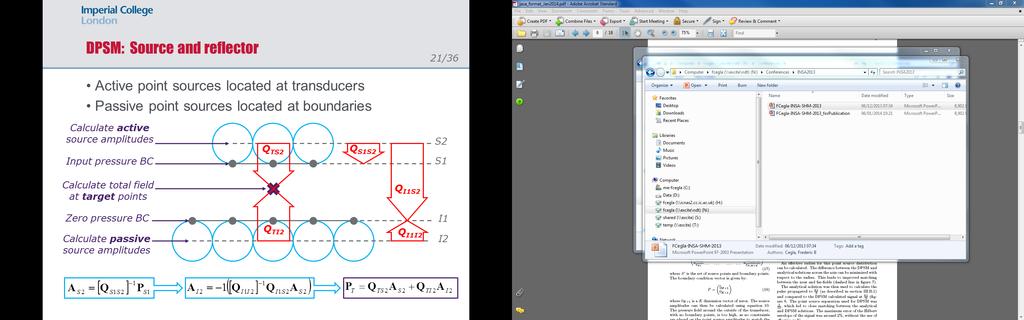
21 1/36
22 amplitude (arb) y-axis (mm) D simulation case study different models /36 Single acoustic wave transceiver point source (λ=1.6mm) σ = 3λ c /16 x-axis (mm) Backwall FEM DPSM Kirchoff time ( s) Method Nodes Time taken (s) FEM DPSM Kirchhoff Chosen for its very high speed and ability to simulate multiple scattering and shadowing

23 Permanently installed sensor simulations 3/36 Transducer field l f l f l f l f l f MHz SH wave.5x1mm contact Average surface z y x
24 Permanently installed sensor simulations 4/36 Transducer field MHz SH wave.5x1mm contact z y x Inner surface Footprint width
25 amplitude (arb) Extracting a thickness from the simulated signal 5/36 Wall Thickness Example Envelope peak algorithm is used to evaluate the range of wall thicknesses that would be measured from many surfaces with the same roughness/surface statistics. TOF Envelope Peak (EP) time ( s)
. : Jarvis, A.J.C and Cegla, F.B.")
26 Effect of roughness on thickness measurement? 6/36 1 surface realisations at each RMS for correlation length.8mm Peak to peak timing algorithm 1: Jarvis, A.J.C. and Cegla, F.B., Application of the Distributed Point Source Method to Rough Surface Scattering and Ultrasonic Wall Thickness Measurement, JASA (1). : Jarvis, A.J.C and Cegla, F.B., (13) Scattering of SH Waves by Sinusoidal and Rough Surfaces in 3D: Comparison to the Scalar Wave Approximation, manuscript in peer review process 13

27 C-scan transducer field 7/36 6mm 1mm 8mm 8mm
28 Mean of thickness estimates (mm) C-scan transducer results, 1 surfaces 8/36
29 Sampling due to the footprint 9/36 Transducer only probes a small area of the surface Transducer How much of this variation is due to this sampling effect? 9.8mm 1mm
30 Standard dev. of thickness estimates (mm) C-scan transducer results, 1 surfaces 3/36
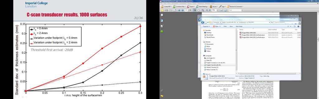
31 31/36
32 Conclusion 3/36 Vertical RMS >~1/1 incident wavelength UT signal can be distorted Horizontal CL~.8-1 incident wavelength UT signal can be distorted For simulations with RMS >1/1 UT measurement std > surface RMS spread due to interaction of signal processing with the scattered signal Awareness of this important: measurement spread and uncertainties not due to UT setup and equipment but due to structure property itself.
33 Actual Thickness (normalised) Conclusion 33/36 All UT measurements influenced by the physics: manual, automatic scanning and permanently installed After: van Roodselar et al., 9 Inspectors Summit 9, Galveston Texas Measured Thickness (normalised)
34 Future Work 34/36 Link more temporal and spatial information Link to underlying corrosion mechanisms (general vs pitting corrosion)

35 Acknowledgements 35/36 For contribution: Dr Andrew Jarvis Mr Attila Gajdacsi Mr Daniel Benstock Sponsors:
36 QUESTIONS 36/36 QUESTIONS?
MODELLING ULTRASONIC INSPECTION OF ROUGH DEFECTS. J.A. Ogilvy UKAEA, Theoretical Physics Division HARWELL Laboratory. Didcot, Oxon OXll ORA, U.K.
 MODELLING ULTRASONIC INSPECTION OF ROUGH DEFECTS J.A. Ogilvy UKAEA, Theoretical Physics Division HARWELL Laboratory Didcot, Oxon Oll ORA, U.K. INTRODUCTION Ultrasonic signals are affected by the nature
Propagation Mechanism
 Propagation Mechanism ELE 492 FUNDAMENTALS OF WIRELESS COMMUNICATIONS 1 Propagation Mechanism Simplest propagation channel is the free space: Tx free space Rx In a more realistic scenario, there may be
Small-Scale Fading I PROF. MICHAEL TSAI 2011/10/27
 Small-Scale Fading I PROF. MICHAEL TSAI 011/10/7 Multipath Propagation RX just sums up all Multi Path Component (MPC). Multipath Channel Impulse Response An example of the time-varying discrete-time impulse
Structural UT: Variables Affecting Attenuation and Review of the 2 db per Inch Model
 Structural UT: Variables Affecting Attenuation and Review of the 2 db per Inch Model Paul Holloway, P.Eng, MASc, CGSB UT3 MT2 President, Holloway NDT & Engineering Inc. Purpose & Practical Applications
An Overview Algorithm to Minimise Side Lobes for 2D Circular Phased Array
 An Overview Algorithm to Minimise Side Lobes for 2D Circular Phased Array S. Mondal London South Bank University; School of Engineering 103 Borough Road, London SE1 0AA More info about this article: http://www.ndt.net/?id=19093
ECE 476/ECE 501C/CS Wireless Communication Systems Winter Lecture 6: Fading
 ECE 476/ECE 501C/CS 513 - Wireless Communication Systems Winter 2005 Lecture 6: Fading Last lecture: Large scale propagation properties of wireless systems - slowly varying properties that depend primarily
ECE 476/ECE 501C/CS Wireless Communication Systems Winter Lecture 6: Fading
 ECE 476/ECE 501C/CS 513 - Wireless Communication Systems Winter 2004 Lecture 6: Fading Last lecture: Large scale propagation properties of wireless systems - slowly varying properties that depend primarily
A COMPARISON BETWEEN ASTM E588 AND SEP 1927 RELATING RESOLUTION LIMITS AT DETERMINATION OF THE PURITY GRADE
 19 th World Conference on Non-Destructive Testing 2016 A COMPARISON BETWEEN ASTM E588 AND SEP 1927 RELATING RESOLUTION LIMITS AT DETERMINATION OF THE PURITY GRADE Daniel KOTSCHATE 1, Dirk GOHLKE 1, Rainer
Channel Modelling ETIM10. Propagation mechanisms
 Channel Modelling ETIM10 Lecture no: 2 Propagation mechanisms Ghassan Dahman \ Fredrik Tufvesson Department of Electrical and Information Technology Lund University, Sweden 2012-01-20 Fredrik Tufvesson
Finite element simulation of photoacoustic fiber optic sensors for surface rust detection on a steel rod
 Finite element simulation of photoacoustic fiber optic sensors for surface rust detection on a steel rod Qixiang Tang a, Jones Owusu Twumasi a, Jie Hu a, Xingwei Wang b and Tzuyang Yu a a Department of
Mobile Radio Propagation Channel Models
 Wireless Information Transmission System Lab. Mobile Radio Propagation Channel Models Institute of Communications Engineering National Sun Yat-sen University Table of Contents Introduction Propagation
ECE 476/ECE 501C/CS Wireless Communication Systems Winter Lecture 6: Fading
 ECE 476/ECE 501C/CS 513 - Wireless Communication Systems Winter 2003 Lecture 6: Fading Last lecture: Large scale propagation properties of wireless systems - slowly varying properties that depend primarily
Reference wavelets used for deconvolution of ultrasonic time-of-flight diffraction (ToFD) signals
 signals") 17th World Conference on Nondestructive Testing, 25-28 Oct 2008, Shanghai, China Reference wavelets used for deconvolution of ultrasonic time-of-flight diffraction (ToFD) signals Farhang HONARVAR 1, Amin
17th World Conference on Nondestructive Testing, 25-28 Oct 2008, Shanghai, China Reference wavelets used for deconvolution of ultrasonic time-of-flight diffraction (ToFD) signals Farhang HONARVAR 1, Amin
Multi-Path Fading Channel
 Instructor: Prof. Dr. Noor M. Khan Department of Electronic Engineering, Muhammad Ali Jinnah University, Islamabad Campus, Islamabad, PAKISTAN Ph: +9 (51) 111-878787, Ext. 19 (Office), 186 (Lab) Fax: +9
Developments in Ultrasonic Phased Array Inspection III
 Developments in Ultrasonic Phased Array Inspection III Improved Phased Array Mode Conversion Inspections Using Variable Split Aperture Processing R. ong, P. Cawley, Imperial College, United Kingdom J.
UWB Channel Modeling
 Channel Modeling ETIN10 Lecture no: 9 UWB Channel Modeling Fredrik Tufvesson & Johan Kåredal, Department of Electrical and Information Technology fredrik.tufvesson@eit.lth.se 2011-02-21 Fredrik Tufvesson
Channel Modeling ETI 085
 Channel Modeling ETI 085 Overview Lecture no: 9 What is Ultra-Wideband (UWB)? Why do we need UWB channel models? UWB Channel Modeling UWB channel modeling Standardized UWB channel models Fredrik Tufvesson
Structural Integrity Monitoring using Guided Ultrasonic Waves
 Structural Integrity Monitoring using Guided Ultrasonic Waves Paul Fromme Department of Mechanical Engineering University College London NPL - May 2010 Structural Integrity Monitoring using Guided Ultrasonic
Channel. Muhammad Ali Jinnah University, Islamabad Campus, Pakistan. Multi-Path Fading. Dr. Noor M Khan EE, MAJU
 Instructor: Prof. Dr. Noor M. Khan Department of Electronic Engineering, Muhammad Ali Jinnah University, Islamabad Campus, Islamabad, PAKISTAN Ph: +9 (51) 111-878787, Ext. 19 (Office), 186 (Lab) Fax: +9
Latest Developments for Pipeline Girth Welds using 3D Imaging Techniques. Novel Construction Meeting Jan van der Ent March 2016, Geneva
 Latest Developments for Pipeline Girth Welds using 3D Imaging Techniques Novel Construction Meeting Jan van der Ent March 2016, Geneva 1 Content of presentation Standard A(UT) inspection What do we expect
DACON INSPECTION SERVICES. Phased Array Ultrasonic Testing
 Phased Array Ultrasonic Testing Who we are Conventional and Advanced NDT and Inspection Services Oil and Gas, Refinery, Petrochemical, Heavy Industry, Mining Over 400 personnel including more than 300
EMAT Application on Incoloy furnace Tubing Ramamohan Reddy M (ASNT Level III UT, PCN Level III UT,PAUT&TOFD)
") EMAT Application on Incoloy furnace Tubing By Ramamohan Reddy M (ASNT Level III UT, PCN Level III UT,PAUT&TOFD) Outlines 1. Introduction EMAT 2. EMAT- Ultrasound waves 3. EMAT-Surface waves 4. EMAT-Guided
EMAT Application on Incoloy furnace Tubing By Ramamohan Reddy M (ASNT Level III UT, PCN Level III UT,PAUT&TOFD) Outlines 1. Introduction EMAT 2. EMAT- Ultrasound waves 3. EMAT-Surface waves 4. EMAT-Guided
Non-Contact Ultrasound Characterization of Paper Substrates
 ECNDT 006 - Poster 04 Non-Contact Ultrasound Characterization of Paper Substrates María HELGUERA, J. ARNEY, N. TALLAPALLY, D. ZOLLO., CFC Center for Imaging Science, Rochester Institute of Technology,
Mode mixing in shear horizontal ultrasonic guided waves
 Nondestructive Testing and Evaluation ISSN: 1058-9759 (Print) 1477-2671 (Online) Journal homepage: http://www.tandfonline.com/loi/gnte20 Mode mixing in shear horizontal ultrasonic guided waves P. A. Petcher
ULTRASONIC IMAGING of COPPER MATERIAL USING HARMONIC COMPONENTS
 ULTRASONIC IMAGING of COPPER MATERIAL USING HARMONIC COMPONENTS T. Stepinski P. Wu Uppsala University Signals and Systems P.O. Box 528, SE- 75 2 Uppsala Sweden ULTRASONIC IMAGING of COPPER MATERIAL USING
BINDT Telford. Guided Wave Testing and Monitoring Over Long and Short Ranges
 BINDT Telford Guided Wave Testing and Monitoring Over Long and Short Ranges David Alleyne, Tomasz Pialucha and Brian Pavlakovic 6 September 2017 Outline Background Guided Wave Testing (GWT) Concepts Wave
Wireless Channel Propagation Model Small-scale Fading
 Wireless Channel Propagation Model Small-scale Fading Basic Questions T x What will happen if the transmitter - changes transmit power? - changes frequency? - operates at higher speed? Transmit power,
Considerations on Linear Phased Array transducers with Circular Crystals ECNDT Prague 2014
 Considerations on Linear Phased Array transducers with Circular Crystals ECNDT Prague 2014 Dr. Y. Oberdörfer, Dr. T. Bruch Imagination at work. Agenda 1. Motivation 2. Considerations on non-uniform element
CIRCULAR LAMB AND LINEAR SHEAR HORIZONTAL GUIDED WAVE ARRAYS FOR STRUCTURAL HEALTH MONITORING
 CIRCULAR LAMB AND LINEAR SHEAR HORIZONTAL GUIDED WAVE ARRAYS FOR STRUCTURAL HEALTH MONITORING Thomas R. Hay, Jason Van Velsor, Joseph L. Rose The Pennsylvania State University Engineering Science and Mechanics
RECENT ADVANCEMENTS IN THE APPLICATION OF EMATS TO NDE
 RECENT ADVANCEMENTS IN THE APPLICATION OF EMATS TO NDE D. MacLauchlan, S. Clark, B. Cox, T. Doyle, B. Grimmett, J. Hancock, K. Hour, C. Rutherford BWXT Services, Non Destructive Evaluation and Inspection
Exam 3 is two weeks from today. Today s is the final lecture that will be included on the exam.
 ECE 5325/6325: Wireless Communication Systems Lecture Notes, Spring 2010 Lecture 19 Today: (1) Diversity Exam 3 is two weeks from today. Today s is the final lecture that will be included on the exam.
EITN85, FREDRIK TUFVESSON ELECTRICAL AND INFORMATION TECHNOLOGY
 Wireless Communication Channels Lecture 2: Propagation mechanisms EITN85, FREDRIK TUFVESSON ELECTRICAL AND INFORMATION TECHNOLOGY Contents Free space loss Propagation mechanisms Transmission Reflection
Ultrasound Beamforming and Image Formation. Jeremy J. Dahl
 Ultrasound Beamforming and Image Formation Jeremy J. Dahl Overview Ultrasound Concepts Beamforming Image Formation Absorption and TGC Advanced Beamforming Techniques Synthetic Receive Aperture Parallel
NDI Techniques Supporting Steel Pipe Products
 JFE TECHNICAL REPORT No. 7 (Jan. 26) IIZUKA Yukinori *1 NAGAMUNE Akio *2 MASAMURA Katsumi *3 Abstract: This paper describes JFE original ultrasonic testing (UT) technologies in Non-destructive inspection
Ultrasonic Guided Waves for NDT and SHM
 Ultrasonic Guided Waves for NDT and SHM Joseph L. Rose Paul Morrow Professor Engineering Science & Mechanics Department Penn State University Chief Scientist FBS,Inc. CAV Presentation May 4, 2009 The difference
DETECTION OF CORROSION IN BOTTOM PLATES OF GAS AND OIL TANKS USING GUIDED ULTRASONIC WAVES AND ELECTROMAGNETIC ULTRASONIC (EMAT) TRANSDUCERS
 TRANSDUCERS") DETECTION OF CORROSION IN BOTTOM PLATES OF GAS AND OIL TANKS USING GUIDED ULTRASONIC WAVES AND ELECTROMAGNETIC ULTRASONIC (EMAT) TRANSDUCERS A Presentation prepared for the Jahrestagung der Deutsche Gesellschaft
DETECTION OF CORROSION IN BOTTOM PLATES OF GAS AND OIL TANKS USING GUIDED ULTRASONIC WAVES AND ELECTROMAGNETIC ULTRASONIC (EMAT) TRANSDUCERS A Presentation prepared for the Jahrestagung der Deutsche Gesellschaft
The Application of TOFD Technique on the Large Pressure Vessel
 17th World Conference on Nondestructive Testing, 25-28 Oct 2008, Shanghai, China The Application of TOFD Technique on the Large Pressure Vessel Yubao Guangdong Special Equipment Inspection Institute Floor
White-light interferometry, Hilbert transform, and noise
 White-light interferometry, Hilbert transform, and noise Pavel Pavlíček *a, Václav Michálek a a Institute of Physics of Academy of Science of the Czech Republic, Joint Laboratory of Optics, 17. listopadu
Muhammad Ali Jinnah University, Islamabad Campus, Pakistan. Fading Channel. Base Station
 Fading Lecturer: Assoc. Prof. Dr. Noor M Khan Department of Electronic Engineering, Muhammad Ali Jinnah University, Islamabad Campus, Islamabad, PAKISTAN Ph: +9 (51) 111-878787, Ext. 19 (Office), 186 (ARWiC
Advances in laboratory modeling of wave propagation
 Advances in laboratory modeling of wave propagation Physical Acoustics Lab Department of Geosciences Boise State University October 19, 2010 Outline Ultrasonic laboratory modeling Bridge between full-size
Guided Wave Travel Time Tomography for Bends
 18 th World Conference on Non destructive Testing, 16-20 April 2012, Durban, South Africa Guided Wave Travel Time Tomography for Bends Arno VOLKER 1 and Tim van ZON 1 1 TNO, Stieltjes weg 1, 2600 AD, Delft,
High-Resolution Corrosion Monitoring for Reliable Assessment of Infrastructure
 19 th World Conference on Non-Destructive Testing 2016 High-Resolution Corrosion Monitoring for Reliable Assessment of Infrastructure André Lamarre 1 1 Olympus Scientific Solutions Americas, Quebec City,
RELIABILITY OF GUIDED WAVE ULTRASONIC TESTING. Dr. Mark EVANS and Dr. Thomas VOGT Guided Ultrasonics Ltd. Nottingham, UK
 RELIABILITY OF GUIDED WAVE ULTRASONIC TESTING Dr. Mark EVANS and Dr. Thomas VOGT Guided Ultrasonics Ltd. Nottingham, UK The Guided wave testing method (GW) is increasingly being used worldwide to test
EENG473 Mobile Communications Module 3 : Week # (12) Mobile Radio Propagation: Small-Scale Path Loss
 Mobile Radio Propagation: Small-Scale Path Loss") EENG473 Mobile Communications Module 3 : Week # (12) Mobile Radio Propagation: Small-Scale Path Loss Introduction Small-scale fading is used to describe the rapid fluctuation of the amplitude of a radio
EENG473 Mobile Communications Module 3 : Week # (12) Mobile Radio Propagation: Small-Scale Path Loss Introduction Small-scale fading is used to describe the rapid fluctuation of the amplitude of a radio
1112. Dimensional evaluation of metal discontinuities by geometrical parameters of their patterns on imaging flaw detector monitor
 1112. Dimensional evaluation of metal discontinuities by geometrical parameters of their patterns on imaging flaw detector monitor Samokrutov A. A., Shevaldykin V. G. Closed Joint Stock Company, Scientific
Theoretical Simulations of GNSS Reflections from Bare and Vegetated Soils
 Theoretical Simulations of GNSS Reflections from Bare and Vegetated Soils R. Giusto 1, L. Guerriero, S. Paloscia 3, N. Pierdicca 1, A. Egido 4, N. Floury 5 1 DIET - Sapienza Univ. of Rome, Rome DISP -
Simulation of Ultrasonic Testing of Rail Wheel Face using Phased Array and DDF technique
 Simulation of Ultrasonic Testing of Rail Wheel Face using Phased Array and DDF technique Anand Desai, Ph.D. Abstract This paper presents a method of increasing the near surface resolution of a rail wheel
Non-Destructive Method Based on Rayleigh-Like Waves to Detect Corrosion Thinning on Non- Accessible Areas
 19 th World Conference on Non-Destructive Testing 2016 Non-Destructive Method Based on Rayleigh-Like Waves to Detect Corrosion Thinning on Non- Accessible Areas Laura TAUPIN 1, Frédéric JENSON 1*, Sylvain
Nondestructive Evaluation Tools to Improve the Inspection, Fabrication and Repair of Bridges
 Report # MATC-MU: 280 Final Report WBS: 25-1121-0003-280 Nondestructive Evaluation Tools to Improve the Inspection, Fabrication and Repair of Bridges Glenn Washer, Ph.D. Associate Professor Civil and Environmental
Guided Wave Inspection of Supported Pipe Locations Using Electromagnetic Acoustic Transducers
 Guided Wave Inspection of Supported Pipe Locations Using Electromagnetic Acoustic Transducers by Nicholas Andruschak A thesis submitted in conformity with the requirements for the degree of Master of Applied
EITN85, FREDRIK TUFVESSON, JOHAN KÅREDAL ELECTRICAL AND INFORMATION TECHNOLOGY. Why do we need UWB channel models?
 Wireless Communication Channels Lecture 9:UWB Channel Modeling EITN85, FREDRIK TUFVESSON, JOHAN KÅREDAL ELECTRICAL AND INFORMATION TECHNOLOGY Overview What is Ultra-Wideband (UWB)? Why do we need UWB channel
Revision of Lecture One
 Revision of Lecture One System block Transceiver Wireless Channel Signal / System: Bandpass (Passband) Baseband Baseband complex envelope Linear system: complex (baseband) channel impulse response Channel:
Performance of UT Creeping Waves in Crack Sizing
 17th World Conference on Nondestructive Testing, 25-28 Oct 2008, Shanghai, China Performance of UT Creeping Waves in Crack Sizing Michele Carboni, Michele Sangirardi Department of Mechanical Engineering,
Ultrasonic Linear Array Medical Imaging System
 Ultrasonic Linear Array Medical Imaging System R. K. Saha, S. Karmakar, S. Saha, M. Roy, S. Sarkar and S.K. Sen Microelectronics Division, Saha Institute of Nuclear Physics, 1/AF Bidhannagar, Kolkata-700064.
ACCURACY IMPROVEMENT ON NON-INVASIVE ULTRASONIC-DOPPLER FLOW MEASUREMENT BY UTILZING SHEAR WAVES IN METAL PIPE
 4th International Symposium on Ultrasonic Doppler Method for Fluid Mechanics and Fluid Engineering Sapporo, 6.-8. September, 24 ACCURACY IMPROVEMENT ON NON-INVASIVE ULTRASONIC-DOPPLER FLOW MEASUREMENT
CCAUV/ CCAUV. Activities in KRISS. Wan-Cho Cho
 CCAUV/17-57 2017 CCAUV Activities in Wan-Cho Cho General Organization change Acoustics Vibration Ultrasound 1 General CMC updates (approved at April 2017) Acoustics Whole previously existing items are
Imaging using Ultrasound - I
 Imaging using Ultrasound - I Prof. Krishnan Balasubramaniam Professor in Mechanical Engineering Head of Centre for NDE Indian Institute t of Technology Madras Chennai 600 036, INDIA Email: balas@iitm.ac.in
A TECHNIQUE TO EVALUATE THE IMPACT OF FLEX CABLE PHASE INSTABILITY ON mm-wave PLANAR NEAR-FIELD MEASUREMENT ACCURACIES
 A TECHNIQUE TO EVALUATE THE IMPACT OF FLEX CABLE PHASE INSTABILITY ON mm-wave PLANAR NEAR-FIELD MEASUREMENT ACCURACIES Daniël Janse van Rensburg Nearfield Systems Inc., 133 E, 223rd Street, Bldg. 524,
MIMO Wireless Communications
 MIMO Wireless Communications Speaker: Sau-Hsuan Wu Date: 2008 / 07 / 15 Department of Communication Engineering, NCTU Outline 2 2 MIMO wireless channels MIMO transceiver MIMO precoder Outline 3 3 MIMO
Digital Communications over Fading Channel s
 over Fading Channel s Instructor: Prof. Dr. Noor M Khan Department of Electronic Engineering, Muhammad Ali Jinnah University, Islamabad Campus, Islamabad, PAKISTAN Ph: +9 (51) 111-878787, Ext. 19 (Office),
Novel Imaging Techniques for Defects Characterisation in Phased Array Inspection
 Novel Imaging Techniques for Defects Characterisation in Phased Array Inspection P. Rioux 1, F. Lachance 1 and J. Turcotte 1 1 Sonatest, Québec, Canada Phone: +1 418 683 6222, e-mail: sales@sonatest.com
L-Band and X-Band Antenna Design and Development for NeXtRAD
 L-Band and X-Band Antenna Design and Development for NeXtRAD S. T. Paine, P. Cheng, D. W. O Hagan, M. R. Inggs, H. D. Griffiths* Department of Electrical Engineering Radar Remote Sensing Group University
2. Pulsed Acoustic Microscopy and Picosecond Ultrasonics
 1st International Symposium on Laser Ultrasonics: Science, Technology and Applications July 16-18 2008, Montreal, Canada Picosecond Ultrasonic Microscopy of Semiconductor Nanostructures Thomas J GRIMSLEY
ENHANCEMENT OF SYNTHETIC APERTURE FOCUSING TECHNIQUE (SAFT) BY ADVANCED SIGNAL PROCESSING
 BY ADVANCED SIGNAL PROCESSING") ENHANCEMENT OF SYNTHETIC APERTURE FOCUSING TECHNIQUE (SAFT) BY ADVANCED SIGNAL PROCESSING M. Jastrzebski, T. Dusatko, J. Fortin, F. Farzbod, A.N. Sinclair; University of Toronto, Toronto, Canada; M.D.C.
ENHANCEMENT OF SYNTHETIC APERTURE FOCUSING TECHNIQUE (SAFT) BY ADVANCED SIGNAL PROCESSING M. Jastrzebski, T. Dusatko, J. Fortin, F. Farzbod, A.N. Sinclair; University of Toronto, Toronto, Canada; M.D.C.
GUIDED WAVES FOR DAMAGE MONITORING IN PLATES FOR NOTCH DEFECTS
 Int. J. Engg. Res. & Sci. & Tech. 2014 Ramandeep Singh et al., 2014 Research Paper ISSN 2319-5991 www.ijerst.com Vol. 3, No. 2, May 2014 2014 IJERST. All Rights Reserved GUIDED WAVES FOR DAMAGE MONITORING
Supplementary Figure 1. GO thin film thickness characterization. The thickness of the prepared GO thin
 Supplementary Figure 1. GO thin film thickness characterization. The thickness of the prepared GO thin film is characterized by using an optical profiler (Bruker ContourGT InMotion). Inset: 3D optical
CHAPTER 2 WIRELESS CHANNEL
 CHAPTER 2 WIRELESS CHANNEL 2.1 INTRODUCTION In mobile radio channel there is certain fundamental limitation on the performance of wireless communication system. There are many obstructions between transmitter
1. MIMO capacity basics
 Introduction to MIMO: Antennas & Propagation aspects Björn Lindmark. MIMO capacity basics. Physical interpretation of the channel matrix Example x in free space 3. Free space vs. multipath: when is scattering
Ultrasound Physics. History: Ultrasound 2/13/2019. Ultrasound
 Ultrasound Physics History: Ultrasound Ultrasound 1942: Dr. Karl Theodore Dussik transmission ultrasound investigation of the brain 1949-51: Holmes and Howry subject submerged in water tank to achieve
Effect of coupling conditions on ultrasonic echo parameters
 J. Pure Appl. Ultrason. 27 (2005) pp. 70-79 Effect of coupling conditions on ultrasonic echo parameters ASHOK KUMAR, NIDHI GUPTA, REETA GUPTA and YUDHISTHER KUMAR Ultrasonic Standards, National Physical
AN EMAT ARRAY FOR THE RAPID INSPECTION OF LARGE STRUCTURES USING GUIDED WAVES. Paul Wilcox 1, Mike Lowe 2
 AN EMAT ARRAY FOR THE RAPID INSPECTION OF LARGE STRUCTURES USING GUIDED WAVES Paul Wilcox 1, Mike Lowe 2 least as important as the issue of modal selectivity. For example, a defect free rectangular plate
Developments in Ultrasonic Guided Wave Inspection
 Developments in Ultrasonic Guided Wave Inspection Wireless Structural Health Monitoring Technology for Heat Exchanger Shells using Magnetostrictive Sensor Technology N. Muthu, EPRI, USA; G. Light, Southwest
COMPUTER PHANTOMS FOR SIMULATING ULTRASOUND B-MODE AND CFM IMAGES
 Paper presented at the 23rd Acoustical Imaging Symposium, Boston, Massachusetts, USA, April 13-16, 1997: COMPUTER PHANTOMS FOR SIMULATING ULTRASOUND B-MODE AND CFM IMAGES Jørgen Arendt Jensen and Peter
7. Experiment K: Wave Propagation
 7. Experiment K: Wave Propagation This laboratory will be based upon observing standing waves in three different ways, through coaxial cables, in free space and in a waveguide. You will also observe some
Chapter 4. Propagation effects. Slides for Wireless Communications Edfors, Molisch, Tufvesson
 Chapter 4 Propagation effects Why channel modelling? The performance of a radio system is ultimately determined by the radio channel The channel models basis for system design algorithm design antenna
Channel Modelling for Beamforming in Cellular Systems
 Channel Modelling for Beamforming in Cellular Systems Salman Durrani Department of Engineering, The Australian National University, Canberra. Email: salman.durrani@anu.edu.au DERF June 26 Outline Introduction
ULTRASONIC SIGNAL CHARACTERIZATIONS OF FLAT-BOTTOM HOLES IN
 ULTRASONIC SIGNAL CHARACTERIZATIONS OF FLAT-BOTTOM HOLES IN TITANIUM ALLOYS: EXPERIMENT AND THEORY INTRODUCTION Chien-Ping Chiou 1, Frank J. Margetan 1 and R. Bruce Thompson2 1 FAA Center for Aviation
Introduction to Radar Systems. Radar Antennas. MIT Lincoln Laboratory. Radar Antennas - 1 PRH 6/18/02
 Introduction to Radar Systems Radar Antennas Radar Antennas - 1 Disclaimer of Endorsement and Liability The video courseware and accompanying viewgraphs presented on this server were prepared as an account
Ultrasonic Transmission Characteristics of Continuous Casting Slab for Medium Carbon Steel
 Key Engineering Materials Online: 25-11-15 ISSN: 1662-9795, Vols. 297-3, pp 221-226 doi:1.428/www.scientific.net/kem.297-3.221 25 Trans Tech Publications, Switzerland Ultrasonic Transmission Characteristics
18th World Conference on Non-destructive Testing, April 2012, Durban, South Africa
 18th World Conference on Non-destructive Testing, 16-20 April 20, Durban, South Africa Guided Wave Testing for touch point corrosion David ALLEYNE Guided Ultrasonics Ltd, London, UK; Phone: +44 2082329102;
Effects of Fading Channels on OFDM
 IOSR Journal of Engineering (IOSRJEN) e-issn: 2250-3021, p-issn: 2278-8719, Volume 2, Issue 9 (September 2012), PP 116-121 Effects of Fading Channels on OFDM Ahmed Alshammari, Saleh Albdran, and Dr. Mohammad
5 GHz Radio Channel Modeling for WLANs
 5 GHz Radio Channel Modeling for WLANs S-72.333 Postgraduate Course in Radio Communications Jarkko Unkeri jarkko.unkeri@hut.fi 54029P 1 Outline Introduction IEEE 802.11a OFDM PHY Large-scale propagation
Narrow- and wideband channels
 RADIO SYSTEMS ETIN15 Lecture no: 3 Narrow- and wideband channels Ove Edfors, Department of Electrical and Information technology Ove.Edfors@eit.lth.se 2012-03-19 Ove Edfors - ETIN15 1 Contents Short review
Understanding How Frequency, Beam Patterns of Transducers, and Reflection Characteristics of Targets Affect the Performance of Ultrasonic Sensors
 Characteristics of Targets Affect the Performance of Ultrasonic Sensors By Donald P. Massa, President and CTO of Massa Products Corporation Overview of How an Ultrasonic Sensor Functions Ultrasonic sensors
Corrosion detection under pipe supports using EMAT Medium Range Guided Waves
 19 th World Conference on Non-Destructive Testing 2016 Corrosion detection under pipe supports using EMAT Medium Range Guided Waves Victor GARCIA 1, Carlos BOYERO 1, Jesus Antonio JIMENEZ GARRIDO 1 1 Innerspec
Radio channel modeling: from GSM to LTE
 Radio channel modeling: from GSM to LTE and beyond Alain Sibille Telecom ParisTech Comelec / RFM Outline Introduction: why do we need channel models? Basics Narrow band channels Wideband channels MIMO
Ultrasonic Testing using a unipolar pulse
 Ultrasonic Testing using a unipolar pulse by Y. Udagawa* and T. Shiraiwa** *Imaging Supersonic Laboratories Co.,Ltd. 12-7 Tezukayamanakamachi Nara Japan 63163 1. Abstract Krautkramer Japan Co.,Ltd. 9-29
The Radio Channel. COS 463: Wireless Networks Lecture 14 Kyle Jamieson. [Parts adapted from I. Darwazeh, A. Goldsmith, T. Rappaport, P.
 The Radio Channel COS 463: Wireless Networks Lecture 14 Kyle Jamieson [Parts adapted from I. Darwazeh, A. Goldsmith, T. Rappaport, P. Steenkiste] Motivation The radio channel is what limits most radio
Guided Wave in Engineering Structures Using Non-Contact Electromagnetic Acoustic Transducers A Numerical Approach for the Technique Optimisation.
 Excerpt from the Proceedings of the COMSOL Conference 2009 Milan Guided Wave in Engineering Structures Using Non-Contact Electromagnetic Acoustic Transducers A Numerical Approach for the Technique Optimisation.
Further Refining and Validation of RF Absorber Approximation Equations for Anechoic Chamber Predictions
 Further Refining and Validation of RF Absorber Approximation Equations for Anechoic Chamber Predictions Vince Rodriguez, NSI-MI Technologies, Suwanee, Georgia, USA, vrodriguez@nsi-mi.com Abstract Indoor
EFFECT OF SURFACE COATINGS ON GENERATION OF LASER BASED ULTRASOUND
 EFFECT OF SURFACE COATINGS ON GENERATION OF LASER BASED ULTRASOUND V.V. Shah, K. Balasubramaniam and J.P. Singh+ Department of Aerospace Engineering and Mechanics +Diagnostic Instrumentation and Analysis
Detection of Protective Coating Disbonds in Pipe Using Circumferential Guided Waves
 17th World Conference on Nondestructive Testing, 25-28 Oct 2008, Shanghai, China Detection of Protective Coating Disbonds in Pipe Using Circumferential Guided Waves Jason K. Van Velsor Pennsylvania State
Time Reversal FEM Modelling in Thin Aluminium Plates for Defects Detection
 ECNDT - Poster 39 Time Reversal FEM Modelling in Thin Aluminium Plates for Defects Detection Yago GÓMEZ-ULLATE, Instituto de Acústica CSIC, Madrid, Spain Francisco MONTERO DE ESPINOSA, Instituto de Acústica
ONE of the most common and robust beamforming algorithms
 TECHNICAL NOTE 1 Beamforming algorithms - beamformers Jørgen Grythe, Norsonic AS, Oslo, Norway Abstract Beamforming is the name given to a wide variety of array processing algorithms that focus or steer
ON FIBER DIRECTION AND POROSITY CONTENT USING ULTRASONIC PITCH-CATCH TECHNIQUE IN CFRP COMPOSITE SOLID LAMINATES
 18 TH INTERNATIONAL CONFERENCE ON COMPOSITE MATERIALS ON FIBER DIRECTION AND POROSITY CONTENT USING ULTRASONIC PITCH-CATCH TECHNIQUE IN CFRP COMPOSITE SOLID LAMINATES K.H. Im 1*, Y. H. Hwang 1, C. H. Song
Quasi-Rayleigh Waves in Butt-Welded Thick Steel Plate
 Quasi-Rayleigh Waves in Butt-Welded Thick Steel Plate Tuncay Kamas a) Victor Giurgiutiu b), Bin Lin c) a) Mechanical Engineering University of South Carolina 3 Main Str. 2928 Columbia SC b) Mechanical
WIRELESS COMMUNICATION TECHNOLOGIES (16:332:546) LECTURE 5 SMALL SCALE FADING
 LECTURE 5 SMALL SCALE FADING") WIRELESS COMMUNICATION TECHNOLOGIES (16:332:546) LECTURE 5 SMALL SCALE FADING Instructor: Dr. Narayan Mandayam Slides: SabarishVivek Sarathy A QUICK RECAP Why is there poor signal reception in urban clutters?
WIRELESS COMMUNICATION TECHNOLOGIES (16:332:546) LECTURE 5 SMALL SCALE FADING Instructor: Dr. Narayan Mandayam Slides: SabarishVivek Sarathy A QUICK RECAP Why is there poor signal reception in urban clutters?
Rec. ITU-R P RECOMMENDATION ITU-R P PROPAGATION BY DIFFRACTION. (Question ITU-R 202/3)
") Rec. ITU-R P.- 1 RECOMMENDATION ITU-R P.- PROPAGATION BY DIFFRACTION (Question ITU-R 0/) Rec. ITU-R P.- (1-1-1-1-1-1-1) The ITU Radiocommunication Assembly, considering a) that there is a need to provide
Rec. ITU-R P.- 1 RECOMMENDATION ITU-R P.- PROPAGATION BY DIFFRACTION (Question ITU-R 0/) Rec. ITU-R P.- (1-1-1-1-1-1-1) The ITU Radiocommunication Assembly, considering a) that there is a need to provide
ULTRASONIC MEASUREMENT SYSTEM FOR THE ASSESSMENT OF
 ULTRASONIC MEASUREMENT SYSTEM FOR THE ASSESSMENT OF CORROSION IN PIPELINES INTRODUCTION P.P. van 't Veen TNO Institute of Applied Physics P.O. Box 155 2600 AD Delft The Netherlands The demand for information
MEASUREMENT OF SURFACE ACOUSTIC WAVE USING AIR COUPLED TRANSDUCER AND LASER DOPPLER VIBROMETER
 21 st International Conference on Composite Materials Xi an, 20-25 th August 2017 MEASUREMENT OF SURFACE ACOUSTIC WAVE USING AIR COUPLED TRANSDUCER AND LASER DOPPLER VIBROMETER Weitao Yuan 1, Jinfeng Zhao