Mission Objective Tree
|
|
|
- Dana Bell
- 5 years ago
- Views:
Transcription

1 Group 2
2 Mission Objective Tree Tasks Rugged Vehicle Fly Planned Path Fly Parallel to Wall Photo-Survey Bridge Solar Feasibility Objectives Analyze Vehicle Capabilities Construct Support Structure Analyze Sensors and Motors Navigate Bridge with GPS Closed-Loop Control Navigate Bridge with Sonar Record Images of Bridge Pylon Spec/ Select Solar Panels
3 Project Division Vessel Structure - Physical Components Sensors GPS, Sonar, etc. Propulsion - Motors Control Data Collection, Commands Solar - Panel Selection/Integration Environment Waves
4 Project Status Area Vessel Design - Student D Stress Analysis - Student B Status Design Complete Assembly Underway Preliminary Analysis Complete GPS and Compass - Student E GPS Data Collected Compass Tests Complete Sonar and Control - Student A Sonar Testing Complete Control Designed Motors and Control - Student C Selected and Tested Wave Environment - Student F Solar Energy - Student G Data Collected and Analyzed Data Collected Control Protocol Designed
5 Upcoming Critical Milestones System Integration Sensor components all tested and running Boat components ready for assembly Control Software Using GPS feedback for position control Waypoint-triggered mode transition System Tests Wall-following tests at tow tank Yaw dynamics tests Gathering Data Gathering Components Testing Components Assembling System Testing System

6 Student D Vessel Modifications Functional Requirements Significant Risks Final Design

7 Vessel Modifications Motivation: needed survivable and rugged vessel Photo of the Pro Boat Miss Elam 1/12 Brushless RTR removed due to copyright restrictions. Planing hull: too small Displacement hull: larger


8 Functional Requirements Stable in roll and pitch Maneuverable Mounts for sensors Rugged design


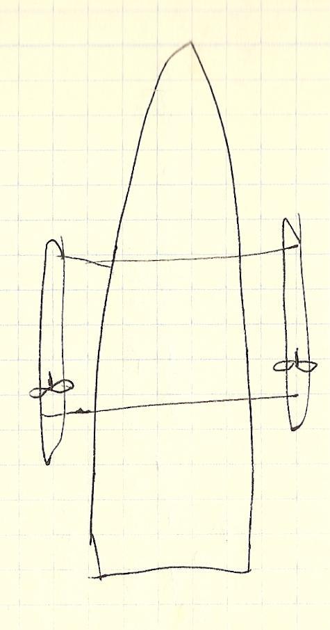
9 Final Design Best Design = Motors attached to Pontoons
10 Risk #1: Buoyancy mg = F b Additional weight- Motor: 3.4 lbs Pipes: 1.16 lbs Bolts: 0.32 lbs Plate: 0.80 lbs Plastic: lbs Total: lbs = kg Marine spray-in foam: Density = 2 lbs/ft 3 = kg/m 3 F b = (V disp w -V disp f ) g = mg V disp = kg 1025 kg/m kg/m 3 = m 3 = 174 in 3 Pontoon could be 3 x3 x20 = 180 in 3 *Will be more to provide safety factor for battery, solar panels, etc.

11 Risk #2: Destructive Disturbances Degree of Freedom constraints Forces and Moments in all directions Stress Calculation

12 Student B Main Failure Modes Spring-Mass Model Wave Forcing Stress Calculations
13 Main Failure Modes Resonance with waves in roll Wave forcing on pontoons Horizontal forcing Vertical forcing Resultant stress on structure, bolts and pipes
14 Resonant Frequency Model as single cantilever beam under point loading Use Euler- Bernoulli Equation EI 4 d u 4 dx w( x) w( x) F ( x L)
15 Model as Spring-Mass System F = -ku, therefore: F 3EI k 3EI L 3 u L 3 Find resonant frequency of system using: k m For boat values, ω = 83Hz ω boat >> ω waves
16 Wave Forcing on Pontoon F F Z F FK Sw pnds kt l2 age cos( t)sin( kb) k L2 age k sin( kb) kt zmax 166 N F x F B = 0.075m, T = 0.1m Worst-case waves : ω= 1Hz A= 0.3m Deep water waves: k Surface pressure integration: F Max 2 m ~ 0.1 kt 2L ag(1 e )sin( t)sin( kb) xmax kt 2L ag(1 e )sin( kb) x 0. 44N
17 Implications of wave forcing Horizontal force on pontoon is negligible Vertical force causes moment Forcing moment: 50Nm. Reaction force on boat structure: 277.8N Could cause: Failure at bend in struts Bolts securing aluminum plate to damage boat structure Internal structure to rip out of boat completely
18 Stress Calculations Bend in pipes Stress calculated using Max stress: 8.8 x 10 6 Pa Yield stress of aluminum: 4 x 10 8 Pa Force on bolts Design distributes load over 6 bolts Total force on each bolt is 46.3N May be too high! MR I Requires more attachment points
19 Failure of Internal Structure Internal bracing mounted with epoxy Pontoon stress may be too large Calculate stress to ensure safety Approximation: stress on epoxy in shear direction Shear force per unit area of epoxy contact: 1.5 x 10 4 Pa Shear strength of epoxy: 1.4 x 10 7 Pa Connection secure! Note: Epoxy is much weaker in peel forcing. However, hull and plate move in tandem, so peel forcing will not occur.
20 Next steps: Analyze plate design adequacy Modify plate design to distribute load Deployment load analysis Vessel stress analysis for true wave spectrum
21 Student E Reading GPS Data GPS Test Results Reading Sonar Data
22 GPS Data Standard Format: GPRMC, ,A, ,N, ,W,4.29,258.17,310809,,*16 Haversine formula: Computes distance between points on sphere lat long a c d a tan 2( lat 2 lat1 sin Rc R = sphere radius long 2 long1 2 ( lat / 2) cos( lat1) cos( lat 2)sin a, (1 a)) 2 ( long / 2)

23 Trial 1

24 TRAIL-2

25 TRAIL-3
26 Transition Point Approximation Pavilion = Position 1 Cruising mode until Position 225: change to wall following 271: return to cruising 304: change to wall following 332: final transition to cruising mode Return to pavilion

27 Position 225

28 Positions
29 3-axis compass OS AXIS compass used Compass contains 2.5V inverting circuit Inverting circuit reads sensor output Result is data string of form: $C...R P T.*1.A

30 Student A Selected Sonar Wall Finding Wall Following Control Architecture
31 LV MaxSonar WR-1 Range inches Analog and serial output Analog accurate 1 of serial output Maintain moving average of analog output Fully waterproofed Mounted to a servo Photo of the MaxSonar WR1 removed due to copyright restrictions.
32 Wall Finding Run at pre-set heading until wall is detected Wall detection at 3.05 m, accurate reliable readings at 2.13 m Safety buffer of 1.52 m from wall
33 Wall Following hw H w h Hb b Calculate wall heading, follow along path H w H b tan 1 d 2 cos( ) d d sin( ) 2 1 d2 θ d1
34 Error (cm) Accuracy Given sonar accuracy ± 2.54 cm Position error over run < 20 cm Optimal theta = radians 20 Position error at end of run Theta (radians)


35 Control Architecture Mission Controller vs. Boat Controller Arduino Mega and Duemilanove Each can be tested in isolation Xbee communications with shore Courtesy of Arduino.cc. Used with permission.

36 Student C Speed Controller Tests Speed Controller Selection Thrust Tests

37 Propulsion System Design 2 Thrusters 1 per outer hull Differential thrust for yaw PWM control with Arduino and Speed Controllers 12V DC Trolling Motors
38 Speed Controller Selection Pro Boat 40A Waterproof ESC Limited PWM frequency range Incompatible with Arduino PWM Victor 884 ESC Compatible with Arduino Not Waterproof Photos removed due to copyright restrictions. Please see: Pro Boat Waterproof ESC with Reverse 5-12V 40A VEX Robotics Victor V Fan

39 Speed Controller Test Pro Boat ESC successfully driven by RC receiver RC PWM signal monitored on O-scope PWM frequency = 55Hz PWM frequency not in Arduino range

40 Thrust Test Test conducted in water tank Thrust was measured at different motor voltages Data fit to linear curve Maximum vehicle thrust=2x28.17n=56.3n Minimum voltage=1.5v Force=Sensor Force X R2/R1
41 Thrust Test Data
42 Student F Characterize wave spectrum of Charles River

43 Setup Flow rate meter LabPro LoggerPro computer Real Term Pressure transducer Arduino microprocessor
44 Flow Data
45 Wave Data
46 Wave Data FFT
47 Wave Periods Average period length =
48 Wave Heights Average 1/3 wave height = cm
49 Autocorrelation
50 Further Work Collect more data Differing weather conditions Create models Heave Pontoons and vessel response
51 Student G Vehicle Requirements Panel Selection Power Output Test System Integration
52 Estimating Requirements Component Voltage Current Power Accelerometer 6V 50mA W Sonar 5V 50mA W GPS 3.3V 50mA W Arduino Mega 5v 50mA 0.25 W Motors (2) (minimum) 12V Electronics Total: Vehicle Total: W
53 Estimating Capabilities Standard Rating Conditions: 1000 W/m 2 SRCs correct for Power in W/m Sun Power Density Time of Day in Hours Standard Conditions Boston Conditions
54 Correcting Specifications Panel output: P out panel E density A Morning deployment to minimize waves Ideal Mission Conditions: 10am in Boston on sunny day Mission E density = 600 W/m 2 Non-ideal Mission Conditions: 10am in Boston on cloudy day Mission E density = 200 W/m 2 panel
 2W (cloudy)) Total cost:")
55 Suntech STP Peak Rated Power = 5W Peak Power (sunny)= 3W Peak Power (rainy) = 1W Purchased 2 12 x18 panels Final Estimated Capability: 10W max 6W (sun) 2W (cloudy)) Total cost: $120.00
56 Testing the Panels Measured Short Circuit Current ~ 0.21 Amps Rated Short Circuit Current = 0.33 Amps Measured Power Output = 2.8 Watts Voltage (V) Power Curve for Suntech Panel on Sunny Day Current (A)
57 Control Architecture Time index from GPS Heading from compass Sun Position Information Servo-actuated panel repositions to optimize power

58 System Integration
59
60 Significant Risks and Mitigations Mitigated with good planning: Major construction setbacks Mitigated with testing and debugging: Poor power management Sensor Failure (GPS) Data Interpretation Failure Motor or Boat Controller Failure Uncontrollable: Inclement weather
61 Next Steps Finish construction Vessel: pontoons, solar panel support Integrate sensors and structure Control System Implementation Testing Yaw dynamic Tow Tank test Wall-following Tow Tank test Troubleshoot Mission Day!
62 Questions?
63 MIT OpenCourseWare J Design of Electromechanical Robotic Systems Fall 2009 For information about citing these materials or our Terms of Use, visit:
OPERATION AND MAINTENANCE MANUAL TRIAXIAL ACCELEROMETER MODEL PA-23 STOCK NO
 OPERATION AND MAINTENANCE MANUAL TRIAXIAL ACCELEROMETER MODEL PA-23 STOCK NO. 990-60700-9801 GEOTECH INSTRUMENTS, LLC 10755 SANDEN DRIVE DALLAS, TEXAS 75238-1336 TEL: (214) 221-0000 FAX: (214) 343-4400
GPS System Design and Control Modeling. Chua Shyan Jin, Ronald. Assoc. Prof Gerard Leng. Aeronautical Engineering Group, NUS
 GPS System Design and Control Modeling Chua Shyan Jin, Ronald Assoc. Prof Gerard Leng Aeronautical Engineering Group, NUS Abstract A GPS system for the autonomous navigation and surveillance of an airship
2.017 DESIGN OF ELECTROMECHANICAL ROBOTIC SYSTEMS Fall 2009 Lab 3: GPS and Data Logging. September 28, 2009 Dr. Harrison H. Chin
 2.017 DESIGN OF ELECTROMECHANICAL ROBOTIC SYSTEMS Fall 2009 Lab 3: GPS and Data Logging September 28, 2009 Dr. Harrison H. Chin Formal Labs 1. Microcontrollers Introduction to microcontrollers Arduino
Introducing the Quadrotor Flying Robot
 Introducing the Quadrotor Flying Robot Roy Brewer Organizer Philadelphia Robotics Meetup Group August 13, 2009 What is a Quadrotor? A vehicle having 4 rotors (propellers) at each end of a square cross
Engtek SubSea Systems
 Engtek SubSea Systems A Division of Engtek Manoeuvra Systems Pte Ltd SubSea Propulsion Technology AUV Propulsion and Maneuvering Modules Engtek SubSea Systems A Division of Engtek Manoeuvra Systems Pte
Response spectrum Time history Power Spectral Density, PSD
 A description is given of one way to implement an earthquake test where the test severities are specified by time histories. The test is done by using a biaxial computer aided servohydraulic test rig.
Final Design Report. Project Title: Multi-Function Pontoon (MFP)
") EEL 4924 Electrical Engineering Design (Senior Design) Final Design Report 25 April 2012 Project Title: Multi-Function Pontoon (MFP) Team Members: Name: Mikkel Gabbadon Name: Sheng-Po Fang Project Abstract:
EEL 4924 Electrical Engineering Design (Senior Design) Final Design Report 25 April 2012 Project Title: Multi-Function Pontoon (MFP) Team Members: Name: Mikkel Gabbadon Name: Sheng-Po Fang Project Abstract:
TEAM AERO-I TEAM AERO-I JOURNAL PAPER DELHI TECHNOLOGICAL UNIVERSITY Journal paper for IARC 2014
 TEAM AERO-I TEAM AERO-I JOURNAL PAPER DELHI TECHNOLOGICAL UNIVERSITY DELHI TECHNOLOGICAL UNIVERSITY Journal paper for IARC 2014 2014 IARC ABSTRACT The paper gives prominence to the technical details of
Design and Navigation Control of an Advanced Level CANSAT. Mansur ÇELEBİ Aeronautics and Space Technologies Institute Turkish Air Force Academy
 Design and Navigation Control of an Advanced Level CANSAT Mansur ÇELEBİ Aeronautics and Space Technologies Institute Turkish Air Force Academy 1 Introduction Content Advanced Level CanSat Design Airframe
CDS 101/110a: Lecture 8-1 Frequency Domain Design
 CDS 11/11a: Lecture 8-1 Frequency Domain Design Richard M. Murray 17 November 28 Goals: Describe canonical control design problem and standard performance measures Show how to use loop shaping to achieve
University of Florida Department of Electrical and Computer Engineering Intelligent Machine Design Laboratory EEL 4665 Spring 2013 LOSAT
 University of Florida Department of Electrical and Computer Engineering Intelligent Machine Design Laboratory EEL 4665 Spring 2013 LOSAT Brandon J. Patton Instructors: Drs. Antonio Arroyo and Eric Schwartz
Application Information
 Application Information Magnetic Encoder Design for Electrical Motor Driving Using ATS605LSG By Yannick Vuillermet and Andrea Foletto, Allegro MicroSystems Europe Ltd Introduction Encoders are normally
FLCS V2.1. AHRS, Autopilot, Gyro Stabilized Gimbals Control, Ground Control Station
 AHRS, Autopilot, Gyro Stabilized Gimbals Control, Ground Control Station The platform provides a high performance basis for electromechanical system control. Originally designed for autonomous aerial vehicle
Robotics Challenge. Team Members Tyler Quintana Tyler Gus Josh Cogdill Raul Davila John Augustine Kelty Tobin
 Robotics Challenge Team Members Tyler Quintana Tyler Gus Josh Cogdill Raul Davila John Augustine Kelty Tobin 1 Robotics Challenge: Team Multidisciplinary: Computer, Electrical, Mechanical Currently split
AUTOPILOT CONTROL SYSTEM - IV
 AUTOPILOT CONTROL SYSTEM - IV CONTROLLER The data from the inertial measurement unit is taken into the controller for processing. The input being analog requires to be passed through an ADC before being
Optimizing Performance Using Slotless Motors. Mark Holcomb, Celera Motion
 Optimizing Performance Using Slotless Motors Mark Holcomb, Celera Motion Agenda 1. How PWM drives interact with motor resistance and inductance 2. Ways to reduce motor heating 3. Locked rotor test vs.
Preliminary study of the vibration displacement measurement by using strain gauge
 Songklanakarin J. Sci. Technol. 32 (5), 453-459, Sep. - Oct. 2010 Original Article Preliminary study of the vibration displacement measurement by using strain gauge Siripong Eamchaimongkol* Department
Pre Test 1. Name. a Hz b Hz c Hz d Hz e Hz. 1. d
 Name Pre Test 1 1. The wavelength of light visible to the human eye is on the order of 5 10 7 m. If the speed of light in air is 3 10 8 m/s, find the frequency of the light wave. 1. d a. 3 10 7 Hz b. 4
SRV02-Series Rotary Experiment # 3. Ball & Beam. Student Handout
 SRV02-Series Rotary Experiment # 3 Ball & Beam Student Handout SRV02-Series Rotary Experiment # 3 Ball & Beam Student Handout 1. Objectives The objective in this experiment is to design a controller for
A Machine Tool Controller using Cascaded Servo Loops and Multiple Feedback Sensors per Axis
 A Machine Tool Controller using Cascaded Servo Loops and Multiple Sensors per Axis David J. Hopkins, Timm A. Wulff, George F. Weinert Lawrence Livermore National Laboratory 7000 East Ave, L-792, Livermore,
Classical Control Based Autopilot Design Using PC/104
 Classical Control Based Autopilot Design Using PC/104 Mohammed A. Elsadig, Alneelain University, Dr. Mohammed A. Hussien, Alneelain University. Abstract Many recent papers have been written in unmanned
Real-Time Control of a Remotely Operated Vessel
 Real-Time Control of a Remotely Operated Vessel R. BACHNAK, C. STEIDLEY, M. MENDEZ, J. ESPARZA, D. DAVIS Department of Computing and Mathematical Sciences Texas A&M University-Corpus Christi 6300 Ocean
im200 Payload Autonomy Interface for Heron USVs
 im200 Payload Autonomy Interface for Heron USVs Fall 2017 Alon Yaari, ayaari@mit.edu Michael Benjamin, mikerb@mit.edu Department of Mechanical Engineering, CSAIL MIT, Cambridge MA 02139 1 im200 Payload
HexGen HEX HL Hexapod Six-DOF Positioning System
 HexGen HE300-230HL Hexapods and Robotics HexGen HE300-230HL Hexapod Six-DOF Positioning System Six degree-of-freedom positioning with linear travels to 60 mm and angular travels to 30 Precision design
Active Vibration Isolation of an Unbalanced Machine Tool Spindle
 Active Vibration Isolation of an Unbalanced Machine Tool Spindle David. J. Hopkins, Paul Geraghty Lawrence Livermore National Laboratory 7000 East Ave, MS/L-792, Livermore, CA. 94550 Abstract Proper configurations
Hopper Spacecraft Simulator. Billy Hau and Brian Wisniewski
 Hopper Spacecraft Simulator Billy Hau and Brian Wisniewski Agenda Introduction Flight Dynamics Hardware Design Avionics Control System Future Works Introduction Mission Overview Collaboration with Penn
The Mathematics of the Stewart Platform
 The Mathematics of the Stewart Platform The Stewart Platform consists of 2 rigid frames connected by 6 variable length legs. The Base is considered to be the reference frame work, with orthogonal axes
SONOBOT AUTONOMOUS HYDROGRAPHIC SURVEY VEHICLE PRODUCT INFORMATION GUIDE
 SONOBOT AUTONOMOUS HYDROGRAPHIC SURVEY VEHICLE PRODUCT INFORMATION GUIDE EvoLogics Sonobot an autonomous unmanned surface vehicle for hydrographic surveys High Precision Differential GPS for high-accuracy
Technology Considerations for Advanced Formation Flight Systems
 Technology Considerations for Advanced Formation Flight Systems Prof. R. John Hansman MIT International Center for Air Transportation How Can Technologies Impact System Concept Need (Technology Pull) Technologies
HexGen HEX HL Hexapod Six-DOF Positioning System
 HexGen HE300-230HL Hexapods and Robotics HexGen HE300-230HL Hexapod Six-DOF Positioning System Six degree-of-freedom positioning with linear travels to 60 mm and angular travels to 30 Precision design
Project Report Liquid Robotics, Inc. Integration and Use of a High-frequency Acoustic Recording Package (HARP) on a Wave Glider
 on a Wave Glider") Project Report Liquid Robotics, Inc. Integration and Use of a High-frequency Acoustic Recording Package (HARP) on a Wave Glider Sean M. Wiggins Marine Physical Laboratory Scripps Institution of Oceanography
Project Report Liquid Robotics, Inc. Integration and Use of a High-frequency Acoustic Recording Package (HARP) on a Wave Glider Sean M. Wiggins Marine Physical Laboratory Scripps Institution of Oceanography
Chapter 30: Principles of Active Vibration Control: Piezoelectric Accelerometers
 Chapter 30: Principles of Active Vibration Control: Piezoelectric Accelerometers Introduction: Active vibration control is defined as a technique in which the vibration of a structure is reduced or controlled
ENGR-4300 Electronic Instrumentation Quiz 2 Fall 2011 Name Section
 ENGR-43 Quiz 2 Fall 211 ENGR-43 Electronic Instrumentation Quiz 2 Fall 211 Name Section Question I (2 points) Question II (2 points) Question III (2 points) Question I (2 points) Question (2 points) Total
INSTRUCTIONS. 3DR Plane CONTENTS. Thank you for purchasing a 3DR Plane!
 DR Plane INSTRUCTIONS Thank you for purchasing a DR Plane! CONTENTS 1 1 Fuselage Right wing Left wing Horizontal stabilizer Vertical stabilizer Carbon fiber bar 1 1 1 7 8 10 11 1 Audio/video (AV) cable
DA DA 26 Technical Specification. Page 1/27. Volz Servos GmbH & Co. KG servos.com
 1/27 DA 26 DA 26 30 5024 2/27 Content 1. General Description... 3 2. Operating Data... 4 3. Performance... 5 4. Command Signal... 6 4.1. PWM Command Interface... 6 4.2. RS 485 Command Signal... 6 4.3.
HexGen HEX HL Hexapod Six-DOF Positioning System
 HexGen HE300-230HL Hexapods and Robotics HexGen HE300-230HL Hexapod Six-DOF Positioning System Six degree-of-freedom positioning with linear travels to 60 mm and angular travels to 30 Precision design
Hardware in the Loop Simulation for Unmanned Aerial Vehicles
 NATIONAL 1 AEROSPACE LABORATORIES BANGALORE-560 017 INDIA CSIR-NAL Hardware in the Loop Simulation for Unmanned Aerial Vehicles Shikha Jain Kamali C Scientist, Flight Mechanics and Control Division National
HPC Compass NMEA Version. Installation and Operation Manual
 HPC Compass NMEA Version Installation and Operation Manual NMEA HPC COMPASS 13-1 NMEA HPC COMPASS This manual is written for the NMEA HPC Compass transducer 1.1 Edition: 1.4 May 2010 13-2 NMEA HPC COMPASS
DA 30 High Torque Technical Specification
 1/17 DA 30 High Torque DA 30-HT-30-5848 2/17 Content 1. General Description... 3 2. Operating Data... 4 3. Performance... 5 4. Materials and Protective Features... 6 5. Dimensions... 6 5.1. Installation
Electronic Concepts and Troubleshooting 101. Experiment 1
 Electronic Concepts and Troubleshooting 101 Experiment 1 o Concept: What is the capacity of a typical alkaline 1.5V D-Cell? o TS: Assume that a battery is connected to a 20Ω load and the voltage across
Low cost underwater exploration vehicle
 PROJECT N 36 Low cost underwater exploration vehicle David O Brien-Møller European School Brussels III Boulevard du Triomphe 135, 1050 Ixelles, Belgique S6 ENA Abstract Key words: Under Water robot, independent
MODEL Sx SERVOTUBE MODULE
 Force» Peak: 156-780 N» Continuous: 42-102 N Maximum Velocity» Up to 8.5 m/s Feedback» Built-in position sensor» 1V pk-pk sin/cos» 12 micron repeatability» Optionally with high resolution encoder Range
(i) Sine sweep (ii) Sine beat (iii) Time history (iv) Continuous sine
 Sine sweep (ii) Sine beat (iii) Time history (iv) Continuous sine") A description is given of one way to implement an earthquake test where the test severities are specified by the sine-beat method. The test is done by using a biaxial computer aided servohydraulic test
A description is given of one way to implement an earthquake test where the test severities are specified by the sine-beat method. The test is done by using a biaxial computer aided servohydraulic test
MODELS SM SERVOTUBE MODULE
 Force» Peak: 46-92 N» Continuous: 6-27 N Maximum Velocity» Up to 10.8 m/s Feedback» Built-in position sensor» 1V pk-pk sin/cos» 6 micron repeatability» Optionally with high resolution encoder Range of
PHYS102 Previous Exam Problems. Sound Waves. If the speed of sound in air is not given in the problem, take it as 343 m/s.
 PHYS102 Previous Exam Problems CHAPTER 17 Sound Waves Sound waves Interference of sound waves Intensity & level Resonance in tubes Doppler effect If the speed of sound in air is not given in the problem,
DC motor control using arduino
 DC motor control using arduino 1) Introduction: First we need to differentiate between DC motor and DC generator and where we can use it in this experiment. What is the main different between the DC-motor,
Motomatic Servo Control
 Exercise 2 Motomatic Servo Control This exercise will take two weeks. You will work in teams of two. 2.0 Prelab Read through this exercise in the lab manual. Using Appendix B as a reference, create a block
Magnetic Levitation System
 Magnetic Levitation System Electromagnet Infrared LED Phototransistor Levitated Ball Magnetic Levitation System K. Craig 1 Magnetic Levitation System Electromagnet Emitter Infrared LED i Detector Phototransistor
TRIALLIANCE FABRICATING: Mertztown, PA Job #2
 Report on Vibratory Stress Relief Prepared by Bruce B. Klauba Product Group Manager TRIALLIANCE FABRICATING: Mertztown, PA Job #2 TRIALLIANCE FABRICATING, a steel fabricator, subcontracted VSR Technology
SMART BIRD TEAM UAS JOURNAL PAPER
 SMART BIRD TEAM UAS JOURNAL PAPER 2010 AUVSI STUDENT COMPETITION MARYLAND ECOLE POLYTECHNIQUE DE MONTREAL Summary 1 Introduction... 4 2 Requirements of the competition... 4 3 System Design... 5 3.1 Design
The Torxis Linear Servo meets the following environmental conditions:
 Page: 1 1. PRODUCT DESCRIPTION The Torxis Linear Servo is the second generation of linear servos provided by GearWurx. This product features internal position sensing, and closed loop position control.
Development of a Ball and Plate System
 Paper ID #12313 Development of a Ball and Plate System Dr. Chan Ham, Kennesaw State University He is an Associate Professor in Mechatronics Engineering at the Kennesaw State University. He has over fifteen
SELF STABILIZING PLATFORM
 SELF STABILIZING PLATFORM Shalaka Turalkar 1, Omkar Padvekar 2, Nikhil Chavan 3, Pritam Sawant 4 and Project Guide: Mr Prathamesh Indulkar 5. 1,2,3,4,5 Department of Electronics and Telecommunication,
UIC PHYSICS 105 Fall 2014 Final Exam
 UIC: Physics 105 Final Exam Fall 2014 Wednesday, December 10 # LAST Name (print) FIRST Name (print) Signature: UIN #: Giving or receiving aid in any examination is cause for dismissal from the University.
The plan... CSE 6324 From control to actuators Michael Jenkin Office Hours: Sherman 1028 Wed 3-4. From the bottom up...
 The plan... CSE 6324 From control to actuators Michael Jenkin jenkin@cse.yorku.ca Office Hours: Sherman 1028 Wed 3-4 Lectures this week No class next week Start building the week after (i) Need to sort
Report on Vibratory Stress Relief Prepared by Bruce B. Klauba Product Group Manager
 Report on Vibratory Stress Relief Prepared by Bruce B. Klauba Product Group Manager CAMERON COMPRESSION SYSTEM DIVISION Oklahoma City, OK The Compression Systems Division of CAMERON (formerly COOPER COMPRESSION,
FOXTECH Nimbus VTOL. User Manual V1.1
 FOXTECH Nimbus VTOL User Manual V1.1 2018.01 Contents Specifications Basic Theory Introduction Setup and Calibration Assembly Control Surface Calibration Compass and Airspeed Calibration Test Flight Autopilot
Total Hours Registration through Website or for further details please visit (Refer Upcoming Events Section)
") Total Hours 110-150 Registration Q R Code Registration through Website or for further details please visit http://www.rknec.edu/ (Refer Upcoming Events Section) Module 1: Basics of Microprocessor & Microcontroller
Total Hours 110-150 Registration Q R Code Registration through Website or for further details please visit http://www.rknec.edu/ (Refer Upcoming Events Section) Module 1: Basics of Microprocessor & Microcontroller
Introduction: Components used:
 Introduction: As, this robotic arm is automatic in a way that it can decides where to move and when to move, therefore it works in a closed loop system where sensor detects if there is any object in a
PE Electrical Machine / Power Electronics. Power Electronics Training System. ufeatures. } List of Experiments
 Electrical Machine / Power Electronics PE-5000 Power Electronics Training System The PE-5000 Power Electronics Training System consists of 28 experimental modules, a three-phase squirrel cage motor, load,
INSTRUCTION MANUAL TRI-PLATE LINE MODEL EM-7310
 INSTRUCTION MANUAL TRI-PLATE LINE MODEL EM-7310 INSTRUCTION MANUAL THIS INSTRUCTION MANUAL AND ITS ASSOCIATED INFORMATION IS PRO- PRIETARY. UNAUTHORIZED REPRO- DUCTION IS FORBIDDEN. 1998 ELECTRO-METRICS
Teaching Mechanical Students to Build and Analyze Motor Controllers
 Teaching Mechanical Students to Build and Analyze Motor Controllers Hugh Jack, Associate Professor Padnos School of Engineering Grand Valley State University Grand Rapids, MI email: jackh@gvsu.edu Session
MB1013, MB1023, MB1033, MB1043
 HRLV-MaxSonar - EZ Series HRLV-MaxSonar - EZ Series High Resolution, Low Voltage Ultra Sonic Range Finder MB1003, MB1013, MB1023, MB1033, MB1043 The HRLV-MaxSonar-EZ sensor line is the most cost-effective
b) (4) How large is the effective spring constant associated with the oscillations, in N/m?
 (4) How large is the effective spring constant associated with the oscillations, in N/m?") General Physics I Quiz 7 - Ch. 11 - Vibrations & Waves July 22, 2009 Name: Make your work clear to the grader. Show formulas used. Give correct units and significant figures. Partial credit is available
General Physics I Quiz 7 - Ch. 11 - Vibrations & Waves July 22, 2009 Name: Make your work clear to the grader. Show formulas used. Give correct units and significant figures. Partial credit is available
Autonomous Following RObot Initial Design Review
 Autonomous Following RObot Initial Design Review James Tse (Leader) Wei Dai Travis Frecker Peter Verlangieri Professor John Johnson ECE 189A Fall 2012 Initial Design Review: Project Description Original
Module 4 TEST SYSTEM Part 2. SHAKING TABLE CONTROLLER ASSOCIATED SOFTWARES Dr. J.C. QUEVAL, CEA/Saclay
 Module 4 TEST SYSTEM Part 2 SHAKING TABLE CONTROLLER ASSOCIATED SOFTWARES Dr. J.C. QUEVAL, CEA/Saclay DEN/DM2S/SEMT/EMSI 11/03/2010 1 2 Electronic command Basic closed loop control The basic closed loop
Modeling and Control of Mold Oscillation
 ANNUAL REPORT UIUC, August 8, Modeling and Control of Mold Oscillation Vivek Natarajan (Ph.D. Student), Joseph Bentsman Department of Mechanical Science and Engineering University of Illinois at UrbanaChampaign
PID-CONTROL FUNCTION AND APPLICATION
 PID-CONTROL FUNCTION AND APPLICATION Hitachi Inverters SJ1 and L1 Series Deviation - P : Proportional operation I : Integral operation D : Differential operation Inverter Frequency command Fan, pump, etc.
Design and Development of Novel Two Axis Servo Control Mechanism
 Design and Development of Novel Two Axis Servo Control Mechanism Shailaja Kurode, Chinmay Dharmadhikari, Mrinmay Atre, Aniruddha Katti, Shubham Shambharkar Abstract This paper presents design and development
Interfacing dspace to the Quanser Rotary Series of Experiments (SRV02ET)
") Interfacing dspace to the Quanser Rotary Series of Experiments (SRV02ET) Nicanor Quijano and Kevin M. Passino The Ohio State University, Department of Electrical Engineering, 2015 Neil Avenue, Columbus
Interfacing dspace to the Quanser Rotary Series of Experiments (SRV02ET) Nicanor Quijano and Kevin M. Passino The Ohio State University, Department of Electrical Engineering, 2015 Neil Avenue, Columbus
Vibratory Feeder Bowl Analysis
 The Journal of Undergraduate Research Volume 7 Journal of Undergraduate Research, Volume 7: 2009 Article 7 2009 Vibratory Feeder Bowl Analysis Chris Green South Dakota State University Jeff Kreul South
Abstract. 1. Introduction
 Trans Am: An Experiment in Autonomous Navigation Jason W. Grzywna, Dr. A. Antonio Arroyo Machine Intelligence Laboratory Dept. of Electrical Engineering University of Florida, USA Tel. (352) 392-6605 Email:
Physics 4C Chabot College Scott Hildreth
 Physics 4C Chabot College Scott Hildreth The Inverse Square Law for Light Intensity vs. Distance Using Microwaves Experiment Goals: Experimentally test the inverse square law for light using Microwaves.
Team Description 2006 for Team RO-PE A
 Team Description 2006 for Team RO-PE A Chew Chee-Meng, Samuel Mui, Lim Tongli, Ma Chongyou, and Estella Ngan National University of Singapore, 119260 Singapore {mpeccm, g0500307, u0204894, u0406389, u0406316}@nus.edu.sg
Testing Autonomous Hover Algorithms Using a Quad rotor Helicopter Test Bed
 Testing Autonomous Hover Algorithms Using a Quad rotor Helicopter Test Bed In conjunction with University of Washington Distributed Space Systems Lab Justin Palm Andy Bradford Andrew Nelson Milestone One
Administrative Notes. DC Motors; Torque and Gearing; Encoders; Motor Control. Today. Early DC Motors. Friday 1pm: Communications lecture
 At Actuation: ti DC Motors; Torque and Gearing; Encoders; Motor Control RSS Lecture 3 Wednesday, 11 Feb 2009 Prof. Seth Teller Administrative Notes Friday 1pm: Communications lecture Discuss: writing up
SOLVING VIBRATIONAL RESONANCE ON A LARGE SLENDER BOAT USING A TUNED MASS DAMPER. A.W. Vredeveldt, TNO, The Netherlands
 SOLVING VIBRATIONAL RESONANCE ON A LARGE SLENDER BOAT USING A TUNED MASS DAMPER. A.W. Vredeveldt, TNO, The Netherlands SUMMARY In luxury yacht building, there is a tendency towards larger sizes, sometime
Experiment 9 : Pulse Width Modulation
 Name/NetID: Experiment 9 : Pulse Width Modulation Laboratory Outline In experiment 5 we learned how to control the speed of a DC motor using a variable resistor. This week, we will learn an alternative
TRI-ALLIANCE FABRICATING Mertztown, PA Job #1
 Report on Vibratory Stress Relief Prepared by Bruce B. Klauba Product Group Manager TRI-ALLIANCE FABRICATING Mertztown, PA Job #1 TRI-ALLIANCE FABRICATING subcontracted VSR TECHNOLOGY to stress relieve
العطاء رقم )7106/67( الخاص بشراء أجهز لقسم الهندسة الكهربائية على حساب البحث العلمي
7106/67( الخاص بشراء أجهز لقسم الهندسة الكهربائية على حساب البحث العلمي") العطاء رقم )7106/67( الخاص بشراء أجهز لقسم الهندسة الكهربائية على حساب البحث العلمي رقم )7107/363( Page 1 of 6 1- Mechatronics Actuators Board & Mechatronics Systems Board with Education Laboratory for
العطاء رقم )7106/67( الخاص بشراء أجهز لقسم الهندسة الكهربائية على حساب البحث العلمي رقم )7107/363( Page 1 of 6 1- Mechatronics Actuators Board & Mechatronics Systems Board with Education Laboratory for
THE PRINCIPLE OF LINEAR SUPERPOSITION AND INTERFERENCE PHENOMENA
 THE PRINCIPLE OF LINEAR SUPERPOSITION AND INTERFERENCE PHENOMENA PREVIEW When two waves meet in the same medium they combine to form a new wave by the principle of superposition. The result of superposition
MEM380 Applied Autonomous Robots I Winter Feedback Control USARSim
 MEM380 Applied Autonomous Robots I Winter 2011 Feedback Control USARSim Transforming Accelerations into Position Estimates In a perfect world It s not a perfect world. We have noise and bias in our acceleration
Satellite Testing. Prepared by. A.Kaviyarasu Assistant Professor Department of Aerospace Engineering Madras Institute Of Technology Chromepet, Chennai
 Satellite Testing Prepared by A.Kaviyarasu Assistant Professor Department of Aerospace Engineering Madras Institute Of Technology Chromepet, Chennai @copyright Solar Panel Deployment Test Spacecraft operating
2 Study of an embarked vibro-impact system: experimental analysis
 2 Study of an embarked vibro-impact system: experimental analysis This chapter presents and discusses the experimental part of the thesis. Two test rigs were built at the Dynamics and Vibrations laboratory
Electronics Design Laboratory Lecture #4. ECEN 2270 Electronics Design Laboratory
 Electronics Design Laboratory Lecture #4 Electronics Design Laboratory 1 Part A Experiment 2 Robot DC Motor Measure DC motor characteristics Develop a Spice circuit model for the DC motor and determine
Flight control Set and Kit
 Flight control Set and Kit Quick Start Guide For MegaPirate NG Version 1.2 Thanks for choosing AirStudio flight control electronics. We have created it based on best-in-class software, hardware and our
DEVELOPMENT OF THE HUMANOID ROBOT HUBO-FX-1
 DEVELOPMENT OF THE HUMANOID ROBOT HUBO-FX-1 Jungho Lee, KAIST, Republic of Korea, jungho77@kaist.ac.kr Jung-Yup Kim, KAIST, Republic of Korea, kirk1@mclab3.kaist.ac.kr Ill-Woo Park, KAIST, Republic of
Dynamic Modeling of Air Cushion Vehicles
 Proceedings of IMECE 27 27 ASME International Mechanical Engineering Congress Seattle, Washington, November -5, 27 IMECE 27-4 Dynamic Modeling of Air Cushion Vehicles M Pollack / Applied Physical Sciences
Study of M.A.R.S. (Multifunctional Aero-drone for Remote Surveillance)
") Study of M.A.R.S. (Multifunctional Aero-drone for Remote Surveillance) Supriya Bhuran 1, Rohit V. Agrawal 2, Kiran D. Bombe 2, Somiran T. Karmakar 2, Ninad V. Bapat 2 1 Assistant Professor, Dept. Instrumentation,
Study of M.A.R.S. (Multifunctional Aero-drone for Remote Surveillance) Supriya Bhuran 1, Rohit V. Agrawal 2, Kiran D. Bombe 2, Somiran T. Karmakar 2, Ninad V. Bapat 2 1 Assistant Professor, Dept. Instrumentation,
Schematics for Breakout Examples
 Schematics for Breakout Examples This document contains wiring diagrams and component lists for the examples. A diagram may be used for more than one example file. The corresponding files are listed for
Instrument Cluster Display. Grant Scott III Erin Lawler Mike Carlson
 Instrument Cluster Display Grant Scott III Erin Lawler Mike Carlson ECE 570 December 4 th, 2014 Presentation Outline Introduction and Motivation Features Temperature Sensing LCD Display Fahrenheit/Celsius
Design and Analysis of Spindle for Oil Country Lathe
 Design and Analysis of Spindle for Oil Country Lathe Maikel Raj K 1, Dr. Soma V Chetty 2 P.G. Student, Department of Mechanical Engineering, Kuppam Engineering College, Kuppam, Chittoor, India 1 Principal,
Preliminary Design Review
 Proximity Identification, characterization, And Neutralization by thinking before Acquisition (PIRANHA) Preliminary Design Review Customer: Barbara Bicknell Jeffrey Weber Team: Aaron Buysse Kevin Rauhauser
Applications of iusbl Technology overview
 Applications of iusbl Technology overview Tom Bennetts Project Manager Summary 1. What is iusbl and its target applications 2. Advantages of iusbl and sample data 3. Technical hurdles and Calibration methods
TigreSAT 2010 &2011 June Monthly Report
 2010-2011 TigreSAT Monthly Progress Report EQUIS ADS 2010 PAYLOAD No changes have been done to the payload since it had passed all the tests, requirements and integration that are necessary for LSU HASP
Pan-Tilt Signature System
 Pan-Tilt Signature System Pan-Tilt Signature System Rob Gillette Matt Cieloszyk Luke Bowen Final Presentation Introduction Problem Statement: We proposed to build a device that would mimic human script
Ball Balancing on a Beam
 1 Ball Balancing on a Beam Muhammad Hasan Jafry, Haseeb Tariq, Abubakr Muhammad Department of Electrical Engineering, LUMS School of Science and Engineering, Pakistan Email: {14100105,14100040}@lums.edu.pk,
Riser Lifecycle Monitoring System (RLMS) for Integrity Management
 for Integrity Management") Riser Lifecycle Monitoring System (RLMS) for Integrity Management 11121-5402-01 Judith Guzzo GE Global Research Ultra-Deepwater Floating Facilities and Risers & Systems Engineering TAC meeting June 5,
Riser Lifecycle Monitoring System (RLMS) for Integrity Management 11121-5402-01 Judith Guzzo GE Global Research Ultra-Deepwater Floating Facilities and Risers & Systems Engineering TAC meeting June 5,
Implementation of Nonlinear Reconfigurable Controllers for Autonomous Unmanned Vehicles
 Implementation of Nonlinear Reconfigurable Controllers for Autonomous Unmanned Vehicles Dere Schmitz Vijayaumar Janardhan S. N. Balarishnan Department of Mechanical and Aerospace engineering and Engineering
Ranger USBL Acoustic Positioning System for DP Reference and Survey
 Acoustic Positioning System for DP Reference and Survey cc 545000m N 544990m 544980m 544970m 6027910m 6027900m W 6027890m 6027880m S Contents Introduction 01 Ranger USBL System Overview 02 Ranger USBL