Research Article Water Vapor Sensors Based on the Swelling of Relief Gelatin Gratings
|
|
|
- Barbra Young
- 5 years ago
- Views:
Transcription
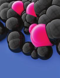
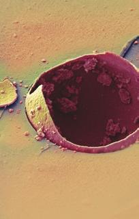
1 Advances in Materials Science and Engineering Volume 2015, Article ID , 5 pages Research Article Water Vapor Sensors Based on the Swelling of Relief Gelatin Gratings Sergio Calixto 1 and Miguel V. Andres 2 1 Centro de Investigaciones en Optica, Loma del Bosque 115, León, GTO, Mexico 2 Departamento de Fisica Aplicada y Electromagnetismo, Universidad de Valencia, Dr. Moliner 50, Burjassot, València, Spain Correspondence should be addressed to Sergio Calixto; scalixto@cio.mx Received 4 December 2014; Revised 27 February 2015; Accepted 11 March 2015 Academic Editor: Luigi Nicolais Copyright 2015 S. Calixto and M. V. Andres. This is an open access article distributed under the Creative Commons Attribution License, which permits unrestricted use, distribution, and reproduction in any medium, provided the original work is properly cited. We report on a novel device to measure relative humidity. The sensor is based on surface diffraction gratings made of gelatin. This material swells and shrinks according to the content of water vapor in air. By sending a light beam to the grating, diffracted orders appear. Due to the gelatin swelling or shrinking, first order intensity changes according to the relative humidity. Calibration curves relating intensity versus relative humidity have been found. The fabrication process of diffraction gratings and the testing of the prototype sensing devices are described. 1. Introduction Devices like sensors and transducers devoted to collect thedatafromthephysicalworldhavedevelopedslowly. Thus, new and better sensors should be made. These new sensors should be sufficiently accurate or suitable for most industrial applications. The content of water in air (or water vapor) is important [1] in various industries like medical andhealthindustry(humiditycontrolledhospitaloperation rooms, incubators, and air conditioning), automotive industry (window defogger), food processing industry (food dehydration), meteorological industry, semiconductor industry (clean rooms), building and construction industry, and more. Ideal humidity sensors should fulfill requirements like (a) good reproducibility over a wide range, (b) short response time, (c) small hysteresis, (d) good durability and long life, (e) resistance against contaminants, (f) low cost, (g) sensitivity to themeasuredpropertyonly,(h)notinfluencingthemeasured property, and more. However, it is difficult to find a humidity sensor that fulfills the mentioned characteristics. For this reason many different measurement methods and sensors have been developed, each having certain advantages and limitations and each suitable for some but not all applications. Among the conventional techniques for humidity detection [2] is the mechanical hygrometer where materials expand and contract in proportion to humidity change. Common materials include synthetic fibers and the human hair. The method is inexpensive but slow and presents nonlinearity and hysteresis. Other techniques are, for example, the chilled mirror hygrometer [2] based on a temperature-controlled reflective condensation mirror, infrared [2], and Lyman-alpha instruments and those based on optical [2] fibersandmemstechnology[3, 4]. These MEMS-based sensors use electronic devices that cannot be used in flammable environments because they introduce a spark risk. Every type of humidity sensors has found a niche market where its performance characteristics apply. But new requirements for humidity measurements are coming up. Here we present the use of a spark-free optical method that uses diffraction gratings as sensors. It is an alternative method to measure relative humidity (RH). In Section 2 we present the material used to fabricate the grating sensor. Section 3 describes the diffraction gratings fabrication method. Section 4 presents the gelatin grating behavior as a function of relative humidity. Section 5 describes the principles of the measuring method and calibration plots and in Section 6 we conclude the paper.
2 2 Advances in Materials Science and Engineering 2. Gelatin Materials used in the measurement of relative humidity are of different kinds. Some commercial humidity sensors work on the basis of transduction of water vapor concentration into an electrical measurement by a sensing film [1, 3, 4]. Among the materials used to fabricate these films are porous ceramics, polymers, and polyelectrolytes. We have used a material that is highly hygroscopic, gelatin. This characteristic isduetothehighnumberofpolargroups[5]initsmolecular structure. Water molecules are absorbed and adsorbed by the gelatinfilmssurfacewheretherearephysicalandchemical interactions. Also there are modifications in the bulk of the film due to water accumulation on and diffusion into the film. When gelatin absorbs water molecules it swells and under desorption it shrinks. Another characteristic of gelatin is that it can be hardened by chemical or optical methods. Among the last methods is the one that uses dichromates. The next steps are followed to harden the gelatin [6]. A gelatin thin film is made by pouringasmallamountofasolutionofgelatinandwater onto a glass substrate. After drying, plates are sensitized in an ammonium dichromate water solution. Then plates are left overnight in a light-tight box to dry the film. Hardening occurs when film is exposed to actinic radiation (UV or visible) and the hexavalent chromium ion Cr 6+ is either directly or indirectly photo induced to trivalent Cr 3+.This compound forms a cross-link bond between neighboring gelatin molecules hardening the gelatin. This creates a hardness differential between highly light-exposed regions and underexposed regions. Besides the hardening, Cr 3+ forms several intermediate chromium compounds. During the development process with water, residual compounds are removed and the gelatin swells. Light-exposed regions absorb less water than unexposed regions because they are more hardened. After drying, unexposed regions are thicker than exposed ones showing a relief that is a copy of the spatial distribution of the recording light. From the optical point of view gelatin shows a refractive index of about 1.5. Thin gelatin films show high transmission and low scattering. 3. Diffraction Gratings Fabrication Method Among the materials best suited to make holograms is dichromated gelatin (DCG). This material was proposed by Shankoff in 1968 [7]. It is possible to make phase (bulk or relief) holograms that can reach high diffraction efficiency. In our experiments we made sinusoidal relief gratings with dichromated gelatin plates. They consisted of a glass plate and a gelatin thin film (about 20μm thick)[8]. To make relief sinusoidal gratings we recorded the interference pattern given by two beams (Figure 1). A laser emitting light at a wavelength of 532 nm was used. Interbeam angle was such that the distance between peaks in the interference pattern was about 70 μm. Sensitive DCG plates were placed in the optical recording configuration. After exposure time plates suffered a water-alcohol development. The resultant grating showed a sinusoidal relief λ = 532 nm Photosensitive plate Figure 1: Diagram of the interferometric optical configuration used to fabricate gelatin relief gratings with dichromated gelatin. profile. Gratings with modulations depth between 0.5 μmand 4 microns were obtained. They were studied with an Atomic Force Microscope (AFM). Figure 2(a) shows an image of a grating surface. Figure 2(b) shows the profile of the grating. This grating had a modulation depth of 2.27 μmandapitch, or distance between crests, of 70 μm. A photograph of one of such gratings is shown in Figure 3. These gratings are considered thin elements because their Q-factor [9] isabout0.01.theq-factor is defined as Q = 2πλT/nd, where λ = 632 nm, d = distance between crests, 70 μm, n = gelatin refractive index, 1.5, and T =gelatinfilm thickness, 20 μm. For a grating to be considered thick its Qfactor should have a value greater than Gelatin Grating Behavior as a Function of Relative Humidity In this section we comment on the bulk modifications that suffer the gelatin gratings with changes in RH. As we have mentioned gratings were made by recording in a DCG plate a sinusoidal interference pattern. After development and drying the result was a grating with a surface modulation h 1 (x) (Figure 4). If this grating is illuminated with a wave C(x), then the transmitted wave will have a phase variation imposed on it by the surface relief and the change in refractive index in the gelatin bulk due to water molecules absorption. Surface relief will give a phase variation of the form [10]: ψ (x) =γknh(x) =γkn[h 0 + h 1 2 cos (ψ 0 βx)], (1) where h 1 is the peak to peak variation of the modulation, h 0 is the average thickness, γ is a proportionality constant, and β=ksin α r. α r is the angle that the illuminating beam makes with the z axis and k = 2π/λ. In a first approximation we could say that this relation (1) could describe the behavior of the gelatin surface relief gratings. However, we should consider the absorption of water vapor by the gelatin. Surface of gelatin will absorb more water molecules than the bulk. Thus a gradient of moisture will be present from the surface of the film to the bulk of the gelatin. The absorption of water molecules will give a change in refractive index. Besides these phenomena, crests will absorb more water molecules than valleys because they are less hardened. These gradients of moisture in the z and x directions will give as a result a spatial distribution of refractive index because water presents a refractive index of 1.33 and gelatin presents a refractive index of about 1.5. Thus, in formula (1) the variation of height
 1500 0 1500 20 40 60 80 0 X: 20.000 μm/div Z: 1900.000 nm/div View angle Placab-1 Unhardgel.")

 Figure 2: (a) Grating surface given by an AFM. (b) Profile of a grating surface also given by an AFM.")
3 Advances in Materials Science and Engineering 3 Digital instruments nanoscope Scan size μm Scan rate Hz Number of samples 256 Image data Height Data scale μm Engage X position Engage Y position (nm) X: μm/div Z: nm/div View angle Placab-1 Unhardgel.001 Light angle Section analysis DC (a) Spectrum Min L μm RMS nm l c DC R a (l c ) nm R max nm R z nm R z cnt 6 Radius μm Sigma nm Surface distance μm Horizontal distance μm Vertical distance μm Angle Surface distance Horizontal distance Vertical distance Angle Surface distance Horizontal distance Vertical distance Angle Spectral period Spectral frequency Spectral RMS amplitude Placab-1 Unhardgel.001 (b) Figure 2: (a) Grating surface given by an AFM. (b) Profile of a grating surface also given by an AFM. h(x) due to water absorption is not the only parameter that affects the phase of the incoming light but also the variation of the refractive index n that depends on the depth of the film z and on the coordinate x, thatis,n(z, x). Thisparameteris difficulttocharacterizeduetothefactthatbindingofwater molecules to gelatin chains is a function of the polar groups [11]. 5. Principle of the RH Sensing Method Experiments reported here were developed at room temperature. When light impinges on a relief grating it is diffracted by each slit and in the far field the diffracted orders appear. Position of the diffracted orders is a function of the grating

4 4 Advances in Materials Science and Engineering Height Max RH meter 1st order Detector He-Ne laser Dry air Sinusoidal grating Plastic cylinder with silica gel Climatic chamber Air pump Min Figure 3: Photographic image of a surface grating given by an optical microscope. z Figure 4: Diagram of a sinusoidal surface grating where d is the distance between crests, h 0 is the mean thickness, and h 1 is the modulation. pitch. However, its intensity is a function of the depth of surface modulation h 1 and the change in refractive index. This modulation depends on RH as exposed in Section 4. To test the response of gelatin relief gratings to RH a simple climatic chamber was built. A diagram of the chamber is shown in Figure 5. A He-Ne laser was used to illuminate the grating. Laser intensity was stabilized within ±0.2%. However, it was left working about half an hour before the experiment began to assure a constant intensity. After light was diffracted by the grating first order intensity was sampled by the detector. An air pump was used to circulate air through a plastic cylinder filled with silica gel that absorbed water vapor from the air. An electronic hygrometer was used for calibration. In Figure 6(a) wecanseethebehavioroffirstorderintensityasafunctionof relative humidity. We can notice a span range of about 25%. In Figure 6(b) the behavior of another diffraction grating is shown. We can notice that plot in Figure 6(a) shows a minimum value at 25% RH while plot in Figure 6(b) shows the opposite. We can explain this behavior in the following way. Intensity in a given order is a function of the delay between waves arriving from each slit. This delay is caused by the depth of modulation and the water molecules absorbed in the gelatin. Thus if optical path is such that waves from the slits d h 1 h 0 x Figure 5: Schematic plain view of a climatic chamber showing a system used to evacuate the moisture. A He-Ne laser was used as a light source to illuminate the grating. First order intensity was monitored when relative humidity changed. arrive in phase at the given order its intensity will be high. However, if waves arrive out of phase intensity will be low. Thus, first order intensity is a function of the optical path (i.e., depth of modulation and refractive index) which in turn depends on the RH. We have mentioned in Section 4 that the phase modulation that a sinusoidal surface grating imposes on a transmittedlightbeamisgivenbyformula(1) (ψ(x) = γknh(x) = γkn[h 0 +h 1 /2 cos (ψ 0 βx)]). Let us suppose that water vapor molecules absorbed by the gelatin do not change the gelatin refractive index but just affect the grating profile h 1.Byscalar diffraction theory [12] we know that the behavior of first order intensity of a sinusoidal surface grating is given by the Bessel function J 2 1 (h 1/2).Figure7 shows the behavior of first diffracted order as a function of modulation h 1.Wecannotice a maximum diffraction efficiency of about 33%. However, if we would like to make a relation of this plot with the ones giveninfigure6 it will not be possible because we need to consider in the formula the layer thickness h 0 which imposes a phase delay. Besides that, we have mentioned in Section 4 that the gradients of moisture in the gelatin bulk (z direction (Figure 4)) and in the x direction also will affect the refractive index, that is, n(z, x). This refractive index modulation should beknowntomakepossiblethecomparisonofplotsgivenby experiment and theory. 6. Comments We have reported a simple sensing concept suitable for the measurement of RH. The sensing principle is based on the dependence of the swelling and shrinking of gelatin films on RH variations. The grating fabrication process is simple and the testing of prototype sensing devices has been done. In the future we will build a more elaborate climatic chambertofindtheresponsetimeofgelatingratings.inafirst attemptwecouldsaythatresponsetimeisaboutaminutebut measurements should be done. Conflict of Interests The authors declare that there is no conflict of interests regarding the publication of this paper.
5 Advances in Materials Science and Engineering Intensity (a.u.) Intensity (a.u.) RH (%) RH (%) (a) (b) Figure 6: (a) and (b) show the behavior of first order intensity as a function of relative humidity (%) for two different gratings. In one of them optical delay in the grating was such that at about 25% RH first order intensity was a minimum (a). The opposite was true for the other grating (b). J Figure 7: Behavior of the first order diffraction efficiency of a sinusoidal surface grating. h 1 is the depth of modulation. Acknowledgments The authors thank Luz Adriana Valtierra Nieto for her help in the gratings fabrication. Also the authors thank Raymundo Mendoza for developing some drawings and Geminiano Martinez for lending them the laser (λ =532nm). h 1 [3] R. Fenner and E. Zdankiewicz, Micromachined water vapor sensors: a review of sensing technologies, IEEE Sensors Journal, vol. 1, no. 4, pp , [4] Z. M. Rittersma, Recent achievements in miniaturised humidity sensors a review of transduction techniques, Sensors and Actuators, A: Physical,vol.96,no.2-3,pp ,2002. [5] L.Pauling, Theadsorptionofwaterbyproteins, the American Chemical Society,vol.67,no.4,pp ,1945. [6]B.J.ChangandC.D.Leonard, Dichromatedgelatinforthe fabrication of holographic optical elements, Applied Optics,vol. 18, no. 14, pp , [7] T. A. Shankoff, Phase holograms in dichromated gelatin, Applied Optics,vol.7,no.10,pp ,1968. [8] S. Calixto and M. S. Scholl, Relief optical microelements fabricated with dichromated gelatin, Applied Optics,vol.36,no. 10, pp , [9] H. Kogelnik, Coupled wave theory for thick hologram gratings, Bell System Technical Journal,vol.48,no.9,pp , [10] H. M. Smith, Principles of Holography,JohnWiley&Sons,New York, NY, USA, [11] J. Kosar, Light Sensitive Systems, John Wiley & Sons, New York, NY, USA, [12] J. W. Goodman, Introduction to Fourier Optics, McGraw-Hill, New York, NY, USA, References [1] P. Wiederhold, Water Vapor Measurements: Methods and Instrumentation, Marcel Dekker, New York, NY, USA, [2]T.L.Yeo,T.Sun,andK.T.V.Grattan, Fibre-opticsensor technologies for humidity and moisture measurement, Sensors and Actuators A,vol.144,no.2,pp ,2008.


6 Nanotechnology International International Corrosion Polymer Science Smart Materials Research Composites Metallurgy BioMed Research International Nanomaterials Submit your manuscripts at Materials Nanoparticles Nanomaterials Advances in Materials Science and Engineering Nanoscience Scientifica Coatings Crystallography The Scientific World Journal Textiles Ceramics International Biomaterials
A Visual Indication of Environmental Humidity Using a Colour Changing Hologram Recorded in a Self-developing Photopolymer
 Dublin Institute of Technology ARROW@DIT Articles Centre for Industrial and Engineering Optics 2008-01-23 A Visual Indication of Environmental Humidity Using a Colour Changing Hologram Recorded in a Self-developing
Lithography. 3 rd. lecture: introduction. Prof. Yosi Shacham-Diamand. Fall 2004
 Lithography 3 rd lecture: introduction Prof. Yosi Shacham-Diamand Fall 2004 1 List of content Fundamental principles Characteristics parameters Exposure systems 2 Fundamental principles Aerial Image Exposure
Invited Paper. recording. Yuri N. Denisyuk, Nina M. Ganzherli and Irma A. Maurer
 Invited Paper Thick-layered light-sensitive dichromated gelatin for 3D hologram recording Yuri N. Denisyuk, Nina M. Ganzherli and Irma A. Maurer loffe Physico-Technical Institute of the Academy of Sciences
LOS 1 LASER OPTICS SET
 LOS 1 LASER OPTICS SET Contents 1 Introduction 3 2 Light interference 5 2.1 Light interference on a thin glass plate 6 2.2 Michelson s interferometer 7 3 Light diffraction 13 3.1 Light diffraction on a
CHIRPED FIBER BRAGG GRATING (CFBG) BY ETCHING TECHNIQUE FOR SIMULTANEOUS TEMPERATURE AND REFRACTIVE INDEX SENSING
 BY ETCHING TECHNIQUE FOR SIMULTANEOUS TEMPERATURE AND REFRACTIVE INDEX SENSING") CHIRPED FIBER BRAGG GRATING (CFBG) BY ETCHING TECHNIQUE FOR SIMULTANEOUS TEMPERATURE AND REFRACTIVE INDEX SENSING Siti Aisyah bt. Ibrahim and Chong Wu Yi Photonics Research Center Department of Physics,
CHIRPED FIBER BRAGG GRATING (CFBG) BY ETCHING TECHNIQUE FOR SIMULTANEOUS TEMPERATURE AND REFRACTIVE INDEX SENSING Siti Aisyah bt. Ibrahim and Chong Wu Yi Photonics Research Center Department of Physics,
PHY 431 Homework Set #5 Due Nov. 20 at the start of class
 PHY 431 Homework Set #5 Due Nov. 0 at the start of class 1) Newton s rings (10%) The radius of curvature of the convex surface of a plano-convex lens is 30 cm. The lens is placed with its convex side down
Chapter 23 Study Questions Name: Class:
 Chapter 23 Study Questions Name: Class: Multiple Choice Identify the letter of the choice that best completes the statement or answers the question. 1. When you look at yourself in a plane mirror, you
Lecture 22 Optical MEMS (4)
") EEL6935 Advanced MEMS (Spring 2005) Instructor: Dr. Huikai Xie Lecture 22 Optical MEMS (4) Agenda: Refractive Optical Elements Microlenses GRIN Lenses Microprisms Reference: S. Sinzinger and J. Jahns,
EEL6935 Advanced MEMS (Spring 2005) Instructor: Dr. Huikai Xie Lecture 22 Optical MEMS (4) Agenda: Refractive Optical Elements Microlenses GRIN Lenses Microprisms Reference: S. Sinzinger and J. Jahns,
CHAPTER 7. Components of Optical Instruments
 CHAPTER 7 Components of Optical Instruments From: Principles of Instrumental Analysis, 6 th Edition, Holler, Skoog and Crouch. CMY 383 Dr Tim Laurens NB Optical in this case refers not only to the visible
Gerhard K. Ackermann and Jurgen Eichler. Holography. A Practical Approach BICENTENNIAL. WILEY-VCH Verlag GmbH & Co. KGaA
 Gerhard K. Ackermann and Jurgen Eichler Holography A Practical Approach BICENTENNIAL BICENTENNIAL WILEY-VCH Verlag GmbH & Co. KGaA Contents Preface XVII Part 1 Fundamentals of Holography 1 1 Introduction
Research Article A Polymer Film Dye Laser with Spatially Modulated Emission Controlled by Transversely Distributed Pumping
 Optical Technologies Volume 2016, Article ID 1548927, 4 pages http://dx.doi.org/10.1155/2016/1548927 Research Article A Polymer Film Dye Laser with Spatially Modulated Emission Controlled by Transversely
Photolithography II ( Part 2 )
") 1 Photolithography II ( Part 2 ) Chapter 14 : Semiconductor Manufacturing Technology by M. Quirk & J. Serda Saroj Kumar Patra, Department of Electronics and Telecommunication, Norwegian University of Science
1 Photolithography II ( Part 2 ) Chapter 14 : Semiconductor Manufacturing Technology by M. Quirk & J. Serda Saroj Kumar Patra, Department of Electronics and Telecommunication, Norwegian University of Science
Photonics and Optical Communication
 Photonics and Optical Communication (Course Number 300352) Spring 2007 Dr. Dietmar Knipp Assistant Professor of Electrical Engineering http://www.faculty.iu-bremen.de/dknipp/ 1 Photonics and Optical Communication
DWDM FILTERS; DESIGN AND IMPLEMENTATION
 DWDM FILTERS; DESIGN AND IMPLEMENTATION 1 OSI REFERENCE MODEL PHYSICAL OPTICAL FILTERS FOR DWDM SYSTEMS 2 AGENDA POINTS NEED CHARACTERISTICS CHARACTERISTICS CLASSIFICATION TYPES PRINCIPLES BRAGG GRATINGS
TL2 Technology Developer User Guide
 TL2 Technology Developer User Guide The Waveguide available for sale now is the TL2 and all references in this section are for this optic. Handling and care The TL2 Waveguide is a precision instrument
Supplementary Figure 1: Optical Properties of V-shaped Gold Nanoantennas a) Illustration of the possible plasmonic modes.
 Illustration of the possible plasmonic modes.") Supplementary Figure 1: Optical Properties of V-shaped Gold Nanoantennas a) Illustration of the possible plasmonic modes. S- symmetric, AS antisymmetric. b) Calculated linear scattering spectra of individual
Supplementary Figure 1: Optical Properties of V-shaped Gold Nanoantennas a) Illustration of the possible plasmonic modes. S- symmetric, AS antisymmetric. b) Calculated linear scattering spectra of individual
An Optical Characteristic Testing System for the Infrared Fiber in a Transmission Bandwidth 9-11μm
 An Optical Characteristic Testing System for the Infrared Fiber in a Transmission Bandwidth 9-11μm Ma Yangwu *, Liang Di ** Center for Optical and Electromagnetic Research, State Key Lab of Modern Optical
Integrated Focusing Photoresist Microlenses on AlGaAs Top-Emitting VCSELs
 Integrated Focusing Photoresist Microlenses on AlGaAs Top-Emitting VCSELs Andrea Kroner We present 85 nm wavelength top-emitting vertical-cavity surface-emitting lasers (VCSELs) with integrated photoresist
Physics 431 Final Exam Examples (3:00-5:00 pm 12/16/2009) TIME ALLOTTED: 120 MINUTES Name: Signature:
 TIME ALLOTTED: 120 MINUTES Name: Signature:") Physics 431 Final Exam Examples (3:00-5:00 pm 12/16/2009) TIME ALLOTTED: 120 MINUTES Name: PID: Signature: CLOSED BOOK. TWO 8 1/2 X 11 SHEET OF NOTES (double sided is allowed), AND SCIENTIFIC POCKET CALCULATOR
Physics 431 Final Exam Examples (3:00-5:00 pm 12/16/2009) TIME ALLOTTED: 120 MINUTES Name: PID: Signature: CLOSED BOOK. TWO 8 1/2 X 11 SHEET OF NOTES (double sided is allowed), AND SCIENTIFIC POCKET CALCULATOR
Bragg and fiber gratings. Mikko Saarinen
 Bragg and fiber gratings Mikko Saarinen 27.10.2009 Bragg grating - Bragg gratings are periodic perturbations in the propagating medium, usually periodic variation of the refractive index - like diffraction
Improving the Collection Efficiency of Raman Scattering
 PERFORMANCE Unparalleled signal-to-noise ratio with diffraction-limited spectral and imaging resolution Deep-cooled CCD with excelon sensor technology Aberration-free optical design for uniform high resolution
Optical behavior. Reading assignment. Topic 10
 Reading assignment Optical behavior Topic 10 Askeland and Phule, The Science and Engineering of Materials, 4 th Ed.,Ch. 0. Shackelford, Materials Science for Engineers, 6 th Ed., Ch. 16. Chung, Composite
Diffraction, Fourier Optics and Imaging
 1 Diffraction, Fourier Optics and Imaging 1.1 INTRODUCTION When wave fields pass through obstacles, their behavior cannot be simply described in terms of rays. For example, when a plane wave passes through
Synthesis of projection lithography for low k1 via interferometry
 Synthesis of projection lithography for low k1 via interferometry Frank Cropanese *, Anatoly Bourov, Yongfa Fan, Andrew Estroff, Lena Zavyalova, Bruce W. Smith Center for Nanolithography Research, Rochester
ON FABRICATION OF LARGE FORMAT OPTOELECTRONIC ELEMENTS
 Journal of Optoelectronics and Advanced Materials Vol. 5, No., March 003, p. 39-43 ON FABRICATION OF LARGE FORMAT OPTOELECTRONIC ELEMENTS P. Sharlandjiev, B. Markova Central Laboratory of Optical Storage
BMC s heritage deformable mirror technology that uses hysteresis free electrostatic
 Optical Modulator Technical Whitepaper MEMS Optical Modulator Technology Overview The BMC MEMS Optical Modulator, shown in Figure 1, was designed for use in free space optical communication systems. The
Chapter 16 Light Waves and Color
 Chapter 16 Light Waves and Color Lecture PowerPoint Copyright The McGraw-Hill Companies, Inc. Permission required for reproduction or display. What causes color? What causes reflection? What causes color?
DEVELOPMENT PROCESS FOR PVCz HOLOGRAM
 Journal of Photopolymer Science and Technology Volume 4, Number 1(1991) 127-134 DEVELOPMENT PROCESS FOR PVCz HOLOGRAM Yasuo YAMAGISHI, Takeshi ISHITSUKA, and Yasuhiro YONEDA Fujitsu Laboratories Ltd. Morinosato
Fiber Optic Communications Communication Systems
 INTRODUCTION TO FIBER-OPTIC COMMUNICATIONS A fiber-optic system is similar to the copper wire system in many respects. The difference is that fiber-optics use light pulses to transmit information down
Chapter Ray and Wave Optics
 109 Chapter Ray and Wave Optics 1. An astronomical telescope has a large aperture to [2002] reduce spherical aberration have high resolution increase span of observation have low dispersion. 2. If two
Chapter 17: Wave Optics. What is Light? The Models of Light 1/11/13
 Chapter 17: Wave Optics Key Terms Wave model Ray model Diffraction Refraction Fringe spacing Diffraction grating Thin-film interference What is Light? Light is the chameleon of the physical world. Under
Part 5-1: Lithography
 Part 5-1: Lithography Yao-Joe Yang 1 Pattern Transfer (Patterning) Types of lithography systems: Optical X-ray electron beam writer (non-traditional, no masks) Two-dimensional pattern transfer: limited
Micro-sensors - what happens when you make "classical" devices "small": MEMS devices and integrated bolometric IR detectors
 Micro-sensors - what happens when you make "classical" devices "small": MEMS devices and integrated bolometric IR detectors Dean P. Neikirk 1 MURI bio-ir sensors kick-off 6/16/98 Where are the targets
EXPRIMENT 3 COUPLING FIBERS TO SEMICONDUCTOR SOURCES
 EXPRIMENT 3 COUPLING FIBERS TO SEMICONDUCTOR SOURCES OBJECTIVES In this lab, firstly you will learn to couple semiconductor sources, i.e., lightemitting diodes (LED's), to optical fibers. The coupling
Surface Topography and Alignment Effects in UV-Modified Polyimide Films with Micron Size Patterns
 CHINESE JOURNAL OF PHYSICS VOL. 41, NO. 2 APRIL 2003 Surface Topography and Alignment Effects in UV-Modified Polyimide Films with Micron Size Patterns Ru-Pin Pan 1, Hua-Yu Chiu 1,Yea-FengLin 1,andJ.Y.Huang
Section 2: Lithography. Jaeger Chapter 2. EE143 Ali Javey Slide 5-1
 Section 2: Lithography Jaeger Chapter 2 EE143 Ali Javey Slide 5-1 The lithographic process EE143 Ali Javey Slide 5-2 Photolithographic Process (a) (b) (c) (d) (e) (f) (g) Substrate covered with silicon
Optical Microscopy and Imaging ( Part 2 )
") 1 Optical Microscopy and Imaging ( Part 2 ) Chapter 7.1 : Semiconductor Science by Tudor E. Jenkins Saroj Kumar Patra, Department of Electronics and Telecommunication, Norwegian University of Science and
1 Optical Microscopy and Imaging ( Part 2 ) Chapter 7.1 : Semiconductor Science by Tudor E. Jenkins Saroj Kumar Patra, Department of Electronics and Telecommunication, Norwegian University of Science and
EE119 Introduction to Optical Engineering Spring 2003 Final Exam. Name:
 EE119 Introduction to Optical Engineering Spring 2003 Final Exam Name: SID: CLOSED BOOK. THREE 8 1/2 X 11 SHEETS OF NOTES, AND SCIENTIFIC POCKET CALCULATOR PERMITTED. TIME ALLOTTED: 180 MINUTES Fundamental
Confocal Imaging Through Scattering Media with a Volume Holographic Filter
 Confocal Imaging Through Scattering Media with a Volume Holographic Filter Michal Balberg +, George Barbastathis*, Sergio Fantini % and David J. Brady University of Illinois at Urbana-Champaign, Urbana,
EE119 Introduction to Optical Engineering Fall 2009 Final Exam. Name:
 EE119 Introduction to Optical Engineering Fall 2009 Final Exam Name: SID: CLOSED BOOK. THREE 8 1/2 X 11 SHEETS OF NOTES, AND SCIENTIFIC POCKET CALCULATOR PERMITTED. TIME ALLOTTED: 180 MINUTES Fundamental
Computer Generated Holograms for Optical Testing
 Computer Generated Holograms for Optical Testing Dr. Jim Burge Associate Professor Optical Sciences and Astronomy University of Arizona jburge@optics.arizona.edu 520-621-8182 Computer Generated Holograms
Optical Fiber Technology. Photonic Network By Dr. M H Zaidi
 Optical Fiber Technology Numerical Aperture (NA) What is numerical aperture (NA)? Numerical aperture is the measure of the light gathering ability of optical fiber The higher the NA, the larger the core
Section 2: Lithography. Jaeger Chapter 2 Litho Reader. The lithographic process
 Section 2: Lithography Jaeger Chapter 2 Litho Reader The lithographic process Photolithographic Process (a) (b) (c) (d) (e) (f) (g) Substrate covered with silicon dioxide barrier layer Positive photoresist
Holography as a tool for advanced learning of optics and photonics
 Holography as a tool for advanced learning of optics and photonics Victor V. Dyomin, Igor G. Polovtsev, Alexey S. Olshukov Tomsk State University 36 Lenin Avenue, Tomsk, 634050, Russia Tel/fax: 7 3822
THE WASATCH ADVANTAGE
 THE WASATCH ADVANTAGE Increasing demand for lightweight, portable instruments, along with improvements in optical design and manufacturing technologies, is leading to the development of a new generation
Section 2: Lithography. Jaeger Chapter 2 Litho Reader. EE143 Ali Javey Slide 5-1
 Section 2: Lithography Jaeger Chapter 2 Litho Reader EE143 Ali Javey Slide 5-1 The lithographic process EE143 Ali Javey Slide 5-2 Photolithographic Process (a) (b) (c) (d) (e) (f) (g) Substrate covered
3B SCIENTIFIC PHYSICS
 3B SCIENTIFIC PHYSICS Equipment Set for Wave Optics with Laser U17303 Instruction sheet 10/08 Alf 1. Safety instructions The laser emits visible radiation at a wavelength of 635 nm with a maximum power
Components of Optical Instruments. Chapter 7_III UV, Visible and IR Instruments
 Components of Optical Instruments Chapter 7_III UV, Visible and IR Instruments 1 Grating Monochromators Principle of operation: Diffraction Diffraction sources: grooves on a reflecting surface Fabrication:
X-ray generation by femtosecond laser pulses and its application to soft X-ray imaging microscope
 X-ray generation by femtosecond laser pulses and its application to soft X-ray imaging microscope Kenichi Ikeda 1, Hideyuki Kotaki 1 ' 2 and Kazuhisa Nakajima 1 ' 2 ' 3 1 Graduate University for Advanced
ECEN. Spectroscopy. Lab 8. copy. constituents HOMEWORK PR. Figure. 1. Layout of. of the
 ECEN 4606 Lab 8 Spectroscopy SUMMARY: ROBLEM 1: Pedrotti 3 12-10. In this lab, you will design, build and test an optical spectrum analyzer and use it for both absorption and emission spectroscopy. The
Characterisation of the Humidity and Temperature Responses of a Reflection Hologram Recorded in Acrylamide-based Photopolymer
 Dublin Institute of Technology ARROW@DIT Articles Centre for Industrial and Engineering Optics 2009-05-20 Characterisation of the Humidity and Temperature Responses of a Reflection Hologram Recorded in
Applications of Steady-state Multichannel Spectroscopy in the Visible and NIR Spectral Region
 Feature Article JY Division I nformation Optical Spectroscopy Applications of Steady-state Multichannel Spectroscopy in the Visible and NIR Spectral Region Raymond Pini, Salvatore Atzeni Abstract Multichannel
Vixar High Power Array Technology
 Vixar High Power Array Technology I. Introduction VCSELs arrays emitting power ranging from 50mW to 10W have emerged as an important technology for applications within the consumer, industrial, automotive
Angela Piegari ENEA, Optical Coatings Laboratory, Roma, Italy
 Optical Filters for Space Instrumentation Angela Piegari ENEA, Optical Coatings Laboratory, Roma, Italy Trieste, 18 February 2015 Optical Filters Optical Filters are commonly used in Space instruments
7 CHAPTER 7: REFRACTIVE INDEX MEASUREMENTS WITH COMMON PATH PHASE SENSITIVE FDOCT SETUP
 7 CHAPTER 7: REFRACTIVE INDEX MEASUREMENTS WITH COMMON PATH PHASE SENSITIVE FDOCT SETUP Abstract: In this chapter we describe the use of a common path phase sensitive FDOCT set up. The phase measurements
Assembly and Experimental Characterization of Fiber Collimators for Low Loss Coupling
 Assembly and Experimental Characterization of Fiber Collimators for Low Loss Coupling Ruby Raheem Dept. of Physics, Heriot Watt University, Edinburgh, Scotland EH14 4AS, UK ABSTRACT The repeatability of
Optical MEMS pressure sensor based on a mesa-diaphragm structure
 Optical MEMS pressure sensor based on a mesa-diaphragm structure Yixian Ge, Ming WanJ *, and Haitao Yan Jiangsu Key Lab on Opto-Electronic Technology, School of Physical Science and Technology, Nanjing
visibility values: 1) V1=0.5 2) V2=0.9 3) V3=0.99 b) In the three cases considered, what are the values of FSR (Free Spectral Range) and
 V1=0.5 2) V2=0.9 3) V3=0.99 b) In the three cases considered, what are the values of FSR (Free Spectral Range) and") EXERCISES OF OPTICAL MEASUREMENTS BY ENRICO RANDONE AND CESARE SVELTO EXERCISE 1 A CW laser radiation (λ=2.1 µm) is delivered to a Fabry-Pérot interferometer made of 2 identical plane and parallel mirrors
EXERCISES OF OPTICAL MEASUREMENTS BY ENRICO RANDONE AND CESARE SVELTO EXERCISE 1 A CW laser radiation (λ=2.1 µm) is delivered to a Fabry-Pérot interferometer made of 2 identical plane and parallel mirrors
PHYS 202 OUTLINE FOR PART III LIGHT & OPTICS
 PHYS 202 OUTLINE FOR PART III LIGHT & OPTICS Electromagnetic Waves A. Electromagnetic waves S-23,24 1. speed of waves = 1/( o o ) ½ = 3 x 10 8 m/s = c 2. waves and frequency: the spectrum (a) radio red
Angela Piegari ENEA, Optical Coatings Laboratory, Roma, Italy
 Optical Filters for Space Instrumentation Angela Piegari ENEA, Optical Coatings Laboratory, Roma, Italy Trieste, 18 February 2015 Optical coatings for Space Instrumentation Spectrometers, imagers, interferometers,
EE-527: MicroFabrication
 EE-57: MicroFabrication Exposure and Imaging Photons white light Hg arc lamp filtered Hg arc lamp excimer laser x-rays from synchrotron Electrons Ions Exposure Sources focused electron beam direct write
Characterization of High Resolution Photographic Emulsion BB640 by Holographic Methods
 24 International Symposium on Silver Halide Technology Characterization of High Resolution Photographic Emulsion BB64 by Holographic Methods M. Ulibarrena, L. Carretero, S. Blaya, R. Madrigal and A. Fimia
Exposure schedule for multiplexing holograms in photopolymer films
 Exposure schedule for multiplexing holograms in photopolymer films Allen Pu, MEMBER SPIE Kevin Curtis,* MEMBER SPIE Demetri Psaltis, MEMBER SPIE California Institute of Technology 136-93 Caltech Pasadena,
MASSACHUSETTS INSTITUTE OF TECHNOLOGY Department of Electrical Engineering and Computer Science
 Student Name Date MASSACHUSETTS INSTITUTE OF TECHNOLOGY Department of Electrical Engineering and Computer Science 6.161 Modern Optics Project Laboratory Laboratory Exercise No. 6 Fall 2010 Solid-State
Tapered Amplifiers. For Amplification of Seed Sources or for External Cavity Laser Setups. 750 nm to 1070 nm COHERENT.COM DILAS.
 Tapered Amplifiers For Amplification of Seed Sources or for External Cavity Laser Setups 750 nm to 1070 nm COHERENT.COM DILAS.COM Welcome DILAS Semiconductor is now part of Coherent Inc. With operations
3B SCIENTIFIC PHYSICS
 3B SCIENTIFIC PHYSICS Equipment Set for Wave Optics with Laser 1003053 Instruction sheet 06/18 Alf 1. Safety instructions The laser emits visible radiation at a wavelength of 635 nm with a maximum power
Research Article Spherical Aberration Correction Using Refractive-Diffractive Lenses with an Analytic-Numerical Method
 Hindawi Publishing Corporation Advances in Optical Technologies Volume 2010, Article ID 783206, 5 pages doi:101155/2010/783206 Research Article Spherical Aberration Correction Using Refractive-Diffractive
Chapter 24. The Wave Nature of Light
 Ch-24-1 Chapter 24 The Wave Nature of Light Questions 1. Does Huygens principle apply to sound waves? To water waves? Explain how Huygens principle makes sense for water waves, where each point vibrates
Testing Aspherics Using Two-Wavelength Holography
 Reprinted from APPLIED OPTICS. Vol. 10, page 2113, September 1971 Copyright 1971 by the Optical Society of America and reprinted by permission of the copyright owner Testing Aspherics Using Two-Wavelength
Laser Beam Analysis Using Image Processing
 Journal of Computer Science 2 (): 09-3, 2006 ISSN 549-3636 Science Publications, 2006 Laser Beam Analysis Using Image Processing Yas A. Alsultanny Computer Science Department, Amman Arab University for
Experimental Physics. Experiment C & D: Pulsed Laser & Dye Laser. Course: FY12. Project: The Pulsed Laser. Done by: Wael Al-Assadi & Irvin Mangwiza
 Experiment C & D: Course: FY1 The Pulsed Laser Done by: Wael Al-Assadi Mangwiza 8/1/ Wael Al Assadi Mangwiza Experiment C & D : Introduction: Course: FY1 Rev. 35. Page: of 16 1// In this experiment we
Outline. 1 Introduction. 2 Basic IC fabrication processes. 3 Fabrication techniques for MEMS. 4 Applications. 5 Mechanics issues on MEMS MDL NTHU
 Outline 1 Introduction 2 Basic IC fabrication processes 3 Fabrication techniques for MEMS 4 Applications 5 Mechanics issues on MEMS 2.2 Lithography Reading: Runyan Chap. 5, or 莊達人 Chap. 7, or Wolf and
System demonstrator for board-to-board level substrate-guided wave optoelectronic interconnections
 Header for SPIE use System demonstrator for board-to-board level substrate-guided wave optoelectronic interconnections Xuliang Han, Gicherl Kim, Hitesh Gupta, G. Jack Lipovski, and Ray T. Chen Microelectronic
Luminous Equivalent of Radiation
 Intensity vs λ Luminous Equivalent of Radiation When the spectral power (p(λ) for GaP-ZnO diode has a peak at 0.69µm) is combined with the eye-sensitivity curve a peak response at 0.65µm is obtained with
REAL TIME THICKNESS MEASUREMENT OF A MOVING WIRE
 REAL TIME THICKNESS MEASUREMENT OF A MOVING WIRE Bini Babu 1, Dr. Ashok Kumar T 2 1 Optoelectronics and communication systems, 2 Associate Professor Model Engineering college, Thrikkakara, Ernakulam, (India)
UNIT-II : SIGNAL DEGRADATION IN OPTICAL FIBERS
 UNIT-II : SIGNAL DEGRADATION IN OPTICAL FIBERS The Signal Transmitting through the fiber is degraded by two mechanisms. i) Attenuation ii) Dispersion Both are important to determine the transmission characteristics
photolithographic techniques (1). Molybdenum electrodes (50 nm thick) are deposited by
. Molybdenum electrodes (50 nm thick) are deposited by") Supporting online material Materials and Methods Single-walled carbon nanotube (SWNT) devices are fabricated using standard photolithographic techniques (1). Molybdenum electrodes (50 nm thick) are deposited
Supporting online material Materials and Methods Single-walled carbon nanotube (SWNT) devices are fabricated using standard photolithographic techniques (1). Molybdenum electrodes (50 nm thick) are deposited
CHAPTER 4 EFFECT OF HUMID CONDITIONS ON THE COLOUR APPEARANCE OF DYED COTTON FABRICS
 59 CHAPTER 4 EFFECT OF HUMID CONDITIONS ON THE COLOUR APPEARANCE OF DYED COTTON FABRICS 4.1 INTRODUCTION Surface colour measurement and matching are of great importance in the very wide range of goods
Conceptual Physics Fundamentals
 Conceptual Physics Fundamentals Chapter 13: LIGHT WAVES This lecture will help you understand: Electromagnetic Spectrum Transparent and Opaque Materials Color Why the Sky is Blue, Sunsets are Red, and
PHYS2090 OPTICAL PHYSICS Laboratory Microwaves
 PHYS2090 OPTICAL PHYSICS Laboratory Microwaves Reference Hecht, Optics, (Addison-Wesley) 1. Introduction Interference and diffraction are commonly observed in the optical regime. As wave-particle duality
CHAPTER 5 FINE-TUNING OF AN ECDL WITH AN INTRACAVITY LIQUID CRYSTAL ELEMENT
 CHAPTER 5 FINE-TUNING OF AN ECDL WITH AN INTRACAVITY LIQUID CRYSTAL ELEMENT In this chapter, the experimental results for fine-tuning of the laser wavelength with an intracavity liquid crystal element
Research on Optical Fiber Flow Test Method With Non-Intrusion
 PHOTONIC SENSORS / Vol. 4, No., 4: 3 36 Research on Optical Fiber Flow Test Method With Non-Intrusion Ying SHANG,*, Xiaohui LIU,, Chang WANG,, and Wenan ZHAO, Laser Research Institute of Shandong Academy
Analytical analysis of modulated signal in apertureless scanning near-field optical microscopy C. H. Chuang and Y. L. Lo *
 Research Express@NCKU Volume 5 Issue 10 - October 3, 2008 [ http://research.ncku.edu.tw/re/articles/e/20081003/2.html ] Analytical analysis of modulated signal in apertureless scanning near-field optical
Research Article Miniaturized Circularly Polarized Microstrip RFID Antenna Using Fractal Metamaterial
 Antennas and Propagation Volume 3, Article ID 7357, pages http://dx.doi.org/.55/3/7357 Research Article Miniaturized Circularly Polarized Microstrip RFID Antenna Using Fractal Metamaterial Guo Liu, Liang
LlIGHT REVIEW PART 2 DOWNLOAD, PRINT and submit for 100 points
 WRITE ON SCANTRON WITH NUMBER 2 PENCIL DO NOT WRITE ON THIS TEST LlIGHT REVIEW PART 2 DOWNLOAD, PRINT and submit for 100 points Multiple Choice Identify the choice that best completes the statement or
Spectroscopy of Ruby Fluorescence Physics Advanced Physics Lab - Summer 2018 Don Heiman, Northeastern University, 1/12/2018
 1 Spectroscopy of Ruby Fluorescence Physics 3600 - Advanced Physics Lab - Summer 2018 Don Heiman, Northeastern University, 1/12/2018 I. INTRODUCTION The laser was invented in May 1960 by Theodor Maiman.
Period 3 Solutions: Electromagnetic Waves Radiant Energy II
 Period 3 Solutions: Electromagnetic Waves Radiant Energy II 3.1 Applications of the Quantum Model of Radiant Energy 1) Photon Absorption and Emission 12/29/04 The diagrams below illustrate an atomic nucleus
Electromagnetic Radiation
 Electromagnetic Radiation EMR Light: Interference and Optics I. Light as a Wave - wave basics review - electromagnetic radiation II. Diffraction and Interference - diffraction, Huygen s principle - superposition,
Fabrication of micro structures on curve surface by X-ray lithography
 Fabrication of micro structures on curve surface by X-ray lithography Yigui Li 1, Susumu Sugiyama 2 Abstract We demonstrate experimentally the x-ray lithography techniques to fabricate micro structures
Silver halide sensitized gelatin derived from BB-640 holographic emulsion
 Silver halide sensitized gelatin derived from BB-640 holographic emulsion Cristian Neipp, Inmaculada Pascual, and Augusto Beléndez Silver halide sensitized gelatin SHSG is one of the most interesting techniques
Project Staff: Timothy A. Savas, Michael E. Walsh, Thomas B. O'Reilly, Dr. Mark L. Schattenburg, and Professor Henry I. Smith
 9. Interference Lithography Sponsors: National Science Foundation, DMR-0210321; Dupont Agreement 12/10/99 Project Staff: Timothy A. Savas, Michael E. Walsh, Thomas B. O'Reilly, Dr. Mark L. Schattenburg,
R. J. Jones Optical Sciences OPTI 511L Fall 2017
 R. J. Jones Optical Sciences OPTI 511L Fall 2017 Semiconductor Lasers (2 weeks) Semiconductor (diode) lasers are by far the most widely used lasers today. Their small size and properties of the light output
Will contain image distance after raytrace Will contain image height after raytrace
 Name: LASR 51 Final Exam May 29, 2002 Answer all questions. Module numbers are for guidance, some material is from class handouts. Exam ends at 8:20 pm. Ynu Raytracing The first questions refer to the
Fiber Optic Sensing Applications Based on Optical Propagation Mode Time Delay Measurement
 R ESEARCH ARTICLE ScienceAsia 7 (1) : 35-4 Fiber Optic Sensing Applications Based on Optical Propagation Mode Time Delay Measurement PP Yupapin a * and S Piengbangyang b a Lightwave Technology Research
Research Article Analysis and Design of Leaky-Wave Antenna with Low SLL Based on Half-Mode SIW Structure
 Antennas and Propagation Volume 215, Article ID 57693, 5 pages http://dx.doi.org/1.1155/215/57693 Research Article Analysis and Design of Leaky-Wave Antenna with Low SLL Based on Half-Mode SIW Structure
High Performance Thin Film Optical Coatings Technical Reference Document 09/13. Coatings Capabilities. Heat Control - Hot Mirror Filters
 Heat Control - Hot Mirror Filters A hot mirror is in essence a thin film coating applied to substrates in an effort to reflect infra-red radiation either as a means to harness the reflected wavelengths
Development and Applications of a Sample Compartment FTIR Microscope
 Application Note Development and Applications of a Sample Since the early to mid-1940 s, scientists using infrared spectroscopy have been trying to obtain spectral data from ever smaller samples. Starting
Exp No.(8) Fourier optics Optical filtering
 Fourier optics Optical filtering") Exp No.(8) Fourier optics Optical filtering Fig. 1a: Experimental set-up for Fourier optics (4f set-up). Related topics: Fourier transforms, lenses, Fraunhofer diffraction, index of refraction, Huygens
Exp No.(8) Fourier optics Optical filtering Fig. 1a: Experimental set-up for Fourier optics (4f set-up). Related topics: Fourier transforms, lenses, Fraunhofer diffraction, index of refraction, Huygens
Research Article Theoretical and Experimental Results of Substrate Effects on Microstrip Power Divider Designs
 Microwave Science and Technology Volume 0, Article ID 98098, 9 pages doi:0.55/0/98098 Research Article Theoretical and Experimental Results of Substrate Effects on Microstrip Power Divider Designs Suhair
Design of a digital holographic interferometer for the. ZaP Flow Z-Pinch
 Design of a digital holographic interferometer for the M. P. Ross, U. Shumlak, R. P. Golingo, B. A. Nelson, S. D. Knecht, M. C. Hughes, R. J. Oberto University of Washington, Seattle, USA Abstract The