Wide X-ray Field of View
|
|
|
- Barbara Green
- 5 years ago
- Views:
Transcription
1 NAOC Beijing June 25 th 2013 Wide X-ray Field of View Dick Willingale University of Leicester
2 Scientific Motivation Soft X-ray surveys High angular resolution Large sky area Faint sources AGN, Clusters of Galaxies Soft X-ray transient astronomy Good angular resolution All sky Short lived phenomena GRBs, Novae X-ray optics focusing highest signal-to-noise 2

3 X-ray Optics Geometry 3 Options Wolter Type I XMM-Newton, Chandra, Swift Angel - Square Pore Lobster Eye Kirkpatrick-Baez - Schmidt Geometry Always 2 grazing incidence reflections to focus 3
4 Soft X-ray large sky area surveys Want 5 arc sec over 1 degree FOV with collecting area ~ 1 m 2 4


5 WFXT approach Proposal to NASA P.I. S. Murray Optics INAF/Brera G. Pareschi Thin shell Wolter I with polynominal figure Shells similar to XMM but glass 5
 between ribs Cold weld plates together with curvature")
6 Si pore optics Athena+ - ESA Making the Si pore stacks approximate Wolter I surfaces Si wafers cut ribs Deposit wedge Apply high Z coating (Gold, Iridium ) between ribs Cold weld plates together with curvature 6

7 Si pore optics Athena+ ESA Si pore module Cosine Research Focal length F=12m Original rib spacing 0.83 mm Radial width Δr=0.605 mm Axial length 4.F.Δr/R Wolter-Schwartzschild geometry Gap between 1 st and 2 nd surface - spherical 7


8 Wide field Si pore optics Wide rib spacing Module layout to populate aperture 8
9 Wide field Si pore optics WFXT Grasp 0.37 m 2 deg 2 at 1 kev m 2 deg 2 at 4 kev m 2 deg 2 at 6.5 kev Original pore geometry grasp 0.19 m 2 deg 2 at 1 kev Wide field pore geometry grasp 0.5 m 2 deg 2 at 1 kev HEW limited by conical approximation Can be improved by including axial curvature 9
10 Athena+ area vs. energy Using Ir coating a C overcoat increases the low energy area 10


11 Line: Lobster module F=300 mm Soft X-ray Transient Astronomy Red points: Swift BAT short GRBs Black points: Swift BAT long GRBs? Green points: Swift XRT GRB afterglows Want ~1 arc min over 30 degree FOV with collecting area ~ 10 cm 2
12 X-ray Transient Imaging Require: FOV ~30 by 30 degrees or larger Continuous coverage ~1000 square degrees or much more Collecting area > few cm 2 Sensitivity to transient sources - Δt 1 second - 1 day A true imaging optic to give maximum sensitivity Wolter I: FOV diameter limited to ~twice grazing angle - only ~2 o Could use a fly s-eye of small Wolter I s but very inefficient 2 in-plane reflections - lateral inversion in the image plane Solution: Angel Square pore or Kirkpatrick-Baez geometry 12
13 Square pore geometry - Angel Focusing by 2 reflections from adjacent walls of a square pore Reflection planes orthogonal - No lateral inversion in image plane Focusing independent of rotation of pore about pore axis φ Pores on spherical surface radius R Pore axes point to common centre of curvature Image on a spherical surface radius f=r/2 NO limit to the FOV
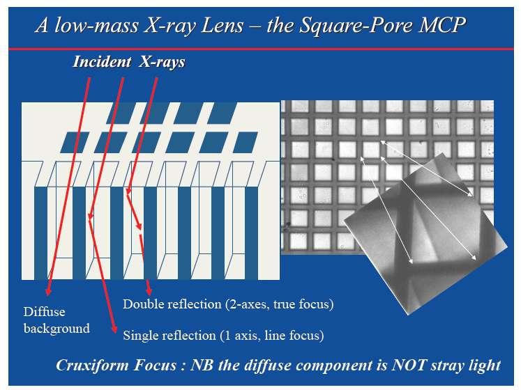
14 14


15 Square Pore MCPs Glass plate - thickness 1-2 mm transmission ~67% Pores d~20 μm, wall~4 μm, L/d~100 K-B stacks 15


16 Pore packing geometries Cartesian packing Lobster Eye - high aperture utilization but correlated single reflection background Random packing inefficient use of aperture Waffle packing -redistribute the single reflection background but retain high aperture utilization No centre of symmetry no preferred axis optimum for wide field imaging Octagonal packing, φ=45 degrees Radial packing, φ=0 degrees With radial packing require tandem plates to approximate Wolter I imaging Optimum for narrow field imaging


17 Plate imperfections: Lobster eye PSF Figure errors and surface roughness of the channel walls 4.5 Å rms Misalignment of the channel axes ± 1 arc mins Channel rotation errors ± 1 degree Channel shear ~1/40 of channel pitch Focal length 500 mm Channel L/D 50 1 st cross-arm zero 2FD/L=20 mm HEW of core ~ 4.8 arc mins FWHM ~ 3 arc mins Focusing gain ~
18 Measured PSF FWHMY = arcmin (depending on plate scale Linearisation) FWHMX = arcmin (depending on plate scale Linearisation)
19 Measured PSF
20 Measured PSF
21 Measured PSF
22 Measured PSF
23 Measured PSF
24 Measured PSF
25 Measured PSF
26 Measured PSF
27 Measured PSF
28 Measured PSF
29 Measured PSF
30 Measured PSF
31 Measured PSF
32 Measured PSF
33 Measured PSF
34 Measured PSF

35 Measured PSF
36 Measured PSF
37 Measured PSF
38 Measured PSF

39 Lobster eye collecting area Total collecting area ~22 cm 2 at 1 kev ~ 30% of area in central focused spot Crab ~93 cts/sec 39


40 10 x Lobster modules Total FOV ~9000 sq degrees 6 degree cant angle of modules 240mm square Lobster optics frames, 500mm focal length Angular resolution ~3 arc mins Collecting area ~9 cm 2 at 1 kev
41 K-B Stack Schmidt Geometry 41

42 K-B Si Pore module Module shown is a Wolter I conical approximation prototype Could easily be constructed in the Kirkpatrick Baez geometry square aperture, side length S number of plates N p =S/P P=760 μm T=150 μm D=610 μm open fraction front+rear 64% Wolter I Si pore module Cosine Research No plate curvature required Plates wedged so point at common centre of curvature All stacks are identical 42
 Collecting area ~100 cm 2, angular resolution ~20 arc seconds Sensitivity 5-50 better than Lobster module F=500 mm Narrow field -")
43 Packing of K-B stacks into an aperture Si stacks suitable for larger instruments Focal length 5 m (needs to be > ~2.5 m) Collecting area ~100 cm 2, angular resolution ~20 arc seconds Sensitivity 5-50 better than Lobster module F=500 mm Narrow field - pointed wide field - survey 43
44 Wide field K-B stack Vignetting at 1 kev Grazing angle 1 degrees slot width mm axial slot length 35 mm FOV 20 degrees diameter Collecting area ~110 cm 2 at 1 kev (~constant over FOV) HEW ~22 arc seconds (constant over FOV) Grasp 3.46 m 2 deg 2 Focusing gain ~13300 Area at 13 cm 2 at 6.5 kev Area vs. energy HEW limited by flat plates can be improved using axially curved plates 44
45 Summary Si pore optics modules with wide rib spacing and spherical join plane (Wolter-Schwartzschild) can provide grasp >= WFXT better than 10 arc sec imaging over 1 degree FOV can be improved by introducing axial curvature Glass square pore MCPs provide ~4 arc min imaging and focusing gain of ~ by 30 degree FOV area ~9 cm 2 at 1 kev Si pore K-B stacks in Schmidt geometry provide 20 degree diameter FOV ~300 deg 2 with ~100 cm 2 at 1 kev and HEW of ~20 arc secs Grasp is 10x WFXT focusing gain A new class of instrument deep wide field imaging faint transient imaging 45
The Hot and Energetic Universe
 The Hot and Energetic Universe An Athena+ supporting paper The Optical Design of the Athena+ Mirror Authors and contributors Richard Willingale, Giovanni Pareschi, Finn Christensen and Jan-Willem den Herder
PROCEEDINGS OF SPIE. Aberrations in square pore microchannel optics used for x-ray lobster eye telescopes
 PROCEEDINGS OF SPIE SPIEDigitalLibrary.org/conference-proceedings-of-spie Aberrations in square pore microchannel optics used for x-ray lobster eye telescopes R. Willingale, J. F. Pearson, A. Martindale,
12.4 Alignment and Manufacturing Tolerances for Segmented Telescopes
 330 Chapter 12 12.4 Alignment and Manufacturing Tolerances for Segmented Telescopes Similar to the JWST, the next-generation large-aperture space telescope for optical and UV astronomy has a segmented
Opti 415/515. Introduction to Optical Systems. Copyright 2009, William P. Kuhn
 Opti 415/515 Introduction to Optical Systems 1 Optical Systems Manipulate light to form an image on a detector. Point source microscope Hubble telescope (NASA) 2 Fundamental System Requirements Application
Understanding Optical Specifications
 Understanding Optical Specifications Optics can be found virtually everywhere, from fiber optic couplings to machine vision imaging devices to cutting-edge biometric iris identification systems. Despite
Chapter 18 Optical Elements
 Chapter 18 Optical Elements GOALS When you have mastered the content of this chapter, you will be able to achieve the following goals: Definitions Define each of the following terms and use it in an operational
Sequential Ray Tracing. Lecture 2
 Sequential Ray Tracing Lecture 2 Sequential Ray Tracing Rays are traced through a pre-defined sequence of surfaces while travelling from the object surface to the image surface. Rays hit each surface once
Design parameters Summary
 634 Entrance pupil diameter 100-m Entrance pupil location Primary mirror Exit pupil location On M6 Focal ratio 6.03 Plate scale 2.924 mm / arc second (on-axis) Total field of view 10 arc minutes (unvignetted)
EE119 Introduction to Optical Engineering Spring 2003 Final Exam. Name:
 EE119 Introduction to Optical Engineering Spring 2003 Final Exam Name: SID: CLOSED BOOK. THREE 8 1/2 X 11 SHEETS OF NOTES, AND SCIENTIFIC POCKET CALCULATOR PERMITTED. TIME ALLOTTED: 180 MINUTES Fundamental
Vladimir Vassiliev UCLA
 Vladimir Vassiliev UCLA Reduce cost of FP instrumentation (small plate scale) Improve imaging quality (angular resolution) Minimize isochronous distortion (energy threshold, +) Increase FoV (sky survey,
erosita mirror calibration:
 erosita mirror calibration: First measurements and future concept PANTER instrument chamber set-up for XMM mirror calibration: 12 m length, 3.5 m diameter: 8m to focal plane instrumentation now: f = 1.6
Computer Generated Holograms for Optical Testing
 Computer Generated Holograms for Optical Testing Dr. Jim Burge Associate Professor Optical Sciences and Astronomy University of Arizona jburge@optics.arizona.edu 520-621-8182 Computer Generated Holograms
Physics 431 Final Exam Examples (3:00-5:00 pm 12/16/2009) TIME ALLOTTED: 120 MINUTES Name: Signature:
 TIME ALLOTTED: 120 MINUTES Name: Signature:") Physics 431 Final Exam Examples (3:00-5:00 pm 12/16/2009) TIME ALLOTTED: 120 MINUTES Name: PID: Signature: CLOSED BOOK. TWO 8 1/2 X 11 SHEET OF NOTES (double sided is allowed), AND SCIENTIFIC POCKET CALCULATOR
Physics 431 Final Exam Examples (3:00-5:00 pm 12/16/2009) TIME ALLOTTED: 120 MINUTES Name: PID: Signature: CLOSED BOOK. TWO 8 1/2 X 11 SHEET OF NOTES (double sided is allowed), AND SCIENTIFIC POCKET CALCULATOR
Optical Engineering 421/521 Sample Questions for Midterm 1
 Optical Engineering 421/521 Sample Questions for Midterm 1 Short answer 1.) Sketch a pechan prism. Name a possible application of this prism., write the mirror matrix for this prism (or any other common
Physics 2306 Fall 1999 Final December 15, 1999
 Physics 2306 Fall 1999 Final December 15, 1999 Name: Student Number #: 1. Write your name and student number on this page. 2. There are 20 problems worth 5 points each. Partial credit may be given if work
3.0 Alignment Equipment and Diagnostic Tools:
 3.0 Alignment Equipment and Diagnostic Tools: Alignment equipment The alignment telescope and its use The laser autostigmatic cube (LACI) interferometer A pin -- and how to find the center of curvature
HRMA Ghost Image Properties
 20.1. Ghost Images Geometry 07 Jul 1999 in progress Chapter 20 HRMA Ghost Image Properties Terrance J. Gaetz 20.1 Ghost Images Geometry Ghost images occur when photons reach the focal plane after missing
Optical Design of an Off-axis Five-mirror-anastigmatic Telescope for Near Infrared Remote Sensing
 Journal of the Optical Society of Korea Vol. 16, No. 4, December 01, pp. 343-348 DOI: http://dx.doi.org/10.3807/josk.01.16.4.343 Optical Design of an Off-axis Five-mirror-anastigmatic Telescope for Near
Lecture 2: Geometrical Optics. Geometrical Approximation. Lenses. Mirrors. Optical Systems. Images and Pupils. Aberrations.
 Lecture 2: Geometrical Optics Outline 1 Geometrical Approximation 2 Lenses 3 Mirrors 4 Optical Systems 5 Images and Pupils 6 Aberrations Christoph U. Keller, Leiden Observatory, keller@strw.leidenuniv.nl
Post PDR Optical Design Study. Robert Barkhouser JHU/IDG January 6, 2014
 ARCTIC Post PDR Optical Design Study Robert Barkhouser JHU/IDG January 6, 2014 1 APO 3.5 m Telescope Model From Joe H. as part of f8v240 imager model. dl Note (1) curved focal surface and (2) limiting
Lecture 2: Geometrical Optics. Geometrical Approximation. Lenses. Mirrors. Optical Systems. Images and Pupils. Aberrations.
 Lecture 2: Geometrical Optics Outline 1 Geometrical Approximation 2 Lenses 3 Mirrors 4 Optical Systems 5 Images and Pupils 6 Aberrations Christoph U. Keller, Leiden Observatory, keller@strw.leidenuniv.nl
Final Reg Optics Review SHORT ANSWER. Write the word or phrase that best completes each statement or answers the question.
 Final Reg Optics Review 1) How far are you from your image when you stand 0.75 m in front of a vertical plane mirror? 1) 2) A object is 12 cm in front of a concave mirror, and the image is 3.0 cm in front
Final Feed Selection Study For the Multi Beam Array System
 National Astronomy and Ionosphere Center Arecibo Observatory Focal Array Memo Series Final Feed Selection Study For the Multi Beam Array System By: Germán Cortés-Medellín CORNELL July/19/2002 U n i v e
Wide Field Imager for Athena
 Exploring the Hot and Energetic Universe: The first scientific conference dedicated to the Athena X-ray observatory Wide Field Imager for Athena Norbert Meidinger on behalf of the WFI proto-consortium
EUV Multilayer Fabrication
 EUV Multilayer Fabrication Rigaku Innovative Technologies Inc. Yuriy Platonov, Michael Kriese, Jim Rodriguez ABSTRACT: In this poster, we review our use of tools & methods such as deposition flux simulation
The optical analysis of the proposed Schmidt camera design.
 The optical analysis of the proposed Schmidt camera design. M. Hrabovsky, M. Palatka, P. Schovanek Joint Laboratory of Optics of Palacky University and Institute of Physics of the Academy of Sciences of
Collimation Tester Instructions
 Description Use shear-plate collimation testers to examine and adjust the collimation of laser light, or to measure the wavefront curvature and divergence/convergence magnitude of large-radius optical
The Wide Field Imager for the Athena X-ray Observatory
 Wide Field Imager The for the Athena X-ray Observatory Arne Rau (Athena/WFI Project Scien:st, MPE - on behalf of the WFI Team) The Hot and Energetic Universe - Science Theme for ESA s L2 Mission How do
Lecture 3: Geometrical Optics 1. Spherical Waves. From Waves to Rays. Lenses. Chromatic Aberrations. Mirrors. Outline
 Lecture 3: Geometrical Optics 1 Outline 1 Spherical Waves 2 From Waves to Rays 3 Lenses 4 Chromatic Aberrations 5 Mirrors Christoph U. Keller, Leiden Observatory, keller@strw.leidenuniv.nl Lecture 3: Geometrical
Steve O Dell
 Optics requirements for the Generation-X x-ray telescope Steve O Dell NASA Marshall Space Flight Center 2008.10.09-11 Authors Smithsonian Astrophysical Observatory (SAO) Roger Brissenden, Dan Schwartz,
Gas Pixel Detectors. Ronaldo Bellazzini INFN - Pisa. 8th International Workshop on Radiation Imaging Detectors (IWORID-8) Pisa 2-6/july 2
 Pisa 2-6/july 2") Gas Pixel Detectors Ronaldo Bellazzini INFN - Pisa 8th International Workshop on Radiation Imaging Detectors (IWORID-8) Pisa 2-6/july 2 2006 Polarimetry: The Missing Piece of the Puzzle Imaging: Chandra
Gas Pixel Detectors Ronaldo Bellazzini INFN - Pisa 8th International Workshop on Radiation Imaging Detectors (IWORID-8) Pisa 2-6/july 2 2006 Polarimetry: The Missing Piece of the Puzzle Imaging: Chandra
Optical design of Dark Matter Telescope: improving manufacturability of telescope
 Optical design of Dark Matter Telescope: improving manufacturability of telescope Lynn G. Seppala November 5, 2001 The attached slides contain some talking point that could be useful during discussions
EE119 Introduction to Optical Engineering Fall 2009 Final Exam. Name:
 EE119 Introduction to Optical Engineering Fall 2009 Final Exam Name: SID: CLOSED BOOK. THREE 8 1/2 X 11 SHEETS OF NOTES, AND SCIENTIFIC POCKET CALCULATOR PERMITTED. TIME ALLOTTED: 180 MINUTES Fundamental
Optical System Design
 Phys 531 Lecture 12 14 October 2004 Optical System Design Last time: Surveyed examples of optical systems Today, discuss system design Lens design = course of its own (not taught by me!) Try to give some
SIMBOL-X. Peter Lechner MPI-HLL Project Review Schloss Ringberg, science background. mission. telescope.
 SIMBOL-X Peter Lechner MPI-HLL Project Review Schloss Ringberg, 24.04.07 science background mission telescope detector payload low energy detector science background science targets black holes astrophysics
OPTICS OF SINGLE BEAM, DUAL BEAM & ARRAY RECEIVERS ON LARGE TELESCOPES J A M E S W L A M B, C A L T E C H
 OPTICS OF SINGLE BEAM, DUAL BEAM & ARRAY RECEIVERS ON LARGE TELESCOPES J A M E S W L A M B, C A L T E C H OUTLINE Antenna optics Aberrations Diffraction Single feeds Types of feed Bandwidth Imaging feeds
PREPARED BY: I. Miller DATE: 2004 May 23 CO-OWNERS REVISED DATE OF ISSUE/CHANGED PAGES
 Page 1 of 34 LIGHTMACHINERY TEST REPORT LQT 30.11-3 TITLE: HMI Michelson Interferometer Test Report Serial Number 3 wide band FSR INSTRUCTION OWNER HMI Project Manager PREPARED BY: I. Miller DATE: 2004
Magnification, stops, mirrors More geometric optics
 Magnification, stops, mirrors More geometric optics D. Craig 2005-02-25 Transverse magnification Refer to figure 5.22. By convention, distances above the optical axis are taken positive, those below, negative.
Novel micro-pore X-ray optics produced with micro-channel plate technology
 Novel micro-pore X-ray optics produced with micro-channel plate technology MW. Beijersbergena, M. Bavdaza, A.Peacocka, E. Tomasellia, G. Fraserb, A. Brunton, G. Priceb, M. Krumreyc,. Herrmann, A. Freund,
PHY 431 Homework Set #5 Due Nov. 20 at the start of class
 PHY 431 Homework Set #5 Due Nov. 0 at the start of class 1) Newton s rings (10%) The radius of curvature of the convex surface of a plano-convex lens is 30 cm. The lens is placed with its convex side down
Using molded chalcogenide glass technology to reduce cost in a compact wide-angle thermal imaging lens
 Using molded chalcogenide glass technology to reduce cost in a compact wide-angle thermal imaging lens George Curatu a, Brent Binkley a, David Tinch a, and Costin Curatu b a LightPath Technologies, 2603
October 7, Peter Cheimets Smithsonian Astrophysical Observatory 60 Garden Street, MS 5 Cambridge, MA Dear Peter:
 October 7, 1997 Peter Cheimets Smithsonian Astrophysical Observatory 60 Garden Street, MS 5 Cambridge, MA 02138 Dear Peter: This is the report on all of the HIREX analysis done to date, with corrections
Mirrors. Plano and Spherical. Mirrors. Published on II-VI Infrared
 Page 1 of 13 Published on II-VI Infrared Plano and Spherical or total reflectors are used in laser cavities as rear reflectors and fold mirrors, and externally as beam benders in beam delivery systems.
Optical Design of the SuMIRe PFS Spectrograph
 Optical Design of the SuMIRe PFS Spectrograph Sandrine Pascal* a, Sébastien Vives a, Robert H. Barkhouser b, James E. Gunn c a Aix Marseille Université - CNRS, LAM (Laboratoire d'astrophysique de Marseille),
Lens Design I. Lecture 5: Advanced handling I Herbert Gross. Summer term
 Lens Design I Lecture 5: Advanced handling I 2018-05-17 Herbert Gross Summer term 2018 www.iap.uni-jena.de 2 Preliminary Schedule - Lens Design I 2018 1 12.04. Basics 2 19.04. Properties of optical systems
PREPARED BY: I. Miller DATE: 2004 May 23 CO-OWNERS REVISED DATE OF ISSUE/CHANGED PAGES
 Page 1 of 30 LIGHTMACHINERY TEST REPORT LQT 30.11-1 TITLE: HMI Michelson Interferometer Test Report Serial Number 1 - Wideband FSR INSTRUCTION OWNER HMI Project Manager PREPARED BY: I. Miller DATE: 2004
RMS roughness: < 1.5Å on plane surfaces and about 2Å on smoothly bended spherical surfaces
 HIGH QUALITY CAF 2 COMPONENTS LOWEST STRAYLIGHT LOSSES IN THE UV Our special polishing technique for calcium fluoride guarantees: RMS roughness: < 1.5Å on plane surfaces and about 2Å on smoothly bended
The Formation of an Aerial Image, part 3
 T h e L i t h o g r a p h y T u t o r (July 1993) The Formation of an Aerial Image, part 3 Chris A. Mack, FINLE Technologies, Austin, Texas In the last two issues, we described how a projection system
PHYS 160 Astronomy. When analyzing light s behavior in a mirror or lens, it is helpful to use a technique called ray tracing.
 Optics Introduction In this lab, we will be exploring several properties of light including diffraction, reflection, geometric optics, and interference. There are two sections to this lab and they may
Chapter Ray and Wave Optics
 109 Chapter Ray and Wave Optics 1. An astronomical telescope has a large aperture to [2002] reduce spherical aberration have high resolution increase span of observation have low dispersion. 2. If two
EUV Plasma Source with IR Power Recycling
 1 EUV Plasma Source with IR Power Recycling Kenneth C. Johnson kjinnovation@earthlink.net 1/6/2016 (first revision) Abstract Laser power requirements for an EUV laser-produced plasma source can be reduced
Lecture 4: Geometrical Optics 2. Optical Systems. Images and Pupils. Rays. Wavefronts. Aberrations. Outline
 Lecture 4: Geometrical Optics 2 Outline 1 Optical Systems 2 Images and Pupils 3 Rays 4 Wavefronts 5 Aberrations Christoph U. Keller, Leiden University, keller@strw.leidenuniv.nl Lecture 4: Geometrical
PREPARED BY: I. Miller DATE: 2004 May 23 CO-OWNERS REVISED DATE OF ISSUE/CHANGED PAGES
 Page 1 of 30 LIGHTMACHINERY TEST REPORT LQT 30.11-2 TITLE: HMI Michelson Interferometer Test Report Serial Number 2 - Narrowband FSR INSTRUCTION OWNER HMI Project Manager PREPARED BY: I. Miller DATE: 2004
Arcsecond and Sub-arcsecond Imaging with Multi Image X-ray Interferometer for (Very) Small Satellites
 Small Satellites") X-ray Universe 2017 @Rome July 09 2017 Arcsecond and Sub-arcsecond Imaging with Multi Image X-ray Interferometer for (Very) Small Satellites K. Hayashida, T. Kawabata, H. Kurubi, H. Nakajima, S. Inoue,
X-ray Universe 2017 @Rome July 09 2017 Arcsecond and Sub-arcsecond Imaging with Multi Image X-ray Interferometer for (Very) Small Satellites K. Hayashida, T. Kawabata, H. Kurubi, H. Nakajima, S. Inoue,
simulations, tests and production
 LIGHT FUNNELS: simulations, tests and production J.A. Aguilar, A. Basili, V. Boccone, A. Christov, M. della Volpe, T. Montaruli, M. Rameez University of Geneva, Switzerland 17/07/2013 alessandro.basili@cern.ch
Astronomy 80 B: Light. Lecture 9: curved mirrors, lenses, aberrations 29 April 2003 Jerry Nelson
 Astronomy 80 B: Light Lecture 9: curved mirrors, lenses, aberrations 29 April 2003 Jerry Nelson Sensitive Countries LLNL field trip 2003 April 29 80B-Light 2 Topics for Today Optical illusion Reflections
Detectors for AXIS. Eric D. Miller Catherine Grant (MIT)
") Detectors for AXIS Eric D. Miller Catherine Grant (MIT) Outline detector technology and capabilities CCD (charge coupled device) APS (active pixel sensor) notional AXIS detector background particle environment
Detectors for AXIS Eric D. Miller Catherine Grant (MIT) Outline detector technology and capabilities CCD (charge coupled device) APS (active pixel sensor) notional AXIS detector background particle environment
Introduction. Geometrical Optics. Milton Katz State University of New York. VfeWorld Scientific New Jersey London Sine Singapore Hong Kong
 Introduction to Geometrical Optics Milton Katz State University of New York VfeWorld Scientific «New Jersey London Sine Singapore Hong Kong TABLE OF CONTENTS PREFACE ACKNOWLEDGMENTS xiii xiv CHAPTER 1:
1.6 Beam Wander vs. Image Jitter
 8 Chapter 1 1.6 Beam Wander vs. Image Jitter It is common at this point to look at beam wander and image jitter and ask what differentiates them. Consider a cooperative optical communication system that
The superconducting microcalorimeters array for the X IFU instrument on board of Athena Luciano Gottardi
 The superconducting microcalorimeters array for the X IFU instrument on board of Athena Luciano Gottardi 13th Pisa meeting on advanced detectors Isola d'elba, Italy, May 24 30, 2015 Advance Telescope for
Optimisation. Lecture 3
 Optimisation Lecture 3 Objectives: Lecture 3 At the end of this lecture you should: 1. Understand the use of Petzval curvature to balance lens components 2. Know how different aberrations depend on field
System/Prescription Data
 System/Prescription Data File : U:\alpi's designs\1.0 Meter\1.0 meter optical design\old Lenses- Design Stuff\LCOGT 1.0meter Telescope Design for UCSB.zmx Title: LCOGT 1.0 Meter Telescope Date : THU NOV
Radial Coupling Method for Orthogonal Concentration within Planar Micro-Optic Solar Collectors
 Radial Coupling Method for Orthogonal Concentration within Planar Micro-Optic Solar Collectors Jason H. Karp, Eric J. Tremblay and Joseph E. Ford Photonics Systems Integration Lab University of California
Geometric optics & aberrations
 Geometric optics & aberrations Department of Astrophysical Sciences University AST 542 http://www.northerneye.co.uk/ Outline Introduction: Optics in astronomy Basics of geometric optics Paraxial approximation
Observational Astronomy
 Observational Astronomy Instruments The telescope- instruments combination forms a tightly coupled system: Telescope = collecting photons and forming an image Instruments = registering and analyzing the
Section 5 ISO Drawings ISO 10110
 Section 5 ISO 10110 Drawings Optical Drawings provide a precise Definition of your optic for fabrication. Standards allow for a common language to be used between you and the optician so there is no confusion
Guide to SPEX Optical Spectrometer
 Guide to SPEX Optical Spectrometer GENERAL DESCRIPTION A spectrometer is a device for analyzing an input light beam into its constituent wavelengths. The SPEX model 1704 spectrometer covers a range from
Exercises Advanced Optical Design Part 5 Solutions
 2014-12-09 Manuel Tessmer M.Tessmer@uni-jena.dee Minyi Zhong minyi.zhong@uni-jena.de Herbert Gross herbert.gross@uni-jena.de Friedrich Schiller University Jena Institute of Applied Physics Albert-Einstein-Str.
Assignment X Light. Reflection and refraction of light. (a) Angle of incidence (b) Angle of reflection (c) principle axis
 Angle of incidence (b) Angle of reflection (c) principle axis") Assignment X Light Reflection of Light: Reflection and refraction of light. 1. What is light and define the duality of light? 2. Write five characteristics of light. 3. Explain the following terms (a)
Assignment X Light Reflection of Light: Reflection and refraction of light. 1. What is light and define the duality of light? 2. Write five characteristics of light. 3. Explain the following terms (a)
A novel tunable diode laser using volume holographic gratings
 A novel tunable diode laser using volume holographic gratings Christophe Moser *, Lawrence Ho and Frank Havermeyer Ondax, Inc. 85 E. Duarte Road, Monrovia, CA 9116, USA ABSTRACT We have developed a self-aligned
Parity and Plane Mirrors. Invert Image flip about a horizontal line. Revert Image flip about a vertical line.
 Optical Systems 37 Parity and Plane Mirrors In addition to bending or folding the light path, reflection from a plane mirror introduces a parity change in the image. Invert Image flip about a horizontal
Hartmut Ehmler, last modified on 24 September 2013
 1 Hartmut Ehmler, last modified on 24 September 2013 Abstract A study of parabolic solar cooker design is carried out in order to develop a simple model for the variation of cooking power with imperfect
The Wide Field Imager
 Athena Kickoff Meeting Garching, 29.January 2014 The Wide Field Imager Norbert Meidinger, Athena WFI project leader WFI Flight Hardware Architecture (1 st Draft) DEPFET APS Concept Active pixel sensor
OPTICAL DESIGN OF A RED SENSITIVE SPECTROGRAPH
 OPTICAL DESIGN OF A RED SENSITIVE SPECTROGRAPH A Senior Scholars Thesis by EMILY CATHERINE MARTIN Submitted to Honors and Undergraduate Research Texas A&M University in partial fulfillment of the requirements
Downloaded from
 QUESTION BANK SCIENCE STD-X PHYSICS REFLECTION & REFRACTION OF LIGHT (REVISION QUESTIONS) VERY SHORT ANSWER TYPE (1 MARK) 1. Out of red and blue lights, for which is the refractive index of glass greater?
Notes on the VPPEM electron optics
 Notes on the VPPEM electron optics Raymond Browning 2/9/2015 We are interested in creating some rules of thumb for designing the VPPEM instrument in terms of the interaction between the field of view at
Typical Interferometer Setups
 ZYGO s Guide to Typical Interferometer Setups Surfaces Windows Lens Systems Distribution in the UK & Ireland www.lambdaphoto.co.uk Contents Surface Flatness 1 Plano Transmitted Wavefront 1 Parallelism
Warren J. Smith Chief Scientist, Consultant Rockwell Collins Optronics Carlsbad, California
 Modern Optical Engineering The Design of Optical Systems Warren J. Smith Chief Scientist, Consultant Rockwell Collins Optronics Carlsbad, California Fourth Edition Me Graw Hill New York Chicago San Francisco
5.0 NEXT-GENERATION INSTRUMENT CONCEPTS
 5.0 NEXT-GENERATION INSTRUMENT CONCEPTS Studies of the potential next-generation earth radiation budget instrument, PERSEPHONE, as described in Chapter 2.0, require the use of a radiative model of the
Tolerances. WikiOptics. WikiOptics
 Tolerances 2014 Optical system design Robert E. Fischer/ Biljana Tadic-Galeb 2 Candidate Tolerances for a reasonable performance lens(p.322) Parameter Tolerance Parameter Tolerance Radius Testplate measurement
Chapter 3 Mirrors. The most common and familiar optical device
 Chapter 3 Mirrors The most common and familiar optical device Outline Plane mirrors Spherical mirrors Graphical image construction Two mirrors; The Cassegrain Telescope Plane mirrors Common household mirrors:
GEOMETRICAL OPTICS Practical 1. Part I. BASIC ELEMENTS AND METHODS FOR CHARACTERIZATION OF OPTICAL SYSTEMS
 GEOMETRICAL OPTICS Practical 1. Part I. BASIC ELEMENTS AND METHODS FOR CHARACTERIZATION OF OPTICAL SYSTEMS Equipment and accessories: an optical bench with a scale, an incandescent lamp, matte, a set of
Silicon Meta-Shell Optics for AXIS: High-Resolution, Light-Weight, and Low-Cost
 Silicon Meta-Shell Optics for AXIS: High-Resolution, Light-Weight, and Low-Cost William W. Zhang NASA Goddard Space Flight Center Next Generation X-ray Optics (NGXO) Team K.D. Allgood 1, M.P. Biskach 1,
Figure 7 Dynamic range expansion of Shack- Hartmann sensor using a spatial-light modulator
 Figure 4 Advantage of having smaller focal spot on CCD with super-fine pixels: Larger focal point compromises the sensitivity, spatial resolution, and accuracy. Figure 1 Typical microlens array for Shack-Hartmann
Practice Problems (Geometrical Optics)
") 1 Practice Problems (Geometrical Optics) 1. A convex glass lens (refractive index = 3/2) has a focal length of 8 cm when placed in air. What is the focal length of the lens when it is immersed in water
1 Practice Problems (Geometrical Optics) 1. A convex glass lens (refractive index = 3/2) has a focal length of 8 cm when placed in air. What is the focal length of the lens when it is immersed in water
Exercise 8: Interference and diffraction
 Physics 223 Name: Exercise 8: Interference and diffraction 1. In a two-slit Young s interference experiment, the aperture (the mask with the two slits) to screen distance is 2.0 m, and a red light of wavelength
R.B.V.R.R. WOMEN S COLLEGE (AUTONOMOUS) Narayanaguda, Hyderabad.
 Narayanaguda, Hyderabad.") R.B.V.R.R. WOMEN S COLLEGE (AUTONOMOUS) Narayanaguda, Hyderabad. DEPARTMENT OF PHYSICS QUESTION BANK FOR SEMESTER III PAPER III OPTICS UNIT I: 1. MATRIX METHODS IN PARAXIAL OPTICS 2. ABERATIONS UNIT II
R.B.V.R.R. WOMEN S COLLEGE (AUTONOMOUS) Narayanaguda, Hyderabad. DEPARTMENT OF PHYSICS QUESTION BANK FOR SEMESTER III PAPER III OPTICS UNIT I: 1. MATRIX METHODS IN PARAXIAL OPTICS 2. ABERATIONS UNIT II
Lens Design I. Lecture 3: Properties of optical systems II Herbert Gross. Summer term
 Lens Design I Lecture 3: Properties of optical systems II 205-04-8 Herbert Gross Summer term 206 www.iap.uni-jena.de 2 Preliminary Schedule 04.04. Basics 2.04. Properties of optical systrems I 3 8.04.
1.1 Singlet. Solution. a) Starting setup: The two radii and the image distance is chosen as variable.
 Starting setup: The two radii and the image distance is chosen as variable.") 1 1.1 Singlet Optimize a single lens with the data λ = 546.07 nm, object in the distance 100 mm from the lens on axis only, focal length f = 45 mm and numerical aperture NA = 0.07 in the object space.
1 1.1 Singlet Optimize a single lens with the data λ = 546.07 nm, object in the distance 100 mm from the lens on axis only, focal length f = 45 mm and numerical aperture NA = 0.07 in the object space.
Algebra Based Physics. Reflection. Slide 1 / 66 Slide 2 / 66. Slide 3 / 66. Slide 4 / 66. Slide 5 / 66. Slide 6 / 66.
 Slide 1 / 66 Slide 2 / 66 lgebra ased Physics Geometric Optics 2015-12-01 www.njctl.org Slide 3 / 66 Slide 4 / 66 Table of ontents lick on the topic to go to that section Reflection Refraction and Snell's
Optics and Telescopes
 Optics and Telescopes Properties of Light Law of Reflection - reflection Angle of Incidence = Angle of Law of Refraction - Light beam is bent towards the normal when passing into a medium of higher Index
Bandpass Edge Dichroic Notch & More
 Edmund Optics BROCHURE Filters COPYRIGHT 217 EDMUND OPTICS, INC. ALL RIGHTS RESERVED 1/17 Bandpass Edge Dichroic Notch & More Contact us for a Stock or Custom Quote Today! USA: +1-856-547-3488 EUROPE:
Optical Design with Zemax
 Optical Design with Zemax Lecture : Correction II 3--9 Herbert Gross Summer term www.iap.uni-jena.de Correction II Preliminary time schedule 6.. Introduction Introduction, Zemax interface, menues, file
Aberrations of a lens
 Aberrations of a lens 1. What are aberrations? A lens made of a uniform glass with spherical surfaces cannot form perfect images. Spherical aberration is a prominent image defect for a point source on
DELHI PUBLIC SCHOOL JALANDHAR. (a) Assignment will be discussed and solved in the Class. ( In Physics Notebook)
 Assignment will be discussed and solved in the Class. ( In Physics Notebook)") DELHI PUBLIC SCHOOL JALANDHAR DELHI REVISION ASSIGNMENT NO. 3 Instructions: SUBJECT: PHYSICS CLASS:10 Previous Year Questions (Miscellaneous ) (a) Assignment will be discussed and solved in the Class.
DELHI PUBLIC SCHOOL JALANDHAR DELHI REVISION ASSIGNMENT NO. 3 Instructions: SUBJECT: PHYSICS CLASS:10 Previous Year Questions (Miscellaneous ) (a) Assignment will be discussed and solved in the Class.
Micro- and Nano-Technology... for Optics
 Micro- and Nano-Technology...... for Optics 3.2 Lithography U.D. Zeitner Fraunhofer Institut für Angewandte Optik und Feinmechanik Jena Printing on Stones Map of Munich Stone Print Contact Printing light
Big League Cryogenics and Vacuum The LHC at CERN
 Big League Cryogenics and Vacuum The LHC at CERN A typical astronomical instrument must maintain about one cubic meter at a pressure of
Reflectors vs. Refractors
 1 Telescope Types - Telescopes collect and concentrate light (which can then be magnified, dispersed as a spectrum, etc). - In the end it is the collecting area that counts. - There are two primary telescope
Active Sensors Unit assembly process for the ATLAS High Granularity Timing Device
 Active Sensors Unit assembly process for the ATLAS High Granularity Timing Device D. Lacour for LPNHE Paris group 1. Introduction: Calice Si-W calorimeter concept 2. Gluing and positioning automated device
Aperture Antennas. Reflectors, horns. High Gain Nearly real input impedance. Huygens Principle
 Antennas 97 Aperture Antennas Reflectors, horns. High Gain Nearly real input impedance Huygens Principle Each point of a wave front is a secondary source of spherical waves. 97 Antennas 98 Equivalence