The first commercial thermal imaging camera was sold in 1965 for high voltage power line inspections, by what would later become FLIR Systems.
|
|
|
- Leonard Bond
- 5 years ago
- Views:
Transcription


1

2
3


4 Introduction The first commercial thermal imaging camera was sold in 1965 for high voltage power line inspections, by what would later become FLIR Systems. Since then thermal imaging technology has evolved. Thermal imaging cameras have become compact systems that look just like a digital video camera or digital photo camera. They are easy to use and generate crisp real-time high-resolution images. One of the sectors that rapidly discovered that thermal imaging can provide valuable information that is practically impossible to capture with any other tool is the building industry. From an exotic technology, thermal imaging cameras have evolved to a widespread tool that is used by numerous building inspectors worldwide. A thermal imaging camera is a unique tool to map the energy loss from a building. This method is quick and the thermal images which the camera produces provide a precise and convincing argumentation. The use of a thermal imaging camera either as a standalone tool or in combination with other methods such as BlowerDoor systems speeds up the work considerably. Thermal imaging pinpoints exactly where the energy losses are without the use of any destructive testing methods. Thermal imaging cameras have strongly evolved over the last 50 years. FLIR Systems has always been a thermal imaging pioneer that brings the most advanced thermal imaging cameras to the market. 4
5
6 Renewable energies The fact that traditional energy sources like coal, gas and oil are scarce has also led to rising prices. Furthermore, awareness has risen that we cannot keep polluting our planet using these fossil fuels. Solar Solar panels can convert the sun s energy into electricity. And into hard cash. To receive maximum returns and high yields for decades however, high quality is key. The solar module, the most important part of a solar system, must be reliable and able to continue producing electricity for years at an end. To ensure good quality during the full lifetime cycle of a solar module, thermal imaging cameras can play an important role. The use of thermal imaging cameras for solar panel evaluation offers several advantages. Anomalies can clearly be seen on a crisp thermal image and - unlike most other methods - thermal cameras can be used to scan installed solar panels during normal operation. As fossil fuel reserves dwindle, the prices for coal and gas rise to new heights and many people look to the sun for a renewable power source. But solar panels are susceptible to wear. Building professionals all over the world therefore use thermal imaging cameras to inspect solar panels installed on rooftops or in solar parks. 6
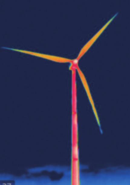
7 Wind Another renewable energy source is wind. All over the world, windmills are becoming increasingly popular for generating electricity. Entire wind parks are being installed both on land and off shore. A windmill contains a lot of mechanical and electrical components that can easily be checked with a thermal imaging camera. Correct maintenance inspections of all parts of a windmill ensure that they will keep generating electricity for many years to come. A thermal image of a wind turbine taken from ground level This booklet is an in-depth guide for building, solar panel and windmill inspections using a thermal imaging camera. There are many details to pay attention to when carrying out a thermal inspection. As well as knowing how the thermal camera works and how to take images, it is important to know the physics behind the thermal patterns of a building, solar panel or windmill, and how they are constructed. All of this has to be taken into consideration to understand, interpret and judge thermal images correctly. It is impossible, however, to cover all principles, concepts and use of systems for analysis of these types of applications in this guidebook. That is why FLIR Systems offers training courses in cooperation with the Infrared Training Center (ITC) specifically designed for building applications. This guidebook will present Thermal imaging applications How the thermal imaging camera works and what to consider when purchasing a camera Comprehensive advice on how to conduct thermographic surveys 7

8 The thermal imaging camera and how it works A thermal imaging camera records the intensity of radiation in the infrared part of the electromagnetic spectrum and converts it to a visible image. Sir William Herschel discovered infrared radiation in What is infrared? Our eyes are detectors that are designed to detect electromagnetic radiation in the visible light spectrum. All other forms of electromagnetic radiation, such as infrared, are invisible to the human eye. The existence of infrared was discovered in 1800 by astronomer Sir Frederick William Herschel. Curious to the thermal difference between different light colors, he directed sunlight through a glass prism to create a spectrum and then measured the temperature of each color. He found that the temperatures of the colors increased from the violet to the red part of the spectrum. After noticing this pattern Herschel decided to measure the temperature just beyond the red portion of the spectrum in a region where no sunlight was visible. To his surprise, he found that this region had the highest temperature of all. 8
9
10
11
12

13 13
14 Using thermal imaging for building applications Inspecting buildings using a thermal imaging camera is a powerful and non invasive means of monitoring and diagnosing the condition of buildings. Thermal imaging technology has become one of the most valuable diagnostic tools for building inspections. A thermal imaging camera can identify problems early, allowing them to be documented and corrected before becoming more serious and more costly to repair. A building diagnostics inspection with a thermal imaging camera can help: Visualize energy losses Detect missing or defective insulation Source air leaks Find moisture in insulation, in roofs and walls, both in the internal and the external structure Detect mold and badly insulated areas Locate thermal bridges Locate water infiltration in flat roofs Detect breaches in hot-water pipes Detect construction failures Monitor the drying of buildings Find faults in supply lines and district heating Detect electrical faults Thermal imaging cameras are the perfect tool for locating and identifying building failures because they make the invisible visible. On a thermal image problems seem to jump right out at you. A thermal imaging camera is the one tool that really lets you SEE it all. A thermal image that includes accurate temperature data provides building experts with important information about the insulation conditions, moisture ingress, mold development, electrical faults, the presence of thermal bridges and the conditions of HVAC systems. Thermal imaging cameras are such a valuable and versatile tool that it is not possible to list all the applications. New and innovative ways of using the technology are being developed every day. Some of the many ways in which thermal imaging cameras can be used within the range of building related applications are explained in this section of the guide. 14
15 Insulation defects and air leaks Thermal imaging is an outstanding tool to locate building defects such as missing insulation, delaminating render and condensation problems. This building is warmer on the inside. It is a sandwich construction, concrete - insulation - concrete. One section of insulation is missing which is not possible to see visually either from the inside or the outside. Here thermal imaging can see what the human eye can t. Framework construction. Many of the sections are missing insulation as indicated by the warmer colors. Glass roof above an atrium. It is watertight, but not air tight. Warm air escapes because of the over pressure.the solution is to air tighten the glass roof. 15
16

17 The thermal image clearly shows insufficient insulation in the wall below the window. Detection of air leaks Air leaks lead to higher energy consumption and often cause problems with the ventilation system. Air leaks can also lead to condensation in the construction which in its turn can cause a poor indoor climate. To detect air leaks with a thermal imaging camera a temperature difference and a pressure difference is needed. With a thermal imaging camera you detect the characteristic patterns that occur when cold air is coming through a leak in the construction, goes along a surface and cools the surface down. The thermal inspection should always take place on the side of the construction with negative pressure. Air leaks are often detected with the help of the pressurization method, often referred to as the "BlowerDoor" test. More information about "BlowerDoor" tests can be found further on in this booklet. Image shows air leaks between the ceiling and the window. 17

18 Moisture Detection Moisture damage is the most common form of deterioration for a building. Air leakage can cause condensation to form within walls, floors, or ceilings. Wet insulation takes a long time to dry and becomes a prime location for mold and fungi. Scanning with a thermal imaging camera can locate moisture that creates an environment conductive to mold. One might smell its presence, but not know where it is forming. A thermal survey will determine where moist areas are located that can lead to serious mold which can lead to health issues. Moisture intrusion in floor, impossible to see with the human eye, but clearly visible on the thermal image. Moisture can be difficult to spot and the trick is to make the construction change temperature. Materials with moisture will then be clearly visible as they change temperature much slower than dry materials. Where other methods only measure the temperature in one spot, thermal imaging cameras can scan an entire area rapidly. 18 Thermal images taken of the same ceiling. In the left image the room temperature has been changed quickly by heating the room which makes the moisture clearly visible on the thermal image.


19


20 Supply lines and district heating In cold climates, pavements and parking areas are sometimes heated. District heating systems distribute heat, often steam, that is generated in a centralized location for residential and commercial heating requirements. A thermographic survey can easily detect defects in pipes or tubes of any underground heating system. A thermal imaging camera can help to identify the exact location of the defect so that repair works can be minimized. Defects in district heating systems can be easily located with a thermal imaging camera. A thermal image, taken from the air, identifies leaks or insulation failure in the district heating system 20


21 Finding water infiltration in flat roofs Thermal imaging is also used to detect water infiltration in flat roofs. Water retains heat longer than the rest of the roofing material and can easily be detected with a thermal imaging camera very late in the evening or at night after the rest of the roof has cooled down. Tremendous savings can be made by repairing wet areas rather than replacing the entire roof. Water infiltration in flat roofs. 21

22 Locating leaks in floor heating Thermal imaging is an easy-to-use tool to find and check pipes and tubes for leaks, even when the water pipes are laid in the floor or under plaster. The heat of the pipes radiates through the surface and the pattern can be easily detected with a thermal imaging camera. The thermal image shows a leak in an underfloor heating system. Underfloor heating problems can easily be detected with a thermal imaging camera. 22
23 Quality assurance Thermal imaging technology is also used for quality assurance and the inspection of new buildings. During construction-drying, thermal images make it possible to determine the progress of the drying procedures so that necessary measures can be taken to speed up the drying process. If this process can be accelerated and it can be proven, with the help of a thermal imaging camera, that the construction is totally dry, the building can be surrendered faster to the client. Building renovations Thermal imaging provides valuable information during the renovation of buildings and monuments. Framework constructions hidden by mineral plaster can become clearly visible in a thermal image. It can then be decided whether exposure of these structures is useful. The detachment of plaster from walls can also be located in a very early stage so that preservation measures can be taken. Thermal imaging makes underlying structures clearly visible. 23

24 Plumbing Thermal imaging is a perfect tool to detect blocked or broken pipes and other plumbing relates issues. Even if the pipes are laid under the floor or inside a wall it can be possible to determine the exact location of the problem by having hot water flowing through the pipes. The heat will radiate and the problem area will become clearly visible on a thermal image. Detect plumbing problems with thermal imaging. HVAC installations Heating, Ventilation and Air-Conditioning (HVAC) systems need to be well maintained. They need to deliver air at the correct humidity and temperature and filter any indoor pollutants. Thermal imaging can help to determine whether HVAC systems are operating properly. When working incorrectly they can cause poor indoor air quality. 24
25 Electrical faults Every building also contains a lot of electrical installations. Thermal imaging can also be used to scan electrical cabinets, fuses, connections, etc. By detecting problems that are invisible to the naked eye the problem can be repaired. If left unchecked, electrical problems can cause high temperatures. Furthermore, sparks can fly which might set the surroundings on fire. For more information about checking electrical systems with a thermal imaging camera, please read the "Thermal imaging guidebook for industrial applications". One of the fuses is overheated, a potential fire risk. 25


26 Thermal physics for building applications In order to interpret the thermal images correctly the operator needs to know how different materials and circumstances influence the temperature readings from the thermal imaging camera. Some of the most important factors influencing the temperature readings are: 1. Thermal conductivity Different materials have different thermal properties. Insulation tends to warm up slowly, while metals tend to warm up quickly. This is called thermal conductivity. Difference in thermal properties in two different materials can lead to large temperature differences in certain situations. 2. Emissivity To read correct temperatures, one important thing needs to be taken into account, and that is a factor known as emissivity. Emissivity is the efficiency with which an object emits infrared radiation. This is highly dependent on material properties. If you look at the thermal image you might think that the gold paint is colder than the mug surface. In reality they have exactly the same temperature, the difference in intensity of infrared radiation is caused by a difference in emissivity. It is extremely important to set the right emissivity in the camera or the temperature measurements will be incorrect. FLIR Systems thermal imaging cameras have predefined emissivity settings for lots of materials, and the rest can be found in an emissivity table. 26
27
28 4. Indoor and outside temperatures To detect missing or ill performing insulation using thermal imaging cameras there needs to be a difference between the temperature indoors and the temperature outside. It is often possible to do work with smaller temperature differences, but usually a temperature difference of at least 10 C between the two sides of the wall is advisable. Such inspections are typically done from both the inside and the outside. Missing, damaged or non-performing insulation will stand out clearly if the temperature difference is sufficient. The user should know the indoor- and outdoor temperature and also needs to know if there have been big temperature changes during the last 24 hours. 5. Influences on the outside of a building It probably goes without saying that direct sunlight can influence thermal readings, but sunlight can have long lasting effects as well. Direct sunlight and shadows might even influence the thermal pattern on a surface many hours after the exposure to sunlight has ended. Differences in thermal conductivity can also cause differences in thermal patterns. Brick changes temperature much slower than wood, for example. Wind can also influence the thermal data. Airflows cool down the surface material, lowering the temperature differences between hot and cold areas. Another obvious factor that can render thermal imaging inspection useless is rain, since it lowers the surface temperatures. Even after the rain has stopped the evaporation of the water cools down the material s surface. Obviously this can lead to misleading thermal patterns. 6. Heating and ventilation systems External influences on surface temperatures can also be found indoors. Ambient temperature can influence the object surface temperature, but there s another factor as well: climate control. Heating systems create temperature differences that can cause misleading thermal patterns. Cool air flowing from ventilators or air conditioning systems can have the opposite effect, cooling down the surface. 28

29 7. Influences on the inside of the building Bookshelves, cabinets and pictures hanging on the wall can also change the thermal pattern. These examples of furniture and wall decorations have an insulating effect. If these things are taken away from the wall, that area of the wall will show up in the thermal image as being colder. This might be confused for missing insulation. For that reason it is advisable to remove items from the wall at least 6 hours before inspection. These two thermal images are taken of the same wall. The temperature outside is colder than inside. The image to the right shows what can happen when you take away a picture from the wall. The cold area behind the picture has the same size as the area between two studs in the wall, it looks like some insulation is missing in the wall. 8. Reflections from the surroundings When scanning reflective targets, be sure to change your angle to minimize the reflections on the image. The reflection could be from your body heat, or some other heat source in the area, a piece of machinery, light bulb or a transformer. Reflections will give you incorrect data in the thermal image, and if not understood, it is a data error. The image shows reflections on an inner wall (to the right) caused by the window to the left. 29

30 9. Type of materials used in the construction Some materials, for example concrete, are thermally slow which mean they change temperature very slowly. Other materials, like most metals, change temperature quickly. In order to interpret the results correctly, the thermographer has to know if there has been any big temperature change outside or inside before the inspection takes place as this can affect the temperature readings. 10. How the construction is built An outer wall can be built with an air gap between the outer skin and the rest of the construction. Such type of construction is not suitable for control from the outside. Any framework in the wall construction becomes colder seen from the inside (provided it s warmer inside). From the cold side it is the opposite situation. These are expected characteristic patterns and there is nothing wrong. Thermal image taken from the inside. The framework is visible, and so are the screws fitting the sheet covering to the framework. The corner is clearly colder, called a corner-effect, but there is nothing wrong here. 30

31 31

32 Thermal imaging cameras for inspecting solar panels. Renewable energies The fact that traditional energy sources like coal, gas and oil are scarce has led to high prices. Furthermore, awareness has risen that we cannot keep polluting our planet using these fossil fuels. With solar panels on your roof you can convert the sun s energy into electricity and into hard cash. Solar power can be a lucrative investment. To receive maximum return and high yields for decades however, high quality is key. The solar module is the most important part of a solar system. It must be reliable and able to continue producing electricity for years at an end. To ensure reliable operation during the full lifetime cycle of a solar module, thermal imaging cameras can play an important role. As fossil fuel reserves dwindle, the prices for coal and gas rise to new heights and many people look to the sun for a renewable power source. But solar panels are susceptible to wear. Building professionals all over the world therefore use thermal imaging cameras to inspect solar panels installed on rooftops or in solar parks. Inspecting solar panels The use of thermal imaging cameras for solar panel evaluation offers several advantages. Anomalies can clearly be seen on a crisp thermal image and - unlike most other methods thermal imaging cameras can be used to scan installed solar panels during normal operation. Finally, thermal imaging cameras also allow to scan large areas within a short time frame. 32
33 With a thermal imaging camera, potential problem areas can be detected and repaired before actual problems or failures occur. But not every thermal imaging camera is suited for solar cell inspection, and there are some rules and guidelines that need to be followed in order to perform efficient inspections and to ensure that you draw correct conclusions. These red spots indicate modules that are consistently hotter than the rest, indicating faulty connections. This hot spot within one solar cell indicates physical damage within the cell. Procedures for inspecting solar panels with thermal imaging cameras To achieve sufficient thermal contrast when inspecting solar cells in the field, a solar irradiance of 500 W/m 2 or higher is needed. For the maximum result a solar irradiance of 700 W/m 2 is advisable. The solar irradiance describes the instantaneous power incident on a surface in units of kw/m 2, which can be measured with either a pyranometer (for global solar irradiance) or a pyrheliometer (for direct solar irradiance). It strongly depends on location and local weather. Low outside temperatures may also increase thermal contrast. This thermal image shows an example of the so-called patchwork pattern, which indicates that this panel has a defective bypass diode. This thermal image shows a hot spot due to cell breakage in a standard 60 cell module. 33
34 What type of camera do you need? Handheld thermal imaging cameras for building inspections typically have an uncooled micro bolo meter detector sensitive in the 8 14 μm waveband. However, glass is not transparent in this region. When solar cells are inspected from the front, a thermal imaging camera sees the heat distribution on the glass surface but only indirectly the heat distribution in the underlying cells. Therefore, the temperature differences that can be measured and seen on the solar panel s glass surface are small. In order for these differences to be visible, the thermal imaging camera used for these inspections needs a thermal sensitivity 0.08 ºC. To clearly visualize small temperature differences in the thermal image, the camera should also allow manual adjustment of the level and span. Thermal image with level and span in automatic mode (left) and manual mode (right). Photovoltaic modules are generally mounted on highly reflective aluminum framework, which shows up as a cold area on the thermal image, because it reflects the thermal radiation emitted by the sky. In practice that means that the thermal imaging camera will display the framework temperature as being well below 0 C. Because the thermal imaging camera's display algorithm automatically adapts to the maximum and minimum measured temperatures, many small thermal anomalies will not immediately be visible. To achieve a high contrast thermal image continuous manual correction of level and span would be needed. 34
35

36 Viewing angle recommended (green) and to be avoided (red) during thermographic inspections. In order to avoid reflection of the thermal imaging camera and the operator in the glass, it should not be positioned perpendicularly to the module being inspected. However, emissivity is at its highest when the camera is perpendicular, and decreases with an increasing angle. A viewing angle of 5 60 is a good compromise (where 0 is perpendicular). Long distance observations It is not always easy to achieve a suitable viewing angle during the measurement set-up. Using a tripod can provide a solution in most cases. In more difficult conditions it might be necessary to use mobile working platforms or even to fly over the solar cells with a helicopter. In these cases, the longer distance from the target can be advantageous, since a larger area can be seen in one pass. To ensure the quality of the thermal image, a thermal imaging camera with an image resolution of at least pixels, preferably pixels, should be used for these longer distances. Faulty solar cells produce an excess of heat, making them easy to spot with thermal imaging technology. 36
37 The camera should also have an interchangeable lens, so the operator can switch to a telephoto lens for long distance observations, such as from a helicopter. It is advisable, however, to only use telephoto lenses with thermal imaging cameras that have a high image resolution. Low resolution thermal imaging cameras will be unable to pick up the small thermal details that indicate solar panel faults in long distance measurements using a telephoto lens. Looking at it from a different perspective In most cases installed photovoltaic modules can also be inspected with a thermal imaging camera from the rear of a module. This method minimizes interfering reflections from the sun and the clouds. In addition, the temperatures obtained at the back may be higher, as the cell is being measured directly and not through the glass surface. The hot spots on this thermal image taken from the front of the solar panel might seem to indicate that a multitude of cells are working inefficiently. Inspection from the back shows no hot spots, the hot spots in the previous thermal image taken from the front were caused by cloud reflection. 37
38 Ambient and measurement conditions When undertaking thermographic inspections, the sky should be clear since clouds reduce solar irradiance and also produce interference through reflections. Informative images can, however, be obtained even with an overcast sky, provided that the thermal imaging camera used is sufficiently sensitive. Calm conditions are desirable, since any airflow on the surface of the solar module will cause convective cooling and thus will reduce the thermal gradient. The cooler the air temperature, the higher the potential thermal contrast. Performing thermographic inspections in the early morning is an option. Two strings of cells show up hot in the thermal image, which indicates broken bypass diodes. This thermal image shows large areas with elevated temperatures. Without more information, it is not obvious whether these are thermal anomalies or shadowing/reflections. Another way to enhance thermal contrast is to disconnect the cells from the load, to prevent the flow of current, which allows heating to occur through solar irradiance alone. The load is then connected, and the cells are observed in the heating phase. Under normal circumstances, however, the system should be inspected under standard operating conditions, namely under load. Depending on the type of cell and the kind of fault or failure, measurements under no-load or short-circuit conditions can provide additional information. With a thermal imaging camera you can quickly locate issues such as this damaged cell, so the problem can be solved promptly. 38
39 Measurement errors Measurement errors arise primarily due to poor camera positioning and suboptimal ambient and measurement conditions. Typical measurement errors are caused by: too shallow viewing angle change in solar irradiance over time (due to changes in sky cover, for example) reflections (e.g., sun, clouds, surrounding buil dings of greater height, measurement set-ups) partial shadowing (e.g., due to surrounding buildings or other structures). What can you see in the thermal image If parts of the solar panel are hotter than others, the warm areas will show up clearly in the thermal image. Depending on the shape and location, these hot spots and areas can indicate several different faults. If an entire module is warmer than usual that might indicate interconnection problems. If individual cells or strings of cells are showing up as a hot spot or a warmer patchwork pattern, the cause can usually be found either in defective bypass diodes, in internal short-circuits, or in a cell mismatch. A test with a solar panel shows that the hot spots can quite easily be seen on the thermal image, even from the front. Shadowing and cracks in cells show up as hot spots or polygonal patches in the thermal image. The temperature rise of a cell or of part of a cell indicates a defective cell or shadowing. Thermal images obtained under load, no-load, and short-circuit conditions should be compared. A comparison of thermal images of the front and rear faces of the module can also give valuable information. Of course, for correct identification of the failure, modules showing anomalies must also be tested electrically and inspected visually. 39
40 Conclusions The thermographic inspection of photovoltaic systems allows the fast localization of potential defects at the cell and module level as well as the detection of possible electrical interconnection problems. The inspections are carried out under normal operating conditions and do not require a system shut down. For correct and informative thermal images, certain conditions and measurement procedures should be observed: a suitable thermal imaging camera with the right accessories should be used; sufficient solar irradiance is required (at least 500 W/m 2 above 700 W/m 2 preferred); the viewing angle must be within the safe margins (between 5 and 60 ); shadowing and reflections must be prevented. Thermal imaging cameras are primarily used to locate defects. Classification and assessment of the anomalies detected require a sound understanding of solar technology, knowledge of the system inspected, and additional electrical measurements. Proper documentation is, of course, a must, and should contain all inspection conditions, additional measurements, and other relevant information. Inspections with a thermal imaging camera - starting with the quality control in the installation phase, followed by regular checkups - facilitate complete and simple system condition monitoring. This will help to maintain the solar panels' functionality and to extend their lifetime. Using thermal imaging cameras for solar panel inspections will therefore drastically improve the operating company s return on investment. Images taken from the back of a solar panel show much less reflection than the front, making the temperature measurements much more accurate. 40

 Faulty interconnections Cracks Cracks in cells Pollution Bird droppings")
41 In order not to draw false conclusions you need to hold the thermal imaging camera under a correct angle when inspecting solar panels. Thermal image made using a FLIR P660 camera on a flight over a solar farm. (Thermogram courtesy of Evi Müllers, IMM) Error type Example Appears in the thermal image as Manufacturing defect Impurities and gas pockets Cracks in cells A hot spot or cold spot Cell heating, form mainly elongated Damage Temporary shadowing Defective bypass diode (causes short circuits and reduces circuit protection) Faulty interconnections Cracks Cracks in cells Pollution Bird droppings Humidity N.a. Module or string of modules not connected Cell heating, form mainly elongated A portion of a cell appears hotter Hot spots A patchwork pattern A module or a string of modules is consistently hotter Table 1: List of typical module errors (Source: ZAE Bayern e.v, Überprüfung der Qualität von Photovoltaik-Modulen mittels Infrarot-Aufnahmen ["Quality testing in photovoltaic modules using infrared imaging ], 2007) 41


42 But thermal imaging cameras can do much more than solar panel inspections alone. They are also very usefull for the maintenance of the entire electrical circuit, including connectors, cables, inverters, etc. This inverter converts the direct current from the solar panels to alternating current. Thermal imaging cameras can be used to inspect this equipment. An external Extech clamp meter can provide additional information. FLIR thermal imaging cameras are used to inspect the entire solar installation, including cables, connectors, fuse boxes and inverters, in other words: the entire system. FLIR thermal imaging cameras can also be used to scan the other components of the solar installation, such as this faulty connector. 42
43 43


44 Inspecting wind turbines with thermal imaging cameras Energy harvested from the wind through wind turbines is one of the most common forms of renewable energy. To that end new wind turbines are installed every year all over Europe and all over the world. All of these wind turbines have to be monitored and maintained. FLIR thermal imaging cameras can play an important role in the wind turbine predictive maintenance programs. Thermal imaging cameras from FLIR systems are used to inspect electrical and mechanical installations all over the world. The thermal data gathered help to prevent dangerous accidents and costly downtime. All critical components of a wind turbine can be monitored using a thermal imaging camera from FLIR Systems. A thermal image of a wind turbine taken from ground level 44
45

46 Inspections with thermal imaging cameras can help prevent such accidents. Both for electrical and mechanical components the general rule is that a component will become hot before it fails. Thermal imaging cameras can be used to spot this rise in temperature before a failure occurs. These hot spots will show up clearly in the thermal image. Thermal imaging helps you see the problem. Where other technologies tell you whether there is a problem with the entire machine, thermal imaging cameras will show you exactly which component is causing the problem. Reliable, quick and efficient: thermal imaging can be used to spot signs of wear on bearings, shafts, gears and brakes, allowing you to repair or replace components before failures occur. Check the entire system Thermal imaging cameras can be used to inspect the electrical components such as transformers, connectors, controllers yaw motors and such. Thermal imaging is the only technology that allows you to inspect all electrical and mechanical components of the wind turbine and of the surrounding electrical system. FLIR thermal imaging camera: the perfect tool Wind turbine maintenance crews all over the world rely on thermal imaging cameras. An important factor in usability in the field is the camera design. All FLIR cameras are as compact as possible, ergonomically designed and easy to use, which is very important if you have to climb tens of meters to get to the wind turbine you are to inspect. Source: Paul Anderson (CC SA 2.0) This huge 12 ton gearbox and disk brake assembly is lifted with a crane to a height of 60 meters to be mounted in this wind turbine nacelle. 46
47 A thermal imaging wind turbine transmission survey. This survey was performed at a height of around 50 meters. Source: CZ Energy Solutions Source: CZ Energy Solutions Source: CZ Energy Solutions Source: CZ Energy Solutions Thermal imaging cameras can be used to scan the entire system surrounding the wind turbines as well. One of these three phase connectors, the rightmost one, is much warmer than the rest. This defect was spotted and was repaired before a failure occurred. Another important factor is the lens. FLIR Systems offers optional 45 and 90 wide angle lenses. This allows you to capture large pieces of equipment in one go, even when you re up close. The fact that you can t take a step back when you re up high inspecting a wind turbine makes this a very important feature. FLIR Systems offers a full range of thermal imaging cameras for building inspections. From the compact entrance model i3, through the practical Ebx- and B-Series to the advanced B660, FLIR Systems has exactly the right type of camera for each application. 47
48 Choosing the right thermal imaging camera supplier Buying a thermal imaging camera is a long term investment. You therefore not only need to select the thermal imaging camera that best fits your needs but also a reliable supplier that can support you over a longer period of time. A well established brand should be able to offer you: Hardware Different users have different needs. It is therefore very important that the manufacturer can offer you a full range of thermal imaging cameras, from affordable entry models to advanced high end models, so that you can choose the one that best fits your needs. Software Whatever your application, you will need software to analyze the thermal images and to report your finding to customers or management. Choose a thermal imaging camera that can be combined with the correct software for your application. Accessories Once you start using a thermal imaging camera and discover all the advantages it has to offer, your needs might change. Make sure you have a system that can grow with your needs. The manufacturer should be able to offer you different types of lenses, displays, etc. Service Although most thermal imaging cameras that are used for building applications are as good as maintenance free, you want to be sure that you have a service center close by in case anything should happen with the camera. Thermal imaging cameras also need to be recalibrated once in a while. In both cases you do not want to send your camera to the other end of the world but to a local repair center to ensure that you have the camera back in the shortest possible timeframe. Training There is more to the world of thermal imaging than just knowing how to handle the camera. Select a supplier that can give you good training and application support when needed. 48

49 49


50 Finding the best solution Basically six key requirements are important to evaluate when investigating a suitable combination of thermal imaging camera, software and training: 1. Image quality 2. Thermal sensitivity 3. Accuracy 4. Camera functions 5. Software 6. Training demands 1. Image quality Image quality or camera resolution is an important factor. The most affordable entry models have a resolution of 60 x 60 pixels, while the advanced high end models have a resolution of 640 x 480 pixels. The thermal imaging cameras with a 320 x 240 or 640 x 480 pixels resolution deliver superior image quality. For more advanced inspections the 640 x 480 pixels resolution is becoming the standard for professional thermographers. A camera with 640 x 480 pixels has 307,200 measurement points in one image which is four times more than a camera with 320 x 240 pixels and 76,800 measurement points. Not only will the measurement accuracy be better, but there is also a huge difference in the image quality. High resolution helps to see, measure and understand more accurately. Thermal image: 640 x 480 pixels Thermal image: 180 x 180 pixels 50

51 High resolution cameras also resolve small details during long distance observations. Compared to a camera with lower image quality you can view a larger area at once without loosing thermal information. With a 640 x 480 pixels camera equipped with at 45 degree lens, an area of about 4 m x 3 m can be inspected at 5 meters distance with only one image. To inspect the same installation with a 320 x 240 pixels camera, also with a 45 degree lens, four images on half the distance are required. Not only does this increase the efficiency in the field, a lower amount of images taken in the field also saves time in the documentation phase. 160x120 pixels 320 x 240 pixels 640 x 480 pixels 640 x 480 pixels One thermal image needed 320 x 240 pixels Four thermal images needed at half the distance 51
52
53 4. Camera functions Emissivity and reflected apparent temperature The emissivity of the object is a very important parameter that has to be taken into account. All FLIR thermal imaging cameras for building applications allow the operator to set the emissivity and reflected apparent temperature. Being able to set the parameters emissivity and reflected apparent temperature makes a huge difference. When buying a thermal imaging camera you should make sure that these functions are included. This thermal image quite clearly shows that reflection can pose a problem. The thermal camera displays the thermal image including the reflections caused by the cloud. When measuring on the reflection the temperature will read as a mixture of the panel temperature and the apparent reflected temperature of the cloud. Manual level and span correction Another important camera feature is the option to manually set the span and level of the displayed thermal images. Without this feature, the camera will automatically display all temperatures between the minimum and maximum temperature of the scene. But sometimes the operator is only interested in a small part of that temperature scale. The span of auto-adjusted thermal image on the left is too wide. The manually tuned thermal image on the right clearly shows heat leakage that was almost invisible in the auto-adjusted thermal image. 53
54 Dewpoint, relative humidity and insulation alarm - Dewpoint alarm: The dewpoint can be regarded as the temperature at which the humidity in a certain volume of air will condense as liquid water. At this point the relative humidity is 100%. By setting a number of parameters inside the camera the dewpoint alarm will automatically detect areas where this can happen due to deficiencies in the building structure. - Relative humidity alarm: In some situations mold will grow on areas where the relative humidity is less than 100%. To detect those areas, the dewpoint alarm can not be used since it only detects areas where the relative humidity is 100%. To detect areas where the relative humidity is less than 100% the relative humidity alarm can be used. You can set the relative humidity above which the alarm will trigger. - Insulation alarm: The insulation alarm detects areas where there may be an insulation deficiency in the building. It triggers when the insulation level falls below a preset value of the energy leakage through the wall. The relative humidity alarm alerts you to the areas where there is a risk of condensation. In this image the area at risk is indicated as blue color. The insulation alarm shows where the areas below or above a set temperature are by making them appear in a different color. 54
55 Digital camera Sometimes it can be very difficult to see what components are shown in a thermal image. In such cases it can help a great deal if you also take a visible light picture of the subject. Most of FLIR s thermal imaging cameras have a built in digital camera. Most building professionals that use thermal imaging cameras claim that they always take a visible light picture as well, to make sure that they know what is shown in the thermal image. Thermal image Visual image LED lights Having a light in your camera ensures that the built in digital visual light camera will be able to produce the clear pictures you need to make the most of the Picture-in-Picture and Thermal Fusion features, regardless of the lighting conditions. Picture-in-Picture With the Picture-in-Picture feature the operator can combine the images from the digital camera and the thermal imaging camera. The combined image will show a frame on top of the digital photo with a portion of the thermal image in it that can be moved around and resized. This helps the operator to better locate problems. This case of water damage clearly shows the advantage of the Picture-in- Picture feature, since the client can quite easily see where this thermal image is located, while this would be more difficult with only the thermal image. 55
56 Thermal Fusion This allows the operator to smoothly combine the two images by setting temperature parameters within which thermal data is shown and outside which the digital photo is shown. This helps to isolate problems and to enable more efficient repairs. Visual image Thermal image Thermal Fusion image Laser pointer Some thermal imaging cameras have a built in laser pointer. There are several reasons why this is an important asset. The laser pointer allows you to see precisely where the thermal imaging camera s lens is focused. With one simple push of a button the laser position will allow you to see exactly where the thermal imaging camera is pointed at so you can identify the measuring target without any guesswork. Another reason is safety. The laser pointer eliminates the tendency to finger-point at objects, which can be dangerous in certain settings. Interchangeable lenses Once you start using a thermal imaging camera and discover all its possibilities your needs might change. Interchangeable lenses can help you to adapt your thermal imaging camera to every situation. For many situations the standard lens might be a good solution but sometimes you simply need a different field of view. In some cases there is not enough room to step back and see the whole picture. A wide angle lens can be the perfect solution. With a wide angle lens the operator can inspect an entire house from just a couple of meters distance. These lenses allow building inspectors to survey an entire building from just several meters away. When the target in question is a bit farther away it may be useful to use a telephoto lens. They are ideal for small or distant targets. 56
57

58


59

60

61
62 How to carry out thermal inspections So the thermal imaging camera has been delivered and the inspecting can begin. But where do you start? In this section of the guidebook some thermal imaging methods will be present in order to get you going. 1. Define the task Start the assignment by interviewing the client about the conditions of the building. For instance: has there been a recent increase in energy usage? Is it cold inside? Is there a noticeable draft? Then determine both the inside and outside temperature and make sure that the temperature difference is sufficient for building inspections (a difference of at least 10 C is advisable). 2. Start from the outside Start the thermographic inspection from the outside. Missing insulation or cold bridges can quickly be located from here. It is important to also take thermal images from areas where conditions seem to be ok. It will allow comparing the result with images that show faults, to evaluate the extent of the different problems found. 3. Continue inside The next step is looking at the situation from the inside. This requires thorough preparation, however. To prepare for the interior thermal scan, the inspector should take steps to ensure an accurate result. This may include moving furniture away from exterior walls and removing drapes. It is advisable to do so at least six hours before the inspection, so the insulating properties of furniture no longer influence the thermal readings from the thermal imaging camera. As stated previously, the requirement for accurate thermographic inspections is a large temperature difference (at least 10 C) between the inside and outside air temperatures. When these conditions are met the inspector can start scanning every room in the building with the thermal imaging camera. In doing so the inspector should make sure that he takes accurate notes of where each thermal image was taken, perhaps by marking the location with arrows on a floor plan to show exactly from which angle the thermal images have been taken. 62


63 4. Set up an air tightness test Small cracks and crevices can cause a draft. This is not only annoying, it can also cause severe energy loss. Air leakage can account for up to half of the energy consumed for heating purposes. An air thightness test, often referred to as a BlowerDoor test can make the smallest cracks visible. The 'BlowerDoor' helps exaggerate air leaking through defects in the building shell. A 'BlowerDoor'system includes three components: a calibrated fan, a door panel system, and a device to measure fan flow and building pressure. The 'BlowerDoor' fan is temporarily sealed into an exterior doorway using the door panel system. The fan is used to blow air into or out of the building, which creates a small pressure difference between inside and outside. The 'BlowerDoor' equipment is normally installed in the entrance door. 63

64 A BlowerDoor system employs a fan to either suck air out of the room or blow air into it, causing a pressure difference. In situations where the outside air is colder, the most common method is to suck air out of the room using the BlowerDoor. As a result the pressure inside the room is lower than the outside air pressure; usually the difference is about 50 Pascal. Due to this pressure difference the outside air will rush into the room through the cracks that are present. The outside air will cool down the location where a crack is present. This temperature difference will clearly show up in the thermal image as a cold spot or cold area, allowing the operator to accurately locate and map the air infiltration pathway. 5. Analysis and Reporting When all rooms have been inspected it is time to return to the office to do the analysis of the images and to summarize the findings in a report. FLIR proprietary software programs such as FLIR Tools, BuildIR and Microsoft Word compatible Reporter allow the inspector to quickly and efficiently draw up a comprehensive building inspection reports to show to colleagues or clients. 64
65
66

67 FULL PRODUCT WARRANTY* DETECTOR WARRANTY* * After product registration on
THERMAL IMAGING GUIDEBOOK FOR BUILDING AND RENEWABLE ENERGY APPLICATIONS
 THERMAL IMAGING GUIDEBOOK FOR BUILDING AND RENEWABLE ENERGY APPLICATIONS An informative guide for the use of thermal imaging cameras for inspecting buildings, solar panels and windmills. Content 1. The
NEWS. FLIR Systems launches FLIR i3 and FLIR E-Series MAINTENANCE. NEW FLIR i3 995 excl.vat. NEW FLIR E-Series.
 MAINTENANCE NEWS New FLIR i3 First thermal imaging camera for less than 1,000 FLIR launches FLIR E-Series NEW FLIR i3 995 excl.vat Thermal imaging helps the Berlin Water Company to provide a continuous
Thermal imaging cameras for Building Inspections
 Thermal imaging cameras for Building Inspections Building inspections Insulation Energy loss Plumbing and piping FLIR Systems: the world leader for thermal imaging cameras FLIR Systems is the world leader
Welcome to TruTech Training!
 Welcome to TruTech Training! We ll be starting in just a few moments www.trutechtools.com 888-224-3437 Making measurement science work! If you are having trouble connecting, please email: Bill@TruTechTools.com
Insulator Testers Frequently Asked Questions. September Version: 1.1
 Insulator Testers Frequently Asked Questions September 2017 Version: 1.1 1 FAQ Contents Page Q1: When is it not safe to work on power lines?... 3 Q2: What is the tolerance of the Positron Insulator Tester
What professionals look for in an infrared camera
 240 px 320 px What professionals look for in an infrared camera Infrared thermography gives troubleshooting and maintenance technicians the tools they need to detect subtle problems before they result
So advanced, we had to create a new category
 Meet the VT02 Visual IR Thermometer So advanced, we had to create a new category A troubleshooting camera with an infrared heat map. See beyond temperature The new VT02 Visual IR Thermometer bridges the
Fluke 570 Series Infrared Thermometers:
 Fluke 570 Series Infrared Thermometers: Adding more precision to non-contact temperature measurement Application Note 572 574 This application note describes the Fluke 570 Series, the most advanced infrared
MICROSCANNER TM D-Series
 MICROSCANNER TM D-Series High Performance Models I N S T R U C T I O N M A N U A L C O R P O R A T I O N 818098 400 Pleasant Street Watertown, MA 02472 (617) 923-9900 800-442-3006 FAX: 617-923-9911 C O
Sensor Troubleshooting Application Note
 Sensor Troubleshooting Application Note Rev. May 2008 Sensor Troubleshooting Application Note 2008 Argus Control Systems Limited. All Rights Reserved. This publication may not be duplicated in whole or
TEMPERATURE MEASUREMENT SPECIALISTS
 TEMPERATURE MEASUREMENT SPECIALISTS 0845 053 3145 www.processparameters.co.uk Industrial Temperature Solutions After time, temperature is the most frequently measured parameter. It affects every aspect
Testo SuperResolution the patent-pending technology for high-resolution thermal images
 Professional article background article Testo SuperResolution the patent-pending technology for high-resolution thermal images Abstract In many industrial or trade applications, it is necessary to reliably
Key Elements for Better Infrared Thermography
 Key Elements for Better Infrared Thermography R. James Seffrin, Director Infraspection Institute 425 Ellis Street Burlington, NJ 08016 609-239-4788 www.infraspection.com Abstract Successful thermography
The 7 secrets to better infrared image quality
 Leading the field in feature innovation Fluke has more experience than most infrared providers. Our design team has been on the job and in the field for thousands of hours with our thermography customers.
Example Report Ref: 5642 REPORT. Snagging Survey/ Investigation and Report
 Example Report Ref: 5642 Example Report Date: xx/xx/xxxx Example Report Example Report REPORT Snagging Survey/ Investigation and Report Client: xxxx xxxxxx Site Location: Address Address Address Address
See more with the thermal imager testo 880
 Committing to the future See more with the thermal imager testo 880 Now with: Auto Hot/Cold Spot Recognition and new pro software TO SEE MORE... Infrared radiation cannot be perceived by the human eye.
Fluke TiR Series Thermal Imagers
 Fluke TiR 2 Specs Provided by www.aaatesters.com Fluke TiR Series s Locate building problems quickly and easily. Largest, sharpest thermal images Best sensitivity Fusion of thermal and visual images Innovative
FLASH LiDAR KEY BENEFITS
 In 2013, 1.2 million people died in vehicle accidents. That is one death every 25 seconds. Some of these lives could have been saved with vehicles that have a better understanding of the world around them
Building thermography.
 Building thermography. Simply see more with the thermal imagers from Testo. Building thermography Simply see more without contact. Testo thermal imagers detect anomalies and damage to building shells or
Application Note. Detection of Partial Discharge Using Ultrasound. Detection of Partial Discharge Using Ultrasound. Problem. iriss.
 Detection of Partial Discharge Using Ultrasound Problem In electrical systems, especially above 1,000 Volts, sufficient and properly maintained equipment insulation helps ensure equipment longevity. However,
Secure your solar investment. inside. 1OO % transparency = 1OO % performance.
 Secure your solar investment inside 1OO % transparency = 1OO % performance www.sunsniffer.de www.sunsniffer.de page 2 Why 1OO % transparency? With a solar energy system, anybody can produce environmentally
IGBT Induction Heater Profiles
 IGBT Induction Heater Profiles United Induction Heating Machine Limited UIHM is experienced in Induction Heating Machine and Induction Heating Power Supply,induction heating equipments can be used in induction
5 FACTORS INFLUENCING RADIOMETRIC TEMPERATURE MEASUREMENTS
 5 FACTORS INFLUENCING RADIOMETRIC TEMPERATURE MEASUREMENTS CONTENTS Page Introduction 2 1. Radiometry and Surface Characteristics 3 2. Emissivity 4 3. Reflectivity 5 4. Effects of Atmosphere 6 5. Resolution
The Importance of Spatial Resolution in Infrared Thermography Temperature Measurement Three Brief Case Studies
 The Importance of Spatial Resolution in Infrared Thermography Temperature Measurement Three Brief Case Studies Dr. Robert Madding, Director, Infrared Training Center Ed Kochanek, Presenter FLIR Systems,
MAC-AFRIC USER S MANUAL MODEL: D.C.INVERTER WELDER 160/200 AMP
 MAC-AFRIC USER S MANUAL MODEL: D.C.INVERTER WELDER 160/200 AMP Safety precautions! The processes of welding and cutting, involve potential hazards, so please take the necessary precautions when performing
Camera Setup and Field Recommendations
 Camera Setup and Field Recommendations Disclaimers and Legal Information Copyright 2011 Aimetis Inc. All rights reserved. This guide is for informational purposes only. AIMETIS MAKES NO WARRANTIES, EXPRESS,
Basic Principles and Operation of Transformer
 Basic Principles and Operation of Transformer CONSTRUCTIONAL ASPECTS Cores In order to enhance core s magnetic properties, it is constructed from an iron and silicon mixture (alloy). The magnetic core
Stop Guessing, Start Seeing
 Measurement Technology Stop Guessing, Start Seeing Temperature guns versus thermal imaging technology Joachim Sarfels and Frank Liebelt In industrial applications, thermal imaging cameras are used for
Agenda. Interior Painting Exterior Painting Typical Problems Low VOC Paints
 Painting 101 Agenda Interior Painting Exterior Painting Typical Problems Low VOC Paints Interior Painting Flat Requires less prep (spot patch & prime) Less durable Eggshell More durable than flat Requires
Infrared Survey Report
 Infrared Survey Report Home of: Mr. and Mrs. Sample Client 926 Main Street Your Town, USA 12345 Prepared by: Qualified Contractor Your Town, USA info@energyscanir.com Toll-Free 888-SCAN 4 IR (888-722-6447)
Model LS 250 Loop Scanner Operator s Manual. Version
 Model LS 250 Loop Scanner Operator s Manual Version 05-2011 Contents 1. Introduction...2 2. Description...3 2.1 Model Nomenclature...3 2.2 Operating Principle...3 2.3 Specifications...5 3. Location and
12 Things to Consider Before Buying an Infrared Camera
 12 12 Things to Consider Before Buying an Infrared Camera A Guide for Investing in Infrared Twelve Things to Consider Before Buying an Infrared Camera Buying an infrared camera is a big commitment. Even
Rabbit Series Laser Engraving Machine HX3040. User s Manual. 1 Jinan King Rabbit Technology Development Co. Ltd.
 Rabbit Laser Engraving Machine HX3040 User s Manual 1 Preface Thank you for buying our Rabbit Series HX3040 Laser Engraving Machine. You will find it has many nice features including easy operation, high
User instructions Compound laboratory microscope
 KERN & Sohn GmbH Ziegelei 1 D-72336 Balingen E-mail: info@kern-sohn.com User instructions Compound laboratory microscope Tel: +49-[0]7433-9933-0 Fax: +49-[0]7433-9933-149 Internet: www.kern-sohn.com KERN
IR WINDOW TRANSMISSION GUIDEBOOK. Copyright CorDEX Instruments Ltd. ID 4015 Rev A
 IR WINDOW TRANSMISSION GUIDEBOOK ID 4015 Rev A Content 1. General... Page 3 2. Introduction... Page 4 3. Aims... Page 5 4. What is Infrared Transmission?... Page 7 5. Infrared 101 - R+A+T=1... Page 8 6.
FIRST FIRING INSTRUCTIONS FOR L&L KILNS WITH A DYNATROL
 WHEN TO DO A FIRST TEST FIRING? Once your kiln is set up, leveled properly (very important), control panel hooked up to the kiln correctly and all the power wired properly, you are ready for your first
FLIR thermal imaging cameras for building diagnostics. Exx-series bx. Ex-series. T-series bx
 FLIR thermal imaging cameras for building diagnostics Exx-series bx Ex-series T-series bx Thermal imaging: A powerful tool for building inspection and diagnosis FLIR thermal cameras are must-have tools
USER S GUIDE. for MIDDLETON SOLAR SECONDARY STANDARD PYRANOMETER WITH INTEGRATING CAVITY DETECTOR
 Part No. 111.1008 CE 2016 USER S GUIDE for MIDDLETON SOLAR ER08-S and ER08-SE SECONDARY STANDARD PYRANOMETER WITH INTEGRATING CAVITY DETECTOR Date: Dec. 2016 Version: 1.7 Middleton Solar, made in Australia.
SAMPLE. Determining the health of your power transformer begins with Transformer Clinic s SAMPLE testing programs.
 Keep Powering On SAMPLE Determining the health of your power transformer begins with Transformer Clinic s SAMPLE testing programs. Overheating, arcing, partial discharge, and other active or slow-evolving
GOLDEN MASK DEEP HUNTER LE
 GOLDEN MASK DEEP HUNTER LE Golden mask Deep Hunter LE is a pulse induction detector, designed for easy detection of deeply buried larger metal objects (such sizes larger than 8 centimeters) with LED indication
Electrical Equipment Condition Assessment
 Feature Electrical Equipment Condition Assessment Using On-Line Solid Insulation Sampling Importance of Electrical Insulation Electrical insulation plays a vital role in the design and operation of all
Use of infrared thermography in electronics
 APPLICATION NOTE Use of infrared thermography in electronics By Sat Sandhu, Fluke Corporation Electronic circuits and components come in a variety of shapes and forms. All electronics operate with current
Infrared Images with Quantified Electrical Load & Moisture Damage Data Combined
 Infrared Images with Quantified Electrical Load & Moisture Damage Data Combined Ed Kochanek, Infrared Training Center FLIR Systems, Inc. 25 Esquire Road North Billerica, MA 01862 Ph: 978-901-8000 www.flirthermography.com
Hands-On Transformer Testing and Maintenance
 Hands-On Course Description This Hands-On course will teach you how to prioritize your transformer maintenance strategy, stretch your maintenance budget and at the same time maximize the life and condition
User instructions Compound laboratory microscope
 KERN & Sohn GmbH Ziegelei 1 D-72336 Balingen E-mail: info@kern-sohn.com User instructions Compound laboratory microscope Tel: +49-[0]7433-9933-0 Fax: +49-[0]7433-9933-149 Internet: www.kern-sohn.com KERN
From the start the main activity of our company was the development and production of infrared illuminators.
 catalogue 2010 INFRA - RED ILLUMINATION The Tirex company, producer of the ELENEK illuminators, was founded in 1992 by specialists of the Physical and Technical Institute of Saint-Petersburg From the start
DC PV Arc fault detection Unit
 DC PV Arc fault detection Unit Installation, usage and other information Author: Peter v. Galen, Product Manager Date: 15-09-2014 Revision: B 1. Introduction The National Electrical Code 2011 states arc-fault
Firestar f201 laser & Flyer 3D System Quick Start Guide
 Important Note: See the Flyer 3D Marking Head and Firestar f201 Laser Operators Manual for complete installation details and instructions. A PDF version is available Online at: http://www.synrad.com/manuals/manuals_laser.htm.
Handheld Infrared Thermometers
 DX SERIES Handheld Infrared Thermometers User s Guide EXERGEN 400 Pleasant Street - Watertown, MA 02472 Phone: 617.923.9900 Fax: 617.923.9911 www.exergen.com e-mail: industrial@exergen.com Table of Contents
IMPORTANCE OF INSULATION RESISTANCE
 IMPORTANCE OF INSULATION RESISTANCE What is Good Insulation? Every electric wire in your plant whether it s in a motor, generator, cable, switch, transformer, etc., is carefully covered with some form
Angle Grinder MODEL 9553B MODEL 9555B
 ENGLISH Angle Grinder MODEL 9553B MODEL 9555B 006649 DOUBLE INSULATION I N S T R U C T I O N M A N U A L WARNING: For your personal safety, READ and UNDERSTAND before using. SAVE THESE INSTRUCTIONS FOR
Fluke TiR Series Thermal Imagers
 Fluke TiR Series Thermal Imagers Find building problems faster. IR-Fusion Technology infrared and visual images fused together makes infrared easy to understand Designed especially for building and restoration
1 SAFETY INSTALLATION OPERATION COMPONENTS FAULT DIAGNOSTICS FUNCTIONS TECHNICAL SPECIFICATIONS...
 1 SAFETY... 2 1.1 Troubleshooting... 2 1.2 The microwave oven warnings... 2 1.3 Inverter circuit warnings... 2 1.4 Leak test (leak measurement)... 3 2 INSTALLATION... 4 3 OPERATION... 4 4 COMPONENTS...
weak spots and damage in industrial maintenance, production
 Industrial thermography Simply see more with the thermal imagers from Testo. Industrial thermography Simply see more without contact. Testo thermal imagers quickly and reliably detect anomalies, weak spots
A Guide to Going Off the Grid
 A Guide to Going Off the Grid We like to think that we live independent lives - that we re the masters of our own fate. But the truth is that when we live on the grid, we re dependent on the state we live
GSM Repeater Systems & Accessories
 GSM Repeater Systems & Accessories MOBILE SIGNAL BOOSTER Instruction Manual SKU: AG10(P) WR1800(P) WR2100(P) Mobile phone repeater system is designed to take and amplify existing mobile phone signal in
LA-T SERIES. Fast and reliable minute granular flaw detection in winding wires. Winding Wire Granular Flaw Detector PARTICULAR USE SENSORS
 SERIES Winding Wire Granular Flaw Detector Orders accepted till September, 2003 Production to be discontinued from April, 2004 Fast and reliable minute granular flaw detection in winding wires Slim Reliable
User Manual InfraRed Thermometer With Laser Pointer and High/Low Alarms Model IR270
 User Manual InfraRed Thermometer With Laser Pointer and High/Low Alarms Model IR270 Additional User Manual Translations available at www.extech.com Introduction Thank you for selecting the Extech IR270
THE POWER OF LIFE. WinTech Partial Discharge based Predictive Intelligence of insulation system to eliminate power failure risk.
 THE POWER OF LIFE WinTech Partial Discharge based Predictive Intelligence of insulation system to eliminate power failure risk. Mr. Neal Yang Pro.E.E. Engineer About Us The flaw of dielectric material
ThermaCAM E320 Unparalleled image quality: 320 x 240 pixels. Full-featured infrared camera producing ultra-sharp images
 ThermaCAM E320 Unparalleled image quality: 320 x 2 pixels UNPARALLELED IMAGE QUALITY (320 X 2 PIXELS) EXTREMELY HIGH THERMAL SENSITIVITY EXCHANGEABLE OPTICS USEABLE IN ALL WEATHER CONDITIONS (IP54) RADIOMETRIC
Life Prediction of Mold Transformer for Urban Rail
 , pp.13-18 http://dx.doi.org/10.14257/astl.2014.48.03 Life Prediction of Mold Transformer for Urban Rail Hyun-il Kang and Won-seok Choi Department of Electrical Engineering, Hanbat National University,
INSTRUCTION MANUAL INF Fax: (503)
") INSTRUCTION MANUAL INF151 1-800-547-5740 Fax: (503) 643-6322 www.ueiautomotive.com email: info@ueitest.com Introduction Congratulations on your purchase of the INF151 infrared thermometer. Like all UEi
INSTRUCTION MANUAL INF151 1-800-547-5740 Fax: (503) 643-6322 www.ueiautomotive.com email: info@ueitest.com Introduction Congratulations on your purchase of the INF151 infrared thermometer. Like all UEi
DIGITAL PHOTOGRAPHY FOR OBJECT DOCUMENTATION GOOD, BETTER, BEST
 DIGITAL PHOTOGRAPHY FOR OBJECT DOCUMENTATION GOOD, BETTER, BEST INTRODUCTION This document will introduce participants in the techniques and procedures of collection documentation without the necessity
3x Magnification. Digital Zoom to 6x. CAUTION: Do not point Infrared Emitter directly into eye at close range.
 MxGenPRO MANUAL-English.qx_MxGenPRO Manual-English 12/16/14 9:24 AM Page 3 Instruction Manual 3x Magnification. Digital Zoom to 6x. CAUTION: Do not point Infrared Emitter directly into eye at close range.
Modern transformer relays include a comprehensive set of protective elements to protect transformers from faults and abnormal operating conditions
 1 Transmission transformers are important links in the bulk power system. They allow transfer of power from generation centers, up to the high-voltage grid, and to bulk electric substations for distribution
SERIES 200TIG/250TIG
 SERIES 200TIG/250TIG STICK TIG 1 CONTENT 1. Safety 3 2. SUMMARY 4 3. ELECTRICAL PRINCIPAL DRAWING 5 4. PARAMETERS 6 5. INSTALLATION 7 6. OPERATION 9 7. OPERATION NOTICES 11 8. POSSIBLE PROBLEMS IN WELDING
Home Inspection Leak and Poor Insulation Detection
 Home Inspection Leak and Poor Insulation Detection A home inspection company wants an alternative method of inspection that takes less time, is more precise, less labor intensive, and gives the inspector
The Basics of Insulation Testing
 The Basics of Insulation Testing Feature by Jim Gregorec IDEAL Industries, Inc. What Is Insulation Testing? In a perfect world, all the electrical current sent along a conductive wire would reach its intended
Installation Guidelines
 TM TM Installation Guidelines * Guidelines also apply to installation of astroeco products More For Pre-Engineered Metal and Post-Frame Buildings icient, Safer To Use and Easier To Install Than Regular
A510S Operation Manual
 A510S Operation Manual REV 1.1 1 Table of Contents 1 General Information 1-1 Description 1-2 Potential Operational Hazards 1-3 Technical Specifications 1-4 Instrument Overview 1-5 Function Summary 2 How
Unit 8: Light and Optics
 Objectives Unit 8: Light and Optics Explain why we see colors as combinations of three primary colors. Explain the dispersion of light by a prism. Understand how lenses and mirrors work. Explain thermal
Instructions For Installing A Pig Fence
 Instructions For Installing A Pig Fence A Multi-wire Fence on a Single Line of Posts Height: 18 Inches Polywire for seasonally removable fences Aluminum wire for permanent fences These pages provide the
www. makrodetector. com
 U S E R G U I D E www. makrodetector. com CAUTION! PLEASE READ CAREFULLY BEFORE OPERATING THE DEVICE! You have to follow local legislation and regulations while using the device. This device must not be
2011 / Circuit Tracer
 INSTRUCTION MANUAL 2011 / 00521 Circuit Tracer Read and understand all of the instructions and safety information in this manual before operating or servicing this tool. 52044992 2008 Greenlee Textron
Professional Dual-Laser Infrared Thermometer with 50:1 Distance-to-Sight Ratio, Data Logging, USB Output, Single Type K Input, and Temperature Alarm
 User Manual 99 Washington Street Melrose, MA 02176 Phone 781-665-1400 Toll Free 1-800-517-8431 Visit us at www.testequipmentdepot.com Professional Dual-Laser Infrared Thermometer with 50:1 Distance-to-Sight
Crop Scouting with Drones Identifying Crop Variability with UAVs
 DroneDeploy Crop Scouting with Drones Identifying Crop Variability with UAVs A Guide to Evaluating Plant Health and Detecting Crop Stress with Drone Data Table of Contents 01 Introduction Crop Scouting
PULSE MATIC 9000 FULL DIGITAL New professional metal detector
 1 PULSE MATIC 9000 FULL DIGITAL New professional metal detector IMPORTANT NOTE: The battery charger of your PULSE MATIC is 110v-240v at 12v. Consequently this battery charger can be plugged in any (AC)
INSTALLATION MANUAL. Decoration panel BYCQ140E2W1 BYCQ140E2W1W BYCQ140E2W1B
 INSTALLATION MANUAL Decoration panel BYCQ0EW BYCQ0EWW BYCQ0EWB PEN0-A.book Page Thursday, January 0, 09 :0 PM c b a e b g a +6 d f h g g 6 6 mm 6 6 7 9 8 8 0 BYCQ0EW BYCQ0EWW BYCQ0EWB Decoration panel
LC31L-BAT Link Coupler
 Instruction Manual For the LC31L-BAT Link Coupler 09 March 2018 2012-2018 by Ralph Hartwell Spectrotek Services All rights reserved 2 RADIO FREQUENCY WARNING NOTICE If the LC31L-BAT is installed incorrectly
Instruction Manual. For Type E Plasma Tube Electrodes
 Instruction Manual For Type E Plasma Tube Electrodes For the Cheb SSQ-PT, SSQ-ST, SSQ-BAT and 2 Original Super Tube Plasma Tubes With External Electrodes (With or without attached wire leads) Type E1 electrode
Cottage Style Dock Instructions
 Cottage Style Dock Instructions Table of Contents 1. Dock Assembly and Set-Up 1.1 Quick Start 1.2 Positioning Quick Clips 1.3 Installing Dock Legs 1.4 Installing Foot Pads 1.5 Installing Cross Braces 1.6
SECTION 9: ROOF STRUCTURE, ROOFING MATERIALS AND FLASHING, GUTTER, DOWNSPOUTS, AND SKYLIGHTS. Background
 Background SECTION : ROOF STRUCTURE, ROOFING MATERIALS AND FLASHING, GUTTER, DOWNSPOUTS, AND SKYLIGHTS There are two basic types of roofs, flat and pitched. These two types have numerous variations. The
Weatherization Workforce Training Program
 Weatherization Workforce Training Program Weatherization Basics > Weatherization Tools and Equipment Weatherization Tools and Equipment You will use many tools in weatherization work that will help you
9/28/2010. Chapter , The McGraw-Hill Companies, Inc.
 Chapter 4 Sensors are are used to detect, and often to measure, the magnitude of something. They basically operate by converting mechanical, magnetic, thermal, optical, and chemical variations into electric
Important Safety Instructions
 Basis Track Installation Guide Important Safety Instructions Lighting systems from Translite Sonoma are supplied as complete systems. Use only factory-supplied parts to preserve the validity of the UL
RS3040A Mini Laser Engraving Machine User Manual
 RS3040A Mini Laser Engraving Machine User Manual Thank you very much for buying RS3040A laser engraving machine. In order to make sure that your laser engraving machine can work steadily for a long period
Thermography Inspection around. Salt lake City, Utah. 729 South 330 West 2/4/2009. Justin May
 around Salt lake City, Utah 729 South 330 West 2/4/2009 By Justin May demoreport 1 (17) 2009-09-14 Salt Lake City, Utah 2/4/2009 Inspection Site Informion Customer A-C Electric Address 729 South 330 West
DUAL OUTPUT AC CURRENT/VOLTAGE TRANSDUCER
 OPERATOR S MANUAL DUAL OUTPUT AC CURRENT/VOLTAGE TRANSDUCER Masibus Automation & Instrumentation Pvt. Ltd. B/30, GIDC Electronics Estate, Sector-25, Gandhinagar-382044, Gujarat, India Web Site: www..com
Abstract - Aerial Infrared Thermography. g Thermal Mapping as an Asset Management Tool. for Universities, Large Campuses, Buildings
 Abstract - Aerial Infrared Thermography g Thermal Mapping as an Asset Management Tool for Universities, Large Campuses, Buildings Questions, Comments or Suggestions to: Matthew Reuter (267)738-5816 Email:
DEVELOPMENT OF AN EXPERT SYSTEM FOR CONDITION MONITORING OF SUBMARINES USING IR THERMOGRAPHY
 International Journal of Mechanical Engineering and Technology (IJMET) Volume 8, Issue 4, April 2017, pp. 26 33 Article ID: IJMET_08_04_004 Available online at http://www.iaeme.com/ijmet/issues.asp?jtype=ijmet&vtype=8&itype=4
Thermal Imaging Solutions Esprit Ti and TI2500
 Thermal Imaging Solutions Esprit Ti and TI2500 1 For all the power users who have been searching for a revolutionary advance in video system capabilities and performance, Pelco Thermal Imaging Solutions
Introduction. Corona. Corona Cameras. Origo Proposed Corona Camera. Origo Corporation Corona Camera Product Inquiry 1
 Origo Corporation Corona Camera Product Inquiry 1 Introduction This Whitepaper describes Origo s patented corona camera R&D project. Currently, lab and daylight proof-of-concept tests have been conducted
ClearSpan Grab Bag Canopy
 ClearSpan Grab Bag Canopy Photo may show a different but similar model. 2008 ClearSpan All Rights Reserved. Reproduction is prohibited without permission. STK# DIMENSIONS 104385 10 W x 20 L 1 YOU MUST
ClearSpan Attached-Style Awning
 ClearSpan Attached-Style Awning Photo may show a different but similar model. 2007 ClearSpan All Rights Reserved. Reproduction is prohibited without permission. Revision date: July 2007ldg STK# DIMENSIONS
MOBI LE ENHANCER KIT
 MOBILE ENHANCER KIT We would like to thank you for your purchase. We hope you enjoy your product and we sincerely value your business. About Mobile Repeater Mobile Repeater is the world s largest provider
Virtual Technology Solutions for Forensic Construction Litigation
 2017 CLM & Business Insurance Construction Conference October 9-11, 2017 San Diego, CA Virtual Technology Solutions for Forensic Construction Litigation I. Modern Construction and Litigation Technology
//LASER AND DETECTOR TECHNOLOGY
 //LASER AND DETECTOR TECHNOLOGY Taking precision very seriously. www.einhell.com LASER DISTANCE METER DIGITAL DETECTOR Ideal for anyone who wants to quickly take reliable precision measurements. A digital
Understanding Infrared Camera Thermal Image Quality
 Access to the world s leading infrared imaging technology Noise { Clean Signal www.sofradir-ec.com Understanding Infared Camera Infrared Inspection White Paper Abstract You ve no doubt purchased a digital
Chapter 29/30. Wave Fronts and Rays. Refraction of Sound. Dispersion in a Prism. Index of Refraction. Refraction and Lenses
 Chapter 29/30 Refraction and Lenses Refraction Refraction the bending of waves as they pass from one medium into another. Caused by a change in the average speed of light. Analogy A car that drives off
2. All work and materials shall be in full accordance with Local and State ordinance and with any prevailing rules and regulations.
 General Conditions: 1. Deliver all food service equipment as specified herein, including that which is reasonably inferred, with all related items necessary to complete work shown on contract drawings