Dialight Daylight Harvesting Sensor User Guide
|
|
|
- Oswald Flowers
- 5 years ago
- Views:
Transcription
1 Daylight Harvesting Sensor Dialight Daylight Harvesting Sensor User Guide Dialight Catalog Number: DLHU124UG2 1
2 Safety Instructions Dialight Daylight Harvester Sensor (DLH) User Guide READ AND FOLLOW ALL SAFETY INSTRUCTIONS DO NOT let any supply cords touch hot surfaces higher than cord ratings. DO NOT mount near gas or electric heaters DO NOT mount near Wi-Fi routers or other wireless devices Equipment should be mounted in locations and at heights where it will not be subjected to tampering by unauthorized personnel. The use of accessory equipment not recommended by the manufacturer may cause unsafe conditions. DO NOT use this equipment for other than intended use. SAVE THESE INSTRUCTIONS!! The operation and maintenance must be carried out by authorized personnel. Repairs and Installation must only be carried out by a qualified electrician. Only genuine Dialight replacement parts must be used when unforeseen repairs are required. Observe the national safety rules and regulations during installation! Earth Grounding is required throughout the install process. Failure to do so could void all warranties! No alterations should be done without the agreement from Dialight Corp. Alterations other than written in this manual will void all warranties. SAVE THESE INSTRUCTIONS!! 2
3 Contents Safety Instructions... 2 Introduction... 4 Technical Specifications... 5 Unboxing... 6 Sensor Overview... 7 Mounting Instruction... 9 Commissioning Troubleshooting
4 Introduction Welcome to the Dialight Daylight Harvesting Sensor (DLH) overview. This product allows you to customize your entire lighting network using independent Daylight Harvesting Sensors throughout your facility while maintaining your desired light levels throughout the day. Gathering ambient light readings and dimming your light fixtures ensures that the customer reduces power consumption and saves money. The DLH sensor can be used in single sensor or multi-sensor mode. Single sensor mode, light output is controlled directly by a single sensor to deliver the user s desired light level. Multi-sensor mode, the user is able to adjust their desired light level by using the lowest LUX reading, average LUX reading, or highest LUX reading from two or more sensors. End users and installers are responsible for installing these fixtures in an appropriate and safe environment. It is recommended that DLH sensors be mounted away from direct sunlight. This guide provides you with the information you need to get started. 4
5 Technical Specifications Certification AC Power Input Operating Temperature For Indoor Use Only RF Frequency Object Detection UL Energy Management Equipment CSA C22.2 No Signal Equipment Electromagnetic Compatibility Directive 2004/108/EC EN 55022: 2008 EN : 2014 EN : 2014 EN : VAC 50/60Hz, 100mA Max. Operating Temperature: -25 C to +65 C 2.4Ghz Light Dimensions 5 D x 2.5 H Weight Green LED Dialight Part # Lens Material Housing Material 10 oz. Ready to join network: Light blinks twice quickly Identify: Light will blink steadily on/off DLHU124UG2 Polycarbonate Grey Polycarbonate 5


6 Unboxing Contents: 1- Daylight Harvesting Sensor Screws 4x M3.5x12mm 4x - #8x1/2 inch 3x - #8x1/4 inch 1- Mounting Plate 1- User Guide 6


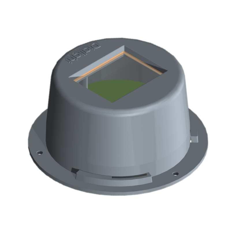

7 Sensor Overview Mounting Enclosure Rim LED Light Sensor Lens Mounting Holes


8 Where to Mount The DLH sensor can be used as a ceiling or wall mount sensor. This will be user defined depending on the layout of the facility and available ambient light sources. Sensor should be mounted away from direct sunlight. 8

9 Mounting Instruction Rev B How to Mount Installation to be performed in accordance with applicable local, regional, and federal regulations. Warning: To avoid the risk of fire, explosion, or electric shock, this product should be installed, inspected, and maintained by a qualified electrician only, in accordance with all applicable electrical codes. To avoid electric shock be certain electrical power is OFF before and during installation and maintenance. Make sure the supply voltage is the same as the rated device voltage. 1. Install the mounting plate to a suitable outlet/junction box using flat head screws. (#8-1/2 or M3.5x12mm screws provided) 2. Connect the power cable conductors as follows: Black wire connects to Line White wire connects to Neutral 3. Feed wires into outlet/junction box through mounting plate and affix device using 3x #8x1/4 long screws. 4. Restore power and verify operation. The sensor will begin to flash green twice indicating it s ready to be added to your gateway. (The green led will flash in a pattern, flash twice, off, flash twice and repeat.) 9

10 Commissioning Rev B It is advised to mount the sensor before discovering it in your network. NOTE: in order for the DLH to function, a schedule needs to be created which turns the DLH feature ON. The DLH will only function when this ON condition is met. Adding Sensor to Gateway: Gateway required during these steps 1. Go to Configure Devices page 2. Turn discovery on and discover DLH device. (Please refer to your gateway owner s manual for further instructions.) NOTE: DLH sensor information displayed Identify: Will display yellow antenna and will flash when identifying Name: This can be a user friendly name and the (64C7) should remain as part of the name Model Name: ZB DLH (short description) Gear: Provides additional information Delete: Deletes the device from being used or needs replacing 10
 e. Ensure Schedule has a DLH ON event e.")
11 Adding a Schedule with a DLH event 1. Configure Schedule a. Go to Configure Schedule s page b. Select Add Schedule Icon i. Name Schedule ii. Give Schedule a description c. Select Configure Icon for schedule i. User can change Name of Schedule ii. User can change Description of Schedule d. Select Days for Schedule to run (Mon-Sun) e. Ensure Schedule has a DLH ON event e. Save Selections a. NOTE: for a more in-depth guide on scheduling, please see Gateway User Manual 11


12 Adding a Group 1. Go to Configure Groups page a. Select Add Group Icon b. Name Group c. Give Group a description d. Save Changes 12


13 2. Go to Configure Groups page and select configure icon for desired group a. User can change Name of Group b. User can change Group Description c. Configure Devices i. Add DLH to Group ii. iii. Add desired lighting devices to group Save Selections 13

14 3. Select Configure icon for DLH on Configure Group page i. TIP: an easy way to commission a DLH profile is to set desired light level at night. With no ambient light influencing readings, this will ensure that your system is always at an acceptable and safe working conditions light level. a. Adjust the Level on Slider bar until the desired light level is reached. i. Note: The slider bar controls the group lights dimmer level. This will allow the user to achieve to the proper dim level the slider may adjust the lights slowly to allow for observation time. b. Select Mode i. Average- This mode will use an average of multiple DLH sensors to reach desired light level ii. Maximum- This mode will use the highest reading from multiple DLH sensors to reach desired light level iii. Minimum- This mode with use the lowest reading from multiple DLH sensors to reach desired light level c. Verify DLH sensor is giving a Measured Illuminance Reading in Lux d. Save Selections 14
15 Assigning Schedule to a Group 1. Go to Configure Groups page 2. Select Configure Icon for desired Group 3. Select Assign Schedules Icon 4. Select Desired Schedule 5. Save selection Your DLH sensor is fully commissioned and is ready to use. For a more in-depth guide on scheduling, grouping and gateway commissioning, please see Gateway User Manual. 15
16 Troubleshooting Sensor is not discovered by the Gateway. Steps to solve: 1. On the Gateway s lighting controller web page turn discovery on. 2. Check the condition of the LED light through the front lens of the sensor. 3. If the green light is flashing twice then the sensor is still trying to join a network, then: a. Verify that it is within 70 ft. of a light that has already joined the network. b. Verify the nearby lights are powered by commanding them to turn on from the web page. c. If the DLH sensor still doesn t discover, replace the sensor. 4. If the green light is not blinking at all then: d. Unplug sensor and plug in again. You should see the green LED double blink at least once. e. Try a node release from the gateway administration page on the gateway. (Contact Dialight sales for the appropriate manual) f. If it does not blink then replace the sensor. g. If it blinks and stops then it has joined a gateway. See if it has joined the gateway you intend. If it has not then check to see if it has joined another gateway in the building. 16
Wireless Occupancy Sensor User Guide
 Wireless Occupancy Sensor Wireless Occupancy Sensor User Guide This Manual covers both the Wide angle and the Narrow long range occupancy sensor. Dialight Part Numbers described here-in are: WOSU22BG2
DESCRIPTION & OPERATION: PIR OCCUPANCY SENSOR MSWSFSP221B-D FEATURES:
 PROJECT NAME: CATALOG NUMBER: NOTES: FIXTURE SCHEDULE: Page: 1 of 5 PIR OCCUPANCY SENSOR DESCRIPTION & OPERATION: These fixture mounted sensors provide multi-level control based on motion and/or daylight
ASSEMBLY AND INSTALLATION INSTRUCTIONS
 T0412 / T0413 ASSEMBLY AND INSTALLATION INSTRUCTIONS WARNING: NOTES: 1. Before installing, consult local electrical codes for wiring and grounding requirements. 2. READ AND SAVE THESE INSTRUCTIONS. Hardware
Radio to radio repeater. airrepeater INSTRUCTIONS MANUAL M A
 Radio to radio repeater airrepeater INSTRUCTIONS MANUAL M98250601-03-16A Pag 2 of 9 Instructions manual Safety Warnings & Symbols DANGER Death, serious injury, or fire hazard could result from improper
Technical Application Guide
 Lighting Control Wireless Occupancy Sensor, Wireless Multi Sensor Technical Application Guide Easily enhance your smart lighting system with the Philips wireless occupancy sensor and multi sensor, which
Radio Control Installation and Operating Instructions System 4
 Radio Control Installation and Operating Instructions System 4 P.O. Box 403, One Cedar Parkway, Jackson, WI 53037 Phone: 800-628-1909 Fax: 262-677-2058 Revision: April 19, 2012 Contents Introduction 3
HIGH/LOW/OFF PIR OUTDOOR PHOTO/MOTION SENSOR IN IP66 ENCLOSURE FOR FLEXIBLE MOUNTING
 HIGH/LOW/OFF PIR OUTDOOR PHOTO/MOTION SENSOR IN IP66 ENCLOSURE FOR FLEXIBLE MOUNTING Product Overview The FSP-2x1B is a family of passive infrared (PIR) outdoor sensors that raise or lower the electric
Installation Instructions
 TECH SUPPORT The Watt Stopper, Inc. 2800 De La Cruz Blvd. Santa Clara, CA 95050, USA Tel: 1(800)879-8585 1(972)578-1699 Fax: 1(972)422-1311 www.wattstopper.com Outdoor 180 & 270 PIR Motion s Model#s: EW-100-120
Satellite LED Plus Pro Instructions
 Satellite LED Plus Pro Instructions To avoid injury and possible electric shock, it is imperative you: READ AND FOLLOW ALL SAFETY INSTRUCTIONS AND WARNINGS Important Warnings Save these Instructions This
ERM-DA. Installation Guide
 ERM-DA Installation Guide ERM-DA Product Overview Echoflex s ERM-DA is an active circuit transmitter that provides a low cost method of using a live electrical circuit as a switch. When the circuit is
SELECTABLE MODE HIGH/LOW/OFF PIR FIXTURE INTEGRATED INDOOR/OUTDOOR MOTION/PHOTO SENSOR
 SELECTABLE MODE HIGH/LOW/OFF PIR FIXTURE INTEGRATED INDOOR/OUTDOOR MOTION/PHOTO SENSOR FSP-22 FSP-212 * Models FSP-22, 12-32VDC Use with dim-to-off driver or ballast or with Wattstopper power pack FSP-212,
FIXTURE INTEGRATED DAYLIGHT DIMMING PHOTOSENSOR
 FIXTURE INTEGRATED DAYLIGHT DIMMING PHOTOSENSOR Product Overview The is a fixture-integrated dimming photosensor. It provides a continuous dimming signal to a 0-10 VDC dimming ballast, based on daylight
Model 5100F. Advanced Test Equipment Rentals ATEC (2832) OWNER S MANUAL RF POWER AMPLIFIER
 OWNER S MANUAL RF POWER AMPLIFIER") Established 1981 Advanced Test Equipment Rentals www.atecorp.com 800-404-ATEC (2832) OWNER S MANUAL Model 5100F RF POWER AMPLIFIER 0.8 2.5 GHz, 25 Watts Ophir RF 5300 Beethoven Street Los Angeles, CA 90066
Established 1981 Advanced Test Equipment Rentals www.atecorp.com 800-404-ATEC (2832) OWNER S MANUAL Model 5100F RF POWER AMPLIFIER 0.8 2.5 GHz, 25 Watts Ophir RF 5300 Beethoven Street Los Angeles, CA 90066
GL BAL GLEDHB 50W COMPACT HIGH BAY B L A Z E L ED H IGH BAY SPECIFICATION SHE ET OPTICAL SPECS ELECTRICAL SPECS DIMENSIONS CERTS OTHER DETAILS
 GL BAL ENERGY & LIGHTING 5W OPTICAL SPECS B L A Z E L ED H IGH BAY SPECIFICATION SHE ET COMPACT HIGH BAY System Efficacy Up to 129 Lm/W (CCT =5K) Lumen Output 6,76 Lumens (CCT = 5K) CCT Beam Angle 9 /
BEAM ANGLES FIXTURE OPTIONS
 GL BAL ENERGY & LIGHTING W OPTICAL SPECS B L A Z E L ED H IGH BAY SPECIFICATION SHE ET Available with ZigBee Wireless Control System Efficacy Up to 126 Lm/W (CCT =5K) Lumen Output 15, Lumens (CCT = 5K)
ASSEMBLY AND INSTALLATION INSTRUCTIONS
 T0436 ASSEMBLY AND INSTALLATION INSTRUCTIONS WARNING: TO AVOID RISK OF ELECTRICAL SHOCK, BE SURE TO SHUT OFF POWER BEFORE INSTALLING OR SERVICING THIS FIXTURE. NOTES: 1. Before installing, consult local
HIGH/LOW/OFF PIR OUTDOOR PHOTO/MOTION SENSOR IN IP66 ENCLOSURE WITH BLUETOOTH
 HIGH/LOW/OFF PIR OUTDOOR PHOTO/MOTION SENSOR IN IP66 ENCLOSURE WITH BLUETOOTH Product Overview The FSP-3x1B is a family of passive infrared (PIR) outdoor sensors that raise or lower the electric lighting
Wireless Z-Wave Control ZRP-100US Z-Wave Repeater USER MANUAL. Introduction
 Wireless Z-Wave Control ZRP-100US Z-Wave Repeater USER MANUAL Introduction Thank you for choosing ZRP-100 Z-Wave Repeater product! ZRP-100 is a Z-Wave repeater with best RF performance to repeat Z-Wave
Installing the FSP-211 Sensor in Light Fixture
 (grey) WATTSTOPPER VOLTAGE HIGH/LOW/OFF PIR FIXTURE INTEGRATED OUTDOOR PHOTO/MOTION SENSOR Product Overview The is a passive infrared (PIR) outdoor sensor that raises or lowers the electric lighting level
Installation Instructions
 SYSTXBBSAM01 EVOLUTION SYSTEM ACCESS MODULE Installation Instructions NOTE: Read the entire instruction manual before starting the installation. pointsett U.S. Pat No. 7,415,102 Fig. 1 - Evolution System
Vigilant LED High Bay Controls - CE. for Indoor and Outdoor Industrial Applications
 Vigilant LED High Bay Controls - CE for Indoor and Outdoor Industrial Applications Vigilant Industrial Applications Controls Take control of your lighting The High Bay lighting control system combines
ELECTRO-MECH SCOREBOARD CO. SL-230 / 330 RF MODEM INSTALLATION MANUAL
 ELECTRO-MECH SCOREBOARD CO. SL-230 / 330 RF MODEM INSTALLATION MANUAL Thank you for choosing an Electro-Mech Scoreboard for your athletic complex. We are confident that this product will give many years
Geotagger N3. User Manual (V1.0) Revised by Geosolve.be (Pol F. Gillard) with personal updates and help. Solmeta Technology Co.
 Revised by Geosolve.be (Pol F. Gillard) with personal updates and help. Solmeta Technology Co.") Geotagger N3 User Manual (V1.0) Revised by Geosolve.be (Pol F. Gillard) with personal updates and help Solmeta Technology Co., Ltd Copyright 2011 Solmeta Technology Co., Ltd. All Rights Reserved 1 Contents
Geotagger N3 User Manual (V1.0) Revised by Geosolve.be (Pol F. Gillard) with personal updates and help Solmeta Technology Co., Ltd Copyright 2011 Solmeta Technology Co., Ltd. All Rights Reserved 1 Contents
APS M1P Single-phase Micro-inverter Installation and User Manual
 APS M1P Single-phase Micro-inverter Installation and User Manual Version: 2.0 ALTENERGY POWER SYSTEM, INC. All rights reserved 1 Contact Information ALTENERGY POWER SYSTEM Inc. 1 Yatai Road, Jiaxing, PR
Indoor Contact Input Photosensor
 General Information Indoor Contact Input Photosensor INSTALLATION SHEET Model# PPS-4 The Indoor Contact Input Photosensor (PPS-4) can be used with any Greengate lighting controller and may also be used
Always there to help you. Register your product and get support at AJ5305D/05. Question? Contact Philips.
 Always there to help you Register your product and get support at www.philips.com/welcome Question? Contact Philips AJ5305D/05 User manual Content 1 Important 2 Safety 2 2 Your Docking Entertainment System
Panoramic Power System. PAN-10, PAN-12 User Guide
 Panoramic Power System Copyright Notice Copyright 2012-2014 Panoramic Power Ltd. All rights reserved. 2 Contents Overview... 4 Workflow... 4 Unpacking the Hardware... 4 Safety Precautions... 5 Hardware
Always there to help you. Register your product and get support at AJ5305D_12. Question? Contact Philips.
 Always there to help you Register your product and get support at www.philips.com/welcome Question? Contact Philips AJ5305D_12 User manual Contents 1 Important 3 Safety 3 2 Your Docking Entertainment System
Experiencing trouble with your zboost setup? Installation Tips. Please note the following important factors in determining zboost performance:
 Experiencing trouble with your zboost setup? Please note the following important factors in determining zboost performance: 1. Vertical Separation: At least 15 vertical feet is needed between the External
Table of Contents. Polytel GMA Glucose Meter Accessory for LifeScan Meters Model PWR USER MANUAL Version: 1
 Table of Contents Polytel GMA Glucose Meter Accessory for LifeScan Meters Model PWR-08-06 USER MANUAL Version: 1 Polymap Wireless 310 S. Williams Blvd. Ste. 350 Tucson, Arizona 85711 (520) 747-1811 Mon-Fri
Light Management Systems for Indoor Use MULTISENSORS
 Light Management Systems for Indoor Use MULTISENSORS MULTISENSORS Daylight and motion sensors both enable greater energy savings to be made and increase the convenience factor. For this reason, we have
2 Pendant Adjustment. Pendant Slider Plate. 3/4 (19mm) IP, (29mm) O.D. Knockouts. 1/2 (13mm) IP, (22mm) O.D. Knockout
 IP, (29mm) O.D. Knockouts. 1/2 (13mm) IP, (22mm) O.D. Knockout") CXB Series LED Luaire Universal Hook and Cord, and Optional Junction box or Pendant Mount with Sensor IMPORTANT SAFEGUARDS When using electrical equipment, basic safety precautions should always be followed
CXB Series LED Luaire Universal Hook and Cord, and Optional Junction box or Pendant Mount with Sensor IMPORTANT SAFEGUARDS When using electrical equipment, basic safety precautions should always be followed
Installation Instructions SKU# , Rated Voltage V~ 50Hz
 Installation Instructions SKU# 240621, 240622 Rated Voltage 220-240V~ 50Hz THANK YOU FOR PURCHASING THIS QUALITY LUCCI PRODUCT, TO ENSURE CORRECT FUNCTION AND SAFETY, PLEASE READ AND SAVE ALL INSTRUCTIONS
PARTS INCLUDED TOOLS & PARTS NEEDED Do not mount on vibrating surfaces. appro to 2.5 meters 12M
 Type: RH60B-LED Ref: 86524 The bulkhead light incorporates a PIR (Passive Infra Red) sensing device which continuously scans a preset operating zone and immediately switches the lamp on when it detects
Agilent G1888 Network Headspace Sampler
 Agilent G1888 Network Headspace Sampler Safety and Regulatory Information Agilent Technologies Notices Agilent Technologies, Inc. 2004 No part of this manual may be reproduced in any form or by any means
TekLink TL100 with Passive Infrared Sensing System Overview
 TekLink TL100 with Passive Infrared Sensing System Overview 1.0 Control Systems CS 1 TekLink TL100 with Infrared Application Guide Contents 1.0 Introduction 2 2.0 Basic Operating Principles 3 3.0 Normal
GE Lighting. High Bay Lighting. (ABV-Series) imagination at work
 imagination at work") GE Lighting Albeo LED Luminaire High Bay Lighting (ABV-Series) imagination at work Product Features Albeo continues to build on the groundbreaking ABH-Series high bay LED luminaire with its latest high
GE Lighting Albeo LED Luminaire High Bay Lighting (ABV-Series) imagination at work Product Features Albeo continues to build on the groundbreaking ABH-Series high bay LED luminaire with its latest high
Applications. HBT02 Transceiver Node. Features. Note: This datasheet is intended for information related to the hardware only.
 Synchrony ighting Control With Wireless Technology HBT01 / HBT02 with HC038V / HCD038 Built-in Detachable Version Applications The freedom of wireless mesh networks configured by smartphone APP s considerably
High Bay Occupancy Sensor for Use with Electronic Ballast HID Luminaires
 Instruction Bulletin 63249-500-08A6 05/2011 High Bay Occupancy Sensor for Use with Electronic Ballast HID Luminaires SLSPIP210EB and SLSPIP210EBCT INTRODUCTION Figure 1: High Bay Occupancy Sensor for Use
Tube Facing Tool.
 www.swagelok.com Tube Facing Tool This manual contains important information for the safe and effective operation of the Swagelok TF72 series tube facing tool. Users should read and understand its contents
EBDSM-PRM Product Guide
 EBDSM-PRM Product Guide Ceiling PIR presence/absence detector Overview The EBDSM-PRM PIR (passive infrared) presence detector provides automatic control of lighting loads with optional manual control.
APS M1P Single-phase Micro-inverter Installation and User Manual
 APS M1P Single-phase Micro-inverter Installation and User Manual Version: 1.0 ALTENERGY POWER SYSTEM, INC. All rights reserved 1 Contact Information ALTENERGY POWER SYSTEM Inc. 1 Yatai Road, Jiaxing, PR
LOAD AWG Solid CU Wire Only LINE NEUT FSP-211. High/Low PIR Occupancy Sensor 230 VAC, 50 Hz 1200W max ballast 5E4
 DESCRIPTION AND OPERATION The is a motion sensor that dims lighting from high to low based on movement. This slim, low-profile sensor is designed for installation inside the bottom of a light fixture body.
Grid Radar Installation Manual
 Grid Radar Installation Manual MODELS GN-RD-001 120V Single Phase / Wye, 240V Single Phase, with Neutral GN-RD-002 277V 3-Phase Wye, with Neutral GN-RD-003 480V 3-Phase Delta, no Neutral GN-RD-004 208V
Active UTP Transceiver Hub Installation Guide
 Active UTP Transceiver Hub Installation Guide Models Include: HubWayLDH8 HubWayLDH16 - UL Listed eight (8) Channels - UL Listed sixteen (16) Channels Rev. 032108 More than just power. TM Overview: Altronix
Table of Contents. Polytel GMA Glucose Meter Accessory Model PWR USER MANUAL Version: 2
 Table of Contents Polytel GMA Glucose Meter Accessory Model PWR-08-03 USER MANUAL Version: 2 Polymap Wireless 310 S. Williams Blvd. Ste. 346 Tucson, Arizona 85711 (520) 747-1811 www.polymapwireless.com
INSTALLATION WARNING: BEFORE COMMENCING INSTALLATION ISOLATE YOUR MAINS ELECTRIC SUPPLY
 TT403- K (1000W) Wireless Inline Switch Product Description The TT403- K is a 1000W switchable wireless receiver and can be used to control a lighting system, extractor fan or other appliance. It does
Installation/User Manual
 Installation/User Manual APS YC500-A Photovoltaic Grid-connected Inverter Version 4.1 1/15 APS America 1015 Hostmark St. Ste 104; Poulsbo, WA 98370 TEL: 206-855-5100 EMAIL: info@apsamerica.com WEB: www.apsamerica.com
Table of Contents. Polytel GMA Glucose Meter Accessory for Bayer Ascensia Contour Model PWR USER MANUAL Version: B
 Table of Contents Polytel GMA Glucose Meter Accessory for Bayer Ascensia Contour Model PWR-08-07 USER MANUAL Version: B Polymap Wireless 310 S. Williams Blvd. Ste. 350 Tucson, Arizona 85711 (520) 747-1811
SVS SoundPath Wireless Audio Adapter Owner s Manual
 SVS SoundPath Wireless Audio Adapter Owner s Manual SVS SoundPath Wireless Audio Adapter Thank you for choosing SVS! The SoundPath Wireless Audio Adapter reduces subwoofer cable clutter without sacrificing
Table of Contents. Polytel GMA Glucose Meter Accessory for Abbott FreeStyle Lite and FreeStyle Freedom Lite Model PWR USER MANUAL Version: B
 Table of Contents Polytel GMA Glucose Meter Accessory for Abbott FreeStyle Lite and FreeStyle Freedom Lite Model PWR-08-09 USER MANUAL Version: B Polymap Wireless 310 S. Williams Blvd. Ste. 350 Tucson,
High/Low Bay Passive Infrared Occupancy Sensor
 Models Sensors: HBP-111-L7, with IR remote capability HBP-112-L7, no IR capability High/Low Bay Passive Infrared Occupancy Sensor Mounting Modules: HBP-EM1 extender module HBP-SM1 surface mount module
Sensors. EasySense. Fixture-Mount for Basic Grouping
 Sensors EasySense Fixture-Mount for Basic Grouping The Philips EasySense fixture-mount sensor is the ideal solution for per-fixture control of new light fixtures. It combines occupancy sensing, daylight
INSTALLATION INSTRUCTIONS INSTALLATION INSTRUCTIONS
 FOR RECESSED EDGE-LIT LED EXIT SIGN Standard and New York Approved Models (Emergency, non-emergency and X2 Dual Circuit operation) READ AND FOLLOW ALL SAFETY INSTRUCTIONS IMPORTANT SAFEGUARDS: When using
SECTION GPS WIRELESS CLOCK SYSTEMS
 PART 1 GENERAL 1.1 SECTION INCLUDES A. G.P.S. Receiver B. Primary Transmitter C. Satellite Transmitter D. Analog Clocks E. Digital Clocks 1.2 REGULATORY REQUIREMENTS SECTION 27 53 13 GPS WIRELESS CLOCK
INSTALLATION AND MAINTENANCE MANUAL FOR P/N: D564-A /240VAC, 50/60 Hz, L864 RED MEDIUM INTENSITY BEACON
 INSTALLATION AND MAINTENANCE MANUAL FOR P/N: D564-A13-001 120/240VAC, 50/60 Hz, L864 RED MEDIUM INTENSITY BEACON 1 of 14 Contents Page List of Figures and Tables...2 Reference Drawings...2 Section 1: Overview...3
INTELLIMETER REGISTER
 INTELLIMETER REGISTER MODEL RG2 INSTALLATION AND CONNECTIONS INSTALLATION MANUAL WARNING: Any work on or near energized metering equipment can present a danger of electrical shock. All work on these products
Sensors. EasySense. Fixture-Mount for Basic Grouping
 Sensors EasySense Fixture-Mount for Basic Grouping The Philips EasySense fixture-mount sensor is the ideal solution for per-fixture control of new light fixtures. It combines occupancy sensing, daylight
Operation Manual. Congratulations on purchasing your high quality AIMS Power pure sine inverter!
 Operation Manual Congratulations on purchasing your high quality AIMS Power pure sine inverter! It is very important that you read and understand this instruction manual completely prior to use. Contained
Wireless Ceiling Mount Sensor
 Wireless Ceiling Mount Sensor Lutron s occupancy and vacancy sensors are wireless ceiling-mounted battery-powered passive infrared (PIR) sensors that automatically control lights via RF communication to
2.4G. wireless transmission technology. Technical Application Guide for UP-SHINE LED Ceiling light UP-AL W-AW
 2.4G wireless transmission technology Technical Application Guide for UP-SHINE LED Ceiling light UP-AL2-14-25W-AW Introduction 2.4G wireless transmission technology AL2 Oyster LED ceiling light can be
THIS SHEET CONTAINS IMPORTANT SAFETY INSTRUCTIONS. SAVE THESE INSTRUCTIONS.
 LumeLEX 2026 SERIES INSTALLATION INSTRUCTIONS Important THIS SHEET CONTAINS IMPORTANT SAFETY INSTRUCTIONS. SAVE THESE INSTRUCTIONS. Warning This product must be installed in accordance with National Electrical
Nemalux INSTALLATION INSTRUCTIONS APPLICATION 1-4
 I N D U S T R I A L rev. A- INSTALLATION INSTRUCTIONS *PENDING* E77827 E77827 APPLICATION MR3 & MR6 Luminaires are suitable for use in the following areas as defined by the National Electrical Code (NEC)
Digital Electronic Thermostat With RF
 RT300RF Manual Altech 005_89 06/05/2014 08:56 Page 1 Digital Electronic Thermostat With RF Instruction Manual Model No ALTHC015 RT300RF Manual Altech 005_89 06/05/2014 08:56 Page 2 2 ALTHC015 INSTRUCTION
KeyPre KP6 - Electronic Instrument Preamplifier
 ! USE ONLY WITH 250V FUSE KeyPre KP6 - Electronic Instrument Preamplifier USER S GUIDE 0 10dB 0 10dB 0 10dB 0 10dB 0dB 10dB 0 10dB AVEDIS AUDIO E L E C T R O N I C S AC INPUT 100-240VAC 50/60 Hz 1.1" 1.225"
Sensors. EasySense. Fixture-Mount Advanced Grouping for Evokit
 Sensors EasySense Fixture-Mount Advanced Grouping for Evokit The Philips EasySense fixture-mount sensor is the ideal solution for per-fixture control of new light fixtures. It combines occupancy sensing,
INSTALLATION AND MAINTENANCE MANUAL FOR P/N: D564-XXX-001 L864 RED MEDIUM INTENSITY BEACON
 INSTALLATION AND MAINTENANCE MANUAL FOR P/N: D564-XXX-001 L864 RED MEDIUM INTENSITY BEACON Page 1 of 8 Contents Page List of Figures and Tables... 2 Reference Drawings... 2 Section 1: Overview... 3 Section
Electro-Mech Scoreboard Co. Product Guide
 Electro-Mech Scoreboard Co. Product Guide 72 Industrial Boulevard Wrightsville, GA 31096 Phone: (800) 445-7846 Fax: (478) 864-0212 www.electro-mech.com Table of Contents Introduction to the ScoreLink System...3
SI-125 Power Amplifier Manual 6205 Kestrel Road; Mississauga, Ontario; Canada; L5T 2A1 November 2016, Rev 0.5
 SI-125 Power Amplifier Manual 6205 Kestrel Road; Mississauga, Ontario; Canada; L5T 2A1 November 2016, Rev 0.5 Phone: (905) 564-0801 Fax: (905) 564-0806 www.telecor.com E:\T2-108\T2-M108-ABC\T2-M108-B.doc/AD
RF Wireless Version On/off Control
 RF Wireless Version On/off Control HC08V/RF + HC0RF Loop in 8 hours Detection Pattern 0 /88 / 5 /95 MHz Ambient daylight threshold Loop out manual on Condominium control 5s~0min ~50Lux Rotary coding switch(tx)
Explosion Proof Page/Talk Paging Amplifier
 Industrial Communications Worldwide Explosion Proof Page/Talk Paging Amplifier Installation & Operation 7552-10 th Street. N.E. Calgary Alberta, Canada T2E W1 Ph: 403.25.3100 \ email:info@guardiantelecom.com
Limelight by Lutron Wireless Lighting Control System
 Limelight by Lutron Wireless Lighting Control System 3691100d 1 10.16.18 Limelight by Lutron is a wireless lighting control system for exterior parking garage and parking lot applications. Limelight by
CAUTION. RXM5010 Touchscreen Remote Installation and Operation Manual MODEL: RXM5010
 RXM5010 Touchscreen Remote Installation and Operation Manual MODEL: RXM5010 / Touchscreen Remote with 110v receiver and battery for R-Series and RP-Series Fireplaces C US This kit should be installed by
LED PowerBlinder 4 ORDERCODE 41320
 LED PowerBlinder 4 ORDERCODE 41320 Congratulations! You have bought a great, innovative product from Showtec. The Showtec LED PowerBlinder brings excitement to any venue. Whether you want simple plug-&-play
DuroSite Series LED High Bay for Indoor and Outdoor Industrial Applications. Patent Pending
 Patent Pending DuroSite Series LED High Bay for Indoor and Outdoor Industrial Applications DuroSite Series LED High Bay Features & Benefits L70 rated for >100,000 hours @ 45 C ambient 5 year full performance
English RACON SERIES II RADIO CONTROL SERVICE MANUAL
 English 22.2.2007 RACON SERIES II RADIO CONTROL SERVICE MANUAL Read the instructions supplied with the product before installation and commissioning. Keep the instructions in a safe place for future reference.
& Operation Manual. Installation. Installation Manual Of SP-CT GR - UM A - 01
 Installation Manual Of SP-CT Shenzhen Growatt New Energy Technology CO.,LTD Building B, Jiayu Industrial Zone,Guanghui Road #28, Longteng Community, Shiyan, Baoan District, Shenzhen, P.R. China Installation
I n s ta l l at i o n M a n u a l f o r T E D P r o H o m e T E D P r o L i t e A B C Rev 4.0
 I n s t a l l a t i o n M a n u a l f o r T E D P r o H o m e T E D P r o L i t e A B C Rev 4.0 IMPORTANT: The installation of your TED Pro Home system is a several-step process. The 1st step is the installation
CDG. Carbon Dioxide - User Manual Gas Detector. 1 Intended Use. 2 Functional Description. 3 Installation. 4 Electrical Connection.
 Carbon Dioxide - User Manual 1 Intended Use 2 Functional Description 2.1 Control Mode 2.2 Sensor 3 Installation 3.1 Mounting instructions 3.2 Installation 4 Electrical Connection 4.1 Instruction 5 Commissioning
Driveway Alarm INSTALLATION MANUAL
 WIRELESS ACCESS CONTROLS Driveway Alarm INSTALLATION MANUAL Mounting post Transmitter Receiver Transformer Sensor Kit Includes: Transmitter Module Sensor Receiver Transformer Mounting post (3 pieces) Installation
CP /240-MC4 User Manual
 CP-250-60-208/240-MC4 User Manual Chilicon Power LLC Jan 2014 1 CONTENTS Important Safety Instructions... 3 Safety Instructions... 3 CP-250 Microinverter System Introduction... 4 Inverter Label Information...
EBDSPIR-AT-DD. RF ceiling PIR presence detector DALI / DSI dimming. Product Guide. Overview. Features
 Product Guide EBDSPIR-AT-DD RF ceiling PIR presence detector DALI / DSI dimming Overview The EBDSPIR-AT-DD is a passive infrared (PIR) motion sensor combined with two output channels capable of controlling
Your Rocktron Bass15 Bass Amplifier has been tested and complies with the following Standards and Directives as set forth by the European Union:
 Instruction Manual Your Rocktron Bass15 Bass Amplifier has been tested and complies with the following Standards and Directives as set forth by the European Union: Standard(s): IEC60065 Professional Audio/Video
ASSEMBLY AND INSTALLATION INSTRUCTIONS
 T0103 ASSEMBLY AND INSTALLATION INSTRUCTIONS WARNING: TO AVOID RISK OF ELECTRICAL SHOCK, BE SURE TO SHUT OFF POWER WHILE INSTALLING OR SERVICING THIS FIXTURE. NOTES: 1. Before installing, consult local
Sensors. EasySense. Fixture-Mount for Advanced Grouping
 Sensors EasySense Fixture-Mount for Advanced Grouping The Philips EasySense fixture-mount sensor is the ideal solution for per-fixture control of new light fixtures. It combines occupancy sensing, daylight
User Manual March 2008
 User Manual March 008 Motor Silent Gliss 900, 90, 90, 903 Motor Silent Gliss 9030, 903, 903, 9033 Usermanual Motors 90x_903x Page Copyright April 007 by Silent Gliss International Ltd., 3073 Gümligen/Berne
INSTALLATION MANUAL GIOTTO SCREEN
 INSTALLATION MANUAL GIOTTO SCREEN Before installing the Giotto screen, please read the following instructions carefully: The Giotto screen must be used INDOORS ONLY. It is forbidden to stay under the Giotto
Sensors. EasySense. Fixture-Mount for Advanced Grouping
 Sensors EasySense Fixture-Mount for Advanced Grouping The Philips EasySense fixture-mount sensor is the ideal solution for per-fixture control of new light fixtures. It combines occupancy sensing, daylight
Dawson DSM150. Digital Light Meter User s Manual
 Dawson DSM150 Digital Light Meter User s Manual TABLE OF CONTENTS LIMITED WARRANTY AND LIMITATION OF LIABILITY... 3 Out of Box... Error! Bookmark not defined. Accessories... 4 Safety Information... 6 Certification...
CXB Series SAVE THESE INSTRUCTIONS FOR FUTURE REFERENCE. LED Luminaire TO INSTALL: INSTALLATION INSTRUCTIONS INSTRUCTIONS D INSTALLATION
 CXB Series LED Luaire Junction Box, Pendant and Hook and Cord IMPORTANT SAFEGUARDS When using electrical equipment, basic safety precautions should always be followed including the following: READ AND
IRIS \ IRIS-I QUICK SET-UP GUIDE STEP 1 INSTALL
 IRIS \ IRIS-I QUICK SET-UP GUIDE STEP 1 INSTALL Confirm contents of package: 1 sensor, 1 cable, 1 wide lens (default), 1 narrow lens, mounting template, User s Guide. Install the sensor at the desired
PPS MFS series - Installation Guide. Power Protector Stabilizer V 3.8 1
 Power Protector Stabilizer MFS Series - Installation Guide - V 3.8 1 1. Safety instructions The following document applies to PPS MFS-i / -ir / -if and PPS MFS-L / -LR What this chapter contains This chapter
UNIT A 8-30VDC 8-28VAC POWER V IN3 IN4 COM1/2 NO3 NO4 IN1 IN2 GND NO1 NO2 COM3/4 ANY 8-28VAC OR 8-30VDC POWER ADAPTER (SOLD SEPARATELY)
") (sold pre-paired) Installation Guide Industrial Wireless ZigBee Relay ILLUMRA Relay Receivers should NOT be installed in a location where the unit will be in close proximity to the light bulb(s) or other
(sold pre-paired) Installation Guide Industrial Wireless ZigBee Relay ILLUMRA Relay Receivers should NOT be installed in a location where the unit will be in close proximity to the light bulb(s) or other
Important Safety Information
 OWNER'S MANUAL Important Safety Information 1. Read these instructions. 2. Keep these instructions. 3. Heed all warnings. 4. Follow all instructions. 5. Do not use this apparatus near water. 6. Clean only
STAS multirail accessories
 STAS multirail accessories STAS multirail accessories Assemble your STAS multirail system step by step. In this brochure we have created an overview of all rail types, light fixtures, spotlights, adapters,
Setup Guide. support.spruceirrigation.com.
 FCC Compliance Statement This device complies with Part 15 of the FCC Rules. Operation is subject to the following two conditions: (1) this device may not cause harmful interference, and (2) this device
PORTABLE HALOGEN WORK LIGHT OWNER S MANUAL
 PORTABLE HALOGEN WORK LIGHT OWNER S MANUAL L-9001 (29278) L-9002 (29276) WARNING: Read carefully and understand all ASSEMBLY AND OPERATION INSTRUCTIONS before operating. Failure to follow the safety rules
Operating instructions Diffuse reflection sensor with background suppression O1D101 O1D / / 2018
 Operating instructions Diffuse reflection sensor with background suppression O1D101 O1D104 706114 / 00 02 / 2018 Contents 1 Preliminary note...3 1.1 Symbols used...3 1.2 Warning signs used...3 2 Safety
General Installation Instructions LED
 General Installation Instructions LED To reduce the risk of death, personal injury or property damage from fire, electric shock, falling parts, cuts/abrasions and other hazards, please read all warnings
F10I-EGSM Single System
 F10I-EGSM Single System 1 Table of contents How it works... 3 Package contents... 4 Troubleshooting... 14 Specifications... 15 Product Warranty... 16 Safety Warnings... 17 2 How it works Huaptec F10I-EGSM